AIR CONDITIONING
3.6L VIN 7
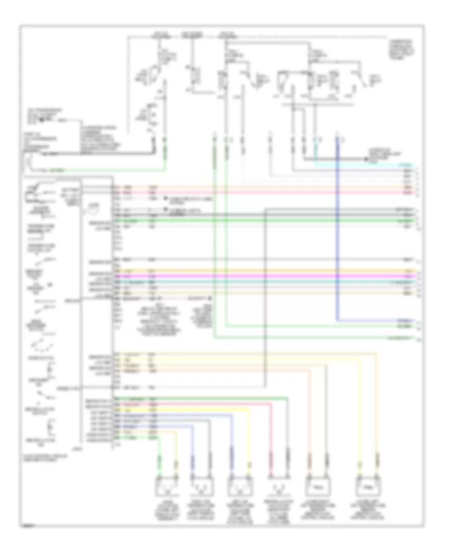
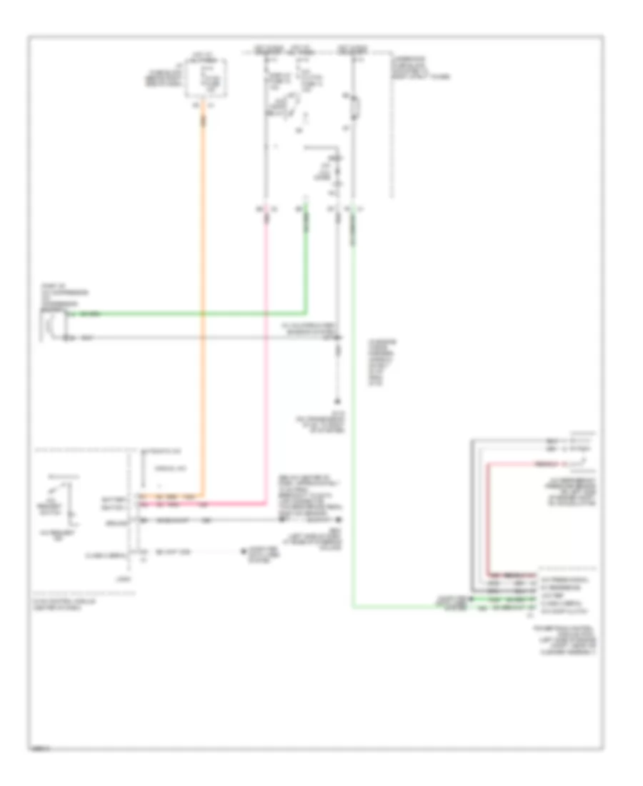
3.6L VIN 7, Automatic A/C Wiring Diagram (1 of 2) for Buick Allure CXS 2007
 https://portal-diagnostov.com/license.html
Automotive Electricians Portal FZCO
Automotive Electricians Portal FZCO
https://portal-diagnostov.com/license.html
https://portal-diagnostov.com/license.html
Automotive Electricians Portal FZCO
Automotive Electricians Portal FZCO
List of elements for 3.6L VIN 7, Automatic A/C Wiring Diagram (1 of 2) for Buick Allure CXS 2007:
- (in back of right headlamp on frame) g100
- (in engine wiring harness, approximately 20 cm from g115) (w/ california pzev emission system) s114
- (mounted to bank 1 cylinder head above exhaust manifold) g115
- (part of a/c compressor) a/c compressor clutch
- A/c clu diode
- A/c clutch fuse 13 10a
- A/c comp relay
- A/c compressor clutch solenoid
- A/c compressor temperature switch
- A/c request ind
- A/c request switch
- A10
- A11
- A12
- A18
- A19
- Air temp a
- Air temp b
- Auto
- B10
- B11
- B12
- Battery
- Blower motor sw
- C18
- C19
- Class 2 serial
- Computer data lines system interior lights system
- Defogger
- E10
- Fan 1 fuse 29 30a
- Fan 1 relay
- Fan 2 fuse 32 30a
- Fan 2 relay
- Fan 3 relay
- G202 (left side of dash, at base of steering column)
- Ground
- High
- Hot at all times
- Hot in run or start
- Hvac control module (center of dash)
- Ign 1 volt
- Illum
- Ind
- K14
- K15
- K18
- K19
- L14
- Left air temperature actuator (left side of dash, on hvac module)
- Logic
- Low
- Low ref
- Lower left air temperature sensor (behind hvac control module)
- Lower right air temperature sensor (behind hvac control module)
- M14
- M15
- M18
- M19
- Mode actuator (lower left side of hvac assembly)
- Mode door a
- Mode door b
- Mode switch
- Nca
- Off
- Pnk
- Rear defogger switch
- Reciration a
- Reciration b
- Recirculation
- Recirculation actuator (near right "a" pillar, on upper hvac case)
- Recirculation switch
- Right air temperature actuator (right side of hvac module)
- S211 (below center of dash, approximately 10 cm from breakout to data link connector towards brake pedal position sensor)
- Sensor sig
- Speed ctrl
- Tan
- Temperature control sw
- Underhood fuse block (mounted to right strut tower)
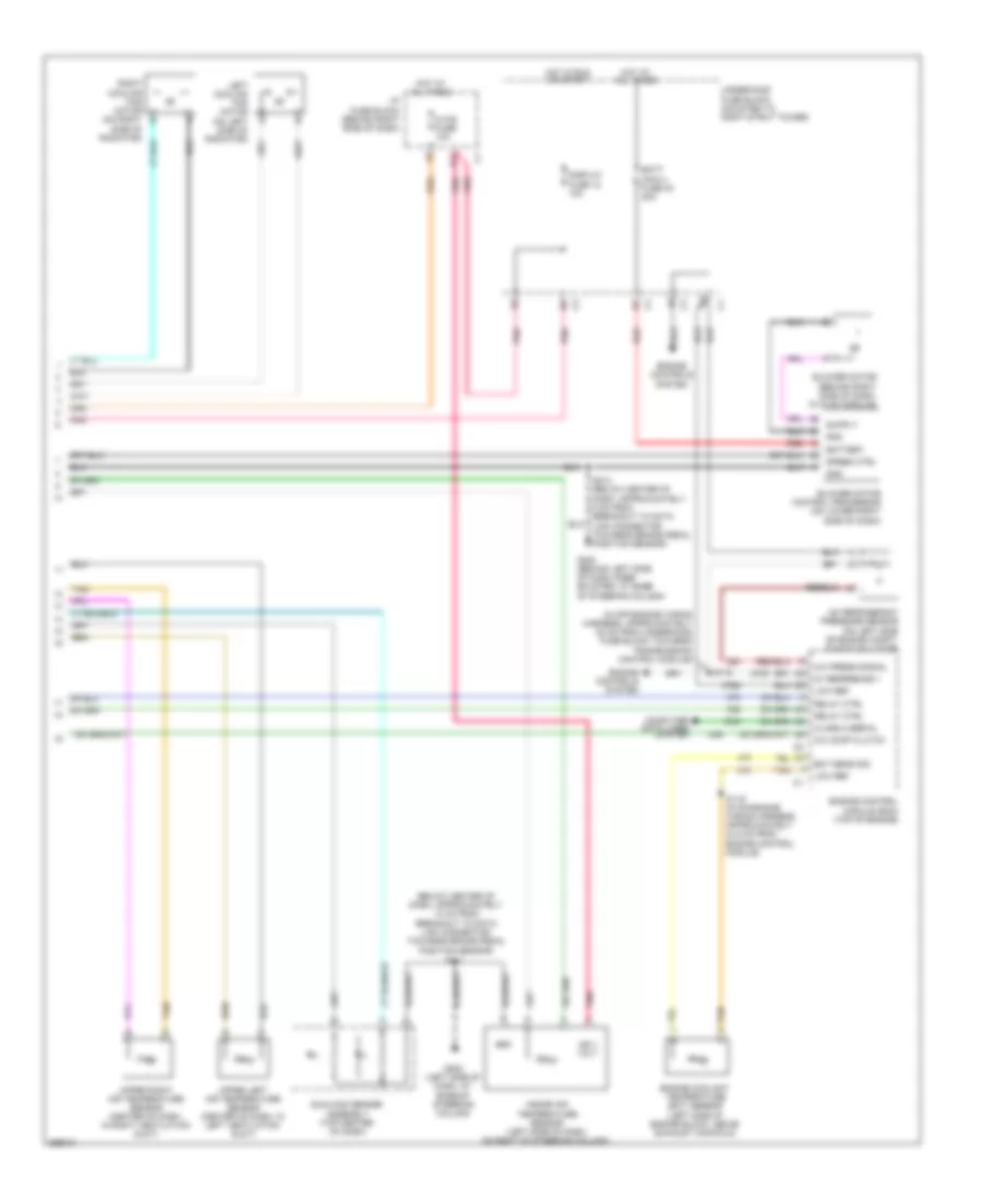
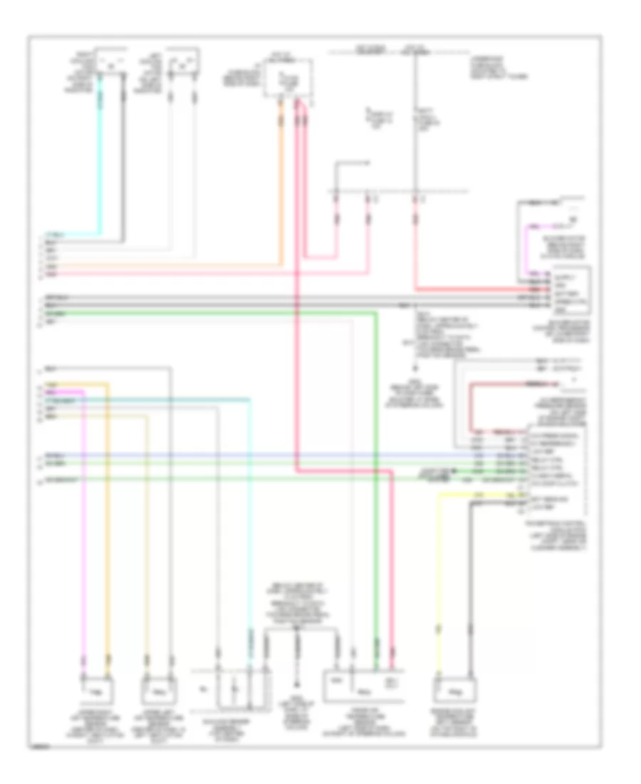
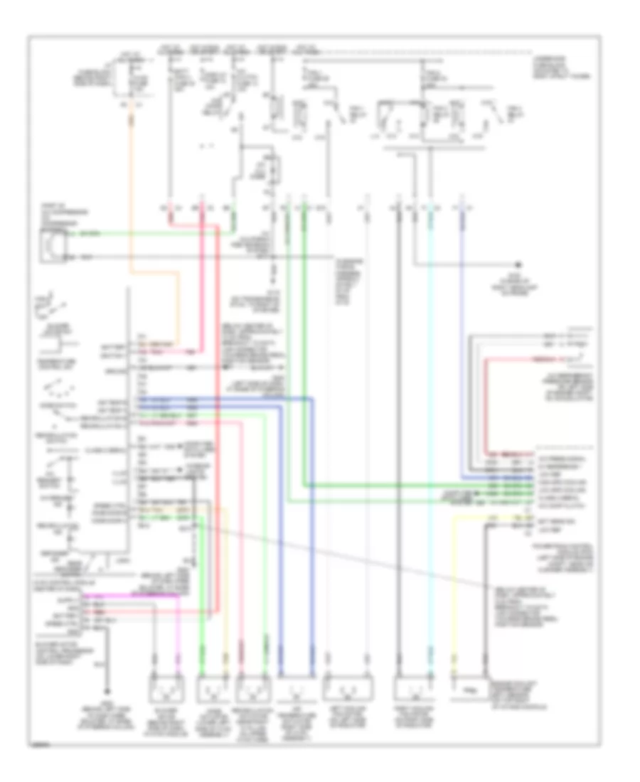
3.6L VIN 7, Automatic A/C Wiring Diagram (2 of 2) for Buick Allure CXS 2007
List of elements for 3.6L VIN 7, Automatic A/C Wiring Diagram (2 of 2) for Buick Allure CXS 2007:
- (below center of dash, approximately 10 cm from breakout to data link connector towards brake pedal position sensor)
- (in off-engine wiring harness, approximately 32 cm from underhood fuse block towards transmission control module)
- 5v reference 1
- A/c comp clutch
- A/c press signal
- A/c refrigerant pressure sensor (on left side of engine compt, on accumulator)
- Batt main 4 fuse 30 30a
- Battery
- Blower motor (behind right side of dash, in hvac module)
- Blower motor control processor (on lower right side of dash)
- Class 2 serial
- Computer data lines system
- D11
- Display fuse 18 10a
- Ect sens sig
- Engine control module (ecm) (top of engine)
- Engine controls system
- Engine coolant temperature (ect) sensor (left side of engine block, above exhaust manifold)
- G200 (behind left side of dash knee bolster, at base of steering column)
- G202 (left side of dash, at base of steering column)
- Gnd
- Hot at all times
- Hot in run or start
- Hvac fuse 10a
- I/p fuse block (behind right side of dash)
- Ign 1 volt
- Inside air temperature sensor (left side of dash, on right of steering column)
- Left cooling fan motor (on left side of radiator)
- Low ref
- Pnk
- Red
- Relay ctrl
- Right cooling fan motor (on right b
- S118
- S119 (in on-engine wiring harness, approximately 34.5 cm from engine control module)
- S211
- S213 (below center of dash, approximately 5 cm from breakout to data link connector towards brake pedal position sensor)
- Speed ctrl
- Sunload sensor assembly (top center of dash)
- Tan
- Underhood fuse block (mounted to right strut tower)
- Upper left air temperature sensor (center of dash, in left ventilation duct)
- Upper right air temperature sensor (center of dash, in right ventilation duct)
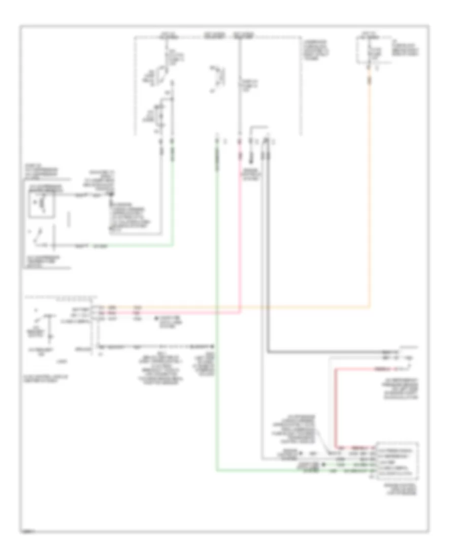
3.6L VIN 7, Compressor Wiring Diagram for Buick Allure CXS 2007
List of elements for 3.6L VIN 7, Compressor Wiring Diagram for Buick Allure CXS 2007:
- (in engine wiring harness, approximately 20 cm from g115) (w/ california pzev emission system) s114
- (in off-engine wiring harness, approximately 32 cm from underhood fuse block towards transmission control module)
- (mounted to bank 1 cylinder head above exhaust manifold) g115
- (part of a/c compressor) a/c compressor clutch
- 5v reference 1
- A/c clu diode
- A/c clutch fuse 13 10a
- A/c comp clutch
- A/c comp relay
- A/c compressor clutch solenoid
- A/c compressor temperature switch
- A/c press signal
- A/c refrigerant pressure sensor (on left side of engine compt, on accumulator)
- A/c request ind
- A/c request switch
- Battery
- Class 2 serial
- Computer data lines system
- Display fuse 18 10a
- Engine control module (ecm) (top of engine)
- Engine controls system
- G202 (left side of dash, at base of steering column)
- Ground
- Hot at all times
- Hot in run or start
- Hvac control module (center of dash)
- Hvac fuse 10a
- I/p fuse block (behind right side of dash)
- Ign 1 volt
- Logic
- Low ref
- Nca
- Pnk
- S118
- S211 (below center of dash, approximately 10 cm from breakout to data link connector towards brake pedal position sensor)
- Underhood fuse block (mounted to right strut tower)
3.8L VIN 2
3.8L VIN 2, Automatic A/C Wiring Diagram (1 of 2) for Buick Allure CXS 2007
List of elements for 3.8L VIN 2, Automatic A/C Wiring Diagram (1 of 2) for Buick Allure CXS 2007:
- (in back of right headlamp on frame) g100
- (in engine wiring harness, approximately 20 cm from g115) (w/ california pzev emission system) s114
- (on transmission stud, to right of starter) g115
- (part of a/c compressor) a/c compressor clutch
- A/c clu diode
- A/c clutch fuse 13 10a
- A/c comp relay
- A/c request ind
- A10
- A11
- A12
- A18
- A19
- Air temp a
- Air temp b
- Auto
- B10
- B11
- B12
- Battery
- Blower motor sw
- C18
- C19
- Class 2 serial
- Computer data lines system
- Defogger
- E10
- Fan 1 fuse 29 30a
- Fan 1 relay
- Fan 2 fuse 32 30a
- Fan 2 relay
- Fan 3 relay
- G202 (left side of dash, at base of steering column)
- Ground
- High
- Hot at all times
- Hot in run or start
- Hvac control module (center of dash)
- Ign 1 volt
- Illum
- Ind
- Interior lights system
- K14
- K15
- K18
- K19
- L14
- Left air temperature actuator (left side of dash, on hvac module)
- Logic
- Low
- Low ref
- Lower left air temperature sensor (behind hvac control module)
- Lower right air temperature sensor (behind hvac control module)
- M14
- M15
- M18
- M19
- Mode actuator (lower left side of hvac assembly)
- Mode door a
- Mode door b
- Mode switch
- Off
- Pnk
- Rear defogger switch
- Reciration a
- Reciration b
- Recirculation
- Recirculation actuator (near right "a" pillar, on upper hvac case)
- Recirculation switch
- Request switch a/c
- Right air temperature actuator (right side of hvac module)
- S211 (below center of dash, approximately 10 cm from breakout to data link connector towards brake pedal position sensor)
- Sensor sig
- Speed ctrl
- Tan
- Temperature control sw
- Underhood fuse block (mounted to right strut tower)
3.8L VIN 2, Automatic A/C Wiring Diagram (2 of 2) for Buick Allure CXS 2007
List of elements for 3.8L VIN 2, Automatic A/C Wiring Diagram (2 of 2) for Buick Allure CXS 2007:
- (below center of dash, approximately 10 cm from breakout to data link connector towards brake pedal position sensor) s211
- 5v reference 2
- A/c comp clutch
- A/c press signal
- A/c refrigerant pressure sensor (on left side of engine compt, on accumulator)
- Batt main 4 fuse 30 30a
- Battery
- Blower motor (behind right side of dash, in hvac module)
- Blower motor control processor (on lower right side of dash)
- Class 2 serial
- Computer data lines system
- D11
- Display fuse 18 10a
- Ect sens sig
- Engine coolant temperature (ect) sensor (on top right of intake manifold)
- G200 (behind left side of dash knee bolster, at base of steering column)
- G202 (left side of dash, at base of steering column)
- Gnd
- Hot at all times
- Hot in run or start
- Hvac fuse 10a
- I/p fuse block (behind right side of dash)
- Ign 1 volt
- Inside air temperature sensor (left side of dash, on right of steering column)
- Left cooling fan motor (on left side of radiator)
- Low ref
- Pnk
- Powertrain control module (pcm) (left side of engine compt, near air cleaner assembly)
- Red
- Relay ctrl
- Right cooling fan motor (on right b
- S213 (below center of dash, approximately 5 cm from breakout to data link connector towards brake pedal position sensor)
- Speed ctrl
- Sunload sensor assembly (top center of dash)
- Tan
- Underhood fuse block (mounted to right strut tower)
- Upper left air temperature sensor (center of dash, in left ventilation duct)
- Upper right air temperature sensor (center of dash, in right ventilation duct)
3.8L VIN 2, Compressor Wiring Diagram for Buick Allure CXS 2007
List of elements for 3.8L VIN 2, Compressor Wiring Diagram for Buick Allure CXS 2007:
- (below center of dash, approximately 10 cm from breakout to data link connector towards brake pedal position sensor) s211
- (in engine wiring harness, approxi- mately 20 cm from g115)
- (left side of engine compt, near air cleaner assembly)
- (part of a/c compressor) a/c compressor clutch
- (w/ california pzev emission system) s114
- 5v reference
- A/c clu diode
- A/c clutch fuse 13 10a
- A/c comp clutch
- A/c comp relay
- A/c press signal
- A/c refrigerant pressure sensor (on left side of engine compt, on accumulator)
- A/c request ind
- A/c request switch
- Automatic a/c
- Battery
- Class 2 serial
- Computer data lines system
- Display fuse 18 10a
- G115 (on transmission stud, to right of starter)
- G202 (left side of dash, at base of steering column)
- Ground
- Hot at all times
- Hot in run or start
- Hvac control module (center of dash)
- Hvac fuse 10a
- I/p fuse block (behind right side of dash)
- Ignition 1
- Logic
- Low ref
- Manual a/c
- Pnk
- Powertrain control module (pcm)
- Underhood fuse block (mounted to right strut tower)
3.8L VIN 2, Manual A/C Wiring Diagram for Buick Allure CXS 2007
List of elements for 3.8L VIN 2, Manual A/C Wiring Diagram for Buick Allure CXS 2007:
- (below center of dash, approximately 10 cm from breakout to data link connector towards brake pedal position sensor) s211
- (below center of dash, approximately 5 cm from breakout to data link connector towards brake pedal position sensor)
- (in engine wiring harness, approxi- mately 20 cm from g115)
- (part of a/c compressor) a/c compressor clutch
- (w/ california pzev emission system) s114
- 5v reference 1
- A/c clu diode
- A/c clutch fuse 13 10a
- A/c comp clutch
- A/c comp relay
- A/c press signal
- A/c refrigerant pressure sensor (on left side of engine compt, on accumulator)
- A/c request ind
- A/c request switch
- A10
- A11
- A12
- A18
- A19
- Air temp a
- Air temp b
- Air temperature actuator (right side of hvac assembly)
- B10
- B11
- B12
- Batt main 4 fuse 30 30a
- Battery
- Blower motor (behind right side of dash, in hvac module)
- Blower motor control processor (on lower right side of dash)
- Blower motor sw
- C18
- C19
- Class 2 serial
- Computer data lines system
- Defogger
- Display fuse 18 10a
- E10
- Ect sens sig
- Engine coolant temperature (ect) sensor (on top right of intake manifold)
- Fan 1 fuse 29 30a
- Fan 1 relay
- Fan 2 fuse 32 30a
- Fan 2 relay
- Fan 3 relay
- G100 (in back of right headlamp on frame)
- G115 (on transmission stud, to right of starter)
- G200 (behind left side of dash knee bolster, at base of steering column)
- G202 (left side of dash, at base of steering column)
- Gnd
- Ground
- High
- High spd cooling
- Hot at all times
- Hot in run or start
- Hvac control module (center of dash)
- Hvac fuse 10a
- I/p fuse block (behind right side of dash)
- Ignition 1
- Illum
- Ind
- Interior lights system
- K14
- K15
- K18
- K19
- L14
- Left cooling fan motor (on left side of radiator)
- Logic
- Low
- Low ref
- Low spd cooling
- M14
- M15
- M18
- M19
- Mode actuator (lower left side of hvac assembly)
- Mode door a
- Mode door b
- Mode switch
- Off
- Pnk
- Powertrain control module (pcm) (left side of engine compt, near air cleaner assembly)
- Rear defogger switch
- Recirculation
- Recirculation a
- Recirculation actuator (near right "a" pillar, on upper hvac case)
- Recirculation b
- Recirculation switch
- Red
- Right cooling fan motor (on right side of radiator)
- S213
- Speed ctrl
- Tan
- Temperature control sw
- Underhood fuse block (mounted to right strut tower)

 Čeština
 Deutsch
 Ελληνικά
 English
 English
 Español
 Suomi
Suomi Français
 Français
 עברית
עברית Hrvatski
 Magyar
 Italiano
 日本語
日本語 한국어
한국어 Nederlands
 Polski
 Português
 Português
 Română
 Русский
 Slovenčina
 Slovenščina
 Svenska
 Türkçe
 中文 (中国)