AIR CONDITIONING
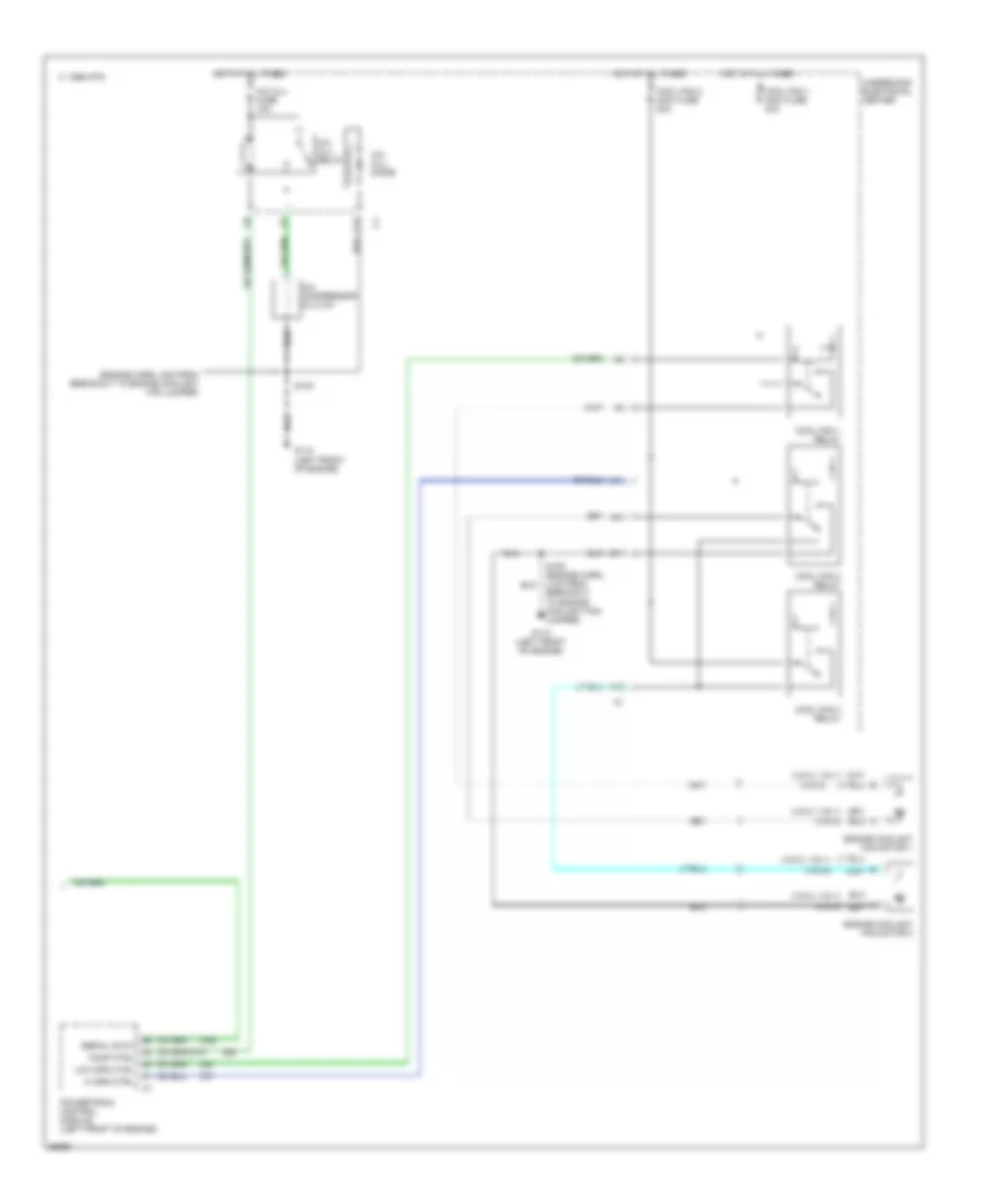
Air Conditioning Wiring Diagrams, Auto A/C (1 of 2) for Buick Century Custom 1997
 https://portal-diagnostov.com/license.html
Automotive Electricians Portal FZCO
Automotive Electricians Portal FZCO
https://portal-diagnostov.com/license.html
https://portal-diagnostov.com/license.html
Automotive Electricians Portal FZCO
Automotive Electricians Portal FZCO
List of elements for Air Conditioning Wiring Diagrams, Auto A/C (1 of 2) for Buick Century Custom 1997:
- (i/p harn, 34cm from heater-a/c control breakout)
- (i/p harn, 4cm from radio breakout)
- (i/p harness, 18cm from radio breakout)
- (i/p harness, 4cm from breakout to radio)
- (right side of i/p) g201
- +5 v
- A/c sol ctrl
- A/c solenoid
- Ambient outside temperature sensor (on center radiator support)
- Battery
- Bi-lev sol ctrl
- Bi-level solenoid
- Blower motor
- Blower motor control module (behind i/p, right of heater-a/c control module)
- C 1995 vftc
- C10
- C11
- C12
- C13
- C14
- C15
- C16
- D10
- D11
- D12
- D13
- D14
- D15
- D16
- Data link
- Data link connector (bottom of i/p, right of steering column)
- Def sol ctrl
- Defrost solenoid
- Fuse block
- G201 (right side of i/p)
- Ground
- Heater and a/c control (center of i/p)
- Heater solenoid
- High blower fuse 25a
- Hot at all times
- Hot in run
- Htr sol ctrl
- Hvac fuse 10a
- Ignition
- Inside air temperature sensor (right side of instrument cluster)
- Inside temp input
- Left electric actuator (left side of heater- a/c module)
- Lt elec actuator
- Motor drive
- Nca
- Outside temp input
- Radio
- Radio,hvac fuse 10a
- Rear defog enable
- Rear defogger system
- Recirc sol ctrl
- Recirc solenoid
- Red
- Right electric actuator (right side of heater- a/c module)
- Rt elec actuator
- S202 (i/p harness, right of steering column)
- S230
- S231
- S233
- S258
- Sensor ground
- Serial data
- Solid state
- Splice pack sp205
- Sun load input
- Sun load temperature sensor (top left of i/p)
- Tan
- Vacuum/ electric solenoid (behind i/p, right of plenum)
- Volt to blw ctrl
Air Conditioning Wiring Diagrams, Auto A/C (2 of 2) for Buick Century Custom 1997
List of elements for Air Conditioning Wiring Diagrams, Auto A/C (2 of 2) for Buick Century Custom 1997:
- (engine harn, 4cm from breakout to engine coolant fan jumper)
- (vin k, vin 1)
- (vin m)
- A/c clu diode
- A/c clu fuse 10a
- A/c clu relay
- A/c compressor clutch
- A10
- A11
- C 1995 vftc
- C11
- Comp ctrl
- Cool fan 1 maxi fuse 40a
- Cool fan 1 relay
- Cool fan 2 maxi fuse 30a
- Cool fan 2 relay
- Cool fan 3 relay
- Engine coolant fan motor 1
- Engine coolant fan motor 2
- F12
- G110 (left front of engine)
- Hi spd ctrl
- Hot at all times
- Low spd ctrl
- Powertrain control module (left front of engine)
- S105
- S105 (engine harn, 4 cm from breakout to engine coolant fan jumper)
- Serial data
- Underhood electrical center
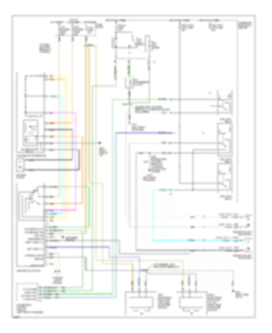
Air Conditioning Wiring Diagrams, Manual A/C for Buick Century Custom 1997
List of elements for Air Conditioning Wiring Diagrams, Manual A/C for Buick Century Custom 1997:
- (engine harn, 4cm from breakout to engine coolant fan jumper)
- (i/p harn, 4cm from breakout to radio)
- (i/p harness, 18cm from radio breakout)
- (vin k, vin 1)
- (vin m)
- A/c compressor clutch
- A/c clu diode
- A/c clu fuse 10a
- A/c clu relay
- A/c request sig
- A10
- A11
- Blower motor
- Blower motor relay
- Blower motor resistor
- Blower sw out
- C11
- Clutch req
- Comp ctrl
- Cool fan 1 maxi fuse 40a
- Cool fan 1 relay
- Cool fan 2 maxi fuse 30a
- Cool fan 2 relay
- Cool fan 3 relay
- Defogger on
- Defogger system
- Engine coolant fan motor 1
- Engine coolant fan motor 2
- F12
- Fuse block
- G110 (left front of engine)
- G201 (right side of i/p)
- Ground
- Heater-a/c control
- Hi spd ctrl
- High blower fuse 20a
- Hot at all times
- Hot in run
- Hvac fuse 10a
- Ignition
- Interior lights
- Interior lights system
- Lamp dim sig
- Left electronic actuator (left side of heater module)
- Left temp vlv
- Low blower fuse 20a
- Low spd ctrl
- Nca
- Off
- Powertrain control module (left front of engine)
- Right electronic actuator (w/ cj3) (right side of heater module)
- Right temp vlv
- S105
- S105 (engine harn, 4 cm from breakout to engine coolant fan jumper)
- S230
- S233
- Tan
- Underhood electrical center

 Čeština
 Dansk
Dansk Deutsch
 Ελληνικά
 English
 Español
 Suomi
Suomi Français
 Français
 עברית
עברית Hrvatski
 Magyar
 Italiano
 日本語
日本語 한국어
한국어 Nederlands
 Polski
 Português
 Português
 Română
 Русский
 Slovenčina
 Slovenščina
 Svenska
 Türkçe
 中文 (中国)