AIR CONDITIONING
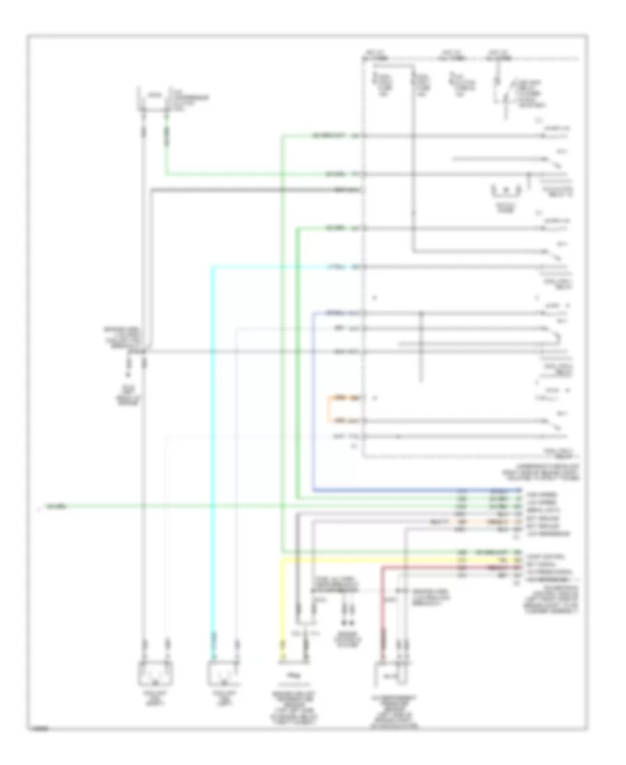
Automatic A/C Wiring Diagram (1 of 2) for Buick Century Custom 2000
 https://portal-diagnostov.com/license.html
Automotive Electricians Portal FZCO
Automotive Electricians Portal FZCO
https://portal-diagnostov.com/license.html
https://portal-diagnostov.com/license.html
Automotive Electricians Portal FZCO
Automotive Electricians Portal FZCO
List of elements for Automatic A/C Wiring Diagram (1 of 2) for Buick Century Custom 2000:
- (dash harn, 18 cm from radio breakout) s230
- (dash harn, 4 cm from breakout to radio)
- (dash harn, 4 cm from radio breakout)
- (on right side of of hvac module) vacuum/ electric solenoid
- (right side of dash) g201
- +5 v
- A/c sol ctrl
- A/c solenoid
- Ambient air temperature gauge sensor (behind front facia, mounted to radiator air baffle)
- Battery
- Bi-lev sol ctrl
- Bi-level solenoid
- Blower motor (in heater- a/c module)
- Blower motor control module (right side of heater-a/c module)
- Blower speed ctrl
- C10
- C11
- C12
- C13
- C14
- C15
- C16
- Cntrl in
- D10
- D11
- D12
- D13
- D14
- D15
- D16
- Data link connector (under left side of dash, right of steering column)
- Def sol ctrl
- Defrost solenoid
- Fuse block (behind right side of dash)
- Grd
- Ground
- Heater solenoid
- High blower fuse 25a
- Hot at all times
- Hot in run
- Htr sol ctrl
- Hvac control module
- Hvac fuse 10a
- Ignition
- Inside air temperature sensor (below right side of instrument cluster)
- Inside temp input
- Left air temperature actuator (left side of hvac module)
- Lt elec actuator
- Motor drive
- Nca
- Outside temp input
- Radio-hvac rfa-cluster cel tel fuse 15a
- Rear defog enable
- Rear defogger system
- Recirc sol ctrl
- Recirc solenoid
- Red
- Right air temperature actuator (right side of hvac module)
- Rt elec actuator
- S202 (dash harn, right of steering column)
- S231 (dash harn, 34 cm from heater-a/c control breakout)
- S233
- S258
- Sensor ground
- Serial data
- Solid state
- Sp205 (right side of steering column)
- Spd cntrl
- Sun load input
- Sun load temperature sensor (top of dash)
- Tan
Automatic A/C Wiring Diagram (2 of 2) for Buick Century Custom 2000
List of elements for Automatic A/C Wiring Diagram (2 of 2) for Buick Century Custom 2000:
- (engine harn, 4 cm from coolant fan breakout) s105
- (engine harn, 4 cm from pcm breakout)
- (fuel inj harn, near breakout to map sensor)
- +5v reference
- 3.1l
- 3.8l
- A/c compressor clutch coil
- A/c clu diode
- A/c clutch fuse 23 10a
- A/c clutch relay 15
- A/c press signal
- A/c refrigerent pressure sensor (left side of engine compt, on accumulator)
- A10
- A11
- C11
- Comp control
- Cool fan 1 fuse 15a
- Cool fan 2 fuse 15a
- Cool fan 1 relay
- Cool fan 2 relay
- Cool fan 3 relay
- Coolant fan (left)
- Coolant fan (right)
- E10
- Ect ground
- Ect signal
- Engine controls system
- Engine coolant temperature sensor (top left side of engine, below throttle body)
- F12
- G110 (left front of engine)
- High speed
- Hot at all times
- Ign main relay (closed in run or start)
- Low reference
- Low speed
- Powertrain control module (left front side of engine compt, in air cleaner assembly)
- S121
- S167
- Serial data
- Underhood fuse block (right side of engine compt, mounted to strut tower)
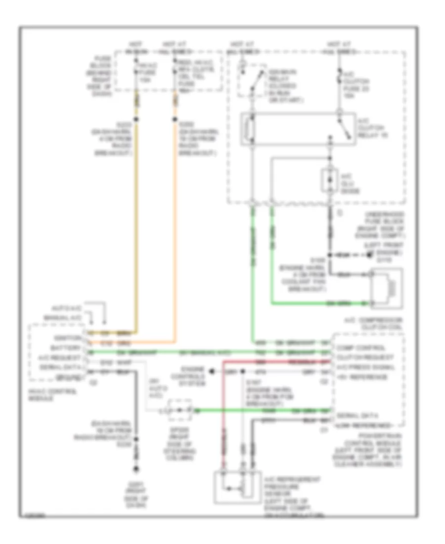
Compressor Wiring Diagram for Buick Century Custom 2000
List of elements for Compressor Wiring Diagram for Buick Century Custom 2000:
- (dash harn, 18 cm from radio breakout) s230
- (left front of engine) g110
- (w/ auto a/c)
- (w/ manual a/c)
- +5v reference
- A/c compressor clutch coil
- A/c clu diode
- A/c clutch fuse 23 10a
- A/c clutch relay 15
- A/c press signal
- A/c refrigerent pressure sensor (left side of engine compt, on accumulator)
- A/c request
- Auto a/c
- Battery
- C11
- C12
- Clutch request
- Comp control
- D12
- Engine controls system
- Fuse block (behind right side of dash)
- G201 (right side of dash)
- Ground
- Hot at all times
- Hot in run
- Hvac control module
- Hvac fuse 10a
- Ign main relay (closed in run or start)
- Ignition
- Low reference
- Manual a/c
- Powertrain control module (left front side of engine compt, in air cleaner assembly)
- Rdo, hvac, rfa clstr, cel tel fuse 10a
- S105 (engine harn, 4 cm from coolant fan breakout)
- S167 (engine harn, 4 cm from pcm breakout)
- S202 (dash harn, 19 cm from radio breakout)
- S233 (dash harn, 4 cm from radio breakout)
- Serial data
- Sp205 (right side of steering column)
- Underhood fuse block (right side of engine compt)
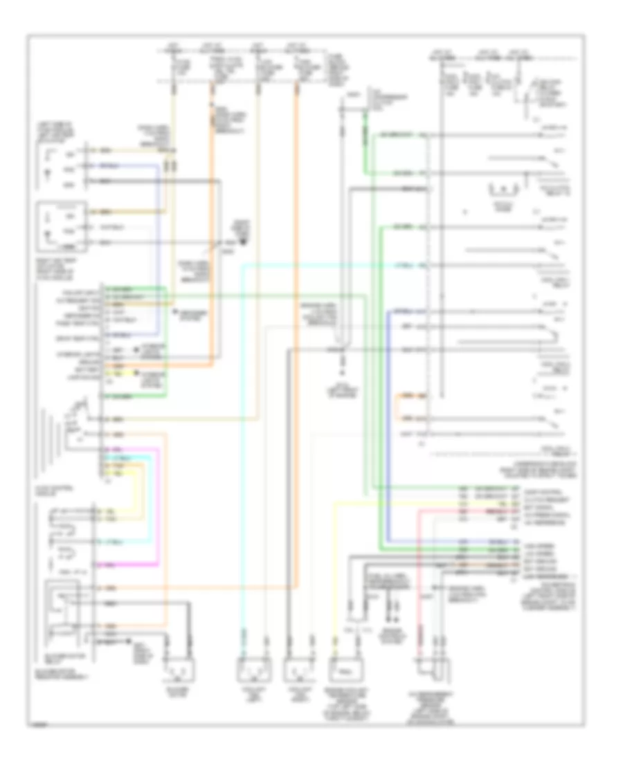
Manual A/C Wiring Diagram for Buick Century Custom 2000
List of elements for Manual A/C Wiring Diagram for Buick Century Custom 2000:
- (dash harn, 18 cm from radio breakout)
- (dash harn, 4 cm from radio breakout) s233
- (engine harn, 4 cm from coolant fan breakout)
- (engine harn, 4 cm from pcm breakout)
- (fuel inj harn, near breakout to map sensor)
- (left side of hvac module) left air temp actuator
- (right side of dash) g201
- +5v reference
- 3.1l
- 3.8l
- A/c compressor clutch coil
- A/c clu diode
- A/c clutch fuse 23 10a
- A/c clutch relay 15
- A/c press signal
- A/c refrigerent pressure sensor (left side of engine compt, on accumulator)
- A/c request sig
- A10
- A11
- Battery
- Blower motor
- Blower motor relay
- Blower motor resistor assembly
- C11
- Clutch request
- Comp control
- Cool fan 1 fuse 15a
- Cool fan 2 fuse 15a
- Cool fan 1 relay
- Cool fan 2 relay
- Cool fan 3 relay
- Coolant fan (left)
- Coolant fan (right)
- Defogger on
- Defogger system
- Drvr temp ctrl
- E10
- Ect ground
- Ect signal
- Engine controls system
- Engine coolant temperature sensor (top left side of engine, below throttle body)
- F12
- Fan off input
- Fuse block (behind right side of dash)
- G110 (left front of engine)
- G201 (right side of dash)
- Gnd
- Ground
- High blower fuse 30a
- High speed
- Hot at all times
- Hot in run
- Hvac control module
- Hvac fuse 10a
- Ign
- Ign main relay (closed in run or start)
- Ignition
- Interior lights
- Interior lights system
- Lamp dim sig
- Low blower fuse 20a
- Low reference
- Low speed
- Nca
- Nca nca
- Off
- Pass temp ctrl
- Pos
- Powertrain control module (left front side of engine compt, in air cleaner assembly)
- Rdo, hvac, rfa clstr, cel tel fuse 10a
- Right air temp actuator (right side of hvac module)
- S105
- S121
- S167
- S230
- Tan
- Underhood fuse block (right side of engine compt, mounted to strut tower)

 Čeština
 Dansk
Dansk Deutsch
 Ελληνικά
 English
 Español
 Suomi
Suomi Français
 Français
 עברית
עברית Hrvatski
 Magyar
 Italiano
 日本語
日本語 한국어
한국어 Nederlands
 Polski
 Português
 Português
 Română
 Русский
 Slovenčina
 Slovenščina
 Svenska
 Türkçe
 中文 (中国)