AIR CONDITIONING
Compressor Wiring Diagram for Chevrolet Astro 2004
 https://portal-diagnostov.com/license.html
Automotive Electricians Portal FZCO
Automotive Electricians Portal FZCO
https://portal-diagnostov.com/license.html
https://portal-diagnostov.com/license.html
Automotive Electricians Portal FZCO
Automotive Electricians Portal FZCO
List of elements for Compressor Wiring Diagram for Chevrolet Astro 2004:
- A/c comp fuse 10a
- A/c comp relay
- A/c compressor clutch
- A/c compressor clutch diode (in underhood fuse block)
- A/c enable relay
- A/c high pressure switch (rear of a/c comp)
- A/c low press
- A/c low pressure switch (on a/c accumulator)
- A/c request
- Bi-lv
- Blend
- Def
- G104 (lower left side of evaporative housing)
- Heat
- Hot at all times
- Hot in run
- Hot in run or start
- Htr-a/c fuse 12 20a
- Hvac control assembly
- I/p fuse block (behind left side of dash)
- Ign-e fuse 10a
- Max
- Norm
- Off
- Pnk
- Powertrain control module (below underhood fuseblock, on left side of firewall)
- S111 (engine harn, 17 cm from underhood fuse block breakout)
- S224 (i/p harn. 17 cm from body control module breakout)
- Underhood fuse block (left side of eng compt)
- Vent
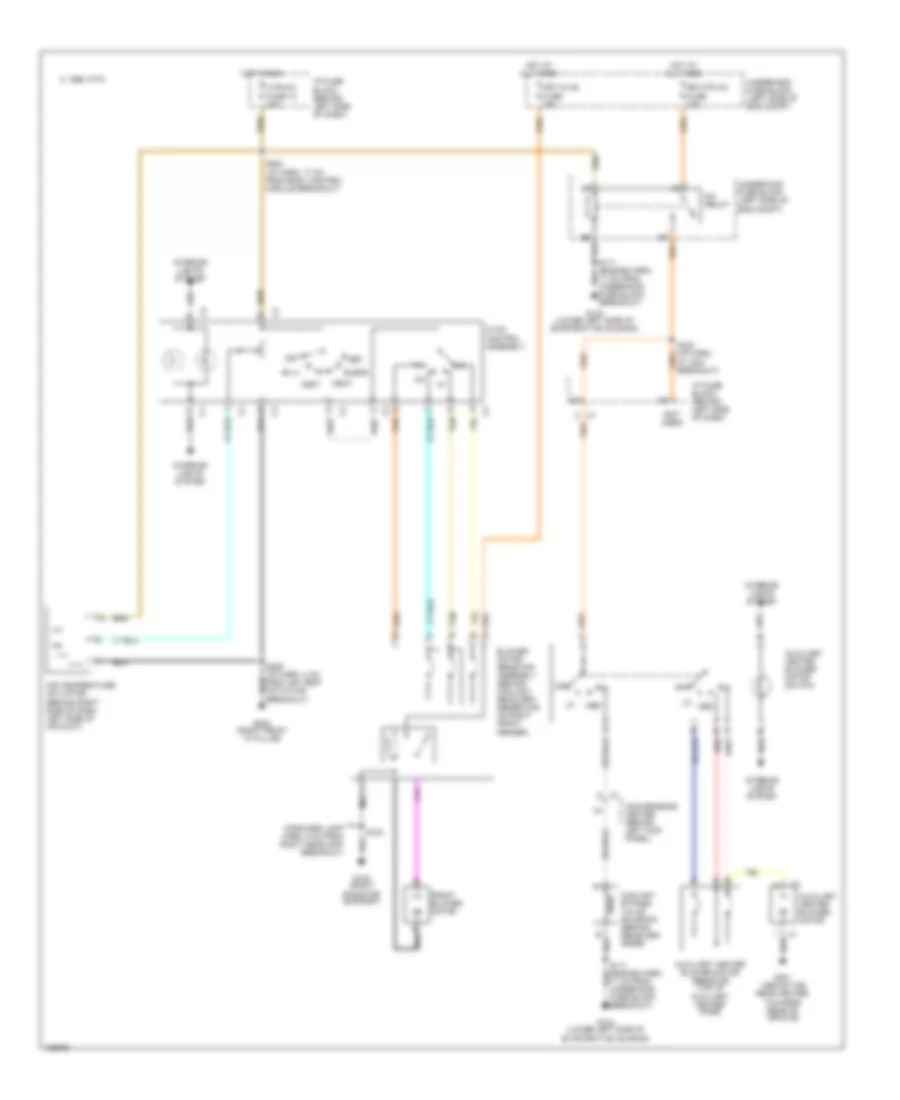
Heater Wiring Diagram for Chevrolet Astro 2004
List of elements for Heater Wiring Diagram for Chevrolet Astro 2004:
- (forward lamp harn, 8 cm from right headlamp breakout)
- (not used)
- 17 cm from underhood fuse block breakout)
- 1995 vftc c
- A/c relay
- Air temperature actuator (behind right side of dash, left side of air duct)
- Auxiliary heater blower motor
- Auxiliary heater blower motor resistor (top of auxiliary heater case)
- Auxiliary heater blower motor switch
- B red
- Bi-lv
- Blend
- Blower motor resistor assembly (behind coolant recovery reservoir, on right front fender)
- Convenience center (behind left kick panel)
- Coolant bypass valve solenoid (behind receiver/ drier)
- Def
- Front blower motor
- Frt hvac fuse 30a
- Fuse block breakout)
- G100 (right radiator support)
- G104 (lower left side of evaporative housing)
- G200 (right front "a" pillar)
- G301 (above the rear heater, towards rear of vehicle)
- Heat
- Hot at all times
- Hot in run
- Htr-a/c fuse 12 20a
- Hvac control assembly
- I/p fuse block (behind left side of dash)
- Interior lights system
- Med
- Off
- Rr htr a/c fuse 30a
- S100
- S224 (i/p harn. 17 cm from body control module breakout)
- S229 (i/p harn, 4 cm from air temp actuator breakout)
- Tan
- Underhood fuse block (left side of eng compt)
- Vent
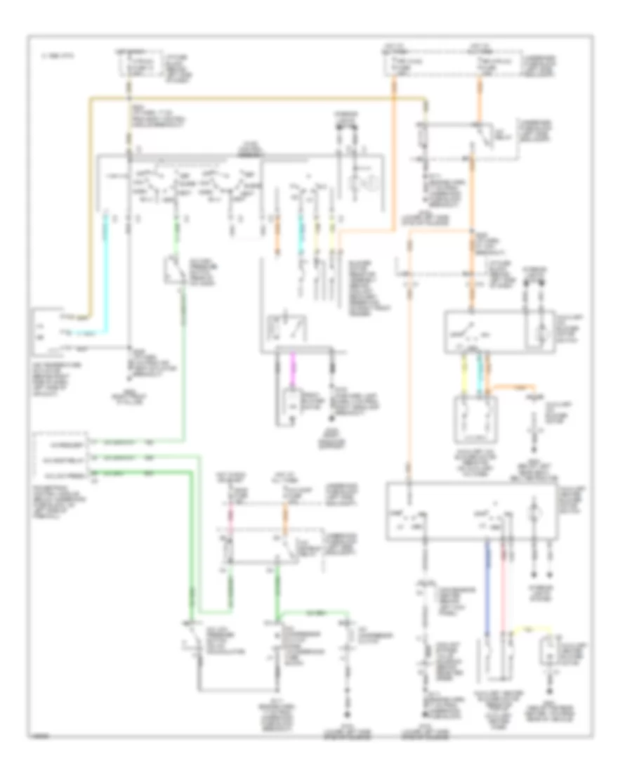
Manual A/C Wiring Diagram for Chevrolet Astro 2004
List of elements for Manual A/C Wiring Diagram for Chevrolet Astro 2004:
- 17 cm from underhood fuse block)
- 1995 vftc c
- A/c comp fuse 10a
- A/c comp relay
- A/c compressor clutch
- A/c compressor clutch diode (in underhood fuse block)
- A/c enable relay
- A/c high pressure switch (rear of a/c comp)
- A/c low press
- A/c low pressure switch (on a/c accumulator)
- A/c relay
- A/c request
- Air temperature actuator (behind right side of dash, left side of air duct)
- Auxiliary a/c blower motor
- Auxiliary a/c blower motor resistor (on auxiliary a/c case)
- Auxiliary a/c blower motor switch
- Auxiliary heater blower motor
- Auxiliary heater blower motor resistor (top of auxiliary heater case)
- Auxiliary heater blower motor switch
- B red
- Bi-lv
- Blend
- Blower motor resistor assembly (behind coolant recovery reservoir, on right front fender)
- C c3
- C10
- Convenience center (behind left kick panel)
- Coolant bypass valve solenoid (behind receiver/ drier)
- Def
- Front blower motor
- Frt hvac fuse 30a
- G100 (right radiator support)
- G104 (lower left side of evap housing)
- G200 (right front "a" pillar)
- G301 (above the rear heater, towards rear of vehicle)
- G404 (below left rear seat- belt retractor)
- Heat
- Hot at all times
- Hot in run
- Hot in run or start
- Htr-a/c fuse 12 20a
- Hvac control assembly
- I/p fuse block (behind left side of dash)
- Ign-e fuse 10a
- Interior lights system
- Max
- Med
- Norm
- Off
- Pnk
- Powertrain control module (below underhood fuse block, on left side of firewall)
- Rr htr a/c fuse 30a
- S100 (forward lamp harn, 8 cm from right headlamp breakout)
- S111 (engine harn, 17 cm from underhood fuse block breakout)
- S224 (i/p harn. 17 cm from body control module breakout)
- S229 (i/p harn, 4 cm from air temp actuator breakout)
- Tan
- Underhood fuse block (left side eng compt)
- Vent

 Čeština
 Dansk
Dansk Deutsch
 Ελληνικά
 English
 Español
 Suomi
Suomi Français
 Français
 עברית
עברית Hrvatski
 Magyar
 Italiano
 日本語
日本語 한국어
한국어 Nederlands
 Polski
 Português
 Português
 Română
 Русский
 Slovenčina
 Slovenščina
 Svenska
 Türkçe
 中文 (中国)