AIR CONDITIONING
Automatic A/C Wiring Diagram for Chevrolet Corvette 2004
 https://portal-diagnostov.com/license.html
Automotive Electricians Portal FZCO
Automotive Electricians Portal FZCO
https://portal-diagnostov.com/license.html
https://portal-diagnostov.com/license.html
Automotive Electricians Portal FZCO
Automotive Electricians Portal FZCO
List of elements for Automatic A/C Wiring Diagram for Chevrolet Corvette 2004:
- (at base of right "a" pillar) g202
- (base of right left "a" pillar)
- (breakout to right headlight door opening connector)
- (in dash harness, 5 cm from breakout to blower motor control module connector)
- (in forward light harness, 10 cm from breakout to a/c compressor clutch connector)
- (on top of right frame rail, behind right headlight)
- (right front of engine block)
- +5v
- 5 volt ref
- A/c clu relay
- A/c compressor clutch
- A/c compressor clutch diode (in forward lamp harness, near a/c clutch connector)
- A/c fuse 24 10a
- A/c on
- A/c refrigerant pressure sensor (on a/c high pressure line)
- A10
- A11
- Air inlet
- Air temperature actuator (left) (on left side of hvac module assembly)
- Air temperature actuator (right) (on right side of hvac module assembly)
- Air temperature sensor (inside) (right of steering column, (in air outlet vent)
- All times
- Ambient air temperature sensor (at right front of engine)
- B11
- Battery
- Blo mot fuse 51 30a
- Blower motor (under right side of dash)
- Blower motor control processor (behind right side of dash)
- Blwr mtr spd ctrl
- C10
- C11
- C12
- C13
- C14
- C15
- C16 illum
- Class 2 serial
- Computer data lines system
- Cool fan 1 fuse 49 30a
- Cool fan 1 relay
- Cool fan 2 fuse 46 30a
- Cool fan 2 relay
- Cool fan 3 fuse 14 10a
- Cool fan 3 relay
- D10
- D11
- D12
- D13
- D14
- D15
- D16
- Data line
- Data link connector (dlc) (under dash, below steering column)
- Def mode sol ctrl
- Defrost
- E10
- E11
- Ect sensor
- Engine coolant temperature (ect) sensor (on left side of engine, below generator)
- F11
- G10
- G102
- G102 (on top of right frame rail, behind right headlight)
- G11
- G202
- Gnd
- Ground
- Heater
- Hot at
- Hot at all times
- Hot in run
- Hvac con fuse 27 10a
- Hvac control module
- Hvac fuse 18 10a
- I/p fuse block (in right front footwell, mounted to toe board)
- Ign 3 volt
- In air temp sens
- Interior lights system
- Left cooling fan (behind left side of radiator)
- Low mode sol ctrl
- Mix-blend sol ctrl
- Mode closed
- Mode open
- Mtr cntrl
- Nca
- Or start
- Out air temp sens
- Pnk
- Powertrain control module (pcm) (behind right front fender, between wheelhouse & dash panel)
- Press sig
- Recirc sol ctrl
- Red
- Relay ctrl
- Right cooling fan (behind right side of radiator)
- S109
- S201 (in dash harness, 35 cm from hvac control head)
- S206
- S215 (in dash harness, 6.5 cm left of inflatable restraint dash breakout)
- Sens gnd
- Solid state
- Sp100
- Sp202 (in dash harness)
- Spd cntrl
- Star connector 1 (in dash harness, near left side of bcm)
- Sunload isig
- Sunload sensor (on top of dash, right side of defroster grille)
- Tan
- Temp dr ctrl
- Temp dr ctrl-aux
- Temp dr pos sig
- Temp dr pos-aux
- Underhood fuse block (on right side of engine compartment)
- Up mode sol ctrl
- Vacuum control assembly (on right side of hvac unit, right of blower motor)
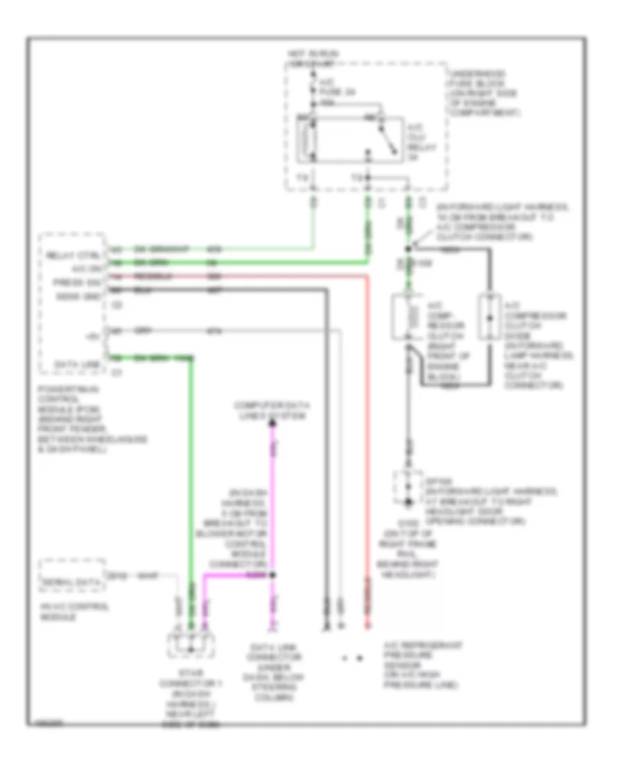
Compressor Wiring Diagram for Chevrolet Corvette 2004
List of elements for Compressor Wiring Diagram for Chevrolet Corvette 2004:
- (in dash harness, 5 cm from breakout to blower motor control module connector) s206
- (in forward light harness, 10 cm from breakout to a/c compressor clutch connector)
- +5v
- A/c clu relay
- A/c comp- ressor clutch (right front of engine block)
- A/c compressor clutch diode (in forward lamp harness, near a/c clutch connector)
- A/c fuse 24 10a
- A/c on
- A/c refrigerant pressure sensor (on a/c high pressure line)
- Computer data lines system
- D12
- Data line
- Data link connector (under dash, below steering column)
- G102 (on top of right frame rail, behind right headlight)
- Hot in run or start
- Hvac control module
- Nca
- Powertrain control module (pcm) (behind right front fender, between wheelhouse & dash panel)
- Press sig
- Relay ctrl
- S109
- Sens gnd
- Serial data
- Sp100 (in forward light harness, at breakout to right headlight door opening connector)
- Star connector 1 (in dash harness,) near left side of bcm)
- Underhood fuse block (on right side of engine compartment)

 Čeština
 Dansk
Dansk Deutsch
 Ελληνικά
 English
 Español
 Suomi
Suomi Français
 Français
 עברית
עברית Hrvatski
 Magyar
 Italiano
 日本語
日本語 한국어
한국어 Nederlands
 Polski
 Português
 Português
 Română
 Русский
 Slovenčina
 Slovenščina
 Svenska
 Türkçe
 中文 (中国)