AIR CONDITIONING
Compressor Wiring Diagram for Chevrolet SSR 2005
 https://portal-diagnostov.com/license.html
Automotive Electricians Portal FZCO
Automotive Electricians Portal FZCO
https://portal-diagnostov.com/license.html
https://portal-diagnostov.com/license.html
Automotive Electricians Portal FZCO
Automotive Electricians Portal FZCO
List of elements for Compressor Wiring Diagram for Chevrolet SSR 2005:
- (or 2288)
- 5v ref
- A/c compressor clutch (on a/c compressor)
- A/c fuse 30 10a
- A/c refrigerant pressure sensor (on high pressure hose connection to compressor)
- A/c relay
- A/c req sig
- Amx defrost
- C1 f3
- Cl rly ctrl
- Computer data lines system
- D11
- Defrost
- Engine control module (ecm) (left front side of engine compt)
- Evaporator temperature sensor (behind radio on top of hvac case)
- Flr
- Flt/defrost
- G100 (lower left front of engine)
- G200
- Hot at all times
- Hot in run or start
- Hvac control module
- Ign e fuse 23 10a
- Logic
- Low ref
- Mode switch
- Panel
- Panel/flr
- Roof/door module (rear center of passenger compt)
- S207 (i/p harness, 9 cm from hvac control module breakout)
- Sens sig
- Serial data
- Sp200 (right side of instrument cluster)
- Underhood fuse block (on left side of engine compt)
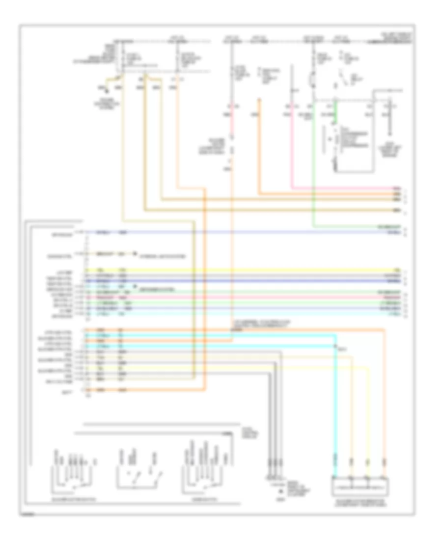
Manual A/C Wiring Diagram (1 of 2) for Chevrolet SSR 2005
List of elements for Manual A/C Wiring Diagram (1 of 2) for Chevrolet SSR 2005:
- (i/p harness, 15 cm from hvac control module breakout) s209
- (on left side of engine compt) underhood fuse block
- 5v ref
- A/c compressor clutch (on a/c compressor)
- A/c fuse 30 10a
- A/c relay
- A/c req sig
- B c6
- Batt
- Blower motor (lower right side of dash)
- Blower motor resistor (lower right side of dash)
- Blower motor switch
- Blower mtr ctrl
- C1 c1
- C1 f3
- C4 b2
- D11
- Defog sw sig
- Defogger system
- Defrost
- Defrost rear
- Dimming ctrl
- Dr ctrl a
- Dr ctrl b
- Dr pos sig
- Eng cool fan fuse 37 60a
- Flr
- Flt/defrost
- G100 (lower left front of engine)
- G200
- Gnd
- High
- Hot at all times
- Hot in run
- Hot in run or start
- Hvac 1 fuse 39 10a
- Hvac b dd unlock fuse 36 10a
- Hvac blwr fuse 45 40a
- Hvac control module
- Ign 3 voltage
- Ign e fuse 23 10a
- Interior lights system
- Logic
- Low ref
- Max defrost
- Med 1
- Med 2
- Med 3
- Mode switch
- Mtr high ctrl
- Off
- Panel
- Panel/flr
- Pnk
- Power distribution system
- Rear fuse block (rear center of passenger compt)
- Recirc
- Red
- S213
- Sp200 (right of instrument cluster)
- Tan
- Temp dr ctrl
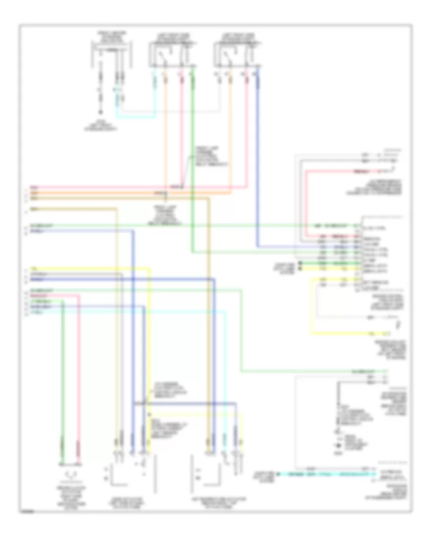
Manual A/C Wiring Diagram (2 of 2) for Chevrolet SSR 2005
List of elements for Manual A/C Wiring Diagram (2 of 2) for Chevrolet SSR 2005:
- (front center of engine) cooling fan
- (front lamp harness, 2.5 cm from cooling fan relay breakout)
- (i/p harness, 5 cm from hvac control module breakout)
- (left front side of engine compt) cooling fan 1 relay
- (left front side of engine compt) cooling fan 2 relay
- (or 2288)
- 5v ref
- A/c refrigerant pressure sensor (on high pressure hose connection to compressor)
- A/c req sig
- Air temperature actuator (behind radio, top of hvac case)
- Cl rly ctrl
- Computer data lines system
- Ect sens sig
- Engine control module (ecm) (left front side of engine compt)
- Engine coolant temperature (ect) sensor (on left front of engine)
- Evaporator temperature sensor (behind radio on top of hvac case)
- Fan rly ctrl
- Front lamp harness, 5 cm from cooling fan relay breakout)
- G105 (left front of engine compt)
- G200
- Logic
- Low ref
- Mode actuator (left side of dash, on hvac case)
- Nca
- Pnk
- Recirculation actuator (right side of dash, above blower motor)
- Roof/door module (rear center of passenger compt)
- S105
- S106
- S207 (i/p harness, 9 cm from hvac control module breakout)
- S208
- S212 (dash harness, 2.5 cm from ambient light sensor breakout)
- Sens sig
- Serial data
- Sp200 (right of instrument cluster)

 Čeština
 Dansk
Dansk Deutsch
 Ελληνικά
 English
 Español
 Suomi
Suomi Français
 Français
 עברית
עברית Hrvatski
 Magyar
 Italiano
 日本語
日本語 한국어
한국어 Nederlands
 Polski
 Português
 Português
 Română
 Русский
 Slovenčina
 Slovenščina
 Svenska
 Türkçe
 中文 (中国)