AIR CONDITIONING
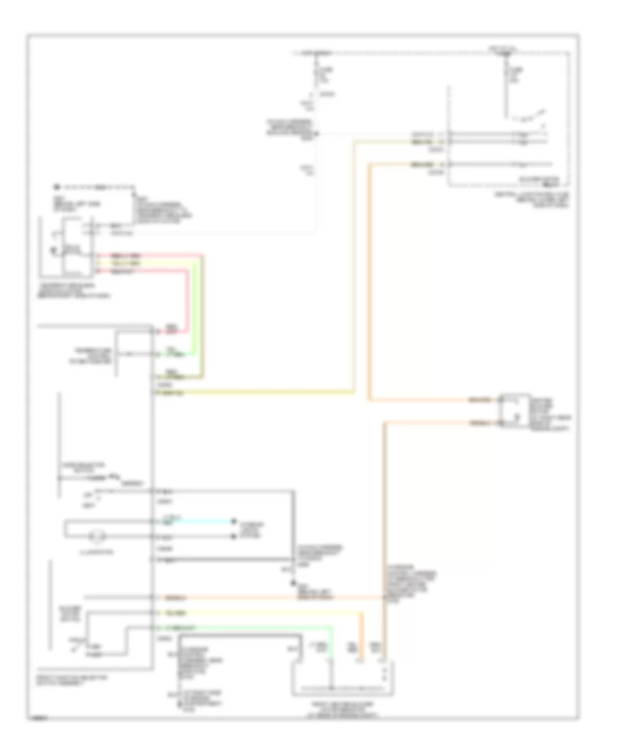
Automatic A/C Wiring Diagram (1 of 2) for Ford Cab & Chassis F350 Super Duty 2003
 https://portal-diagnostov.com/license.html
Automotive Electricians Portal FZCO
Automotive Electricians Portal FZCO
https://portal-diagnostov.com/license.html
https://portal-diagnostov.com/license.html
Automotive Electricians Portal FZCO
Automotive Electricians Portal FZCO
List of elements for Automatic A/C Wiring Diagram (1 of 2) for Ford Cab & Chassis F350 Super Duty 2003:
- (in main harness, near breakout for instrument cluster) s228
- (on vehicle floor, in left front footwell) g300
- A/c demand sig
- Air bag sliding contact
- Ambient air temperature sensor (on left front of engine compt)
- Ambient temp
- Batt
- Blend door actuator
- Blend door monitor
- Blend door sense +
- Blend door signal -
- Blow motor rly control
- Blower motor high
- Blower speed control signal return
- C228a
- C228b
- C270a
- Central junction box (cjb) (behind lower left side of dash)
- Diesel
- Electronic automatic temperature control (eatc) module (behind center of dash)
- Fan speed (+)
- Fan speed (-)
- Fuse 10a
- Gasoline
- Hot at all times
- Hot in run
- Ign
- Illumination
- In car temp sensor
- In-vehicle temperature sensor (behind left side of dash)
- Interior lights system
- Logic gnd
- Nca
- Powertrain control module (pcm) (on left side of firewall)
- Remote solenoid assembly
- Rest
- S114 (in engine control harness, near breakout for g101)
- Sensor return
- Sig rtn
- Solenoid assembly
- Speed control servo (in right side of engine compt)
- Speed controller
- Steering wheel contrlos
- Steering wheel radio switch
- Sunload sensor sig
- Temp (+)
- Temp (-)
- Temperature blend door actuator (behind right side of dash)
- Ubp diag
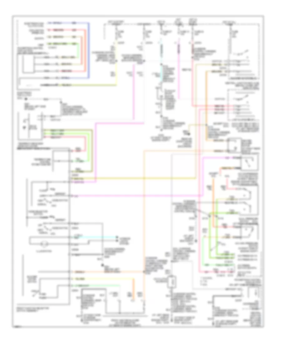
Automatic A/C Wiring Diagram (2 of 2) for Ford Cab & Chassis F350 Super Duty 2003
List of elements for Automatic A/C Wiring Diagram (2 of 2) for Ford Cab & Chassis F350 Super Duty 2003:
- (6.0l)
- (at left rear side of engine compt) g100
- (at left side of eng compt) g101
- (at right side of engine compt) g108
- (exc 6.0l)
- (exc 6.0l) (6.0l)
- (excursion)
- (ford super duty trucks)
- (in engine control harness, at breakout for auxiliary relay box 5) s171
- (in engine control harness, at breakout for front blower motor speed controller)
- (in engine control harness, at breakout for front blower motor speed controller) s158
- (in engine control harness, near breakout for g100) s122
- (in engine control harness, near breakout for g100) s124
- (in engine control harness, near breakout for g100) s173
- (in engine control harness, near breakout for g108) s180 s102 (in engine control harness, near breakout for g101)
- (in engine control harness, near breakout for powertrain control module)
- (on top center of dash)
- 5.4l/6.8l
- 6.0l
- 7.3l
- A/c clutch relay
- A/c clutch solenoid
- A/c compressor clutch diode
- A/c compressor cycling switch (in right rear of engine compartment, on a/c accumulator)
- A/c high pressure switch (in right side of engine compt)
- A/c press switch sig
- Auxiliary air conditioning circuit
- Auxiliary relay box 4 (exc 6.0l) auxiliary relay box 5 (6.0l) (at left rear side of engine compt)
- Blower motor relay
- C1381a
- C175
- C270a
- C270f
- C270g
- C270h
- Central junction box (cjb) (behind lower left side of dash)
- Data link connector (dlc) (behind left side of dash)
- Dual pressure (6.0l) (at front of engine)
- Exc 6.0l
- Except 6.0l
- For g108) s180
- Front blower motor speed controller (at right rear side of engine compt)
- Fuse 10 10a
- Fuse 107 40a
- Fuse 23 20a
- Fuse 27 15a
- G108 (at right side of engine compt)
- G202 (behind left side of dash)
- G300 (on vehicle floor, in left front footwell)
- Heater blower motor (at right rear side of engine compt)
- Hot at all times
- Hot in run
- Hot in start or run
- Instrument cluster)
- Nca
- Powertrain control module (pcm) (on left side of firewall)
- S106
- S116
- S119
- S157
- S162 (in engine control harness, near breakout for g100)
- S191 (in main harness, near breakout for c146)
- S218 (near breakout for instrument cluster)
- S247 (in main harness, near breakout to passenger air bag module)
- Sunload sensor
- Switch
- Vacuum pump motor (6.0l) (in right side of engine compartment)
Heater Wiring Diagram for Ford Cab & Chassis F350 Super Duty 2003
List of elements for Heater Wiring Diagram for Ford Cab & Chassis F350 Super Duty 2003:
- (in engine control harness, at breakout for front heater blower motor resistor) s152
- (in engine control harness, near breakout for g108) s180
- (in main harness, near breakout sunload sensor) s235
- (in main harness, near breakout to radio) s290
- Blower motor relay
- Blower motor switch
- C270a
- C270g
- C294a
- C294b
- C294c
- C294d
- Central junction box (cjb) (behind lower left side of dash)
- Defrost
- Floor
- Front function selector switch assembly
- Front heater blower motor resistor (at rear of engine compt)
- Fuse 10a
- Fuse 40a
- G201 (behind left side of dash)
- Heater blower motor (at right rear side of engine compt)
- High
- Hot at all times
- Hot in run
- Illumination
- Interior lights system
- Low
- Med
- Mix
- Mode selector switch
- Of engine compartment) g108
- Off
- S257 (in main harness, near breakout to temperature blend door actuator)
- Solid state
- Temperature blend door actuator (behind right side of dash)
- Temperature control potentiometer
- Vent
Manual A/C Wiring Diagram for Ford Cab & Chassis F350 Super Duty 2003
List of elements for Manual A/C Wiring Diagram for Ford Cab & Chassis F350 Super Duty 2003:
- (6.0l)
- (6.0l: in engine control harness, at breakout for auxiliary relay box 5) s171
- (at left rear side of engine compt) g100
- (at left side of eng compt) g101
- (at right side of engine compt) g108
- (exc 6.0l)
- (exc 6.0l) (6.0l)
- (except 6.0l) (6.0l)
- (in engine control harness, at breakout for front heater blower motor resistor) s152
- (in engine control harness, near breakout for g100) s122
- (in engine control harness, near breakout for g108) s180
- (in engine control harness, near breakout for left headlight) s109
- (in engine control harness, near breakout for powertrain control module)
- (in main harness, near breakout sunload sensor) s235
- (in main harness, near breakout to radio) s290
- 5.4l/6.8l
- 6.0l
- 7.3l
- A/c clutch relay
- A/c clutch solenoid
- A/c compressor clutch diode
- A/c compressor cycling switch (in right rear of engine compartment, on a/c accumulator)
- A/c high pressure switch (in right side of engine compt)
- A/c press sw in
- A/c press switch sig rtn
- Auxiliary relay box 4 auxiliary relay box 5 (at left rear side of engine compt)
- Blower motor relay
- Blower motor switch
- Breakout for g101)
- C1381a
- C1381c
- C175
- C270a
- C270f
- C270g
- C270h
- C294a
- C294b
- C294c
- C294d
- Central junction box (cjb) (behind lower left side of dash)
- Cooling fan speed sig
- Defrost
- Dual pressure (6.0l) (at front of engine)
- Electronic fan clutch (6.0l)
- Electronic fan clutch ctrl
- Exc 6.0l
- Except 6.0l
- Floor
- Front function selector switch assembly
- Front heater blower motor resistor (at rear of engine compt)
- Fuse 10 10a
- Fuse 10a
- Fuse 23 20a
- Fuse 27 15a
- Fuse 40a
- G108 (at right side of engine compt)
- G201 (behind left side of dash)
- Heater blower motor (at right rear side of engine compt)
- High
- Hot at all times
- Hot in run
- Hot in start or run
- Illumination
- Interior lights system
- Low
- Max
- Med
- Mix
- Mode selector switch
- Mode switch
- Nca
- Near breakout for g100)
- Normal
- Normal max
- Of engine compartment) g108
- Off
- Powertrain control module (pcm) (on left side of firewall)
- Rear air conditioning circuit (excursion)
- S106
- S116
- S119
- S162 (in engine control harness, near breakout for g100)
- S173 (in engine control harness, near breakout for g100)
- S180 (in engine control harness, near breakout for g108)
- S257 (in main harness, near breakout to temperature blend door actuator)
- Sig rtn
- Solid state
- Switch
- Temperature blend door actuator (behind right side of dash)
- Temperature control potentiometer
- Vacuum pump motor (diesel) (in right side of engine compt)
- Vent
- Vref

 Čeština
 Dansk
Dansk Deutsch
 Ελληνικά
 English
 Español
 Suomi
Suomi Français
 Français
 עברית
עברית Hrvatski
 Magyar
 Italiano
 日本語
日本語 한국어
한국어 Nederlands
 Polski
 Português
 Português
 Română
 Русский
 Slovenčina
 Slovenščina
 Svenska
 Türkçe
 中文 (中国)