AIR CONDITIONING
Manual A/C Wiring Diagram, with Stripped Chassis for Ford E450 Super Duty 2011
 https://portal-diagnostov.com/license.html
Automotive Electricians Portal FZCO
Automotive Electricians Portal FZCO
https://portal-diagnostov.com/license.html
https://portal-diagnostov.com/license.html
Automotive Electricians Portal FZCO
Automotive Electricians Portal FZCO
List of elements for Manual A/C Wiring Diagram, with Stripped Chassis for Ford E450 Super Duty 2011:
- (4.6l: engine control sensor wiring harness & fuel charge, near breakout to evap canister purge valve) (6.8l: engine control sensor wiring harness & fuel charge, in breakout to powertrain control module (pcm)) s172
- (not used)
- 4.6l & 5.4l
- 6.8l
- A/c clutch relay
- A/c compressor clutch field coil (lower right front of engine)
- Accr
- Accs
- Battery junction box (bjb) (left front of engine compt)
- Blower motor relay
- C134
- C1551b
- C1551e
- C175b
- C175e
- C2095
- C2280b
- C237
- C291
- Ce302
- Ch302
- Ch421
- Cht
- Customer access
- Cylinder head temperature sensor (front of left cylinder head)
- Engine controls system
- Except 5.4l
- Fuse 10a
- Fuse 40a
- Fuse 50a
- G100 (right side of engine compt)
- G101 (left front corner of engine compt)
- Hot at all times
- Hot in start or run
- Pcm power relay
- Pcmrc
- Powertrain control module (pcm) (center rear of engine compt)
- Re405
- S108
- S116
- S123
- S124
- S129
- Sigrtn
- Smart junction box (sjb) (left side of dash)
- Ve712
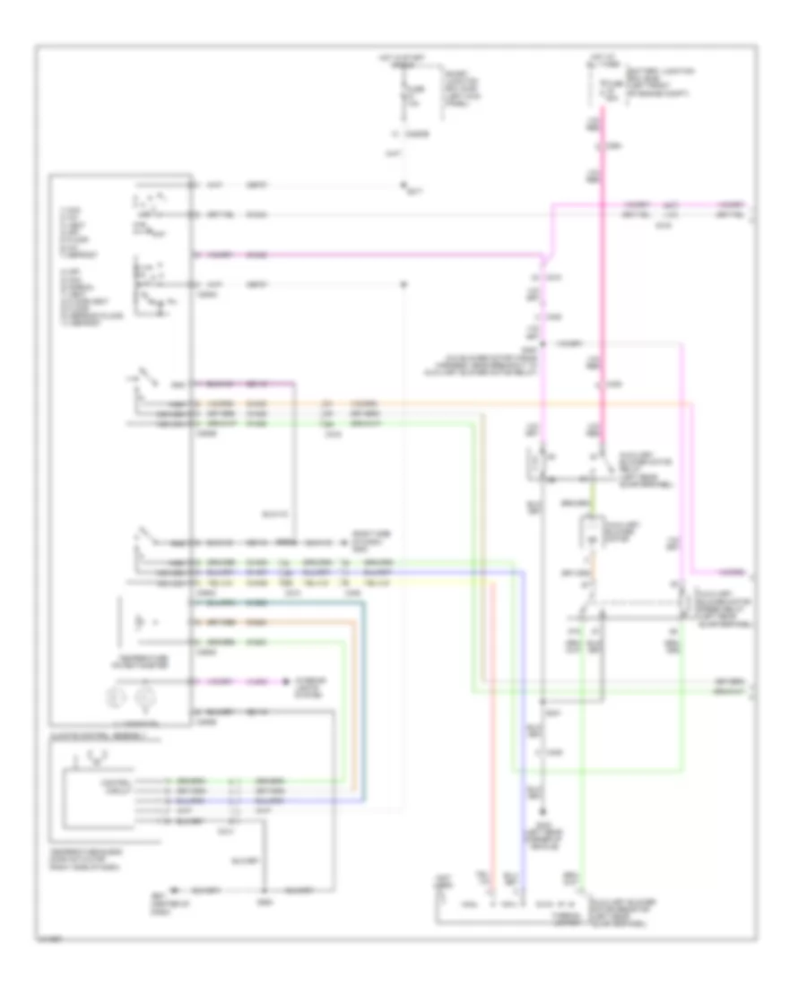
Manual A/C Wiring Diagram, without Stripped Chassis (1 of 2) for Ford E450 Super Duty 2011
List of elements for Manual A/C Wiring Diagram, without Stripped Chassis (1 of 2) for Ford E450 Super Duty 2011:
- (center of dash)
- (not used)
- (right side of dash) g200
- 0) off 5) max 6) normal 7) vent 8) floor/vent 9) floor 10) defrost/floor 11) defrost
- 1) max 2) a/c 3) vent 4) off 5) floor 6) mix 7) defrost
- 87a
- Auxiliary blower motor
- Auxiliary blower motor relay (left rear quarterpanel)
- Auxiliary blower motor resistor (left rear quarterpanel)
- Auxiliary blower motor speed relay (left rear quarterpanel)
- Battery junction box (bjb) (left front of engine compt)
- C210
- C214
- C219
- C2280b
- C264
- C294a
- C294b
- C294c
- C294d
- C294e
- C405
- Cbp37
- Ch202
- Ch203
- Ch204
- Ch428
- Ch429
- Ch430
- Ch434
- Ch435
- Cha06
- Cha07
- Cha08
- Circuit
- Climate control assembly
- Control
- Fuse 10a
- Fuse 50a
- G201
- G403 (left rear corner of vehicle)
- Gd115
- Gd116
- Gnd
- High
- Hot at all times
- Hot in start or run
- Illumination
- Interior lights system
- Mid high
- Mid low
- S217
- S264
- S265
- S400 (a/c blower motor wiring harness, near breakout to auxiliary blower motor relay)
- S401
- Smart junction box (sjb) (left kick panel)
- Temperature blend door actuator (right side of dash)
- Temperature potentiometer
- Thermal limiter
- Vlno4
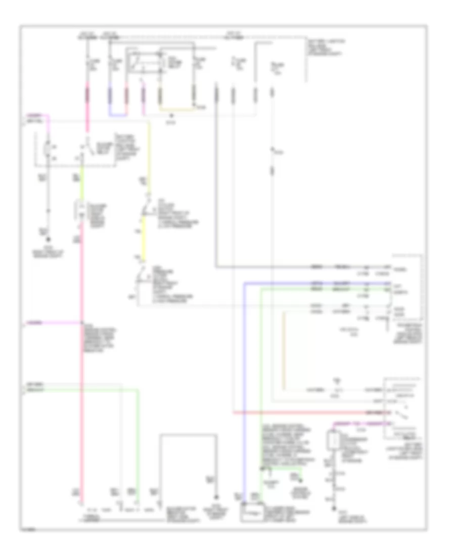
Manual A/C Wiring Diagram, without Stripped Chassis (2 of 2) for Ford E450 Super Duty 2011
List of elements for Manual A/C Wiring Diagram, without Stripped Chassis (2 of 2) for Ford E450 Super Duty 2011:
- (4.6l: engine control sensor wiring harness & fuel charge, near breakout to evap canister purge valve) (6.8l: engine control sensor wiring harness & fuel charge, in breakout to powertrain control module (pcm)) s172
- (left side of engine compt)
- (right front of engine compt)
- 1) normal pressure 2) high pressure
- 1) normal pressure 2) low pressure
- 4.6l & 5.4l
- 6.8l
- A/c clutch relay
- A/c compressor clutch field coil (lower right front of engine)
- A/c cycling switch
- Accr
- Accs
- Battery junction box (bjb) (left front
- Battery junction box (bjb) (left front of engine compt)
- Blower motor (right side of engine compt)
- Blower motor relay
- Blower motor resistor (right side of engine compt)
- C134
- C1551b
- C1551e
- C175b
- C175e
- Ce302
- Ch302
- Ch421
- Cht
- Compt)
- Cylinder head temperature sensor (front of left cylinder head)
- Engine controls system
- Except 5.4l
- Fuse 10a
- Fuse 40a
- Fuse 50a
- G100 (right front of engine compt)
- G101
- High pressure cutoff
- Hot at all times
- Of engine
- Of engine compt)
- Pcm power relay
- Pcmrc
- Powertrain control module (pcm) (left rear of engine compt)
- Re405
- S105 (engine control sensor wiring harness, near breakout to blower motor resistor)
- S116
- S123
- S124
- S129
- Sigrtn
- Switch (right front of engine compt)
- Thermal limiter
- Ve712

 Čeština
 Dansk
Dansk Deutsch
 Ελληνικά
 English
 Español
 Suomi
Suomi Français
 Français
 עברית
עברית Hrvatski
 Magyar
 Italiano
 日本語
日本語 한국어
한국어 Nederlands
 Polski
 Português
 Português
 Română
 Русский
 Slovenčina
 Slovenščina
 Svenska
 Türkçe
 中文 (中国)