AIR CONDITIONING
5.4L
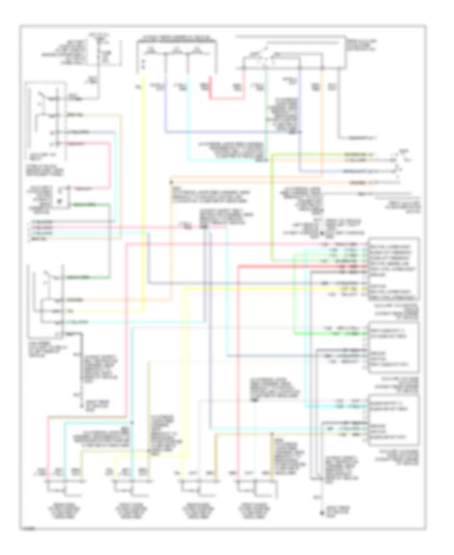
5.4L, Manual A/C Wiring Diagram (1 of 2) for Ford Excursion 2000
 https://portal-diagnostov.com/license.html
Automotive Electricians Portal FZCO
Automotive Electricians Portal FZCO
https://portal-diagnostov.com/license.html
https://portal-diagnostov.com/license.html
Automotive Electricians Portal FZCO
Automotive Electricians Portal FZCO
List of elements for 5.4L, Manual A/C Wiring Diagram (1 of 2) for Ford Excursion 2000:
- (2000)
- (2001)
- (center of dash) g206
- (in engine harness, near breakout to ground, right side of engine compartment, near battery) s180
- (in engine sensor harness, near breakout to blower motor resistor) s152
- (in main (in main harness, near breakout to data link connector (dlc)) (2001) s235
- (in main harness, near breakout to customer access) s290
- (in main harness, near breakout to park brake switch) s270
- (left rear of engine compartment, on firewall) g116
- (right side of engine compartment, near battery) g111
- 0.3 ohms
- 0.7 ohms
- 1.7 ohms
- 87a
- A/c
- A/c clutch cycling pressure switch (in right rear of engine compartment, on a/c accumulator)
- A/c clutch diode
- A/c clutch relay
- A/c compressor clutch solenoid (in right side of engine compartment)
- A/c head press switch
- Battery junction box (in left side of engine compartment, on top of wheelwell)
- Blend door actuator (behind right side of dash)
- Blend door potentiometer
- Blower motor (on right side of firewall)
- Blower motor relay
- Blower motor resistor (on right side of firewall, on plenum)
- Blower motor switch
- C225
- C242a
- C242a (or c242b)
- C242b
- C260
- C296
- C298
- Central junction box (behind lower left side of dash)
- Climate control illumination
- Cold
- Defrost
- Floor
- Floor/ defrost
- Function selector switch
- Fuse 10a
- Fuse 22 10a
- Fuse 24 (2001) fuse 5 (2000) 20a
- Fuse 24 10a
- Fuse 28 (2001) fuse 6 (2000) 15a
- Fuse 40a
- Harness, near breakout to brake pedal position (bpp) switch) s235 (2000)
- High
- Hot at all times
- Hot in run
- Hot in run or start
- Interior lights system
- Low
- Lt (in main harness, near breakout to 16 pin in-line connector, behind center of dash) s206
- Max a/c
- Med high
- Med low
- Mode selector switch
- Off
- Pan/flr
- Panel
- Powertrain control module (pcm) (on left side of firewall)
- Red
- Refrigerant containment switch (in right side of engine compartment)
- S123 (in engine harness, near breakout to 40 pin in-line connector, left of steering column)
- S257 (in main harness, near breakout to air bag diagnostic module)
- S287 (in main harness, near breakout to 6 pin in-line connector, below dash)
- S322 (in right safety belt retractor harness, near breakout to ground, right rear of vehicle)
- Side of engine compartment, near battery) s180
- Solid state
- W/auxiliary air conditioning
- Warm
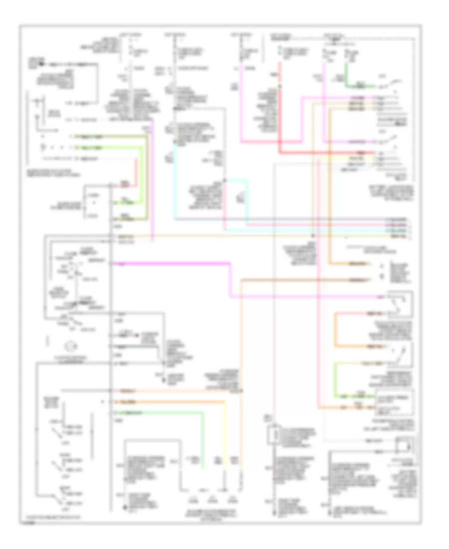
5.4L, Manual A/C Wiring Diagram (2 of 2) for Ford Excursion 2000
List of elements for 5.4L, Manual A/C Wiring Diagram (2 of 2) for Ford Excursion 2000:
- (front of vehicle near left vanity lamp) (w/o vent windows) g902
- (in interior lamps feed harness, near breakout to 2 pin connector in center of headliner) s935
- (in interior lamps feed harness, near breakout to 2nd row controller illumination in center of headliner) s924
- (in interior lamps feed harness, near breakout to 2nd row controller illumination in center of headliner) s925
- (in interior lamps feed harness, near breakout to rear blend potentiometer in center of headliner) s930
- (in interior lamps feed harness, near breakout to rear blend potentiometer in center of headliner) s931
- (in right rear corner of vehicle) auxiliary a/c blower motor resistor
- (in right safety belt retractor harness, near breakout to ground right rear of vehicle) s321
- (in right safety belt retractor harness, near breakout to ground, right rear of vehicle) s320
- (left rear of vehicle) (w/vent windows) g404
- (right rear of vehicle) g405
- 0.6 ohms
- 2.7 ohms
- 3.8 ohms
- 87a
- A/c mode act fbck
- Auxiliary a/c blend door actuator (in right rear corner of vehicle)
- Auxiliary a/c blower motor (in right rear corner of vehicle)
- Auxiliary a/c control module (in right rear corner of vehicle)
- Auxiliary a/c mode actuator (in right rear corner of vehicle)
- Auxiliary a/c relay
- Battery junction box (in left side of engine compartment, on top of wheelwell)
- Blend act feedback
- Blend dr act fbck
- Blend dr pot (+)
- Blend dr pot rtn
- Frnt ctrl wiper posit
- Frnt mode pot (+)
- Frnt mode pot rtn
- Front auxiliary a/c blower motor switch
- Front blend potentiometer (in center of headliner)
- Front mode potentiometer (in center of headliner)
- Fuse 40a
- Ground
- High speed auxiliary a/c relay (in left rear of vehicle)
- Hot at all times
- I/p relay block (behind dash, near instrument panel)
- Ignition
- Mode act feedback
- Off
- Rear auxiliary a/c blower motor switch
- Rear blend potentiometer (in center of headliner)
- Rear mode potentiometer (in center of headliner)
- Red
- Red/ pnk
- Rr ctrl sense line
- Rr ctrl wiper posit
- S927 (in interior lamps feed harness, near breakout to 2nd row controller illumination, in center of headliner)
- S928 (in interior lamps feed harness, near breakout to rear blend potentiometer in center of headliner)
- S929 (in interior lamps feed harness, near breakout to rear blend potentiometer in center of headliner)
6.8L
6.8L, Manual A/C Wiring Diagram (1 of 2) for Ford Excursion 2000
List of elements for 6.8L, Manual A/C Wiring Diagram (1 of 2) for Ford Excursion 2000:
- (2000)
- (2001)
- (center of dash) g206
- (in engine harness, near breakout to ground, right side of engine compartment, near battery) s180
- (in engine sensor harness, near breakout to blower motor resistor) s152
- (in main (in main harness, near breakout to data link connector (dlc)) (2001) s235
- (in main harness, near breakout to customer access) s290
- (in main harness, near breakout to park brake switch) s270
- (left rear of engine compartment, on firewall) g116
- (right side of engine compartment, near battery) g111
- 0.3 ohms
- 0.7 ohms
- 1.7 ohms
- 87a
- A/c
- A/c clutch cycling pressure switch (in right rear of engine compartment, on a/c accumulator)
- A/c clutch diode
- A/c clutch relay
- A/c compressor clutch solenoid (in right side of engine compartment)
- A/c head press switch
- Battery junction box (in left side of engine compartment, on top of wheelwell)
- Blend door actuator (behind right side of dash)
- Blend door potentiometer
- Blower motor (on right side of firewall)
- Blower motor relay
- Blower motor resistor (on right side of firewall, on plenum)
- Blower motor switch
- C225
- C242a
- C242a (or c242b)
- C242b
- C260
- C296
- C298
- Central junction box (behind lower left side of dash)
- Climate control illumination
- Cold
- Defrost
- Floor
- Floor/ defrost
- Function selector switch
- Fuse 10a
- Fuse 22 10a
- Fuse 24 (2001) fuse 5 (2000) 20a
- Fuse 24 10a
- Fuse 28 (2001) fuse 6 (2000) 15a
- Fuse 40a
- Harness, near breakout to brake pedal position (bpp) switch) s235 (2000)
- High
- Hot at all times
- Hot in run
- Hot in run or start
- Interior lights system
- Low
- Lt (in main harness, near breakout to 16 pin in-line connector, behind center of dash) s206
- Max a/c
- Med high
- Med low
- Mode selector switch
- Off
- Pan/flr
- Panel
- Powertrain control module (pcm) (on left side of firewall)
- Red
- Refrigerant containment switch (in right side of engine compartment)
- S123 (in engine harness, near breakout to 40 pin in-line connector, left of steering column)
- S257 (in main harness, near breakout to air bag diagnostic module)
- S287 (in main harness, near breakout to 6 pin in-line connector, below dash)
- S322 (in right safety belt retractor harness, near breakout to ground, right rear of vehicle)
- Side of engine compartment, near battery) s180
- Solid state
- W/auxiliary air conditioning
- Warm
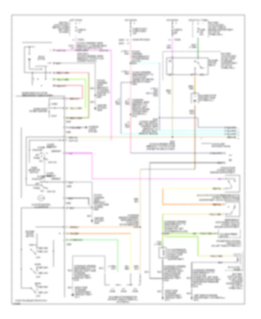
6.8L, Manual A/C Wiring Diagram (2 of 2) for Ford Excursion 2000
List of elements for 6.8L, Manual A/C Wiring Diagram (2 of 2) for Ford Excursion 2000:
- (front of vehicle near left vanity lamp) (w/o vent windows) g902
- (in interior lamps feed harness, near breakout to 2 pin connector in center of headliner) s935
- (in interior lamps feed harness, near breakout to 2nd row controller illumination in center of headliner) s924
- (in interior lamps feed harness, near breakout to 2nd row controller illumination in center of headliner) s925
- (in interior lamps feed harness, near breakout to rear blend potentiometer in center of headliner) s930
- (in interior lamps feed harness, near breakout to rear blend potentiometer in center of headliner) s931
- (in right rear corner of vehicle) auxiliary a/c blower motor resistor
- (in right safety belt retractor harness, near breakout to ground right rear of vehicle) s321
- (in right safety belt retractor harness, near breakout to ground, right rear of vehicle) s320
- (left rear of vehicle) (w/vent windows) g404
- (right rear of vehicle) g405
- 0.6 ohms
- 2.7 ohms
- 3.8 ohms
- 87a
- A/c mode act fbck
- Auxiliary a/c blend door actuator (in right rear corner of vehicle)
- Auxiliary a/c blower motor (in right rear corner of vehicle)
- Auxiliary a/c control module (in right rear corner of vehicle)
- Auxiliary a/c mode actuator (in right rear corner of vehicle)
- Auxiliary a/c relay
- Battery junction box (in left side of engine compartment, on top of wheelwell)
- Blend act feedback
- Blend dr act fbck
- Blend dr pot (+)
- Blend dr pot rtn
- Frnt ctrl wiper posit
- Frnt mode pot (+)
- Frnt mode pot rtn
- Front auxiliary a/c blower motor switch
- Front blend potentiometer (in center of headliner)
- Front mode potentiometer (in center of headliner)
- Fuse 40a
- Ground
- High speed auxiliary a/c relay (in left rear of vehicle)
- Hot at all times
- I/p relay block (behind dash, near instrument panel)
- Ignition
- Mode act feedback
- Off
- Rear auxiliary a/c blower motor switch
- Rear blend potentiometer (in center of headliner)
- Rear mode potentiometer (in center of headliner)
- Red
- Red/ pnk
- Rr ctrl sense line
- Rr ctrl wiper posit
- S927 (in interior lamps feed harness, near breakout to 2nd row controller illumination, in center of headliner)
- S928 (in interior lamps feed harness, near breakout to rear blend potentiometer in center of headliner)
- S929 (in interior lamps feed harness, near breakout to rear blend potentiometer in center of headliner)
7.3L DI TURBO DIESEL
7.3L DI Turbo Diesel, Manual A/C Wiring Diagram (1 of 2) for Ford Excursion 2000
List of elements for 7.3L DI Turbo Diesel, Manual A/C Wiring Diagram (1 of 2) for Ford Excursion 2000:
- (2000)
- (2001)
- (center of dash) g206
- (in engine harness, near breakout to 40 pin in-line connector, left of steering column) s168
- (in engine harness, near breakout to ground, right side of engine compartment, near battery) s180
- (in engine sensor harness, near breakout to blower motor resistor) s152
- (in main harness, near breakout to 16 pin in-line connector, behind center of dash) s206
- (in main harness, near breakout to brake pedal position (bpp) switch) s235 (2000)
- (in main harness, near breakout to customer access) s290
- (in main harness, near breakout to park brake switch) s270
- (left rear of engine compartment, on firewall) g116
- (right side of engine compartment, near battery) g111
- 0.3 ohms
- 0.7 ohms
- 1.7 ohms
- 87a
- A/c
- A/c clutch cycling pressure switch (in right rear of engine compartment, on a/c accumulator)
- A/c clutch diode
- A/c compressor clutch solenoid (in right side of engine compartment)
- A/c head press switch
- Battery junction box (in left side of engine compartment, on top of wheelwell)
- Blend door actuator (behind right side of dash)
- Blend door potentiometer
- Blower motor (on right side of firewall)
- Blower motor relay
- Blower motor resistor (on right side of firewall, on plenum)
- Blower motor switch
- C225
- C242a
- C242a (or c242b)
- C242b
- C260
- C296
- C298
- Central junction box (behind lower left side of dash)
- Climate control illumination
- Cold
- Defrost
- Floor
- Floor/ defrost
- Function selector switch
- Fuse 22 10a
- Fuse 24 10a
- Fuse 28 (2001) fuse 6 (2000) 15a
- Fuse 40a
- High
- Hot at all times
- Hot in run
- Interior lights system
- Low
- Lt (in engine harness, near breakout to ground, left rear of engine compartment, on firewall) s124
- Max a/c
- Med high
- Med low
- Mode selector switch
- Off
- Pan/flr
- Panel
- Powertrain control module (pcm) (on left side of firewall)
- Refrigerant containment switch (in right side of engine compartment)
- S235 (2001) (in main harness, near breakout to data link connector (dlc))
- S287 (in main harness, near breakout to 6 pin in-line connector, below dash)
- S322 (in right safety belt retractor harness, near breakout to ground, right rear of vehicle)
- Side of engine compartment, near battery) s180
- Solid state
- To air bag diagnostic module) s257
- Vacuum pump (in right side of engine compartment)
- W/auxiliary air conditioning
- Warm
7.3L DI Turbo Diesel, Manual A/C Wiring Diagram (2 of 2) for Ford Excursion 2000
List of elements for 7.3L DI Turbo Diesel, Manual A/C Wiring Diagram (2 of 2) for Ford Excursion 2000:
- (front of vehicle near left vanity lamp) (w/o vent windows) g902
- (in interior lamps feed harness, near breakout to 2 pin connector in center of headliner) s935
- (in interior lamps feed harness, near breakout to 2nd row controller illumination in center of headliner) s924
- (in interior lamps feed harness, near breakout to 2nd row controller illumination in center of headliner) s925
- (in interior lamps feed harness, near breakout to rear blend potentiometer in center of headliner) s930
- (in interior lamps feed harness, near breakout to rear blend potentiometer in center of headliner) s931
- (in right rear corner of vehicle) auxiliary a/c blower motor resistor
- (in right safety belt retractor harness, near breakout to ground right rear of vehicle) s321
- (in right safety belt retractor harness, near breakout to ground, right rear of vehicle) s320
- (left rear of vehicle) (w/vent windows) g404
- (right rear of vehicle) g405
- 0.6 ohms
- 2.7 ohms
- 3.8 ohms
- 87a
- A/c mode act fbck
- Auxiliary a/c blend door actuator (in right rear corner of vehicle)
- Auxiliary a/c blower motor (in right rear corner of vehicle)
- Auxiliary a/c control module (in right rear corner of vehicle)
- Auxiliary a/c mode actuator (in right rear corner of vehicle)
- Auxiliary a/c relay
- Battery junction box (in left side of engine compartment, on top of wheelwell)
- Blend act feedback
- Blend dr act (+)
- Blend dr act ctrl
- Blend dr pot rtn
- Frnt ctrl wiper posit
- Frnt mode pot rtn
- Front auxiliary a/c blower motor switch
- Front blend potentiometer (in center of headliner)
- Front mode pot (+)
- Front mode potentiometer (in center of headliner)
- Fuse 40a
- Ground
- High speed auxiliary a/c relay (in left rear of vehicle)
- Hot at all times
- I/p relay block (behind dash, near instrument panel)
- Ignition
- Mode act feedback
- Off
- Rear auxiliary a/c blower motor switch
- Rear blend potentiometer (in center of headliner)
- Rear mode potentiometer (in center of headliner)
- Red
- Red/ pnk
- Rr ctrl sense line
- Rr ctrl wiper posit
- S927 (interior lamps feed harness, near breakout to 2nd row controller illumination in center of headliner)
- S928 (in interior lamps feed harness, near breakout to rear blend potentiometer in center of headliner)
- S929 (in interior lamps feed harness, near breakout to rear blend potentiometer in center of headliner)

 Čeština
 Dansk
Dansk Deutsch
 Ελληνικά
 English
 Español
 Suomi
Suomi Français
 Français
 עברית
עברית Hrvatski
 Magyar
 Italiano
 日本語
日本語 한국어
한국어 Nederlands
 Polski
 Português
 Português
 Română
 Русский
 Slovenčina
 Slovenščina
 Svenska
 Türkçe
 中文 (中国)