AIR CONDITIONING
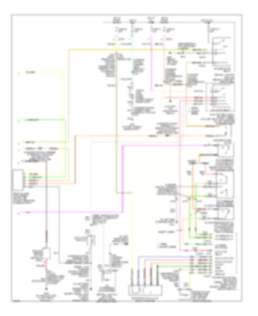
Automatic A/C Wiring Diagram (1 of 2) for Ford Excursion 2004
 https://portal-diagnostov.com/license.html
Automotive Electricians Portal FZCO
Automotive Electricians Portal FZCO
https://portal-diagnostov.com/license.html
https://portal-diagnostov.com/license.html
Automotive Electricians Portal FZCO
Automotive Electricians Portal FZCO
List of elements for Automatic A/C Wiring Diagram (1 of 2) for Ford Excursion 2004:
- (in main harness, near breakout for instrument cluster) s228
- (on vehicle floor, in left front footwell) g300
- A/c demand sig
- Air bag sliding contact (in steering column)
- Ambient air temperature sensor (on left front of engine compt)
- Ambient temp
- Batt
- Blend door actuator
- Blend door monitor
- Blend door sense +
- Blend door signal -
- Blow motor rly control
- Blower motor high
- Blower speed control signal return
- C1381a
- C218a
- C228a
- C228b
- C270a
- Central junction box (cjb) (behind lower left side of dash)
- Computer data lines system
- Cruise control system
- Diesel
- Electronic automatic temperature control (eatc) module (behind center of dash)
- Except diesel
- Fan speed (+)
- Fan speed (-)
- For instrument cluster)
- Fuse 10a
- Hot at all times
- Hot in run
- Ign
- Illumination
- In car temp sensor
- In-vehicle temperature sensor (behind left side of dash)
- Interior lights system
- Logic gnd
- Nca
- Powertrain control module (pcm) (left side of engine compt)
- Remote solenoid assembly (center of dash)
- Rest
- S191 (in main harness, near breakout for c146)
- Sensor return
- Sig rtn
- Solenoid assembly
- Speed control servo (in right side of engine compt)
- Speed controller
- Steering wheel controls
- Steering wheel radio switch
- Sunload sensor sig
- Temp (+)
- Temp (-)
- Temperature blend door actuator (behind right side of dash)
- Ubp diag
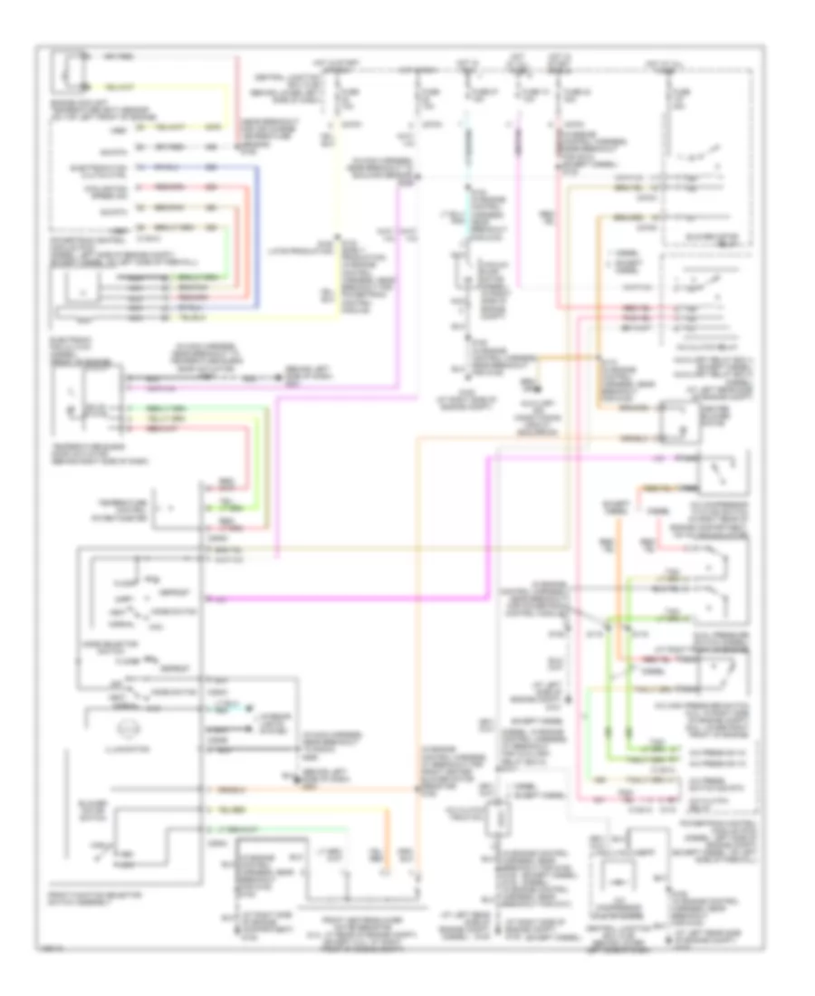
Automatic A/C Wiring Diagram (2 of 2) for Ford Excursion 2004
List of elements for Automatic A/C Wiring Diagram (2 of 2) for Ford Excursion 2004:
- (at left rear side of engine compt) g100
- (at left side of engine compt) g101
- (diesel)
- (diesel: engine control harness, at breakout for auxiliary relay box 5) s171
- (except diesel)
- (in engine control harness, at breakout for front blower motor speed controller)
- (in engine control harness, at breakout for front blower motor speed controller) s158
- (in engine control harness, near breakout for g100) (except diesel) s122
- (in engine control harness, near breakout for g100) s124
- (in engine control harness, near breakout for g100) s173
- (in engine control harness, near breakout for g108) s180
- (in engine control harness, near breakout for powertrain control module)
- (late production)
- (near breakout for instrument cluster)
- A/c clutch field coil
- A/c clutch relay
- A/c compressor clutch diode
- A/c compressor cycling switch (in right rear of engine compartment, on a/c accumulator)
- A/c high pressure switch (5.4l: in right side of engine compt) (6.8l: lower right front of engine)
- A/c press sw in
- A/c press switch sig
- Auxiliary air conditioning circuit
- Auxiliary relay box 4 (except diesel) auxiliary relay box 5 (diesel) (at left rear side of engine compt)
- Blower motor relay
- Breakout for g108) s180
- C1381a
- C1381c
- C175
- C270a
- C270f
- C270g
- C270h
- Central junction box (cjb) (behind lower left side of dash)
- Diesel
- Dual pressure switch (diesel) (at right front of engine)
- Electronic fan clutch (front of engine)
- Engine coolant temperature (ect) sensor (on top left front of engine)
- Except
- Except diesel
- Fan clutch ctrl
- Fan clutch sig
- For g100)
- Front blower motor speed controller (at right rear side of engine compt)
- Fuse 10 10a
- Fuse 107 40a
- Fuse 22 20a
- Fuse 23 20a
- Fuse 27 15a
- G108 (at right side of engine compt)
- G202 (behind left side of dash)
- G300 (on vehicle floor, in left front footwell)
- Heater blower motor
- Hot at all times
- Hot in run
- Hot in start or run
- Instrument cluster)
- Nca
- Powertrain control module (pcm) (diesel: left side of engine compt) (except diesel: on left side of firewall)
- S102 (in engine control harness, near breakout for g101)
- S106
- S116
- S119
- S157
- S192 (near breakout for air charge temperature sensor)
- S193 s123 (early production) (in engine control harness, near breakout for powertrain control module)
- S218
- Sens sig
- Sig rtn
- Sunload sensor (on top center of dash)
- Vacuum pump motor (diesel) (in right side of engine compt)
- Vref
Manual A/C Wiring Diagram for Ford Excursion 2004
List of elements for Manual A/C Wiring Diagram for Ford Excursion 2004:
- (at left rear side of engine compt) g100
- (at left side of engine compt) g101
- (at right side of engine compt) g108
- (behind left side of dash) g201
- (diesel)
- (except diesel)
- (except diesel) (diesel)
- (in engine control harness, at breakout for front heater blower motor resistor) s152
- (in engine control harness, near breakout for g108) s180
- (in engine control harness, near breakout for powertrain control module)
- (in main harness, near breakout to radio) s290
- (in main harness, near breakout to sunload sensor) s235
- (in main harness, near breakout to temperature blend door actuator) s257
- (near breakout for air charge temperature sensor) s192
- A/c clutch field coil
- A/c clutch relay
- A/c compressor clutch diode
- A/c compressor cycling switch (in right rear of engine compartment, on a/c accumulator)
- A/c high pressure switch (5.4l: in right side of engine compt) (6.8l: lower right front of engine)
- A/c press sw in
- A/c press switch sig rtn
- Auxiliary air conditioning circuit (excursion)
- Auxiliary relay box 4 (except diesel) auxiliary relay box 5 (diesel) (at left rear side of engine compt)
- Blower motor relay
- Blower motor switch
- Breakout for g101)
- C1381a
- C1381c
- C175
- C270a
- C270f
- C270g
- C270h
- C294a
- C294b
- C294c
- C294d
- Central junction box (cjb) (behind lower left side of dash)
- Cooling fan speed sig
- Defrost
- Diesel
- Dual pressure switch (diesel) (at right front of engine)
- Electronic fan clutch (diesel) (front of engine)
- Electronic fan clutch ctrl
- Engine coolant temperature (ect) sensor (on top left front of engine)
- Except
- Except diesel
- Floor
- Front function selector switch assembly
- Front heater blower motor resistor (5.4l: at rear of engine compt) (except 5.4l: at right front of engine compt)
- Fuse 10 10a
- Fuse 10a
- Fuse 23 20a
- Fuse 27 15a
- Fuse 40a
- G108 (at right side of engine compt)
- Heater blower motor
- High
- Hot at all times
- Hot in run
- Hot in start or run
- Illumination
- Interior lights system
- Low
- Max
- Med
- Mix
- Mode selector switch
- Mode switch
- Nca
- Normal
- Normal max
- Of engine compartment) g108
- Off
- Powertrain control module (pcm) (diesel: left side of engine compt) (except diesel: on left side of firewall)
- S106
- S116
- S119
- S123 (early production) (in engine control harness, near breakout for powertrain control module)
- S124 (in engine control harness, near breakout for g100)
- S173 (in engine control harness, near breakout for g100)
- S180 (in engine control harness, near breakout for g108)
- S193 (late production)
- Sig rtn
- Solid state
- Temperature blend door actuator (behind right side of dash)
- Temperature control potentiometer
- Vacuum pump motor (diesel) (in right side of engine compt)
- Vent
- Vref
Rear A/C Wiring Diagram for Ford Excursion 2004
List of elements for Rear A/C Wiring Diagram for Ford Excursion 2004:
- (at rear of vehicle roof) g901
- (at right "d" pillar) g403
- (at right rear side of engine compt) rear heater blower motor resistor
- (behind left side of dash) g201
- (behind left side of dash) g202
- (in interior illumination harness, near breakout for
- (in interior illumination harness, near breakout for rear auxiliary function selector switch assembly)
- (in main harness, near breakout for instrument cluster)
- (in rear vehicle interior harness, near breakout at right "d" pillar) s323
- (in rear vehicle interior harness, near breakout for rear power point) s320
- (near breakout for g901) s934
- (near breakout for rear auxiliary function selector switch assembly)
- (near breakout for rear power point) s322
- 87a
- Auto a/c
- Auxiliary a/c relay
- Auxiliary relay box 1 (behind glove box)
- Blend dr act ctrl
- Blend dr act posit sns
- Blend dr pot rtn
- Blend potentiometer
- Blower motor
- C270a
- C270d
- C270g
- C270j
- C294a
- C989a
- C989b
- C989c
- C989d
- C990a
- C990b
- C990c
- C990d
- Central junction box (cjb) (behind lower left side of dash)
- Def
- Floor
- Frnt mode pot rtn
- Front auxiliary function selector switch assembly
- Front function selector switch assembly
- Fuse 10a
- Fuse 15a
- Fuse 40a
- G901 (at rear of vehicle roof)
- Ground
- High
- High speed blower motor relay (at right "d" pillar)
- Hot at all times
- Hot in run
- Ignition
- Interior lights system
- Low
- Manual a/c
- Manual/ auto a/c circuit (excursion)
- Max
- Med high
- Med low
- Mix
- Mode act posit sig
- Mode act posit sns
- Mode dr act ctrl
- Mode dr act posit sns
- Mode potentiometer
- Normal
- Off
- Rear a/c control module (in right rear corner of vehicle, after "c" pillar)
- Rear a/c ctrl sig
- Rear auxiliary function
- Rear auxiliary function selector switch assembly
- Rear blend door actuator (in right rear corner of vehicle, after "c" pillar)
- Rear blower motor (in right rear corner of vehicle, after "c" pillar)
- Rear mode door actuator (in right rear corner of vehicle, after "c" pillar)
- Red
- Red/ pnk
- Relay
- S173 (near breakout for g100)
- S217
- S321 (in rear vehicle interior harness, near breakout for rear power point)
- S924
- S925
- S927 (in interior illumination harness, near breakout for rear auxiliary function selector switch assembly)
- S928
- S929
- S930
- S931
- S935 (near breakout for front auxiliary function selector switch assembly)
- Selector switch assembly)
- Switched ground
- Temp blend dr act feed
- Vent

 Čeština
 Dansk
Dansk Deutsch
 Ελληνικά
 English
 Español
 Suomi
Suomi Français
 Français
 עברית
עברית Hrvatski
 Magyar
 Italiano
 日本語
日本語 한국어
한국어 Nederlands
 Polski
 Português
 Português
 Română
 Русский
 Slovenčina
 Slovenščina
 Svenska
 Türkçe
 中文 (中国)