AIR CONDITIONING
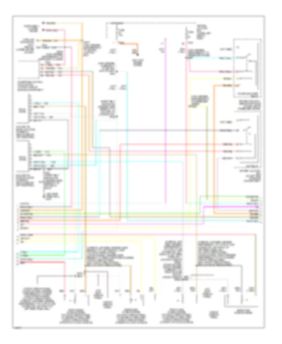
Automatic A/C Wiring Diagram (1 of 3) for Ford Expedition 2001
 https://portal-diagnostov.com/license.html
Automotive Electricians Portal FZCO
Automotive Electricians Portal FZCO
https://portal-diagnostov.com/license.html
https://portal-diagnostov.com/license.html
Automotive Electricians Portal FZCO
Automotive Electricians Portal FZCO
List of elements for Automatic A/C Wiring Diagram (1 of 3) for Ford Expedition 2001:
- (left rear wheelwell) g402
- (lower right kick panel) g203
- (main harness, near breakout to glove compartment lamp) s200
- (not used)
- (safety belt retractor harness, near breakout to rpo relay box 2) s424
- 87a
- A/c press cutoff sig
- Air bag sliding contact (at base of steering column)
- Amb temp sens input
- Ambient air temperature sensor (left front of engine compartment)
- Audio/climate control switch assembly
- Aux rly ctrl
- Auxiliary a/c control module (in rear of vehicle, behind left side panel)
- Battery
- Battery junction box (on left side of engine compartment)
- Blend door (wiper)
- Blend door 5v+
- Blend door act gnd
- Blend door actuator
- Blend door actuator (behind center of dash)
- Blower ctrl out
- Blower motor (on right side of engine compartment)
- Blower motor speed controller (behind right side of dash)
- Blower relay
- Blower/flasher relay block (behind center of dash)
- C205
- C242
- C243
- C280
- C281
- C282
- Central junction box (under left side of dash)
- Electronic automatic temperature control (eatc) module (behind center of dash)
- Front panel illum
- Fuse 10a
- Fuse 15a
- Fuse 40a
- Fuse 5a
- G203 (lower right kick panel)
- Ground
- Hot at all times
- Hot in run
- Hot in run or start
- Ignition
- In-car temp sens
- In-car temperature sensor (behind center of dash)
- Inst panel lp feed
- Interior lights system
- Nca
- Near breakout to instrument cluster)
- Red
- S134 (engine control sensor harness, near breakout to 40 pin in-line connector, left rear corner of engine compartment)
- S203 (main harness, near breakout to rpo relay block)
- S292 (main harness, near breakout to electronic automatic temperature control (eatc))
- S293 (main harness, near breakout to electronic automatic temperature control (eatc))
- Sensor input gnd
- Solid state
- Spc (+)
- Spc (-)
- Steering column assembly
- Steering whl sw
- Sunload sens input
- Sunload sensor (top right side of dash)
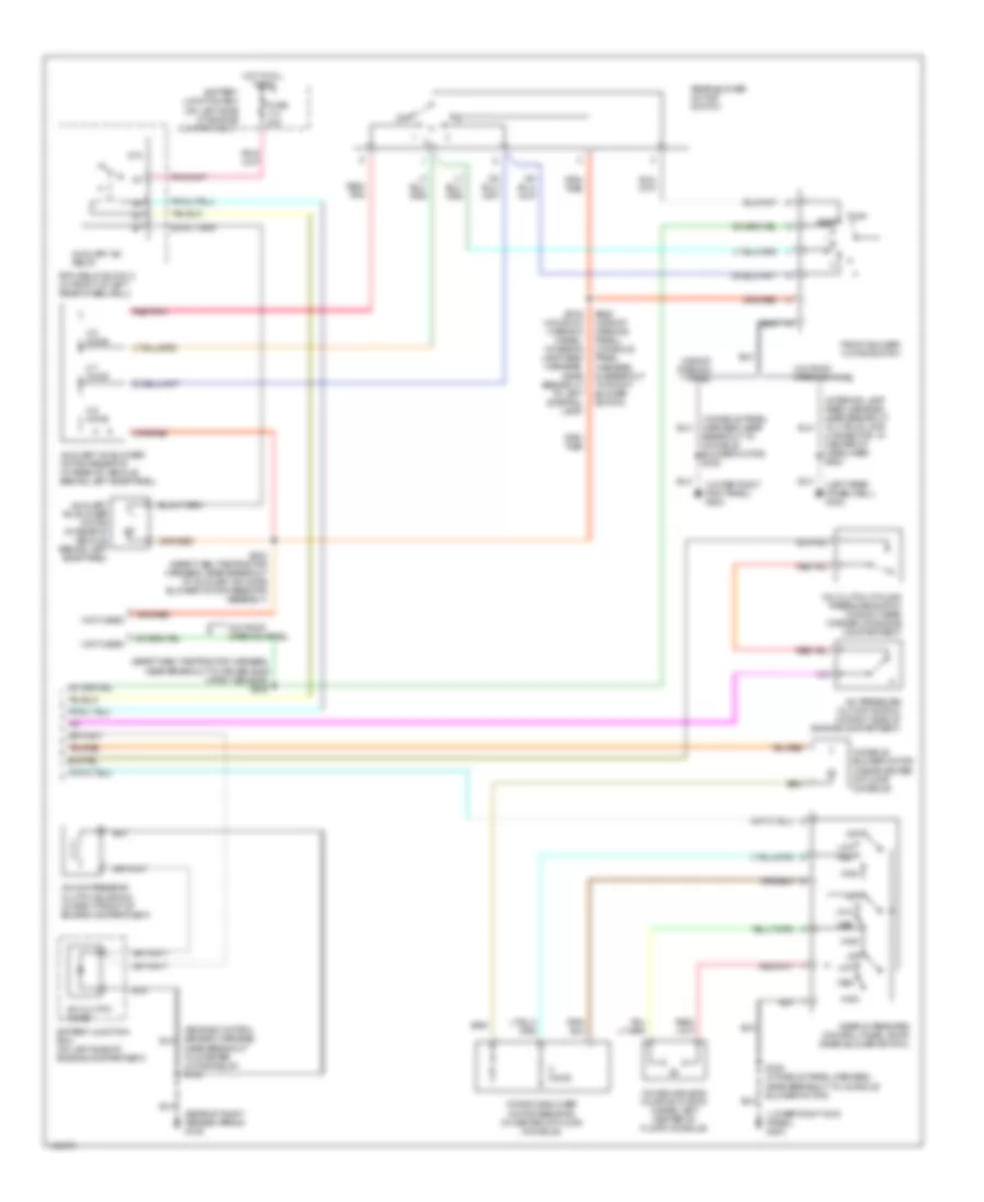
Automatic A/C Wiring Diagram (2 of 3) for Ford Expedition 2001
List of elements for Automatic A/C Wiring Diagram (2 of 3) for Ford Expedition 2001:
- (interior lamp feed harness, near breakout to 12 pin in-line connector, left front of left rear wheelwell) (w/o roof opening panel) (console panel wiring harness, in breakout to front blower switch) (w/roof opening panel)
- (interior lamp feed harness, near breakout to 16 pin in-line connector, left front of left rear wheelwell) (w/o roof opening panel) (console panel wiring harness, near breakout to cd changer) (w/roof opening panel) s352 (w/roof opening panel) s920 (w/o roof opening panel)
- (interior lamp feed harness, near breakout to left side rail lamp) (w/o roof opening panel) (console panel harness, near breakout to rear mode potentiometer) (w/roof opening panel) s340 (w/roof opening panel) s918 (w/o roof opening panel)
- (left rear wheelwell) g402
- (main harness, in breakout to central junction box) s228
- (main harness, near breakout to passenger airbag) s295
- (not used)
- (safety belt retractor harness, near breakout to auxiliary a/c mode switch) s422
- (w/o roof opening panel)
- (w/roof opening panel)
- (w/roof opening panel) (console panel harness, near breakout to rear mode potentiometer) (w/o roof opening panel) (interior lamp feed harness, near breakout to 12 pin in-line connector, left front of left rear wheelwell)
- Anti-lock brakes system
- Auxiliary a/c blend actuator (in rear of vehicle, behind left side panel)
- Auxiliary a/c mode actuator (in rear of vehicle, behind left side panel)
- Battery junction box (on left side of engine compartment)
- C242
- C243
- Central junction box (under left side of dash)
- Console blower relay
- Data link connector (dlc) (partial) (under center of dash)
- Front blend potentiometer (w/o roof opening panel) (in center of headliner) (w/roof opening panel) (in front of floor console)
- Front mode potentiometer (w/o roof opening panel) (in center of headliner) (w/roof opening panel) (in front of floor console)
- Fuse 10a
- Fuse 5a
- Hot in run
- Instrument cluster system
- Pnk/ (main harness, near breakout to passenger air bag) s296
- Powertrain control module (pcm) (on right side of engine compartment)
- Rear blend potentiometer (w/o roof opening panel) (in center of headliner) (w/roof opening panel) (in rear of floor console)
- Rear mode potentiometer
- Red
- Rpo relay block 1 (behind right side of dash, above passenger air bag)
- S2007 (main harness, near breakout to central junction box)
- S2008 (main harness, near breakout to instrument cluster)
- S339 s919
- S930 s921
- Solid state
- Tan/ red
- Wot relay
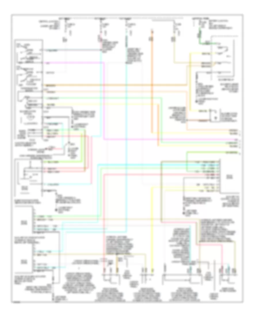
Automatic A/C Wiring Diagram (3 of 3) for Ford Expedition 2001
List of elements for Automatic A/C Wiring Diagram (3 of 3) for Ford Expedition 2001:
- (console panel harness, near breakout to console blower motor) s322
- (engine control sensor harness, near breakout to starter motor relay) s102
- (interior lamp feed harness, near breakout to 3 pin in-line connector, in center of headliner) s923
- (left rear wheelwell) g402
- (lower right kick panel) g203
- (not used)
- (rear of right fender apron) g105
- (safety belt retractor harness, near breakout to driver side impact sensor) s335
- 0.6 ohms
- 2.7 ohms
- 3.8 ohms
- 87a
- A/c clutch cycling pressure switch (in right rear corner of engine compartment)
- A/c clutch diode
- A/c compressor clutch solenoid (in right front of engine compartment)
- A/c pressure cut-off switch (in right side of engine compartment)
- Auxiliary a/c blower motor (in rear of vehicle, behind left side panel)
- Auxiliary a/c blower motor resistor (in rear of vehicle, behind left side panel)
- Auxiliary a/c relay
- Battery junction box (on left side of engine compartment)
- Console blend door actuator (inside left center of floor console)
- Console blower motor (inside center of floor console)
- Console blower motor resistor (in center of floor console)
- Front blower motor switch
- Fuse 30a
- High
- Hot at all times
- Low
- Med
- Off
- Ohms
- Rear
- Rear blower motor switch
- Rear integrated control panel (ricp) (rear blower switch)
- Red/ pnk
- Red/pnk
- Rpo relay block 2 (in front of left rear wheelwell)
- S322 (console panel harness, near breakout to console blower motor)
- S423 (safety belt retractor harness, near breakout to auxiliary a/c mode blower motor resistor assembly)
- S916 (w/o roof opening panel) (interior lamp feed harness, near breakout to left side rail lamp)
- S929 (w/roof opening panel) (console panel harness, in breakout to front blower switch)
- W/o roof opening panel
- W/roof opening panel
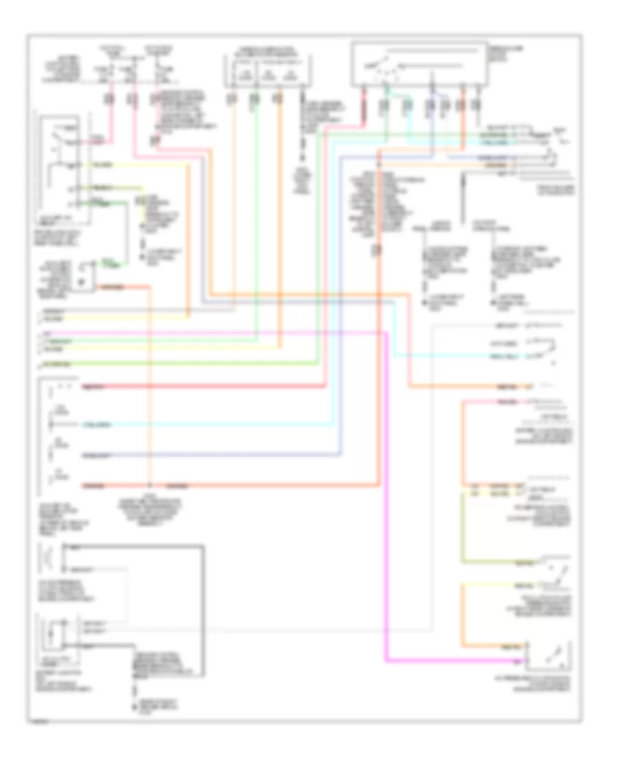
Manual A/C Wiring Diagram (1 of 2) for Ford Expedition 2001
List of elements for Manual A/C Wiring Diagram (1 of 2) for Ford Expedition 2001:
- (heater blower motor feed harness, in breakout to blower motor resistor) s125
- (interior lamp feed harness, near breakout to 12 pin in-line connector, left front of left rear wheelwell) (w/o roof opening panel) (console panel wiring harness, in breakout to front blower switch) (w/roof opening panel)
- (interior lamp feed harness, near breakout to 16 pin in-line connector, left front of left rear wheelwell) (w/o roof opening panel) (console panel wiring harness, near breakout to cd changer) (w/roof opening panel) s352 (w/roof opening panel) s920 (w/o roof opening panel)
- (interior lamp feed harness, near breakout to left side rail lamp) (w/o roof opening panel) (console panel harness, near breakout to rear mode potentiometer) (w/roof opening panel)
- (left rear wheelwell) g402
- (lower right kick panel) g203
- (main harness, near breakout to rpo relay block)
- (safety belt retractor harness, near breakout to auxiliary a/c mode switch) s422
- (w/o roof opening panel)
- (w/roof opening panel)
- (w/roof opening panel) (console panel harness, near breakout to rear mode potentiometer) (w/o roof opening panel) (interior lamp feed harness, near breakout to 12 pin in-line connector, left front of left rear wheelwell)
- (w/roof opening panel) (w/o roof opening panel)
- 87a
- Auxiliary a/c blend actuator (in rear of vehicle, behind left side panel)
- Auxiliary a/c control module (in rear of vehicle, behind left side panel)
- Auxiliary a/c mode actuator (in rear of vehicle, behind left side panel)
- Battery junction box (on left side of engine compartment)
- Blend door actuator (behind center of dash)
- Blend door potent- iometer
- Block)
- Blower motor (on right side of engine compartment)
- Blower motor switch
- Blower relay
- Blower/flasher relay block (behind center of dash)
- C217
- C218
- C219
- C220
- C242
- C243
- Central junction box (under left side of dash)
- Cold
- Def
- Def/flr
- Flasher relay block)
- Floor
- Flr & def
- Front blend potentiometer (w/o roof opening panel) (in center of headliner) (w/roof opening panel) (in front of floor console)
- Front mode potentiometer (w/o roof opening panel) (in center of headliner) (w/roof opening panel) (in front of floor console)
- Function selector switch assembly
- Fuse 23 10a
- Fuse 24 10a
- Fuse 40a
- Fuse 5 15a
- Fuse 5a
- High
- Hot at all times
- Hot in run
- Illumination
- Interior lights system
- Low
- Max a/c
- Med high
- Med low
- Mode selector switch
- Norm a/c
- Off
- Pan & flr
- Pan/flr
- Panel
- Pnk (main harness, near breakout to instrument cluster) s222
- Rear blend potentiometer (w/o roof opening panel) (in center of headliner) (w/roof opening panel) (in rear of floor console)
- Rear mode potentiometer
- Red
- S203
- S339 s919
- S340 s918
- S424 (safety belt retractor harness, near breakout to rpo relay box 2)
- S930 s921
- Solid state
- To rpo relay box 2) s424
- Warm
Manual A/C Wiring Diagram (2 of 2) for Ford Expedition 2001
List of elements for Manual A/C Wiring Diagram (2 of 2) for Ford Expedition 2001:
- (console panel harness, near breakout to console blower motor) s322
- (engine control sensor harness, near breakout to 40 pin in-line connector, left rear corner of engine compartment) s134
- (interior lamp feed harness, near breakout to 3 pin in-line connector, in center of headliner) s923
- (left rear wheelwell) g402
- (lower right kick panel) g203
- (main harness, near breakout to glove compartment lamp) s200
- (near blower motor) blower motor resistor
- (not used)
- (rear of right fender apron) g105
- .33 ohms
- .62 ohms
- 1.38 ohms
- 87a
- A/c clutch cycling pressure switch (in right rear corner of engine compartment)
- A/c clutch diode
- A/c compressor clutch solenoid (in right front of engine compartment)
- A/c pressure cut-off switch (in right side of engine compartment)
- Accs
- Auxiliary a/c blower motor (in rear of vehicle, behind left side panel)
- Auxiliary a/c blower motor resistor (in rear of vehicle, behind left side panel)
- Auxiliary a/c relay
- Battery junction box (on left side of engine compartment)
- Front blower motor switch
- Fuse 15a
- Fuse 30a
- G203 (lower right kick panel)
- Harness, near breakout to instrument cluster) s204
- Hot at all times
- Hot in run or start
- Off
- Powertrain control module (pcm) (on right side of engine compartment)
- Rear
- Rear blower motor switch
- Red/pnk
- Rpo relay block 2 (in front of left rear wheelwell)
- S102
- S423 (safety belt retractor harness, near breakout to auxiliary a/c mode blower resistor assembly)
- S916 (w/o roof opening panel) (interior lamp feed harness, near breakout to left side rail lamp)
- S929 (w/roof opening panel) (console panel wiring harness, in breakout to front blower switch)
- W/o roof opening panel
- W/roof panel opening
- Wot relay

 Čeština
 Dansk
Dansk Deutsch
 Ελληνικά
 English
 Español
 Suomi
Suomi Français
 Français
 עברית
עברית Hrvatski
 Magyar
 Italiano
 日本語
日本語 한국어
한국어 Nederlands
 Polski
 Português
 Português
 Română
 Русский
 Slovenčina
 Slovenščina
 Svenska
 Türkçe
 中文 (中国)