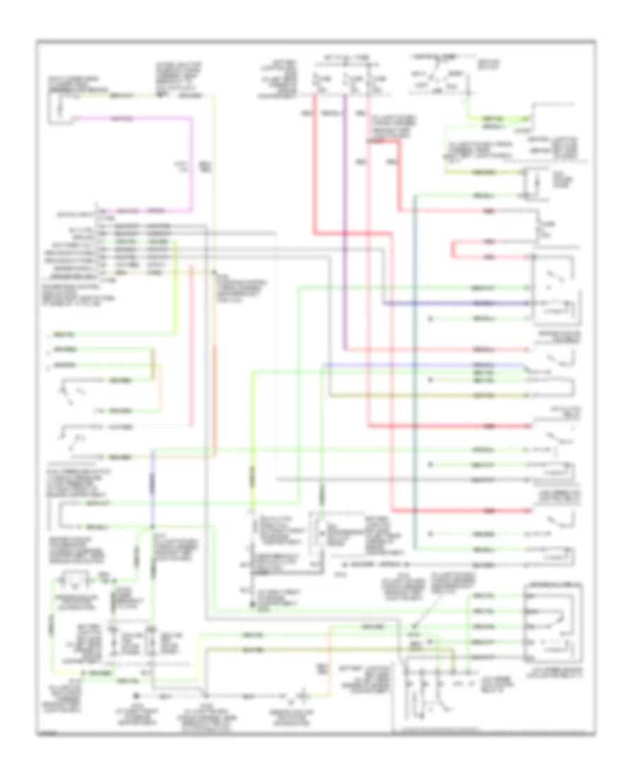
AIR CONDITIONING
Heater Wiring Diagram for Ford F450 Super Duty 2000
 https://portal-diagnostov.com/license.html
Automotive Electricians Portal FZCO
Automotive Electricians Portal FZCO
https://portal-diagnostov.com/license.html
https://portal-diagnostov.com/license.html
Automotive Electricians Portal FZCO
Automotive Electricians Portal FZCO
List of elements for Heater Wiring Diagram for Ford F450 Super Duty 2000:
- (at left ``a" pillar) g204
- (at right ``a" pillar) g203
- (in main wiring
- (in main wiring harness, near breakout for instrument cluster) s212
- 15-fa13
- 15s-fa38
- 29-fa13
- 29s-le10
- 31s-fa26
- 31s-hb22
- 31s-hb31
- 32-fa76
- 33-fa76
- 91-fa13
- 91s-fa20
- A/c compressor cycling switch (1: pressure increasing) (2: pressure decreasing) (in right rear corner of engine compartment)
- A/c on
- A/c switch
- A/c switch illumination
- Battery junction box (bjb) (in left rear corner of engine compartment)
- Blower motor resistor (behind center of dash)
- C270a
- C270e
- Central junction box (cjb) (behind left side of dash)
- De-icing switch
- Defogger system
- Fuse 40a
- Fuse 7.5a
- G203 (at right ``a" pillar)
- Harness, near breakout for instrument cluster) s206
- Heater blower motor (behind center of dash)
- Heater blower switch
- Heater control module (behind dash)
- High
- Hot at all times
- Hot in start or run
- Interior lights system
- Low speed
- Med high
- Med low
- Off
- Rear window heater on
- Rear window heater switch
- Rear window heater switch illumination
- Recirculation air actuator (behind right side of dash, next to blower motor)
- Recirculation on
- Recirculation switch
- Recirculation switch illumination
- S224 (in main wiring harness, near breakout for hazard flasher switch)
- Solid state
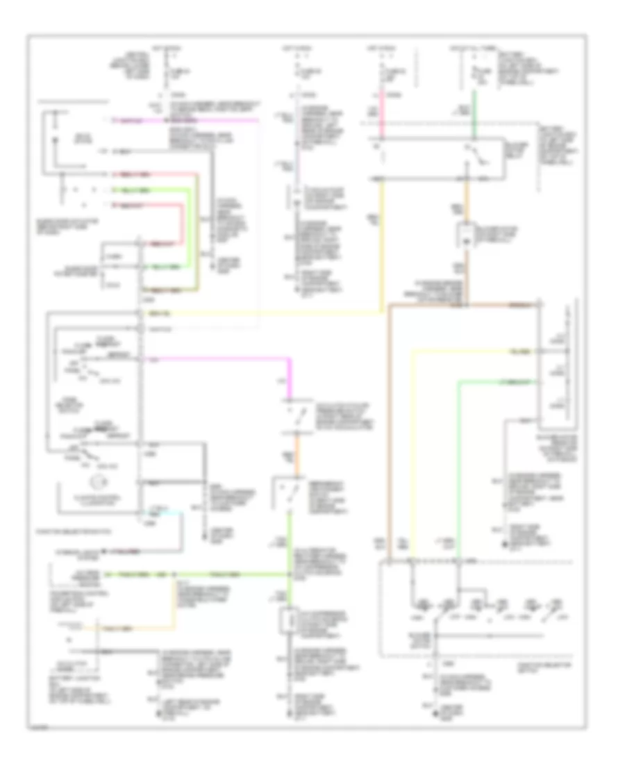
6.8L
6.8L, Manual A/C Wiring Diagram for Ford F450 Super Duty 2000
List of elements for 6.8L, Manual A/C Wiring Diagram for Ford F450 Super Duty 2000:
- (at right front of engine compartment) g102
- (in fuel shut-off solenoid wiring harness, near breakout to coil on plug 3) s198
- (in junction box wiring harness,
- (in junction box wiring harness, near battery junction box) s117
- (in junction box wiring harness, near breakout for c134)
- (on cylinder head) cylinder head temperature sensor
- 15s-re8
- 31s-fa11
- 31s-pa17
- 31s-pa21
- 31s-pa7
- 8-pa13
- 8-rj33
- 87a
- 9-re8
- A/c clutch field coil (at right front of engine compartment)
- A/c clutch relay
- A/c compressor clutch diode
- Acc
- Battery junction box (bjb) (in left rear corner of engine compartment)
- C175b
- C175e
- C270e
- Central junction box (cjb) (behind left side of dash)
- Cooling fan motor diode 1
- Cooling fan motor diode 2
- Dual pressure switch 1) normal pressure 2) high pressure (at right front of engine compartment)
- Engine cooling fan motor (on radiator)
- Engine cooling fan relay
- Engine cooling fan resistor (in front of engine compartment, near engine cooling fan)
- Fuse 10a
- Fuse 20a
- Fuse 30a
- Fuse 50a
- G102 (at right front of engine compartment)
- G104
- Ground
- Ground switched
- High speed fan control relay
- Hot at all times
- Ignition switch
- Lock
- Low speed cooling fan relay b
- Low speed engine cooling fan relay a
- Near battery junction box) s107
- Off
- Pcm power diode
- Power hold relay
- Powertrain control module (pcm) (behind right side of dash, at base of ``a" pillar)
- Red
- Rly ctrl
- Run
- S1002 (near breakout to c134)
- S109 (in junction box wiring harness, near breakout for a/c clutch field coil)
- S116 (in junction box wiring harness, near battery junction box)
- S118 (in junction box wiring harness, near battery junction box)
- S134
- S163 (in engine control wiring harness, near breakout for c144)
- Second cooling fan motor (on radiator)
- Sensor return
- Sensor signal
- Start
- Switch input
- Switched volt
7.3L DI TURBO DIESEL
7.3L DI Turbo Diesel, Manual A/C Wiring Diagram for Ford F450 Super Duty 2000
List of elements for 7.3L DI Turbo Diesel, Manual A/C Wiring Diagram for Ford F450 Super Duty 2000:
- (center of dash) g206
- (in alternator rectifier harness, near breakout to a/c compressor clutch solenoid) s125
- (in engine harness, near breakout to ground, left rear of engine compartment, on firewall) s124
- (in engine harness, near breakout to ground, right side of engine compartment, near battery) s180
- (in engine sensor harness, near breakout to blower motor resistor) s152
- (in main harness, near breakout to brake pedal position (bpp) switch) s235 (2000)
- (in main harness, near breakout to customer access) s290
- (right side of engine compartment, near battery) g111
- 0.3 ohms
- 0.7 ohms
- 1.7 ohms
- 87a
- A/c
- A/c clutch cycling pressure switch (in right rear of engine compartment, on a/c accumulator)
- A/c clutch diode
- A/c compressor clutch solenoid (in right side of engine compartment)
- A/c head pressure switch
- Battery junction box (in left side of engine compartment, on top of wheelwell)
- Blend door actuator (behind right side of dash)
- Blend door potentiometer
- Blower motor (on right side of firewall)
- Blower motor relay
- Blower motor resistor (on right side of firewall, on plenum)
- Blower motor switch
- C225
- C242a
- C242b
- C260
- C296
- C298
- Central junction box (behind lower left side of dash)
- Climate control illumination
- Cold
- Defrost
- Floor
- Floor/ defrost
- Function selector switch
- Fuse 22 10a
- Fuse 24 10a
- Fuse 28 10a
- Fuse 40a
- High
- Hot at all times
- Hot in run
- Interior lights system
- Low
- Max a/c
- Med high
- Med low
- Mode selector switch
- Off
- Pan/flr
- Panel
- Powertrain control module (pcm) (on left side of firewall)
- Refrigerant containment switch (in right side of engine compartment)
- S117 (in engine harness, near breakout to windshield wiper motor)
- S235 (2001) (in main harness, near breakout to data link connector (dlc))
- S290 (in main harness, near breakout to customer access)
- Solid state
- To air bag diagnostic module) s257
- Vacuum pump (in right side of engine compartment)
- Warm

 Čeština
 Dansk
Dansk Deutsch
 Ελληνικά
 English
 Español
 Suomi
Suomi Français
 Français
 עברית
עברית Hrvatski
 Magyar
 Italiano
 日本語
日本語 한국어
한국어 Nederlands
 Polski
 Português
 Português
 Română
 Русский
 Slovenčina
 Slovenščina
 Svenska
 Türkçe
 中文 (中国)