AIR CONDITIONING
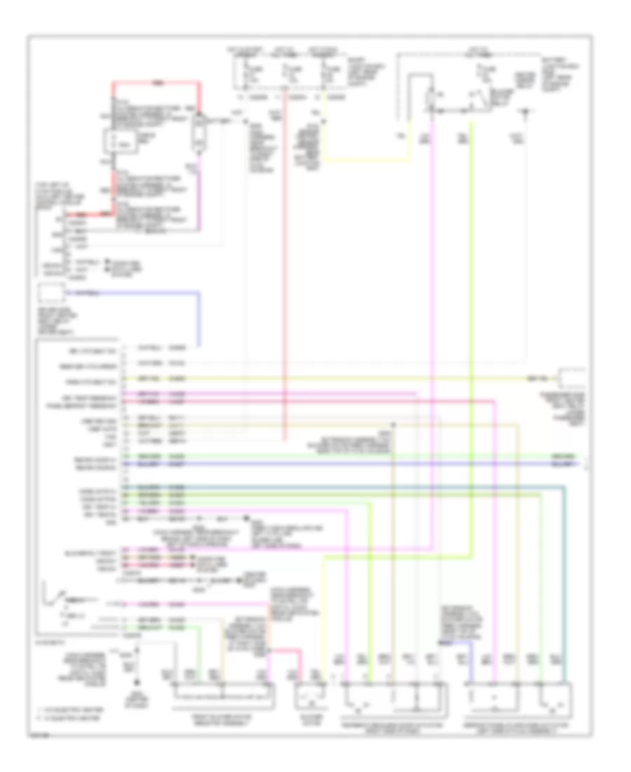
Automatic A/C Wiring Diagram (1 of 3) for Ford F450 Super Duty 2010
 https://portal-diagnostov.com/license.html
Automotive Electricians Portal FZCO
Automotive Electricians Portal FZCO
https://portal-diagnostov.com/license.html
https://portal-diagnostov.com/license.html
Automotive Electricians Portal FZCO
Automotive Electricians Portal FZCO
List of elements for Automatic A/C Wiring Diagram (1 of 3) for Ford F450 Super Duty 2010:
- (crew cab & regular cab: left "a" pillar) (super cab: left side of dash)
- (engine control sensor harness, near battery junction box)
- (extension assembly-a/c blower motor feed harness, near top of hvac housing) s250
- (extension assembly-a/c blower motor feed harness, near top of hvac housing) s251
- (main harness, near breakout behind left side of dash, left of radio opening)
- (top left of hvac module) auxiliary heater control module (ahcm)
- 150a
- Air inlet mode door actuator
- Ambient
- Battery
- Battery junction box (bjb) (left rear of engine compt)
- Blower command
- Blower motor relay
- Blower rly front
- Breakout to right front of engine compt)
- C2280a
- C2280b
- C2280e
- C228a
- C2357b
- C2463a
- C2463b
- C2463c
- Cable pro
- Cbp37
- Ch122
- Ch123
- Ch207
- Ch208
- Ch211
- Ch213
- Ch228
- Ch229
- Ch237
- Ch239
- Chs29
- Chs30
- Computer data lines system
- Defrost/panel/floor mode door actuator (left side of hvac assembly)
- Driver temperature blend door actuator (bottom of hvac assembly)
- Drv htd seat sw
- Drv sun load
- Drv temp a+
- Drv temp b-
- Drv temp feedback
- Fuse 10a
- Fuse 40a
- Fuse 5a
- G300
- Gd133
- Gnd
- Heated mirror relay
- Hot at all times
- Hot in run and acc
- Hot in start or run
- Hscan+
- Hscan-
- Hvac-datc
- Incar temp sn
- Lh111
- Mode actr a+
- Mode actr b-
- Mode actr feedback
- Mscan+
- Mscan-
- Nca
- Of engine compt)
- Pass htd seat sw
- Pass sun load
- Pass temp a+
- Pass temp b-
- Pass temp feedback
- Passenger temperature blend door actuator (top middle of hvac assembly)
- Rear def htd mirror
- Recirc a+
- Recirc b-
- Red
- Rh111
- S104
- S143 (alternator rectifier system harness, in nca
- S144 (alternator rectifier system harness, in breakout to right front red
- S145 (alternator rectifier system harness, in breakout to right front of engine compt)
- S206 (main harness, near breakout to right side of hvac housing)
- S224
- Sbp15
- Smart junction box (left rear of engine compt)
- Vbat
- Vdb06
- Vdb07
- Vh101
- Vh407
- Vh414
- Vh416
- Vh417
- Vh436
- Vh440
- Vh441
- Vign
- Vref act
- Vref rtn
- W/ electric heater
- W/o electric heater
Automatic A/C Wiring Diagram (2 of 3) for Ford F450 Super Duty 2010
List of elements for Automatic A/C Wiring Diagram (2 of 3) for Ford F450 Super Duty 2010:
- (center of dash) autolamp/sunload sensor
- (in extension
- (right side of hvac assembly) blower motor speed module
- (under driver's seat) driver side front heated seat relay
- (under passenger seat) passenger side front heated seat relay
- Ambient air temperature sensor (right front of engine compt)
- Assembly-a/c blower motor feed harness, at right side of hvac case)
- Blower motor
- Ch218
- Ch402
- G300 (crew cab & regular cab: left "a" pillar) (super cab: left side of dash)
- G302 (behind center of dash, behind audio control module)
- Gd179
- Gnd
- Headlights system
- In vehicle temperature sensor (left side of dash)
- S210 (main harness, near breakout behind audio control module)
- S224 (main harness, near breakout behind left side of dash, left of radio opening)
- S257
- S308
- S326 (crew cab: body main harness, near breakout to left "a" pillar) super cab: body main harness, near breakout behind left side of dash)
- Set- point
- Solid state control
- Vh101
- Vmot+
- Vmot-
Automatic A/C Wiring Diagram (3 of 3) for Ford F450 Super Duty 2010
List of elements for Automatic A/C Wiring Diagram (3 of 3) for Ford F450 Super Duty 2010:
- (diesel)
- (diesel) (gas)
- (diesel) engine coolant temperature (ect) sensor
- (diesel: engine control sensor harness, near breakout to right front of engine, on top) (5.4l: engine control sensor & fuel charge harness, near breakout to rear right of engine, on top) (6.8l: engine control sensor & fuel charge harness, near breakout to rear left of engine, on top)
- (engine control sensor & fuel charge harness, near breakout to right front of engine, on top) s133
- (engine control sensor harness, near battery junction box)
- (engine control sensor harness, near breakout to center front of engine compt)
- (engine control sensor harness, near breakout to left front corner of vehicle)
- (front of engine)
- (gas)
- (right rear of engine compt) (gas) a/c cycling switch
- A/c clutch diode
- A/c clutch relay
- A/c compressor field coil
- A/c cycling switch
- Accr
- Accs
- Acpsw
- Battery junction box (bjb) (left rear of engine compt)
- Brake pressure switch (bottom of master cylinder)
- C1232b
- C1232e
- C175b
- C175e
- Ce237
- Cec11
- Ch302
- Ch421
- Ch425
- Cht
- Cylinder head temperature sensor (6.8l: right cylinder head) (5.4l: rear of block, under intake)
- Diesel
- Dual pressure switch (diesel) (right front of engine)
- Ect
- Electric fan clutch (front of engine)
- Engine controls system
- Fcv
- Fuse 10a
- Fuse 20a
- Fuse 50 (gas) 30a fuse 39 (diesel) 50a
- G103 (right rear of engine compt)
- G108 (left rear of engine compt)
- Gas
- Gd119
- Gnd
- High pressure cutoff switch (right side of engine compt)
- Hot at all times
- Kapwr
- Mpr (pcm-rc)
- Nca fcv
- Nca gnd
- Nca sig
- Nca vbpwr
- Nca vpwr
- Near breakout to left front of frame)
- Pcm power relay
- Powertrain control module (pcm) (at left side of firewall)
- Re405
- S1008 (engine control sensor harness, near breakout to right rear of engine compt)
- S1009 (engine control sensor harness, near breakout to right front of engine, on top)
- S1010 (engine control sensor harness, near breakout to right front of engine, on top)
- S1013 (engine control sensor harness, near breakout to right front of engine, on top)
- S114
- S115
- S117 (diesel)
- S120
- S128 (engine control sensor harness, in breakout to master cylinder)
- S154 (gas)
- S158 (gas)
- Sbb36
- Sig
- Sig rtn
- Sigrtne
- Vbpwr
- Ve712
- Ve716
- Vec03
- Vec10
Manual A/C Wiring Diagram (1 of 2) for Ford F450 Super Duty 2010
List of elements for Manual A/C Wiring Diagram (1 of 2) for Ford F450 Super Duty 2010:
- (center of dash) g203
- (engine control sensor harness, near battery junction box)
- (extension assembly-a/c blower motor feed harness, near top of hvac housing) s251
- (main harness, near breakout to right side of hvac housing)
- (main harness, near breakout to satellite digital audio receiver system module)
- (main harness, near breakout to satellite digital audio receiver system module) (extension assembly-a/c blower motor feed harness, at right side of hvac case) s256
- (top left of hvac module) auxiliary heater control module (ahcm)
- 150a
- Battery
- Battery junction box (bjb) (left rear of engine compt)
- Blower motor
- Blower motor relay
- Blower rly front
- Breakout to right front of engine compt)
- C2280a
- C2280b
- C2280e
- C2357a
- C2357b
- C2463a
- C2463b
- C2463c
- Cable pro
- Cbp37
- Ch122
- Ch123
- Ch202
- Ch203
- Ch207
- Ch208
- Ch233
- Ch234
- Ch428
- Ch429
- Ch430
- Chs29
- Chs30
- Computer data lines system
- Defrost/panel/floor mode actuator (left side of hvac assembly)
- Driver side front heated seat relay (under driver seat)
- Drv htd seat sw
- Drv temp a+
- Drv temp b-
- Drv temp feedback
- Front blower motor resistor assembly
- Fuse 10a
- Fuse 40a
- Fuse 5a
- G203 (center of dash)
- G300 (crew cab & regular cab: left "a" pillar) (super cab: left side of dash)
- Gd115
- Gd133
- Gnd
- Heated mirror relay
- Hot at all times
- Hot in run and acc
- Hot in start or run
- Hscan+
- Hscan-
- Hvac-emtc
- Lh111
- Med hi
- Med lo
- Mode actr a+
- Mode actr b-
- Mscan+
- Mscan-
- Nca
- Of engine compt)
- Panel/defrost feedback
- Pass htd seat sw
- Passenger side front heated seat relay (under passenger seat)
- Rear def htd mirror
- Recirc door a+
- Recirc door b-
- Red
- Rh111
- S104
- S143 (alternator rectifier system harness, in nca
- S144 (alternator rectifier system harness, in breakout to right front red
- S145 (alternator rectifier system harness, in breakout to right front of engine compt)
- S206
- S224 (main harness, near breakout behind left side of dash, left of radio opening)
- S235
- S250 (extension assembly-a/c blower motor feed harness, near top of hvac housing)
- Sbp15
- Smart junction box (left rear of engine compt)
- Temperature blend door actuator (right side of dash)
- Vbat
- Vdb06
- Vdb07
- Vh437
- Vh439
- Vign
- Vref actr
- Vref return
- W/ electric heater
- W/o electric heater
Manual A/C Wiring Diagram (2 of 2) for Ford F450 Super Duty 2010
List of elements for Manual A/C Wiring Diagram (2 of 2) for Ford F450 Super Duty 2010:
- (diesel)
- (diesel) (gas)
- (diesel: engine control sensor harness, near breakout to right front of engine, on top) (5.4l: engine control sensor & fuel charge harness, near breakout to rear right of engine, on top) (6.8l: engine control sensor & fuel charge harness, near breakout to rear left of engine, on top)
- (engine control sensor & fuel charge harness, near breakout to right front of engine, on top) s133
- (engine control sensor harness, near battery junction box)
- (engine control sensor harness, near breakout to center front of engine compt)
- (engine control sensor harness, near breakout to left front corner of vehicle)
- (engine control sensor harness, near breakout to right front of engine, on top)
- (front of engine) (diesel) engine coolant temperature (ect) sensor
- (gas)
- A/c clutch diode
- A/c clutch relay
- A/c compressor clutch field coil
- A/c cycling switch
- A/c cycling switch (gas)
- Accr
- Accs
- Acpsw
- Air inlet mode door actuator
- Battery junction box (bjb) (left rear of engine compt)
- Brake pressure switch (bottom of master cylinder)
- C1232b
- C1232e
- C175b
- C175e
- Ce237
- Cec11
- Ch302
- Ch421
- Ch425
- Cht
- Cylinder head temperature sensor (6.8l: right cylinder head) (5.4l: rear of block, under intake)
- Diesel
- Dual pressure switch (diesel) (right front of engine)
- Ect
- Electric fan clutch (front of engine)
- Engine controls system
- Fcv
- Fuse 10a
- Fuse 20a
- Fuse 50 (gas) 30a fuse 39 (diesel) 50a
- G103 (right rear of engine compt)
- G108 (left rear of engine compt)
- Gas
- Gd119
- Gnd
- High pressure cutoff switch (right side of engine compt)
- Hot at all times
- Kapwr
- Mpr (pcm-rc)
- Nca fcv
- Nca gnd
- Nca sig
- Nca vbpwr
- Nca vpwr
- Near breakout to left front of frame)
- Pcm power relay
- Powertrain control module (pcm) (at left side of firewall)
- Re405
- Red
- S1008 (in engine control sensor harness, near breakout to right rear of engine compt)
- S1010
- S1013 (engine control sensor harness, near breakout to right front of engine, on top)
- S114
- S115
- S120
- S128 (engine control sensor harness, in breakout to master cylinder)
- S154 s117 (diesel)
- S158 (gas)
- Sbb36
- Sig
- Sig rtn
- Sigrtne
- Vbpwr
- Ve712
- Ve716
- Vec03
- Vec10

 Čeština
 Dansk
Dansk Deutsch
 Ελληνικά
 English
 Español
 Suomi
Suomi Français
 Français
 עברית
עברית Hrvatski
 Magyar
 Italiano
 日本語
日本語 한국어
한국어 Nederlands
 Polski
 Português
 Português
 Română
 Русский
 Slovenčina
 Slovenščina
 Svenska
 Türkçe
 中文 (中国)