AIR CONDITIONING
Automatic A/C Wiring Diagram (1 of 3) for Ford Transit Connect XL 2014
 https://portal-diagnostov.com/license.html
Automotive Electricians Portal FZCO
Automotive Electricians Portal FZCO
https://portal-diagnostov.com/license.html
https://portal-diagnostov.com/license.html
Automotive Electricians Portal FZCO
Automotive Electricians Portal FZCO
List of elements for Automatic A/C Wiring Diagram (1 of 3) for Ford Transit Connect XL 2014:
- (instrument panel wiring harness, near breakout to sasm) s226
- (left kick panel) g202
- (top center front of dash) sunload sensor
- Aspirator gnd
- Auto lamps sens
- Auxiliary junction box (ajb) (behind right quarterpanel)
- Blower control
- Bmrc
- Body control module (bottom right center of dash)
- C2280a
- C2280c
- C2280f
- C228a
- C228b
- C311
- Ch123
- Ch201
- Ch202
- Ch203
- Ch204
- Ch205
- Ch206
- Ch207
- Ch208
- Ch209
- Ch210
- Ch211
- Ch212
- Ch213
- Ch214
- Ch215
- Ch227
- Ch228
- Ch229
- Ch230
- Ch231
- Ch237
- Ch238
- Ch239
- Ch240
- Ch241
- Chp01
- Computer data lines system
- Defr a
- Defr b
- Defr c
- Defr d
- Defr pwr
- Defrost mode door actuator (upper left side of hvac unit)
- Disc floor l sens
- Disc floor r sens
- Disc panel l sens
- Disc panel r sens
- Electronic automatic temperature (eatc) module
- Evap temp sens
- Evaporator temperature sensor (left side of hvac evaporator assembly)
- Footwell vent/register door actuator (left side of hvac unit)
- Fuse 10a
- Fuse 7.5a
- Gd133
- Gnd
- Hot at all times
- Hot w/ ignition relay energized
- Hs can+
- Hs can-
- Humidity sens
- In-car sens +
- In-car sens -
- In-vehicle temperature/ humidity sensor (left center of dash)
- L sunl sens
- Left floor discharge air temperature sensor (in left floor vent assembly)
- Left panel discharge air temperature sensor (in left panel vent assembly)
- Left temperature door actuator (lower left side of hvac unit)
- Micro
- Mode door a
- Mode door b
- Mode door c
- Mode door d
- Mode door pwr
- Ms can+
- Ms can-
- Ptc heater cntrl
- R sunl sens
- Recirc a
- Recirc b
- Recirc c
- Recirc d
- Recirc power
- Recirculation air inlet door actuator
- Rh103
- Rh104
- Rh105
- Right floor discharge air temperature sensor (in right floor vent assembly)
- Right temperature door actuator (lower right side of hvac unit)
- S213 (instrument panel wiring harness, in breakout to sunload sensor)
- S241
- S248 (instrument panel wiring harness, near breakout to passenger's air bag)
- S250
- Sbp27
- Sens
- Sens gnd
- Sigrtn
- Temp door a
- Temp door b
- Temp door c
- Temp door d
- Temp door power
- Vbatt
- Vdb04
- Vdb05
- Vdb06
- Vdb07
- Vh101
- Vh406
- Vh409
- Vh410
- Vh411
- Vh412
- Vh413
- Vh414
- Vh416
- Vh417
- Vpwr
- W/ start/stop system
- W/o start/stop system
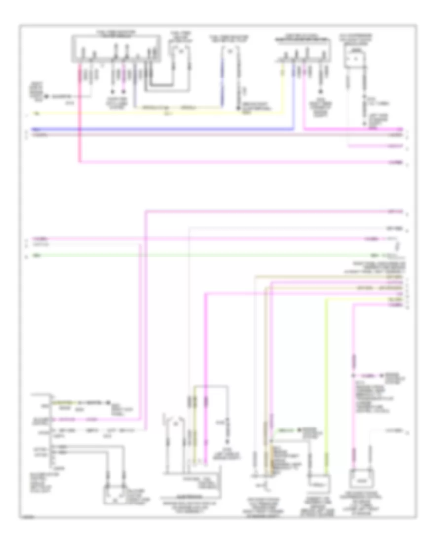
Automatic A/C Wiring Diagram (2 of 3) for Ford Transit Connect XL 2014
List of elements for Automatic A/C Wiring Diagram (2 of 3) for Ford Transit Connect XL 2014:
- (a/c compressor)
- (behind right quarterpanel) g303
- (center of dash) electric booster heater
- (left side of engine compt) g103
- (right side of engine compt) g109
- Air conditioning (a/c) clutch
- Air conditioning (a/c) pressure transducer (right front corner of engine compt)
- Air conditioning compressor control solenoid (1.6l turbo) (lower left front of engine)
- Ambient air temperature sensor (behind left side of front bumper)
- Blower control
- Blower motor (right side of dash)
- Blower motor control module (bottom of hvac unit)
- C211
- C212
- C2603a
- C2603b
- C2603c
- C297a
- C297b
- C327
- Cbp18
- Chf01
- Computer data lines system
- Electronics
- Engine controls system
- Engine cooling fan module (on engine cooling fan assembly)
- Fan control variable
- Fuel fired booster heater fuel pump
- Fuel fired booster heater module
- Fuel fired heater water pump
- G106 (left side of engine compt)
- G108 (right rear corner of engine compt)
- G203 (right kick panel)
- Gd130
- Gd132
- Gd339
- Gnd
- Ign
- Motor +
- Motor -
- Ms can+
- Ms can-
- Nca
- Pmw
- Pump+
- Pump-
- Pwr
- Right panel discharge air temperature sensor (in right panel vent assembly)
- S102 (1.6l turbo)
- S114 (engine wiring harness, near breakout to transmission fluid warmer temperature control valve 2)
- S126
- S143
- S238
- Sbb05
- Sbb24
- Vdb06
- Vdb07
- Ve203
- Vh101
- Vpwr
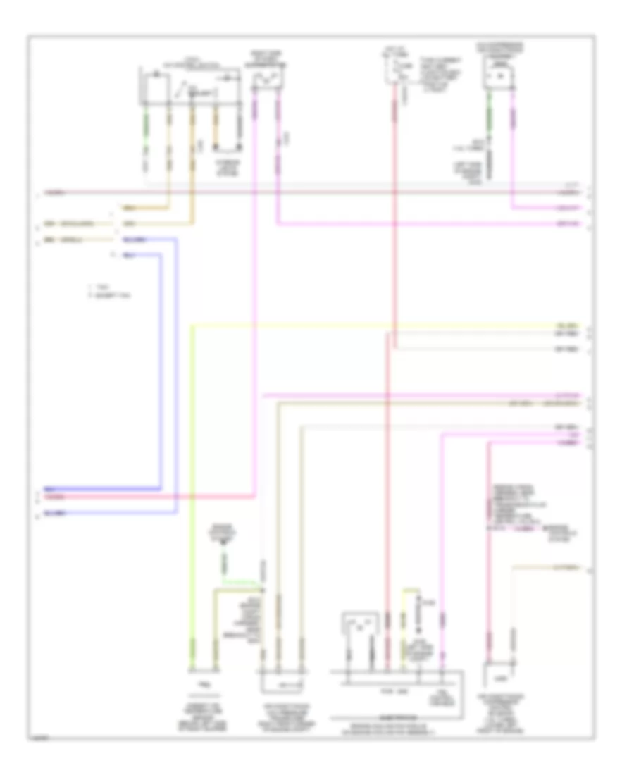
Automatic A/C Wiring Diagram (3 of 3) for Ford Transit Connect XL 2014
List of elements for Automatic A/C Wiring Diagram (3 of 3) for Ford Transit Connect XL 2014:
- (engine wiring harness, near breakout to camshaft position 11 sensor) (1.6l turbo) s107
- (engine wiring harness, near breakout to electronic throttle control) (except 1.6l turbo) s120
- (left side of engine compt) g106
- (or lh108)
- (or rh107)
- (or vdn06)
- (or vh407)
- 1.6l turbo
- Aat
- Accr
- Acps
- Active grille shutter (behind left end of front grille)
- Air conditioning (a/c) clutch relay
- Battery junction box (bjb) (left rear corner of engine compt)
- Blower motor relay
- C1035c
- C1617e
- C1617h
- C175b
- C175e
- C1915b
- C1915e
- Ch109
- Cht
- Computer data lines system
- Cylinder head temperature (cht) sensor (except 1.6l turbo) (top center of cylinder head)
- Engine controls system
- Engine coolant temperature (ect) sensor (1.6l turbo) (right rear of cylinder head)
- Engine cooling fan relay
- Evdc
- Except 1.6l turbo
- Fcv
- Fuse 10a
- Fuse 15a
- Fuse 25a
- Fuse 40a
- Fuse 5 80a
- Fuse 5a
- Fuse 8 50a
- G106 (left side of engine compt)
- Gnd
- High current battery junction box (on battery positive (+) post)
- Hot at all times
- Hot w/ powertrain control module (pcm) relay energized
- Hs can+
- Hs can-
- Lin
- Powertrain control module (pcm) (left front of engine compt)
- Re329
- Re405
- Re407
- Red
- S109 (1.6l turbo) (engine wiring harness, in breakout to pcm)
- S122 (except 1.6l turbo) (engine wiring harness, near breakout to electronic throttle control)
- S127
- S131
- S132
- Sig rtn
- Sigrtn
- Vdb04
- Vdb05
- Vdc46
- Ve203
- Ve462
- Ve712
- Ve716
- Ve750
- Vh442
- Vh443
- Vpwr
- Vref
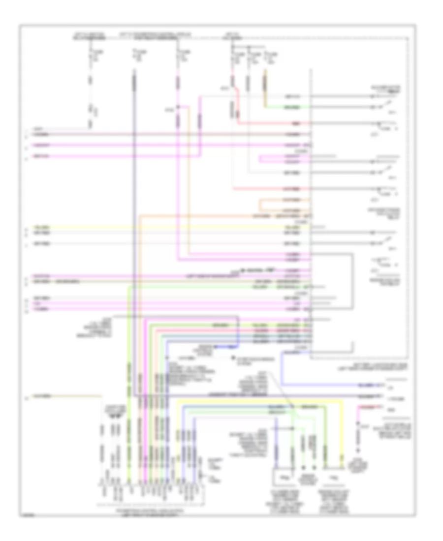
Manual A/C Wiring Diagram (1 of 3) for Ford Transit Connect XL 2014
List of elements for Manual A/C Wiring Diagram (1 of 3) for Ford Transit Connect XL 2014:
- (left kick panel) g202
- (or ch434)
- (or cln17)
- A/c on
- A/c on sw
- A/c request
- Air distribution door actuator (upper left side of hvac unit)
- Air inlet mode door actuator (upper left side of hvac blower housing)
- Aux htr req
- Aux htr sw
- Auxiliary junction box (ajb) (behind right quarterpanel)
- Blower motor resistor (near blower motor)
- Blower speed 1
- Blower speed 2
- Blower speed 3
- Blower speed 4
- Bmrc
- Body control module (bottom right center of dash)
- C2280a
- C2280c
- C2280f
- C2357a
- C2357b
- C311
- Cbp04
- Ch123
- Ch201
- Ch202
- Ch203
- Ch204
- Ch205
- Ch207
- Ch208
- Ch232
- Ch233
- Ch234
- Ch235
- Ch236
- Ch427
- Ch428
- Ch429
- Ch430
- Ch434
- Chp03
- Cln17
- Computer data lines system
- Evap temp sens
- Evaporator discharge air temperature sensor
- Except taxi
- Fuse 10a
- Fuse 7.5a
- G203 (right kick panel)
- Gd338
- Gd339
- Gnd
- Heating, ventilation & air conditioning (hvac) module
- Hot at all times
- Hot w/ ignition relay energized
- Hs can+
- Hs can-
- Ign
- Illum
- Interior lights system
- Micro
- Mode door a
- Mode door b
- Mode door c
- Mode door d
- Mode door power
- Ms can +
- Ms can-
- Rear acon
- Recirc door a
- Recirc door b
- Rh105
- S224 (instrument panel wiring harness, near breakout to sasm)
- S238
- S240
- S241
- Sbp27
- Sigrtn
- Taxi
- Temp door a
- Temp door b
- Temp door c
- Temp door d
- Temp door power
- Temperature door actuator (left side of hvac unit)
- Thermal limiter
- V batt
- Vdb04
- Vdb05
- Vdb06
- Vdb07
- Vh406
- W/ start/stop system
- W/o start/stop system
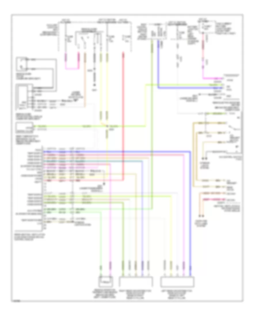
Manual A/C Wiring Diagram (2 of 3) for Ford Transit Connect XL 2014
List of elements for Manual A/C Wiring Diagram (2 of 3) for Ford Transit Connect XL 2014:
- (a/c compressor) air conditioning clutch
- (engine wiring harness, near breakout to transmission fluid warmer temperature control valve 2) s114
- (left side of engine compt) g103
- (right side of dash) blower motor
- (taxi) a/c control switch
- A/c request
- Air conditioning (a/c) pressure transducer (right front corner of engine compt)
- Air conditioning compressor control solenoid (1.6l turbo) (lower left front of engine)
- Ambient air temperature sensor (behind left side of front bumper)
- C1617h
- C212
- C315
- Electronics
- Engine controls system
- Engine cooling fan module (on engine cooling fan assembly)
- Except taxi
- Fan control variable
- Fuse 50a
- G106 (left side of engine compt)
- Gd130
- Gnd
- High current battery junction box (on battery positive (+) post)
- Hot at all times
- Interior lights system
- Nca
- Pwr
- S102 (1.6l turbo)
- S126
- S212 (engine compt wiring harness, near breakout to bcm)
- Sbb05
- Taxi
- Ve203
Manual A/C Wiring Diagram (3 of 3) for Ford Transit Connect XL 2014
List of elements for Manual A/C Wiring Diagram (3 of 3) for Ford Transit Connect XL 2014:
- (engine wiring harness, near breakout to camshaft position 11 sensor)
- (or ch302)
- (or lh108)
- (or re407)
- (or vdn06)
- (or vh407)
- 1.6l turbo
- Aat
- Accr
- Acps
- Active grille shutter actuator (behind left end of front grille)
- Air conditioning (a/c) clutch relay
- Battery junction box (bjb) (left rear corner of engine compt)
- Blower motor relay
- C1035c
- C175b
- C175e
- C1915b
- C1915e
- C212
- Ch109
- Cht
- Computer data lines system
- Cylinder head temperature (cht) sensor (except 1.6l turbo) (top center of cylinder head)
- Ect
- Engine controls system
- Engine coolant temperature (ect) sensor (1.6l turbo) (right rear of cylinder head)
- Engine cooling fan relay
- Evdc
- Except 1.6l turbo
- Fcv
- Fuse 10a
- Fuse 15a
- Fuse 40a
- Fuse 5a
- G106 (left side of engine compt)
- Gnd
- Hot at all times
- Hot w/ ignition relay energized
- Hot w/ powertrain control module (pcm) relay energized
- Hs can+
- Hs can-
- Lin
- Powertrain control module (pcm) (left front of engine compt)
- Re329
- Re405
- Red
- Rh107
- S107 (1.6l turbo)
- S109 (1.6l turbo) (engine wiring harness, in breakout to pcm)
- S120 (except 1.6l turbo) (engine wiring harness, near breakout to electronic throttle control)
- S122 (except 1.6l turbo) (engine wiring harness, near breakout to electronic throttle control)
- S127
- S131
- S132
- Sig rtn
- Starting/charging system
- V power
- Vdb04
- Vdb05
- Vdc46
- Ve203
- Ve462
- Ve712
- Ve716
- Ve750
- Vh442
- Vh443
- Vref
Rear Auxiliary A/C Wiring Diagram for Ford Transit Connect XL 2014
List of elements for Rear Auxiliary A/C Wiring Diagram for Ford Transit Connect XL 2014:
- (under driver's scuff plate) g300
- A/c control switch (taxi)
- A/c request
- A/c request switch
- Aux htr req
- Aux rear
- Auxiliary junction box (behind right quarterpanel)
- Batt+
- Battery junction box (left rear corner of engine compt)
- Body control module (bottom right center of dash)
- C1617g
- C212
- C213
- C2280b
- C2357a
- C315
- C316
- C3443a
- C3443b
- C3443c
- C3448a
- C3448c
- Cbp18
- Cbp40
- Ch201
- Ch202
- Ch203
- Ch204
- Ch205
- Ch232
- Ch233
- Ch234
- Ch235
- Ch236
- Ch434
- Chp03
- Cln17
- Computer data lines system
- Ctrl
- Evaporator sens
- Evaporator sens gnd
- Expan valve
- Fuse 10a
- Fuse 40a
- Fuse 5a
- Fuse 7 80a
- Fuse 7.5a
- G201 (under passenger's door sill)
- G302 (under driver's door sill)
- G401
- Gd311
- Gd354
- Gnd
- Heater rear ptc
- Heating, ventilation & air conditioning (hvac) module
- High current battery junction box (on battery positive (+) post)
- Hot at all times
- Hot w/ ignition relay energized
- Ign
- Illm
- Interior lights system
- Left rear air distribution door actuator (base of left rear "c" pillar)
- Micro
- Mode door a
- Mode door b
- Mode door c
- Mode door d
- Mode door power
- Ms can+
- Ms can-
- Nca
- Pwm
- Pwm 1
- Pwm1
- Rear a/c on
- Rear blower motor (under driver's seat)
- Rear blower motor control module (under driver's seat)
- Rear blower motor relay
- Rear electric booster heater (behind driver's seat, under floor)
- Rear evaporator temperature sensor (behind driver's seat, under floor)
- Rear heating, ventilation & air conditioning (rhvac) control module
- Rear thermostatic expansion valve (behind driver's seat, under floor)
- Red
- Rh105
- Rha29
- Right rear air distribution door actuator (base of right rear "c" pillar)
- S205
- S324
- S330
- S402
- Sbp17
- Temp door a
- Temp door b
- Temp door c
- Temp door d
- Temp door power
- Txv out ctrl
- Vbatt
- Vdb06
- Vdb07
- Vh101
- Vh406
- Vpwr
Semi Automatic A/C Wiring Diagram (1 of 3) for Ford Transit Connect XL 2014
List of elements for Semi Automatic A/C Wiring Diagram (1 of 3) for Ford Transit Connect XL 2014:
- Ac on
- Ac on sw
- Air distribution door actuator (lower left side of hvac unit)
- Aux htr req
- Aux htr sw
- Auxiliary junction box (ajb) (behind right quarterpanel)
- Blower motor resistor (near blower motor)
- Blower speed 1
- Blower speed 2
- Blower speed 3
- Blower speed 4
- Bmrc
- Body control module (bottom right center of dash)
- C2280a
- C2280c
- C2280f
- C2357a
- C2357b
- C311
- C316
- Ch123
- Ch201
- Ch202
- Ch203
- Ch204
- Ch205
- Ch206
- Ch207
- Ch208
- Ch209
- Ch210
- Ch232
- Ch233
- Ch234
- Ch235
- Ch236
- Ch427
- Ch428
- Ch429
- Ch430
- Ch434
- Chp03
- Computer data lines system
- Evap temp sens
- Evaporator discharge air temperature sensor
- Fuse 10a
- G202 (left kick panel)
- G203 (right kick panel)
- Gd338
- Gd339
- Gnd
- Heating, ventilation & air conditioning (hvac) module
- Hot at all times
- Hs can+
- Hs can-
- Micro
- Mode door a
- Mode door b
- Mode door c
- Mode door d
- Mode door power
- Ms can +
- Ms can -
- Recirc a
- Recirc b
- Recirc c
- Recirc d
- Recirc power
- Recirculation air inlet door actuator
- Rh105
- S224 (instrument panel wiring harness, near breakout to sasm)
- S238
- S250
- Sbp27
- Sigrtn
- Temp door a
- Temp door b
- Temp door c
- Temp door d
- Temp door power
- Temperature door actuator (left side of hvac unit)
- Thermal limiter
- V batt
- Vdb04
- Vdb05
- Vdb06
- Vdb07
- Vh406
- W/ start/stop system
- W/o start/stop system
Semi Automatic A/C Wiring Diagram (2 of 3) for Ford Transit Connect XL 2014
List of elements for Semi Automatic A/C Wiring Diagram (2 of 3) for Ford Transit Connect XL 2014:
- (a/c compressor) air conditioning (a/c) clutch
- (engine wiring harness, near breakout to transmission fluid warmer temperature control valve 2) s114
- (left side of engine compt) g103
- (right side of dash) blower motor
- Air conditioning (a/c) pressure transducer (right front corner of engine compt)
- Air conditioning compressor control solenoid (1.6l turbo) (lower left front of engine)
- Ambient air temperature sensor (behind left side of front bumper)
- C1617h
- C212
- Electronics
- Engine controls system
- Engine cooling fan module (on engine cooling fan assembly)
- Fan control variable
- Fuse 50a
- G106 (left side of engine compt)
- Gd130
- Gnd
- High current battery junction box (on battery positive (+) post)
- Hot at all times
- Nca
- Pwr
- S102 (1.6l turbo)
- S126
- S212 (engine compt wiring harness, near breakout to bcm)
- Sbb05
- Ve203
Semi Automatic A/C Wiring Diagram (3 of 3) for Ford Transit Connect XL 2014
List of elements for Semi Automatic A/C Wiring Diagram (3 of 3) for Ford Transit Connect XL 2014:
- (engine wiring harness, near breakout to camshaft position 11 sensor)
- (or ch302)
- (or lh108)
- (or re407)
- (or vdn06)
- 1.6l turbo
- Aat
- Accr
- Acps
- Active grille shutter actuator (behind left end of front grille)
- Air conditioning (a/c) clutch relay
- Battery junction box (bjb) (left rear corner of engine compt)
- Blower motor relay
- C1035c
- C175b
- C175e
- C1915b
- C1915e
- Ch109
- Cht
- Computer data lines system
- Cylinder head temperature (cht) sensor (except 1.6l turbo) (top center of cylinder head)
- Ect
- Engine controls system
- Engine coolant temperature (ect) sensor (1.6l turbo) (right rear of cylinder head)
- Engine cooling fan relay
- Evdc
- Except 1.6l turbo
- Fcv
- Fuse 10a
- Fuse 15a
- Fuse 40a
- Fuse 5a
- G106 (left side of engine compt)
- Gnd
- Hot at all times
- Hot w/ powertrain control module (pcm) relay energized
- Hs can+
- Hs can-
- Lin
- Powertrain control module (pcm) (left front of engine compt)
- Re329
- Re405
- Red
- Rh107
- S107 (1.6l turbo)
- S109 (1.6l turbo) (engine wiring harness, in breakout to pcm)
- S120 (except 1.6l turbo) (engine wiring harness, near breakout to electronic throttle control)
- S122 (except 1.6l turbo) (engine wiring harness, near breakout to electronic throttle control)
- S127
- S131
- S132
- Sig rtn
- Sigrtn
- Starting/charging system
- V power
- Vdb04
- Vdb05
- Vdc46
- Ve203
- Ve462
- Ve712
- Ve716
- Ve750 (or vh407)
- Vh442
- Vh443
- Vref

 Čeština
 Dansk
Dansk Deutsch
 Ελληνικά
 English
 Español
 Suomi
Suomi Français
 Français
 עברית
עברית Hrvatski
 Magyar
 Italiano
 日本語
日本語 한국어
한국어 Nederlands
 Polski
 Português
 Português
 Română
 Русский
 Slovenčina
 Slovenščina
 Svenska
 Türkçe
 中文 (中国)