AIR CONDITIONING
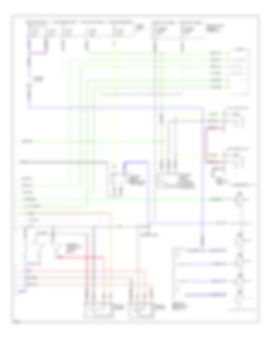
Air Conditioning Wiring Diagrams, A/T (1 of 2) for Infiniti G20 1993
 https://portal-diagnostov.com/license.html
Automotive Electricians Portal FZCO
Automotive Electricians Portal FZCO
https://portal-diagnostov.com/license.html
https://portal-diagnostov.com/license.html
Automotive Electricians Portal FZCO
Automotive Electricians Portal FZCO
List of elements for Air Conditioning Wiring Diagrams, A/T (1 of 2) for Infiniti G20 1993:
- (attached to front of heater unit)
- (in relay box 2)
- (left front of engine comp., on receiver-drier)
- (left kick panel)
- (near battery)
- A/c comp- ressor clutch
- A/c relay (in relay box 1)
- Acrly
- Arcon
- B/l
- Def
- Eccs control unit (behind center console)
- Except 1996
- F.i.c.d. solenoid valve
- F/d
- Foot
- G101
- G200
- Heater & a/c selector switch
- Intake door motor
- Interior lights system
- Mode door motor
- Nca
- Pdsw
- Push control module
- Radiator fan relay #1 (in relay box 1)
- Radiator fan relay #2
- Red
- Rfrl
- Rfrn
- Thermal protector
- Thermistor
- Thermo control amp (behind center of i/p)
- Triple pressure switch
- Usa only
- Vent
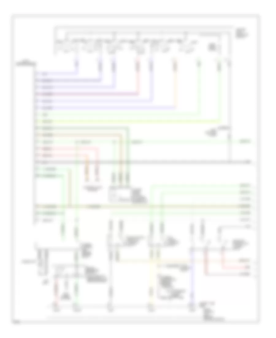
Air Conditioning Wiring Diagrams, A/T (2 of 2) for Infiniti G20 1993
List of elements for Air Conditioning Wiring Diagrams, A/T (2 of 2) for Infiniti G20 1993:
- (attached to front of heater unit)
- (behind right side of i/p)
- (in relay box 1)
- (near battery)
- Blower motor
- Blower relay (behind left kick panel)
- Fan switch
- Full cold switch
- Fuse & fusible link box: underhood
- Fuse 10a
- Fuse 15a
- Fuse block: i/p
- Fusible link b 30a
- Fusible link c 30a
- G101
- G200 (left kick panel)
- Hot at all times
- Hot in accy or on
- Hot in on or start
- J/c #4
- Max cold door motor
- Off
- Rad fan motor #1
- Rad fan motor #2
- Radiator fan relay #3
- Red
- Resistor
- Vent mode switch
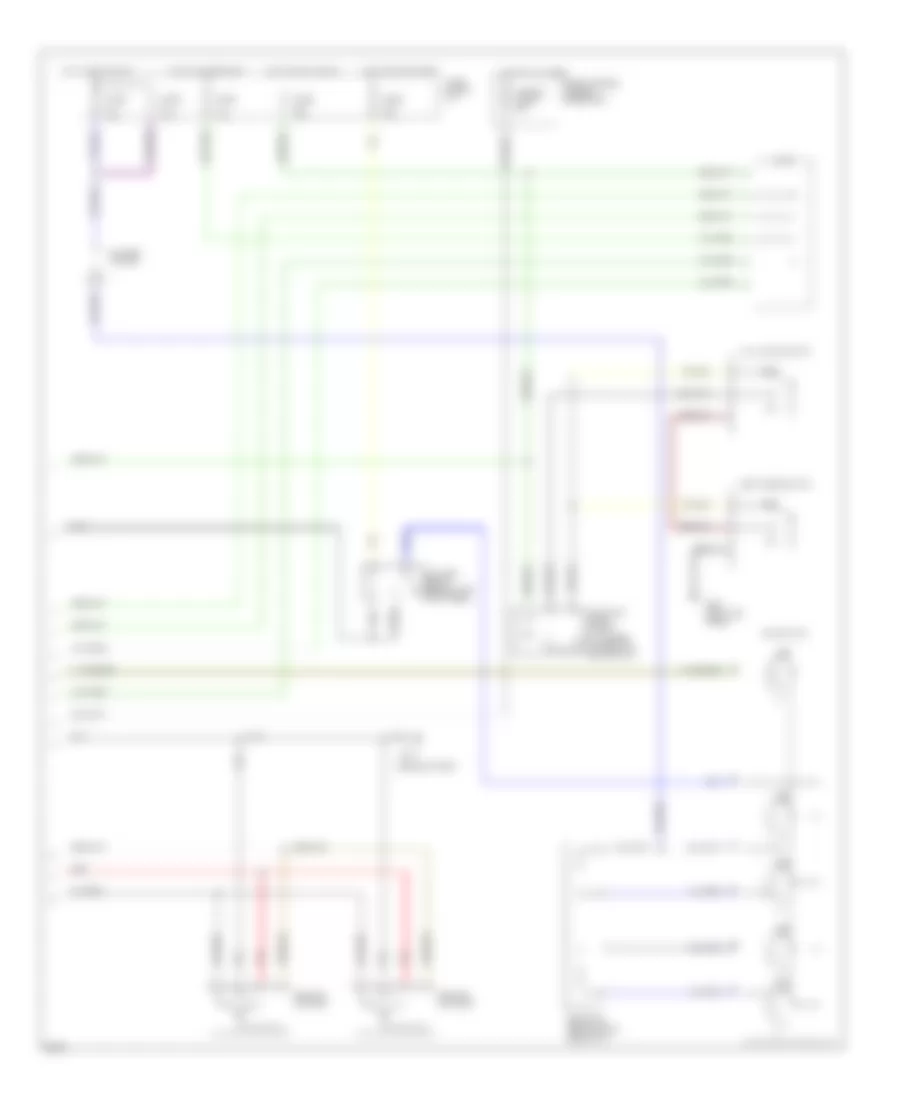
Air Conditioning Wiring Diagrams, M/T (1 of 2) for Infiniti G20 1993
List of elements for Air Conditioning Wiring Diagrams, M/T (1 of 2) for Infiniti G20 1993:
- (attached to front of heater unit)
- (in relay box 2)
- (left front of engine comp., on receiver-drier)
- (left kick panel)
- (near battery)
- A/c compressor clutch
- A/c relay (in relay box 1)
- Acrly
- Arcon
- B/l
- Def
- Eccs control unit (behind center console)
- Except 1996
- F.i.c.d. solenoid valve
- F/d
- Foot
- G101
- G200
- Heater & a/c selector switch
- Intake door motor
- Interior lights system
- Mode door motor
- Nca
- Pdsw
- Push control module
- Radiator fan relay #1 (in relay box 1)
- Radiator fan relay #2
- Red
- Rfrh
- Rfrl
- Thermal protector (behind center of grille)
- Thermistor
- Thermo control amp (behind center of i/p)
- Triple pressure switch
- Usa only
- Vent
Air Conditioning Wiring Diagrams, M/T (2 of 2) for Infiniti G20 1993
List of elements for Air Conditioning Wiring Diagrams, M/T (2 of 2) for Infiniti G20 1993:
- (attached to front of heater unit)
- (behind right side of i/p)
- (near battery)
- Blower motor
- Blower relay (behind left kick panel)
- Fan switch
- Full cold switch
- Fuse & fusible link box: underhood
- Fuse 10a
- Fuse 15a
- Fuse block: i/p
- Fusible link b 30a
- G101
- G200 (left kick panel)
- Hot at all times
- Hot in accy or on
- Hot in on or start
- J/c #4
- Max cold door motor
- Off
- Rad fan motor #1
- Rad fan motor #2
- Red
- Resistor
- Vent mode switch

 Čeština
 Dansk
Dansk Deutsch
 Ελληνικά
 English
 Español
 Suomi
Suomi Français
 Français
 עברית
עברית Hrvatski
 Magyar
 Italiano
 日本語
日本語 한국어
한국어 Nederlands
 Polski
 Português
 Português
 Română
 Русский
 Slovenčina
 Slovenščina
 Svenska
 Türkçe
 中文 (中国)