AIR CONDITIONING
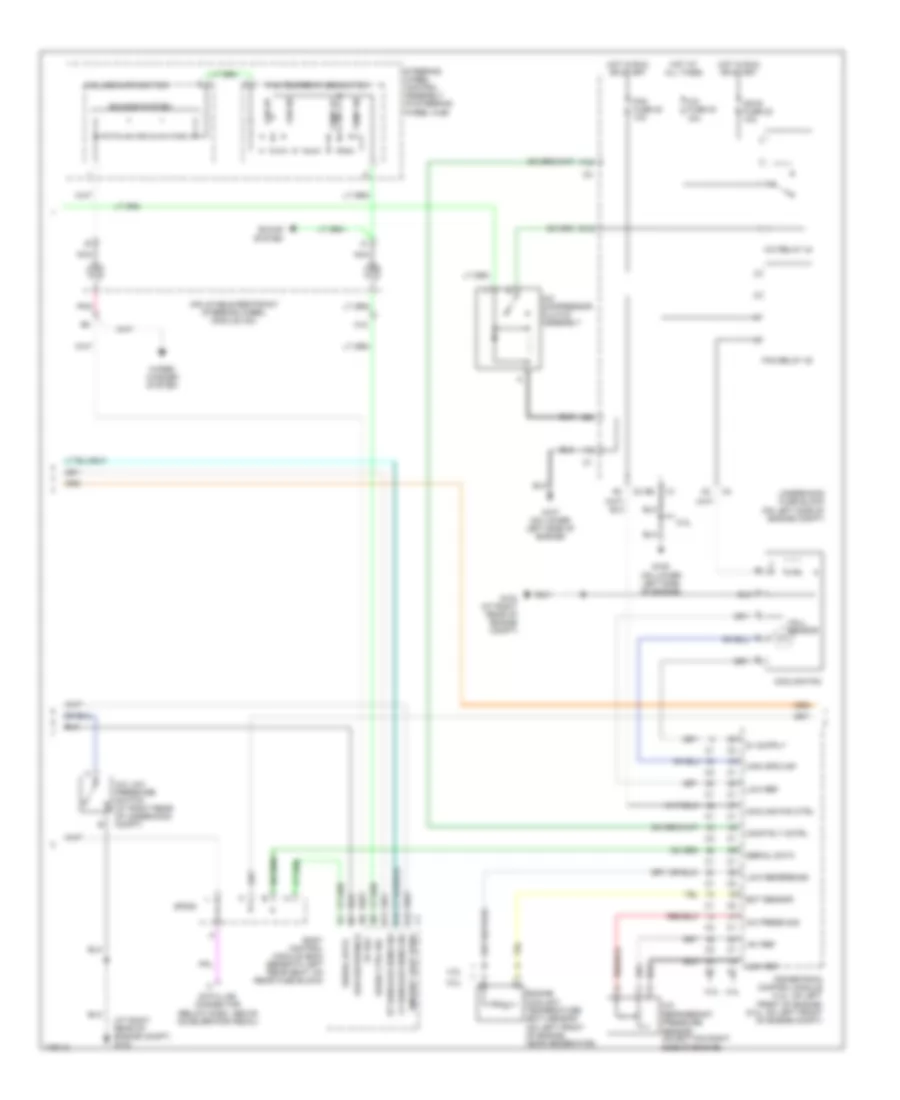
Automatic A/C Wiring Diagram (1 of 3) for Isuzu Ascender 2003
 https://portal-diagnostov.com/license.html
Automotive Electricians Portal FZCO
Automotive Electricians Portal FZCO
https://portal-diagnostov.com/license.html
https://portal-diagnostov.com/license.html
Automotive Electricians Portal FZCO
Automotive Electricians Portal FZCO
List of elements for Automatic A/C Wiring Diagram (1 of 3) for Isuzu Ascender 2003:
- (in dash center trim panel, beneath radio) hvac control module
- 5v ref
- A/c comp status
- A/c low press sw
- A10
- A11
- A12
- Air temp door ctrl
- Air temp dr pos sig
- Air temperature actuator (left) (behind left center of dash)
- Air temperature actuator (right) (behind right center of dash)
- Ambient air temp sig
- Ambient air temperature sensor
- Ambient light
- Ambient light/ sunload sensor assembly (in center of upper dash trim panel)
- B10
- B11
- B12
- Battery
- Blower fuse 35 40a
- Blower motor
- Blower motor control module (below right side of dash)
- Blwr mtr spd ctrl
- Class 2
- Control
- Coolant bypass ctrl
- Coolant bypass valve
- Def door pos sig
- Defrost actuator (behind upper left center of dash)
- Defrost door ctrl
- G102 (at left side of engine compartment)
- G103 (at right rear of engine compt)
- G201 (near right front of lower console)
- G302 (on lower left ``b" pillar)
- Ground
- Hot at all times
- Hot in run
- Hvac 1 fuse 39 10a
- Hvac b fuse 36 10a
- Ign 3
- Inside air temp ctrl
- Inside air temp sig
- Inside air temperature sensor (in left ``b" pillar)
- Left sensor
- Low ref
- Low reference
- Lower left air temperature sensor (in lower left air duct assembly)
- Lower right air temperature sensor (in lower right air duct assembly)
- Lwr lt air temp sig
- Lwr rt air temp sig
- Mode actuator (behind upper left center of dash)
- Mode door ctrl
- Mode door pos sig
- Nca
- Rear fuse block (below left rear seat)
- Recirc door cntrl
- Recirc dr pos sig
- Recirculation actuator (above blower motor, on right side of dash carrier)
- Red
- Right sensor
- Solid state
- Sp201
- Tan
- Underhood fuse block (on left side of engine compt)
- Upper left air temperature sensor (in upper air duct)
- Upper right air temperature sensor (in upper air duct)
- Uppr lt air temp sig
- Uppr rt air temp sig
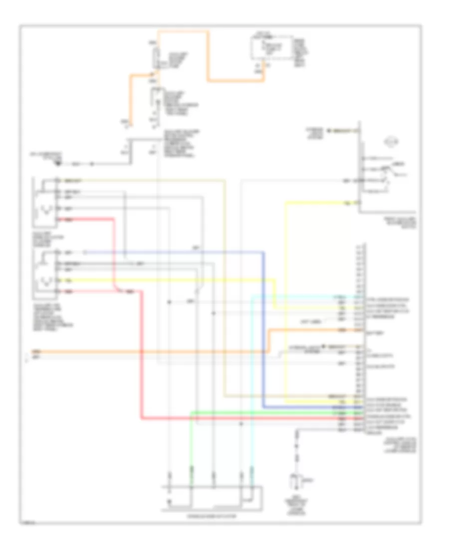
Automatic A/C Wiring Diagram (2 of 3) for Isuzu Ascender 2003
List of elements for Automatic A/C Wiring Diagram (2 of 3) for Isuzu Ascender 2003:
- (at right rear of engine compt) g103
- +5v ref
- 4.2l
- 5.3l
- 5.3l 4.2l
- 5v ref
- A/c compressor clutch assembly
- A/c fuse 30 10a
- A/c low pressure switch (at right rear of underhood compt)
- A/c press sig
- A/c refrigerant pressure sensor (on bottom right side of engine)
- A/c relay 44
- A12
- Ambient light sens
- B11
- B12
- Body control module (bcm) (beneath left rear seat, on rear fuse block)
- Comp rly cntrl
- Cooling fan
- Cooling fan ctrl
- Data link connector (below dash, above accelerator pedal)
- E12
- Ect sensor
- Engine coolant temperature (ect) sensor (on left front of engine, near generator)
- F12
- Fan dn
- Fan fuse 20 10a
- Fan relay 45
- Fan up
- Fan/temperature switch
- G103 (at right rear of engine compt)
- G107 (on lower left side of engine)
- G108 (on lower left side of engine)
- Hall sensor
- High spd maf
- Hot at all times
- Hot in run or start
- Ign e fuse 22 10a
- Inflatable restraint steering wheel module coil
- Low ref
- Low reference
- Lt sunload sens sig
- Nca
- Pnk
- Powertrain control module (4.2l: on left front of engine) (5.3l: on left front of engine compt)
- Radio ctrl sig
- Rt sunload sens sig
- Serial data
- Sound system
- Sounds system
- Sp205
- Steering wheel control assembly (in steering wheel hub)
- Temp dn
- Temp up
- Underhood fuse block (on left side of engine compt)
- Volume/am/fm switch
- Wiper/ washer system
Automatic A/C Wiring Diagram (3 of 3) for Isuzu Ascender 2003
List of elements for Automatic A/C Wiring Diagram (3 of 3) for Isuzu Ascender 2003:
- (not used)
- (on lower right "d" pillar) g402
- 30a
- 5v reference
- A10
- A11
- A12
- A13
- A14
- A15
- A16
- Auc hvac enable
- Aux act door ctlr
- Aux air temp dr ctlr
- Aux air temp dr pos
- Aux blwr mtr
- Aux mode door ctrl
- Aux mode dr pos sig
- Auxiliary air temperature actuator (on rear hvac module, behind right rear interior body panel)
- Auxiliary blower motor (behind interior right rear trim panel)
- Auxiliary blower motor control processor (in rear hvac module, behind right rear interior panel)
- Auxiliary blower motor fuse
- Auxiliary hvac control module (at rear of lower console)
- Auxiliary mode actuator (in lower console)
- B10
- B11
- B12
- B13
- B14
- B15
- B16
- Battery
- Class 2 data
- Console mode actuator
- Console mode dr ctrl
- Ctrl mode dr pos sig
- Front auxiliary blower motor switch
- G201 (near right front of lower console)
- Ground
- Hot at all times
- Ill
- Interior lights system
- Low reference
- Off
- Rear
- Rear fuse block (below left rear seat)
- Red
- Rr hvac fuse 13 30a
- Sp201
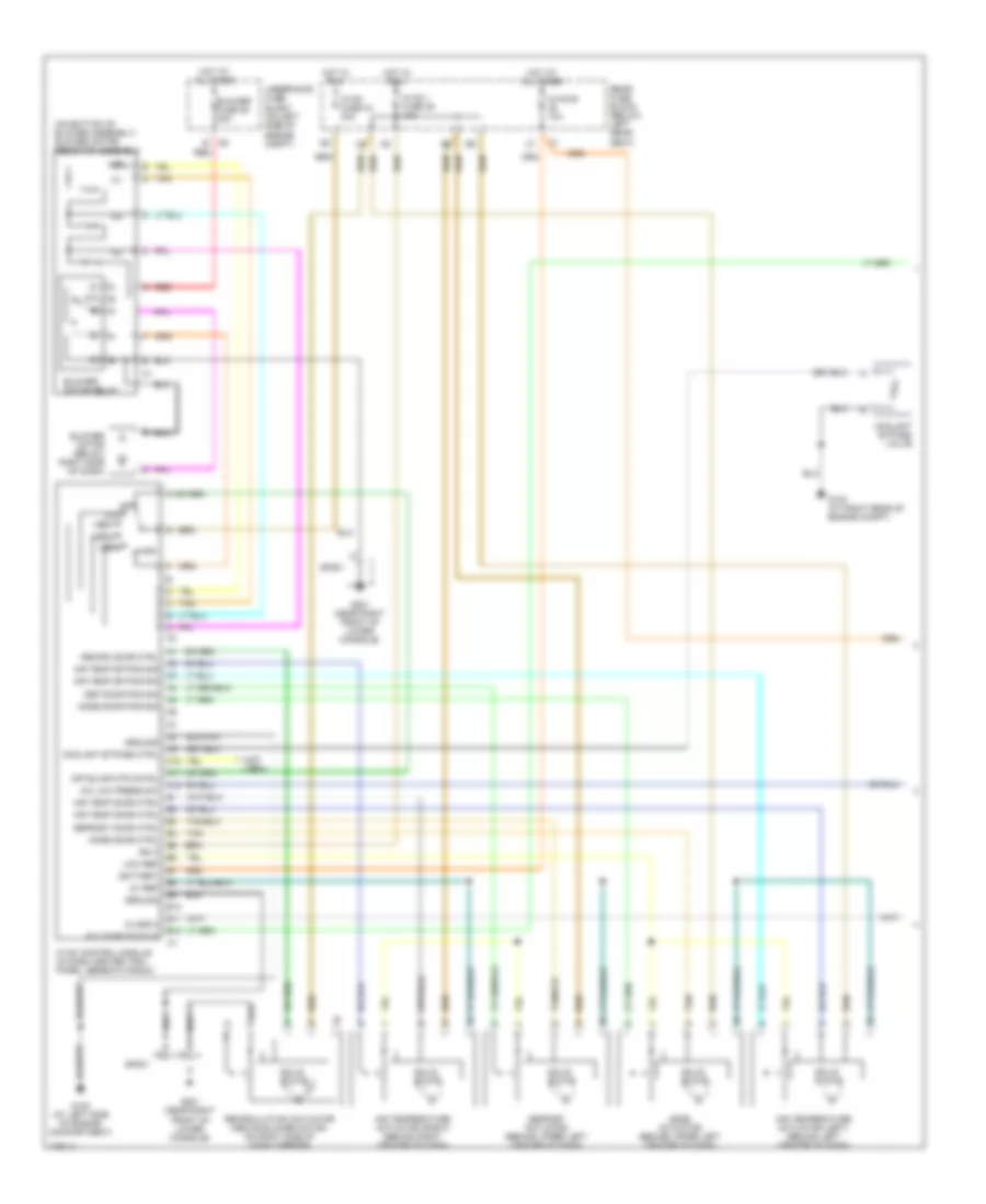
Manual A/C Wiring Diagram (1 of 3) for Isuzu Ascender 2003
List of elements for Manual A/C Wiring Diagram (1 of 3) for Isuzu Ascender 2003:
- (not used)
- (on bottom of blower assembly) blower motor resistor assembly
- 5v ref
- 87a
- A/c comp status
- A/c low press sw
- A10
- A11
- A12
- Air temp door ctrl
- Air temp dr pos sig
- Air temperature actuator (left) (behind left center of dash)
- Air temperature actuator (right) (behind right center of dash)
- B10
- B11
- B12
- Battery
- Blower fuse 35 40a
- Blower motor (below right side of dash)
- Blower motor relay
- Class 2
- Coolant bypass ctrl
- Coolant bypass valve
- Def door pos sig
- Defrost actuator (behind upper left center of dash)
- Defrost door ctrl
- G102 (at left side of engine compartment)
- G103 (at right rear of engine compt)
- G201 (near right front of lower console)
- Ground
- High
- Hot at all times
- Hot in run
- Hvac control module (in dash center trim panel, beneath radio)
- Hvac fuse 44 30a
- Hvac i fuse 39 10a
- Hvac-b 10a
- Ign 3
- Low
- Low ref
- Med1
- Med2
- Med3
- Mode actuator (behind upper left center of dash)
- Mode door ctrl
- Mode door pos sig
- Off
- Off blwr mtr cntrl
- Rear fuse block (below left rear seat)
- Recirc door ctrl
- Recirculation actuator (above blower motor, on right side of dash carrier)
- Red
- Solid state
- Sp201
- Tan
- Underhood fuse block (on left side of engine compt)
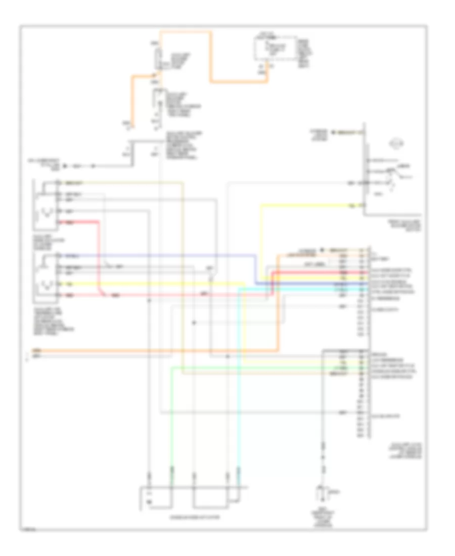
Manual A/C Wiring Diagram (2 of 3) for Isuzu Ascender 2003
List of elements for Manual A/C Wiring Diagram (2 of 3) for Isuzu Ascender 2003:
- (at right rear of engine compt) g103
- +5v ref
- 4.2l
- 5.3l
- 5.3l 4.2l
- A/c compressor clutch assembly
- A/c compressor clutch relay
- A/c fuse 30 10a
- A/c low pressure switch (at right rear of underhood compt)
- A/c press sig
- A/c refrigerant pressure sensor (on bottom right side of engine)
- Comp rly cntrl
- Cooling fan
- Cooling fan ctrl
- Data link connector (below dash, above accelerator pedal)
- E12
- Ect sensor
- Engine coolant temperature (ect) sensor (on left front of engine, near generator)
- F12
- Fan fuse 20 10a
- Fan relay 45
- G103 (at right rear of engine compt)
- G107 (on lower left side of engine)
- G108 (on lower left side of engine)
- Hall sensor
- High spd maf
- Hot at all times
- Hot in run or start
- Ign e fuse 22 10a
- Low ref
- Low reference
- Powertrain control module (4.2l: on left front of engine) (5.3l: on left front of engine compt)
- Serial data
- Sp205
- Underhood fuse block (on left side of engine compt)
Manual A/C Wiring Diagram (3 of 3) for Isuzu Ascender 2003
List of elements for Manual A/C Wiring Diagram (3 of 3) for Isuzu Ascender 2003:
- (not used)
- (on lower right ``d" pillar) g402
- 30a
- 5v reference
- A10
- A11
- A12
- A13
- A14
- A15
- A16
- Auc hvac enable
- Aux act door ctlr
- Aux air temp dr ctlr
- Aux air temp dr pos
- Aux blwr mtr
- Aux mode door ctrl
- Aux mode dr pos sig
- Auxiliary air temperature actuator (on rear hvac module, behind right rear interior body panel)
- Auxiliary blower motor (behind interior right rear trim panel)
- Auxiliary blower motor control processor (in rear hvac module, behind right rear interior panel)
- Auxiliary blower motor fuse
- Auxiliary hvac control module (at rear of lower console)
- Auxiliary mode actuator (in lower console)
- B10
- B11
- B12
- B13
- B14
- B15
- B16
- Battery
- Class 2 data
- Console mode actuator
- Console mode dr ctrl
- Ctrl mode dr pos sig
- Front auxiliary blower motor switch
- G201 (near right front of lower console)
- Ground
- Hot at all times
- Ill
- Interior lights system
- Low reference
- Off
- Rear
- Rear fuse block (below left rear seat)
- Red
- Rr hvac fuse 13 30a
- Sp201

 Čeština
 Dansk
Dansk Deutsch
 Ελληνικά
 English
 Español
 Suomi
Suomi Français
 Français
 עברית
עברית Hrvatski
 Magyar
 Italiano
 日本語
日本語 한국어
한국어 Nederlands
 Polski
 Português
 Português
 Română
 Русский
 Slovenčina
 Slovenščina
 Svenska
 Türkçe
 中文 (中国)