AIR CONDITIONING
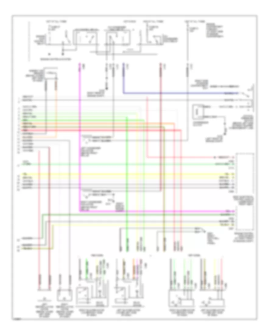
Air Conditioning Wiring Diagrams (1 of 2) for Land Rover Range Rover HSE 1998
 https://portal-diagnostov.com/license.html
Automotive Electricians Portal FZCO
Automotive Electricians Portal FZCO
https://portal-diagnostov.com/license.html
https://portal-diagnostov.com/license.html
Automotive Electricians Portal FZCO
Automotive Electricians Portal FZCO
List of elements for Air Conditioning Wiring Diagrams (1 of 2) for Land Rover Range Rover HSE 1998:
- (on top center of dash) sun sensor
- A/c aspirator (behind center of dash)
- Auxiliary power 1 relay
- Auxiliary power 2 relay
- Body electrical control module (under right front seat)
- C172
- C174
- C244
- C245
- C246b
- C258
- C261
- Computer data lines system
- Defogger system
- Engine compartment fuse box (at right side of engine compartment)
- Evaporator temperature sensor (on right side of heater evaporator unit)
- Fuse 17 10a
- Fuse 34 25a
- Fuse 42 10a
- Fuse 43 25a
- Fuse 8 30a
- G203 (right footwell trim panel)
- Heating ventilation and air conditioning (hevac) control unit
- Hot at all times
- Hot in run
- Instrument cluster system
- Left blend motor (behind lower left side of dash)
- Pnk/red
- Pressure switch 2 (behind left side of front bumper, on refrigerant line)
- Red
- Rl7
- Solid state
Air Conditioning Wiring Diagrams (2 of 2) for Land Rover Range Rover HSE 1998
List of elements for Air Conditioning Wiring Diagrams (2 of 2) for Land Rover Range Rover HSE 1998:
- (lower left side of dash)
- (right side of engine compartment) g101
- (right side of engine compt)
- 1997 model
- 1998 model
- A/c condenser fan 1 relay
- A/c condenser fan 2 relay
- A/c control relay
- A/c dual pressure switch (behind left side of front bumper, in refrigerant line)
- Body electrical control module (under right front seat)
- C112
- C172
- C175
- C176
- C177
- C203
- C206
- C239
- C240
- C255
- C258
- C505
- C507
- C508
- Compressor clutch
- Engine compartment fuse box (at right side of engine compartment)
- Engine control module (ecm) (at right front of engine compt)
- Engine controls system
- Engine main control relay
- Fuse 31 30a
- Fuse 36 30a
- Fuse 37 20a
- G101
- G105 (right rear of engine compt)
- G203 (right footwell trim panel)
- Hot at all times
- Hot in run
- Left blower motor
- Left blower motor (lower left side of dash)
- Left condenser fan motor (behind front grille)
- Left recirculating motor (behind lower left side of dash)
- Nca
- Red
- Right blower motor (lower right side of dash)
- Right condenser fan motor (behind front grille)
- Right recirculating motor (behind lower right side of dash)
- Solid state

 Čeština
 Dansk
Dansk Deutsch
 Ελληνικά
 English
 Español
 Suomi
Suomi Français
 Français
 עברית
עברית Hrvatski
 Magyar
 Italiano
 日本語
日本語 한국어
한국어 Nederlands
 Polski
 Português
 Português
 Română
 Русский
 Slovenčina
 Slovenščina
 Svenska
 Türkçe
 中文 (中国)