AIR CONDITIONING
A/C Wiring Diagram, Auto A/C for Mercury Mountaineer 1997
 https://portal-diagnostov.com/license.html
Automotive Electricians Portal FZCO
Automotive Electricians Portal FZCO
https://portal-diagnostov.com/license.html
https://portal-diagnostov.com/license.html
Automotive Electricians Portal FZCO
Automotive Electricians Portal FZCO
List of elements for A/C Wiring Diagram, Auto A/C for Mercury Mountaineer 1997:
- (eng harn, between a/c clutch diode & a/c comp clutch solenoid breakout)
- (eng harn, left front of engine compartment)
- (eng harn, left side of eng compt)
- (eng harn, near a/c comp clutch solenoid)
- (engine harn, left side of eng compt)
- (engine harn, rear of engine compartment) s144
- (i/p harn, behind center of i/p)
- (i/p harn, near instrument panel breakout)
- (i/p harn, near right door jamb) s240
- (i/p harn, right side of i/p)
- (right side of engine compt)
- A/c compressor clutch solenoid
- A/c clutch cycling pressure switch (right side of engine compartment)
- A/c clutch diode
- A/c clutch out
- A/c plenum)
- A/c pressure cutoff switch (left side of engine compartment)
- Ambient temp input
- Ambient temperature sensor (left front of engine compartment)
- Battery
- Blend door act
- Blend door actuator (behind right side of i/p, top of
- Blend door pot
- Blend door ref
- Blower motor
- Blower motor relay (in auxiliary relay box 2)
- Blower motor speed
- Blower motor speed controller (near blower motor)
- Blower speed fback
- C297
- C298
- Data line
- Data link connector (dlc) (behind left side of i/p)
- Electronic automatic temperature control (eatc) module (center of i/p)
- Eng/met conv
- Fuse 10a
- Fuse 15a
- Fuse 50a
- Fuse 7.5a
- G103
- G103 (right side of eng compartment)
- G104 (left rear corner of engine compartment)
- G104 (left rear corner of engine compt)
- G201 (under right side of i/p)
- Ground
- Hot at all times
- Hot in run
- Ignition
- Illumination
- In car temp sens
- In-car temperature sensor
- Interior fuse panel
- Interior lights system
- Med
- Message center
- Off
- Pcm power relay
- Power distribution box
- Powertrain control module (pcm) (on right side of safety wall)
- Rear blower motor
- Rear air door actuator (in i/p console)
- Rear blower motor relay (behind right side of i/p)
- Rear blower motor resistor (in i/p console)
- Rear integrated control panel (ricp)
- Red
- Relay signal
- S100
- S133
- S154
- S158
- S161
- S205
- S206
- S209
- S211
- S229
- S231 (body harn, in i/p console)
- S241
- S263
- Sensor ground
- Sun load sensor (top right side of i/p, above glove box)
- Sunload sens input
- Wot a/c relay (in power distribution box)
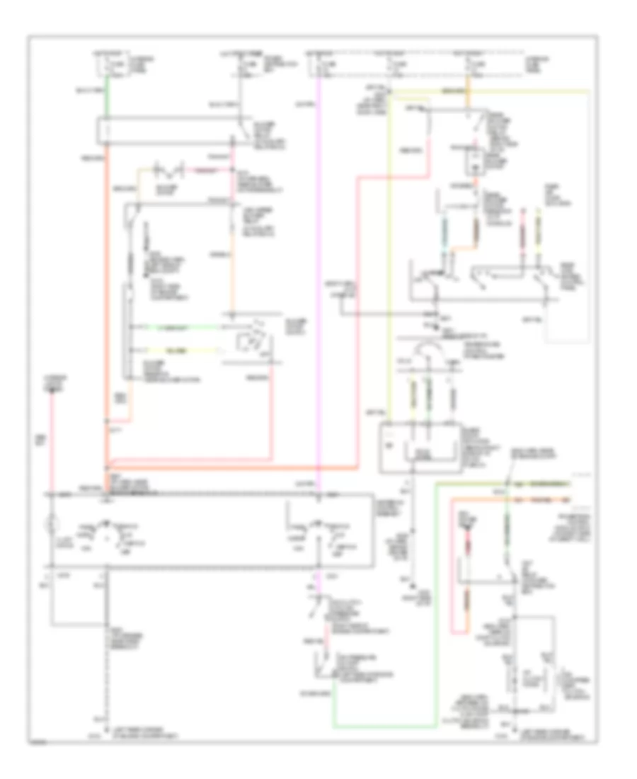
A/C Wiring Diagram, Manual A/C for Mercury Mountaineer 1997
List of elements for A/C Wiring Diagram, Manual A/C for Mercury Mountaineer 1997:
- (body harn, in i/p console)
- (eng harn, between a/c clutch diode & a/c comp clutch solenoid breakout)
- (eng harn, rear of engine compt)
- (in auxiliary relay box 2)
- (left rear corner of engine compartment)
- A/c clutch cycling pressure switch (right side of engine compartment)
- A/c clutch diode
- A/c compres- sor clutch solenoid
- A/c pressure cutoff switch (left side of engine compartment)
- Blend door actuator (behind right side of i/p, on a/c plenum)
- Blower motor
- Blower motor relay (in auxiliary relay box 2)
- Blower motor resistor (near blower motor)
- Blower motor switch
- C231
- C276
- Cold
- Def
- Def/flr
- Flr
- Fuse 15a
- Fuse 50a
- Fuse 7.5a
- G103 (right side of engine compartment)
- G104
- G201 (right side of i/p)
- Heater-a/c control assembly
- High speed blower relay
- Hot at all times
- Hot in run
- Illumi- nation
- Interior fuse panel
- Interior lights system
- Low
- Max
- Med
- Norm
- Off
- Pan/flr
- Panel
- Pcm power relay
- Power distribution box
- Powertrain control module (pcm) (on right side of safety wall)
- Rear air door actuator
- Rear blower motor
- Rear blower motor relay (behind right side of i/p)
- Rear blower motor resistor (in i/p console)
- Rear inte- grated control panel
- Red
- S100
- S133 (eng harn, near a/c comp clutch solenoid)
- S144
- S158 (engine harn, left side of eng compt)
- S170 (i/p harness, near blower motor breakout)
- S171
- S200 (i/p harness, near radio breakout)
- S229 (i/p harn, behind center of i/p)
- S231
- S240 (i/p harn, near right door jamb)
- S257 (i/p harn, near blower motor switch breakout)
- Solid state
- Temperature control potentiometer
- Warm
- Wot a/c relay (in power distribution box)

 Čeština
 Dansk
Dansk Deutsch
 Ελληνικά
 English
 Español
 Suomi
Suomi Français
 Français
 עברית
עברית Hrvatski
 Magyar
 Italiano
 日本語
日本語 한국어
한국어 Nederlands
 Polski
 Português
 Português
 Română
 Русский
 Slovenčina
 Slovenščina
 Svenska
 Türkçe
 中文 (中国)