AIR CONDITIONING
A/C Wiring Diagram for Mercury Tracer LS 1997
 https://portal-diagnostov.com/license.html
Automotive Electricians Portal FZCO
Automotive Electricians Portal FZCO
https://portal-diagnostov.com/license.html
https://portal-diagnostov.com/license.html
Automotive Electricians Portal FZCO
Automotive Electricians Portal FZCO
List of elements for A/C Wiring Diagram for Mercury Tracer LS 1997:
- (behind top of (main harn, left cowl panel) near rear window def sw breakout)
- (dashpanel to headlamp harn, near multi- function switch breakout)
- (engine harn, near brake fluid level switch breakout)
- A/c
- A/c clutch field coil
- A/c low pressure switch (right rear of engine compartment, on accumulator)
- A/c on indi- cator
- A/c switch
- A/c wac relay
- A/c-
- Blower circuit breaker 30a
- Blower motor
- Blower motor relay (left side of i/p)
- Blower motor resistor (behind right side of i/p, in a/c plenum)
- Blower switch
- Breakout)
- C110
- C133
- C138
- C147
- C200
- C220
- C240
- C272
- C273
- Constant control relay module (ccrm) (left front of engine)
- Controls system
- Cooling fan fusible link 40a
- Defrost
- Electric cooling fan
- Engine
- Engine compartment fuse box
- Engine fuse 15a
- Floor flr/def
- Fuel injector fusible link 30a
- Fuel pump relay
- G110 (left front of engine)
- G115 (lower rear of engine)
- G200
- G201 (behind right side of i/p)
- Heater control assembly (integrated control panel) (icp)
- Hfc relay
- Hot at all times
- Hot in run
- Hot in start or run
- I/p fuse panel
- J/c 3
- J/c 6
- Lfc relay
- Lfc relay control
- Max a/c
- Off
- Panel
- Panel floor
- Pcm power relay
- Powertrain control module (pcm) (behind center of i/p)
- Rear wiper fuse 10a
- Red
- S104 (eng harn, near eng compt fuse box breakout)
- S106 (eng harn, near egr vacuum regulator breakout)
- S116 (eng harn, near electric cooling fan breakout)
- S120
- S213
- S234 (dashpanel to headlamp harn, behind left side of i/p)
- Solid state
- Wiper fuse 20a
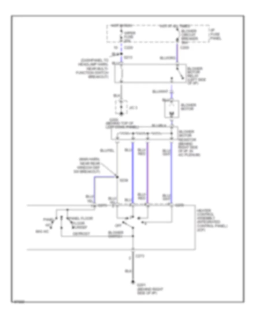
Heater Wiring Diagram for Mercury Tracer LS 1997
List of elements for Heater Wiring Diagram for Mercury Tracer LS 1997:
- (behind top of left cowl panel)
- (dashpanel to headlamp harn, near multi- function switch breakout)
- (main harn, near rear window def sw breakout)
- A/c
- Blower circuit breaker 30a
- Blower motor
- Blower motor relay (left side of i/p)
- Blower motor resistor (behind right side of i/p, in a/c plenum)
- Blower switch
- C200
- C220
- C272
- C273
- Defrost
- Floor flr/def
- G200
- G201 (behind right side of i/p)
- Heater control assembly (integrated control panel) (icp)
- Hot at all times
- Hot in run
- I/p fuse panel
- J/c 3
- Max a/c
- Off
- Panel
- Panel floor
- S213
- S238
- Wiper fuse 20a

 Čeština
 Dansk
Dansk Deutsch
 Ελληνικά
 English
 Español
 Suomi
Suomi Français
 Français
 עברית
עברית Hrvatski
 Magyar
 Italiano
 日本語
日本語 한국어
한국어 Nederlands
 Polski
 Português
 Português
 Română
 Русский
 Slovenčina
 Slovenščina
 Svenska
 Türkçe
 中文 (中国)