AIR CONDITIONING
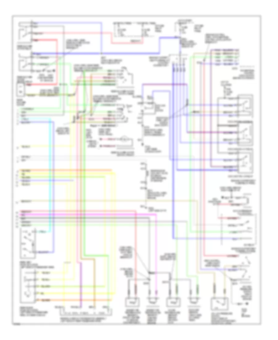
A/C Wiring Diagram, Auto A/C (1 of 2) for Mercury Villager GS 1997
 https://portal-diagnostov.com/license.html
Automotive Electricians Portal FZCO
Automotive Electricians Portal FZCO
https://portal-diagnostov.com/license.html
https://portal-diagnostov.com/license.html
Automotive Electricians Portal FZCO
Automotive Electricians Portal FZCO
List of elements for A/C Wiring Diagram, Auto A/C (1 of 2) for Mercury Villager GS 1997:
- (center of i/p)
- (main harn, behind right side of i/p)
- (right side of i/p)
- Acc
- All times
- Autolamp module
- Blower motor
- Blw fuse 65a
- C2027
- C2028
- C2029
- C212
- E/m switch
- Eatc module
- Electronic automatic temperature control module (center of i/p)
- Engine compart- ment fuse/ relay panel
- F/r door
- F/r door actuator
- Floor/panel
- Fresh/recirculation door actuator (behind right side of i/p, on plenum)
- Front blend door actuator (behind right side of i/p, on plenum)
- Front blower motor relay
- Front blower motor/ speed controller
- Frt blend door
- Frt blend door (cool)
- Frt blend door (warm)
- Frt blo motor relay
- Fuse 10a
- Fuse 20a
- Fuse 7.5a
- G201
- G202 (left side of i/p)
- Ground
- Ha01
- Ha02
- Ha04
- Ha06
- Ha09
- Ha11
- Ha12
- Ha13
- Ha14
- Ha15
- Ha16
- Ha17
- Ha18
- Ha20
- Ha21
- Ha22
- Ha23
- Ha24
- Ha28
- Hae2
- Hc02
- Hc03
- Hc04
- Hc05
- Hc06
- Hc08
- Hc09
- Hc10
- Hc11
- Hc12
- Hc13
- Hc14
- Hc15
- Hc16
- Hc17
- Hc18
- Hc19
- Hc20
- Hc21
- Hce2
- Hce5
- Hce7
- Hj02
- Hj03
- Hj05
- Hj06
- Hj07
- Hj10
- Hj12
- Hot at
- Hot at all times
- Hot in run
- I/p fuse/ relay panel
- I/p fuse/relay panel
- Ignition
- Ignition switch
- Ih01
- Ih02
- Ih91
- Illumination
- In car temp sensor
- Instrument cluster
- Interior lights system
- J/c 1 (left i/p)
- Lo pressure
- Lock
- Mode actuator
- Mode actuator (behind center of i/p)
- Nca
- Off
- Pnk
- Position switches
- Power
- Rea water vlv sol
- Rear blend dr act
- Rear climate control panel
- Rear vent door act
- Rr blend door
- Rr blower motor
- Rr blower motor relay
- Rr blw motor sw
- Rr cc panel
- Rr cc power
- Rr cc switch (frt)
- Rr climate ctrl panel
- Run
- S203 (main harn, behind right side of i/p)
- S209
- S231 (main harn, behind right side of i/p)
- S236 (main harn, near front blower motor breakout)
- S249 (main harn, behind right side of i/p)
- S315
- S316
- Sensor input
- Sensor power
- Side of i/p)
- Start
- Sunload sensor
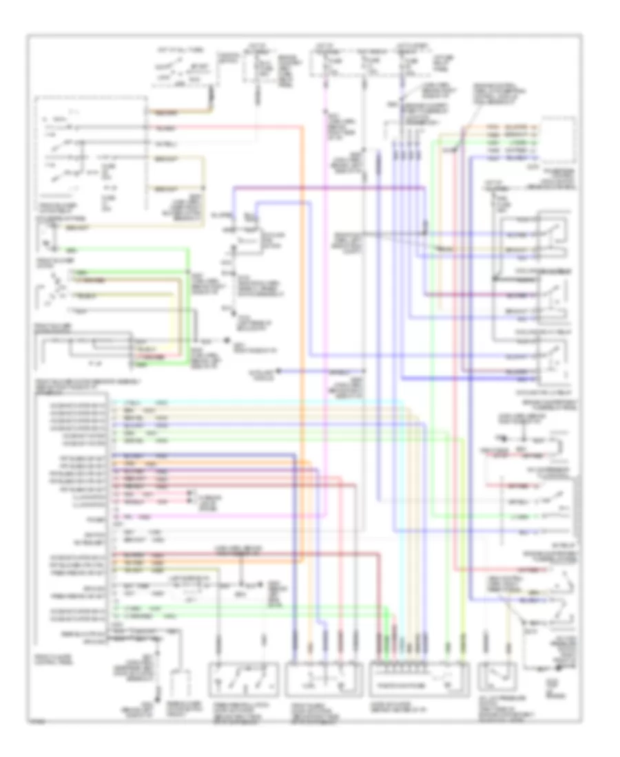
A/C Wiring Diagram, Auto A/C (2 of 2) for Mercury Villager GS 1997
List of elements for A/C Wiring Diagram, Auto A/C (2 of 2) for Mercury Villager GS 1997:
- (center rear of engine)
- (eng control harn, right rear of eng)
- (eng room harn, left side of eng compt)
- (engine control harn, in powertrain control module (pcm) breakout)
- (front center
- (main harn, behind center of i/p)
- (main harn, behind left side of i/p)
- (main harn, behind right side of i/p)
- (main harn, near elect auto temp module breakout)
- (main harn, near left cowl panel)
- (main harn, near rear blower motor resistor assembly breakout)
- (main harn, near rear blower motor switch relay breakout)
- (right side
- (sub harn (eatc), behind center of i/p)
- A/c compressor clutch coil
- A/c high pressure switch (right front of engine)
- A/c low pressure switch (right side of engine compartment, on accumulator)
- A/c relay
- Ambient air temperature sensor 1
- Ambient air temperature sensor 2
- C275
- Compartment)
- Cooling fan hi1 relay
- Cooling fan hi2 relay
- Cooling fan lo relay
- Cooling fan motor
- Engine compart- ment fuse/relay junction connector 1
- Engine compartment fuse/relay panel
- Fa06
- Fa12
- Fuse 10a
- Fuse 15a
- G104 (left rear of eng compt)
- G134 (top of engine)
- G201
- G202 (left side of i/p)
- G202 (left side of i/p)
- G407 (center rear of vehicle)
- Ha41
- Ha45
- Hot at all times
- Hot in start or run
- Hx01
- I/p fuse/ relay panel
- In-car
- Interior lights system
- Nca
- Of engine
- Of i/p)
- Off
- Pnk
- Powertrain control module (pcm) (behind glove box)
- Rad fuse 65a
- Rear
- Rear blend door actuator (left side of passenger area, on rear plenum)
- Rear blower motor
- Rear blower motor relay
- Rear blower motor resistor assembly (left side of rear passenger area)
- Rear blower motor switch (front)
- Rear blower motor switch (rear)
- Rear blower motor switch relay
- Rear engine coolant valve solenoid (center rear of engine)
- Rear vent door actuator (left side of passenger area)
- Red
- S102 (eng room harn, near oil press switch breakout)
- S135
- S158
- S159
- S2015
- S210 (eng cntrl harn, right front of engine)
- S212
- S219
- S224 (main harn, behind right side of i/p)
- S237 (main harn, behind right side of i/p)
- S251
- S253 (main harn, near elect auto temp cntrl breakout)
- S288
- S289
- S290
- S304
- S311
- S313
- S314
- S318
- Sensor (behind ashtray, in i/p)
- Sunload sensor (right side of cargo area)
- Temperature
A/C Wiring Diagram, Manual A/C for Mercury Villager GS 1997
List of elements for A/C Wiring Diagram, Manual A/C for Mercury Villager GS 1997:
- (eng control harn, right rear of eng)
- (eng room harn, left side of eng compt)
- (engine control harn, in powertrain control module (pcm) breakout)
- (left rear of eng compt)
- (left side of i/p)
- (main harn, behind right side of i/p)
- (right side of i/p)
- A/c compressor clutch coil
- A/c high pressure switch (right front of engine)
- A/c low pressure switch (right side of engine compartment, on accumulator)
- A/c relay
- A/c request
- Acc
- All times
- Autolamp module
- Blw fuse 65a
- C201
- C203
- C275
- Cooling fan hi1 relay
- Cooling fan hi2 relay
- Cooling fan lo relay
- Cooling fan motor
- Engine compart- ment fuse/ relay panel
- Engine compart- ment fuse/relay junction connector 1
- Engine compartment fuse/relay panel
- Fa06
- Fa12
- Fresh/recirc dr act
- Fresh/recirculation door actuator (behind right side of i/p, on plenum)
- Front blend door actuator (behind right side of i/p, on plenum)
- Front blower motor
- Front blower motor relay
- Front blower motor resistor assembly (behind right side of i/p, in plenum)
- Front blower motor switch
- Front climate control panel
- Frt blend dr act
- Frt blend dr mtr act
- Frt blower mtr ctrl
- Fuse 10a
- Fuse 20a
- Fuse 7.5a
- G104
- G134 (top of engine)
- G201
- G201 (right side of i/p)
- G202 (behind left side of i/p)
- Ground
- Ha01
- Ha02
- Ha04
- Ha05
- Ha06
- Ha09
- Ha11
- Ha12
- Ha13
- Ha14
- Ha15
- Ha16
- Ha17
- Ha18
- Ha20
- Ha21
- Ha22
- Ha23
- Ha24
- Ha28
- Ha41
- Ha45
- Hae4
- Hb21
- He01
- Hot at
- Hot at all times
- Hot in run
- Hot in start or run
- Hx01
- I/p fuse/ relay panel
- I/p fuse/relay panel
- Ignition
- Ignition switch
- Ih01
- Ih91
- Illumination
- Interior lights system
- J/c 1
- Lock
- Mode act motor
- Mode actuator (behind center of i/p)
- Mode actuator sw in
- Nca
- Off
- Pnk
- Position switches
- Power
- Powertrain control module (pcm) (behind glove box)
- Rad fuse 65a
- Rear blower motor switch (front)
- Rear blw mtr sw
- Run
- S102 (eng room harn, near oil press switch breakout)
- S135
- S158
- S159
- S203
- S219
- S231 (main harn, behind right side of i/p)
- S236 (main harn, near front blower motor breakout)
- S248 (main harn, behind left side of i/p)
- S249 (main harn, behind right side of i/p)
- S251
- S287 (main harn, behind right side of i/p)
- S301 (main harn, near rear vent door actuator breakout)
- Start
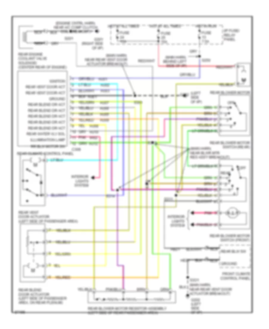
Rear A/C Wiring Diagram, Manual A/C for Mercury Villager GS 1997
List of elements for Rear A/C Wiring Diagram, Manual A/C for Mercury Villager GS 1997:
- (engine cntrl harn, near a/c comp clutch coil breakout)
- (left side of i/p)
- (main harn, behind left side of i/p)
- (main harn, near blwr mtr res ass'y breakout)
- (main harn, near rear vent door actuator breakout)
- C308
- Front climate control panel
- Fuse 15a
- Fuse 7.5a
- G201 (right side of i/p)
- G202
- G202 (left side of i/p)
- Ground
- Hb21
- He01
- Hj01
- Hj02
- Hj03
- Hj05
- Hj06
- Hj07
- Hj08
- Hj09
- Hj10
- Hj12
- Hje1
- Hot at all times
- Hot in run
- I/p fuse/ relay panel
- Ignition
- Ih02
- Illumination lamp
- Interior lights system
- Nca
- Nca ground
- Nca rear blw sw
- Off
- Pnk
- Rear
- Rear blend door actuator (left side of passenger area, on rear plenum)
- Rear blend dr act
- Rear blower motor
- Rear blower motor resistor assembly (left side of rear passenger area)
- Rear blower motor switch (front)
- Rear blower motor switch (rear)
- Rear climate control panel
- Rear engine coolant valve solenoid (center rear of engine)
- Rear vent door act
- Rear vent door actuator (left side of passenger area)
- Rear water vlv sol
- Rr blw motor sw
- S201
- S250
- S301
- S311
- S313
- S314
- S318
- S3o1

 Čeština
 Dansk
Dansk Deutsch
 Ελληνικά
 English
 Español
 Suomi
Suomi Français
 Français
 עברית
עברית Hrvatski
 Magyar
 Italiano
 日本語
日本語 한국어
한국어 Nederlands
 Polski
 Português
 Português
 Română
 Русский
 Slovenčina
 Slovenščina
 Svenska
 Türkçe
 中文 (中国)