AIR CONDITIONING
3.0L
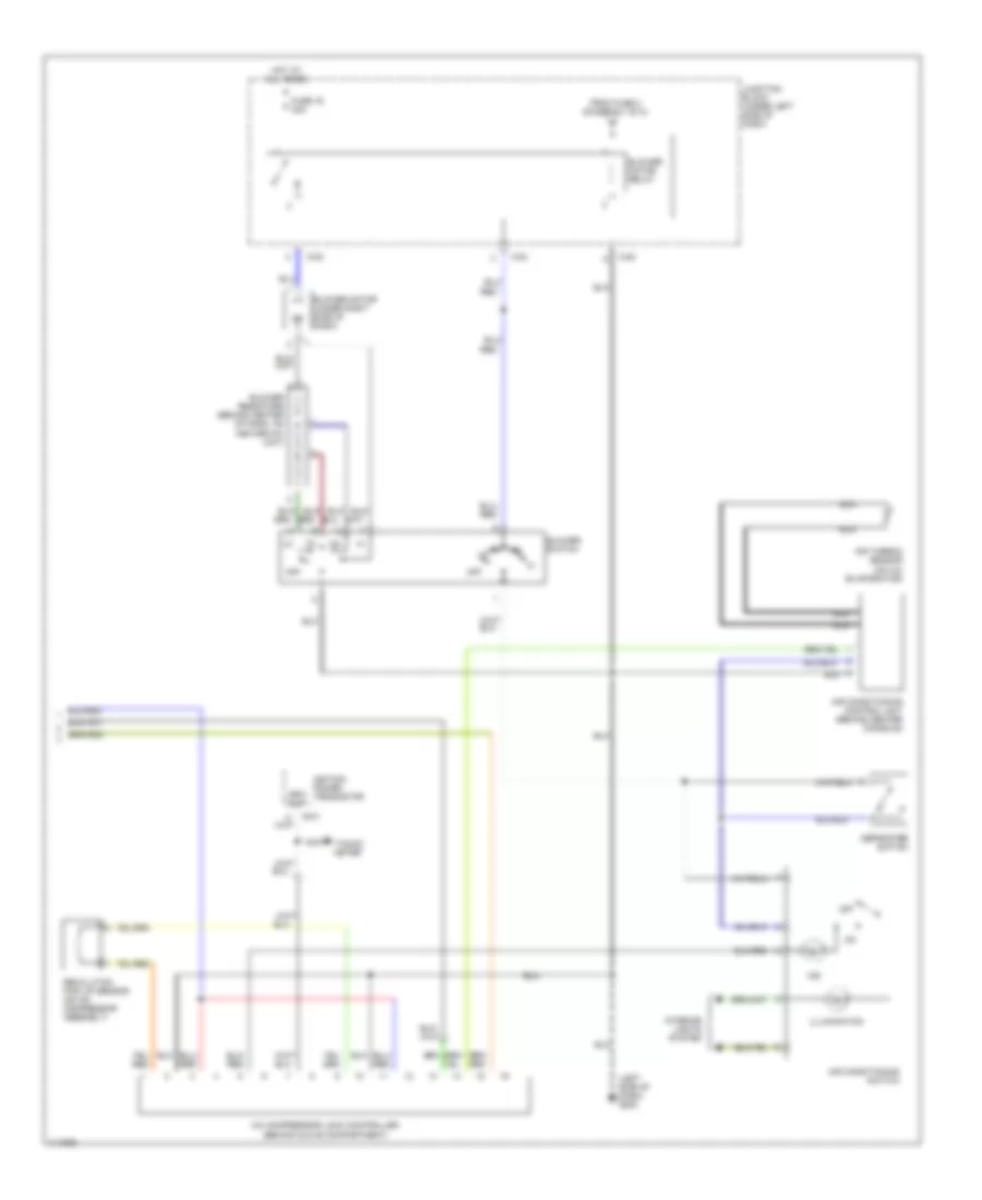
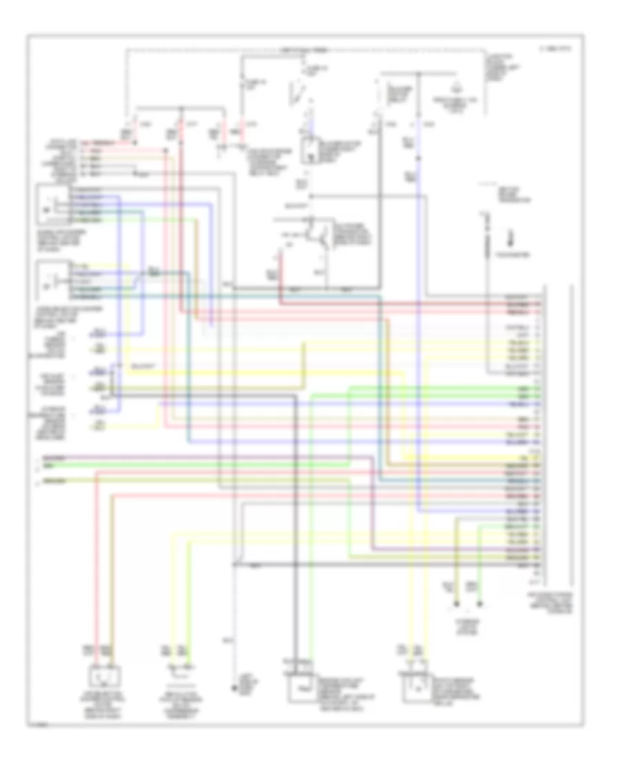
3.0L DOHC, Manual A/C Wiring Diagram (1 of 2) for Mitsubishi 3000GT VR-4 1999
 https://portal-diagnostov.com/license.html
Automotive Electricians Portal FZCO
Automotive Electricians Portal FZCO
https://portal-diagnostov.com/license.html
https://portal-diagnostov.com/license.html
Automotive Electricians Portal FZCO
Automotive Electricians Portal FZCO
List of elements for 3.0L DOHC, Manual A/C Wiring Diagram (1 of 2) for Mitsubishi 3000GT VR-4 1999:
- (left front fender) g100
- (open above
- (open below
- (right front fender) g101
- (right side of firewall) g123
- 28 psi)
- 455 psi)
- A/c relay box (dedicated fuses) (on left side of engine compartment, in front of shock tower)
- A/c relay box (on left side of engine compartment, in front of shock tower)
- A/t only
- All times
- C-46
- C-52
- C-53
- C-54
- C-69
- C-71
- C-83
- Condenser fan motor
- Condenser fan motor relay (hi)
- Condenser fan motor relay (lo)
- Dual pressure switch (left side of engine compartment)
- Elc-4 a/t control module (behind center console)
- Engine compartment relay box (on right side of engine compartment near shock tower)
- Engine compartment relay box (on right side of engine compartment, near shock tower)
- Engine control module (behind center console)
- Engine coolant temperature sensor (on right rear of engine)
- Fuse 11 15a
- Fuse 3 10a
- Fuse 8 20a
- Fuse 9 10a
- Fusible link 5 40a
- Hot at
- Hot in on
- Hot in on or start
- Junction block (under left side of dash)
- Magnetic clutch (on compressor)
- Magnetic clutch relay
- Radiator fan motor (on right front of engine compartment)
- Radiator fan relay (hi)
- Radiator fan relay (lo)
- Resistor (part of radiator fan assembly)
- Solid state
- Speed sensor (right side of transaxle)
- To blower relay (diagram 2 of 2)
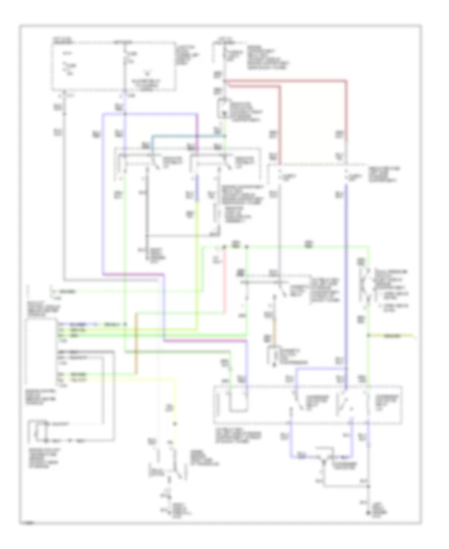
3.0L DOHC, Manual A/C Wiring Diagram (2 of 2) for Mitsubishi 3000GT VR-4 1999
List of elements for 3.0L DOHC, Manual A/C Wiring Diagram (2 of 2) for Mitsubishi 3000GT VR-4 1999:
- (left side of dash) g202
- A/c compressor lock controller (behind glove compartment)
- Air conditioning control unit (behind center console)
- Air conditioning switch
- Air thermo sensor (on a/c evaporator)
- B-21
- Blower motor (under right side of dash)
- Blower motor relay
- Blower resistors (behind center of dash, on heater-a/c unit)
- Blower switch
- C-82
- C-83
- Defroster switch
- From fuse 3 (diagram 1 of 2)
- Fuse 16 30a
- Hot at all times
- Ignition power transistor
- Illumination
- Ind
- Interior lights system
- Junction block (under left side of dash)
- Nca
- Off
- Red
- Revolution pick up sensor (on a/c compressor assembly)
- Rpm out
- Tacho- meter
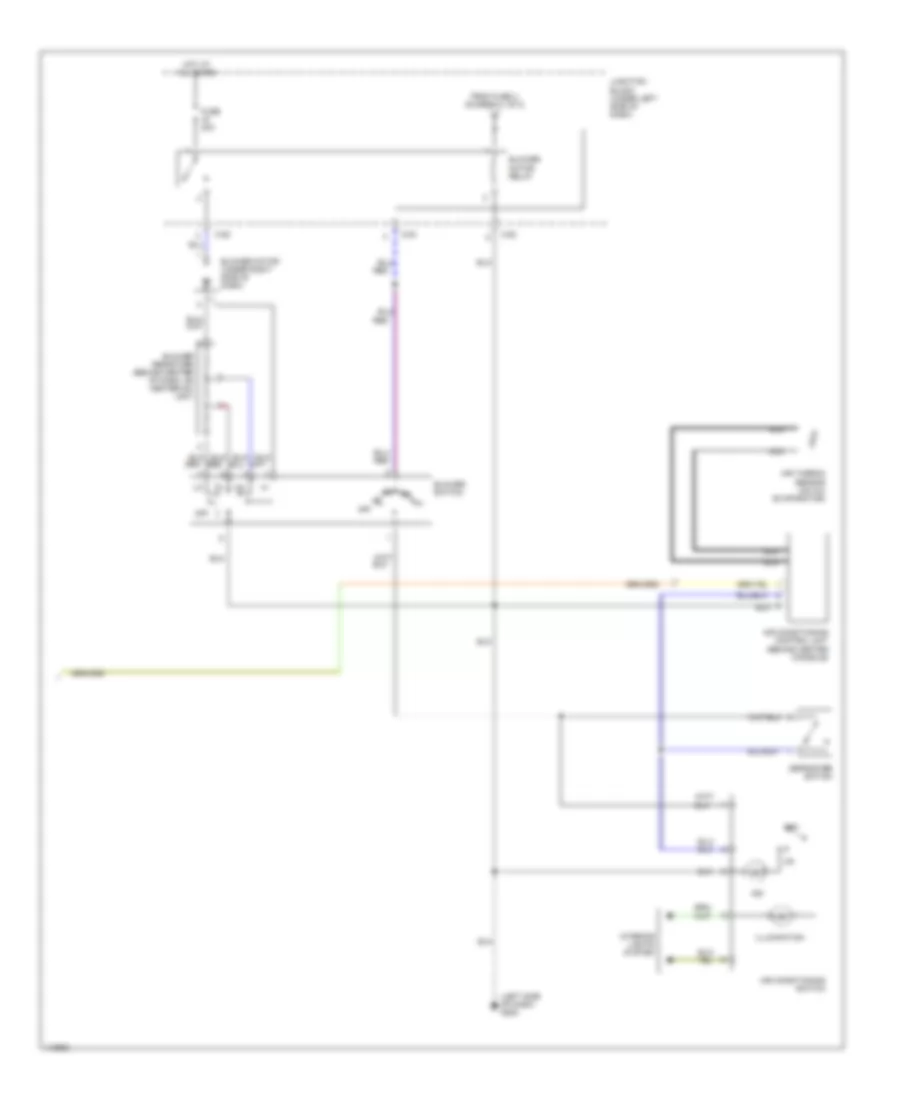
3.0L SOHC, Manual A/C Wiring Diagram (1 of 2) for Mitsubishi 3000GT VR-4 1999
List of elements for 3.0L SOHC, Manual A/C Wiring Diagram (1 of 2) for Mitsubishi 3000GT VR-4 1999:
- (left front fender) g100
- (open above 28 psi)
- (open above 455 psi)
- (right front fender) g101
- (right side of firewall) g123
- (to diagram 2 of 2)
- A/c relay box (on left side of engine compartment, in front of shock tower)
- A/t only
- All times
- Blower relay
- C-46
- C-52
- C-53
- C-54
- C-69
- C-71
- Condenser fan motor
- Condensor fan motor relay (hi)
- Condensor fan motor relay (lo)
- Dedicated fuse (left side of engine compartment)
- Dual pressure switch (left side of engine compartment)
- Elc-4 a/t control module (behind center console)
- Engine compartment relay box (on right side of engine compartment near shock tower)
- Engine compartment relay box (on right side of engine compartment, near shock tower)
- Engine control module (behind center console)
- Engine coolant temperature sensor (on right rear of engine)
- Fuse 10a
- Fuse 15a
- Fuse 8 20a
- Fuse 9 10a
- Fusible link 5 40a
- Hot at
- Hot in on
- Hot in on or start
- Junction block (under left side of dash)
- Magnetic clutch (on compressor)
- Magnetic clutch relay
- Radiator fan motor (on right front of engine compartment)
- Radiator fan relay (hi)
- Radiator fan relay (lo)
- Resistor (part of radiator fan assembly)
- Solid state
- Speed sensor (right side of transaxle)
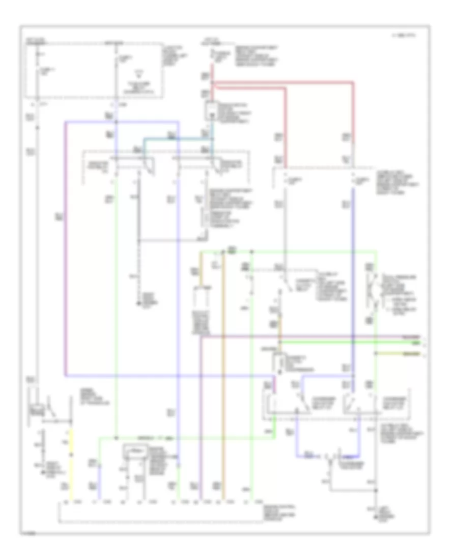
3.0L SOHC, Manual A/C Wiring Diagram (2 of 2) for Mitsubishi 3000GT VR-4 1999
List of elements for 3.0L SOHC, Manual A/C Wiring Diagram (2 of 2) for Mitsubishi 3000GT VR-4 1999:
- (left side of dash) g202
- Air conditioning control unit (behind center console)
- Air conditioning switch
- Air thermo sensor (on a/c evaporator)
- Blower motor (under right side of dash)
- Blower motor relay
- Blower resistors (behind center of dash, on heater-a/c unit)
- Blower switch
- C-82
- C-83
- Defroster switch
- From fuse 3, (diagram 1 of 2)
- Fuse 30a
- Hot at all times
- Illumination
- Ind
- Interior lights system
- Junction block (under left side of dash)
- Nca
- Off
- Red
Automatic A/C Wiring Diagram (1 of 2) for Mitsubishi 3000GT VR-4 1999
List of elements for Automatic A/C Wiring Diagram (1 of 2) for Mitsubishi 3000GT VR-4 1999:
- (left front fender) g100
- (open above
- (open below
- (right front fender) g101
- (right side of firewall) g123
- 28 psi)
- 455 psi)
- A/c relay box (dedicated fuses) (on left side of engine compartment, in front of shock tower)
- A/c relay box (on left side of engine compartment, in front of shock tower)
- A/t only
- All times
- C 1995 vftc
- C-46
- C-52
- C-53
- C-54
- C-69
- C-71
- Condenser fan motor
- Condenser fan motor relay (hi)
- Condenser fan motor relay (lo)
- Dual pressure switch (left side of engine compartment)
- Elc-4 a/t control module (behind center console)
- Engine compartment relay box (on right side of engine compartment, near shock tower)
- Engine control module (behind center console)
- Engine coolant temperature sensor (on right rear of engine)
- Fuse 11 15a
- Fuse 3 10a
- Fuse 8 20a
- Fuse 9 10a
- Fusible link 5 40a
- Hot at
- Hot in on
- Hot in on or start
- Junction block (under left side of dash)
- Magnetic clutch (on compressor)
- Magnetic clutch relay
- Radiator fan motor (on right front of engine compartment)
- Radiator fan relay (hi)
- Radiator fan relay (lo)
- Resistor (part of radiator fan assembly)
- Solid state
- Speed sensor (right side of transaxle)
- To blower relay (diagram 2 of 2)
Automatic A/C Wiring Diagram (2 of 2) for Mitsubishi 3000GT VR-4 1999
List of elements for Automatic A/C Wiring Diagram (2 of 2) for Mitsubishi 3000GT VR-4 1999:
- (behind center of dash)
- (left side of dash) g202
- (under dash, right of steering column)
- A/c power transistor (behind right side of dash)
- Air conditioning control unit (behind center console)
- Air inlet sensor (in blower housing)
- Air selection damper control motor (behind right side of dash)
- Air thermo sensor (on a/c evaporator)
- Blend air damper control motor (behind center of dash)
- Blower motor (under right side of dash)
- Blower motor relay
- C 1995 vftc
- C-16
- C-17
- C-70
- C-77
- C-82
- C-83
- Connector (dlc) 1 (partial)
- Control motor
- Data link
- Engine coolant temperature sensor (behind left side of glove box, on heater-a/c box)
- From fuse 3, 10a (diagram 1 of 2)
- Fuse 16 30a
- Fuse 19 10a
- Hot at all times
- Ignition power transistor
- Interior lights system
- Interior temperature sensor (on rear center of headliner)
- Iod or storage connector (in engine compartment relay box)
- Junction block (under left side of dash)
- Mode selection damper
- Nca
- Photo sensor (on top right of dashboard, near defroster grille)
- Pnk
- Red
- Revolution pick-up sensor (on a/c compressor assembly)
- Tachometer

 Čeština
 Dansk
Dansk Deutsch
 Ελληνικά
 English
 Español
 Suomi
Suomi Français
 Français
 עברית
עברית Hrvatski
 Magyar
 Italiano
 日本語
日本語 한국어
한국어 Nederlands
 Polski
 Português
 Português
 Română
 Русский
 Slovenčina
 Slovenščina
 Svenska
 Türkçe
 中文 (中国)