AIR CONDITIONING
2.0L
2.0L, Automatic A/C Wiring Diagram (1 of 3) for Mitsubishi Lancer DE 2009
 https://portal-diagnostov.com/license.html
Automotive Electricians Portal FZCO
Automotive Electricians Portal FZCO
https://portal-diagnostov.com/license.html
https://portal-diagnostov.com/license.html
Automotive Electricians Portal FZCO
Automotive Electricians Portal FZCO
List of elements for 2.0L, Automatic A/C Wiring Diagram (1 of 3) for Mitsubishi Lancer DE 2009:
- A/c-ecu (behind center of dash)
- Air mixing damper control motor (under right side of dash)
- Ambient temperature sensor (left front of engine compt)
- Analog interface circuit
- Blower motor (under right side of dash)
- Blower relay
- C-19
- C-20
- C-312
- C-315
- C-317
- Computer data lines system
- Etacs-ecu (on rear of junction block, behind left end of dash)
- Fuse 30a
- Fuse 7.5a
- G4 (behind right kick panel)
- Hot at all times
- Hot w/ ig1 relay energized
- Mode selection damper control motor (behind right side of dash)
- Outside/inside selection damper control module (behind right side of dash)
- Red
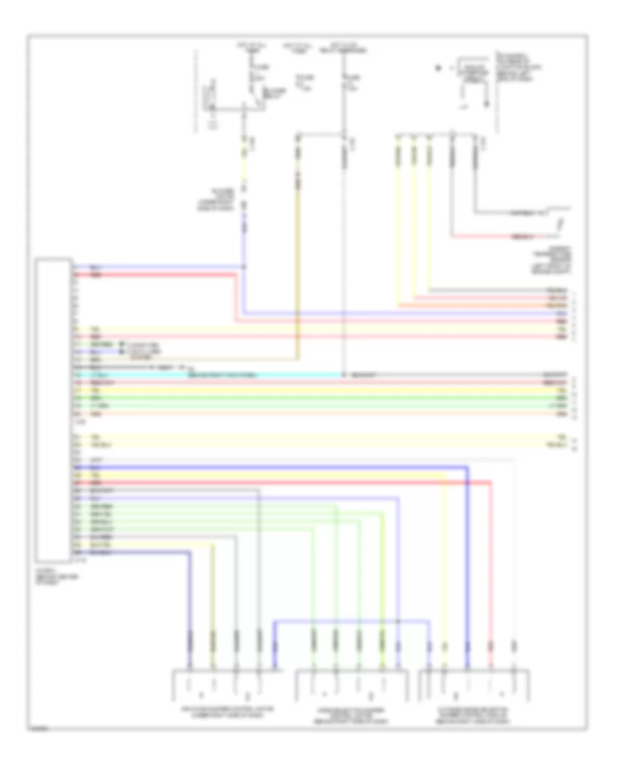
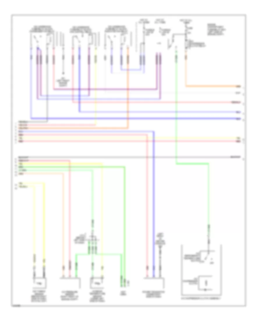
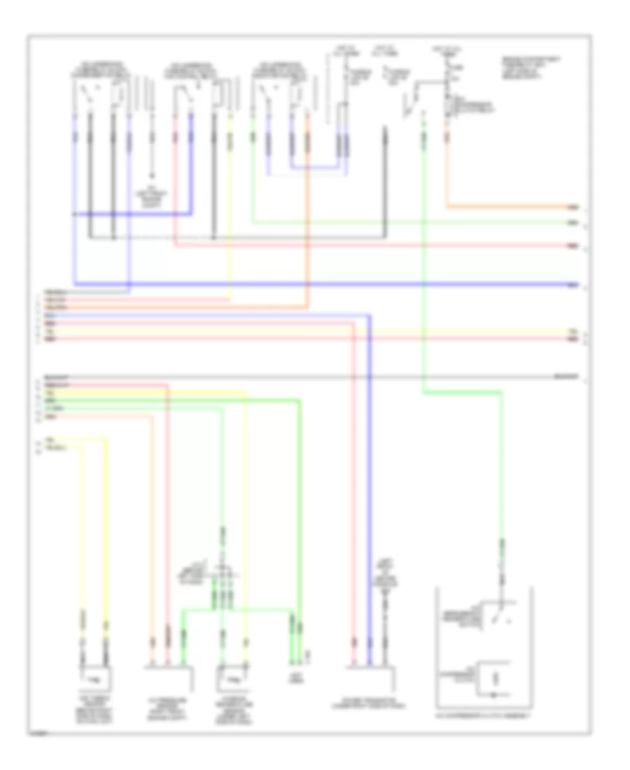
2.0L, Automatic A/C Wiring Diagram (2 of 3) for Mitsubishi Lancer DE 2009
List of elements for 2.0L, Automatic A/C Wiring Diagram (2 of 3) for Mitsubishi Lancer DE 2009:
- (left front of center console) g15
- (not used)
- (on underhood fuse/relay block) condenser fan relay
- (on underhood fuse/relay block) fan control relay
- (on underhood fuse/relay block) radiator fan relay
- A/c compressor clutch
- A/c compressor clutch assembly
- A/c compressor clutch relay
- A/c pressure sensor (right front engine compt)
- A/c refrigerant temperature switch
- Air thermo sensor (behind right side of dash, on hvac unit)
- C-101
- Engine compartment fuse/relay box (left side of engine compt)
- Fuse 10a
- Fusible link 28 30a
- Fusible link 29 40a
- G17 (left front engine compt)
- Hot at all times
- Interior temperature sensor (under left side of dash)
- J/c 2 (behind left side of dash)
- Nca
- Power transistor (under right side of dash)
- Red
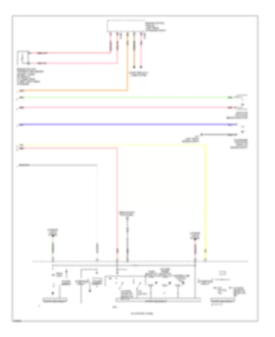
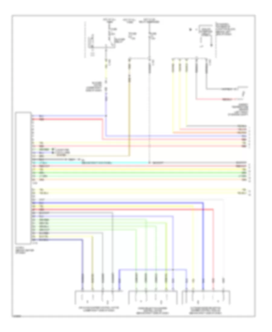
2.0L, Automatic A/C Wiring Diagram (3 of 3) for Mitsubishi Lancer DE 2009
List of elements for 2.0L, Automatic A/C Wiring Diagram (3 of 3) for Mitsubishi Lancer DE 2009:
- (behind right kick panel) g4
- A/c control panel
- A/c switch
- A/c switch ind
- B-108
- B-109
- Back light
- Blower speed selection dial
- Computer data lines system
- Condenser fan motor (front of engine compt)
- Cpu
- Engine control module (left rear of engine compt)
- Engine coolant temperature sensor (except turbo: on rear of cylinder head) (turbo: right rear of engine)
- G17 (left front engine compt)
- Interface circuit
- Interior lights system
- Mode selection dial
- Outside/ inside air selection ind
- Outside/ inside air selection switch
- Pnk
- Radiator fan motor (behind radiator)
- Red
- Temperature control dial
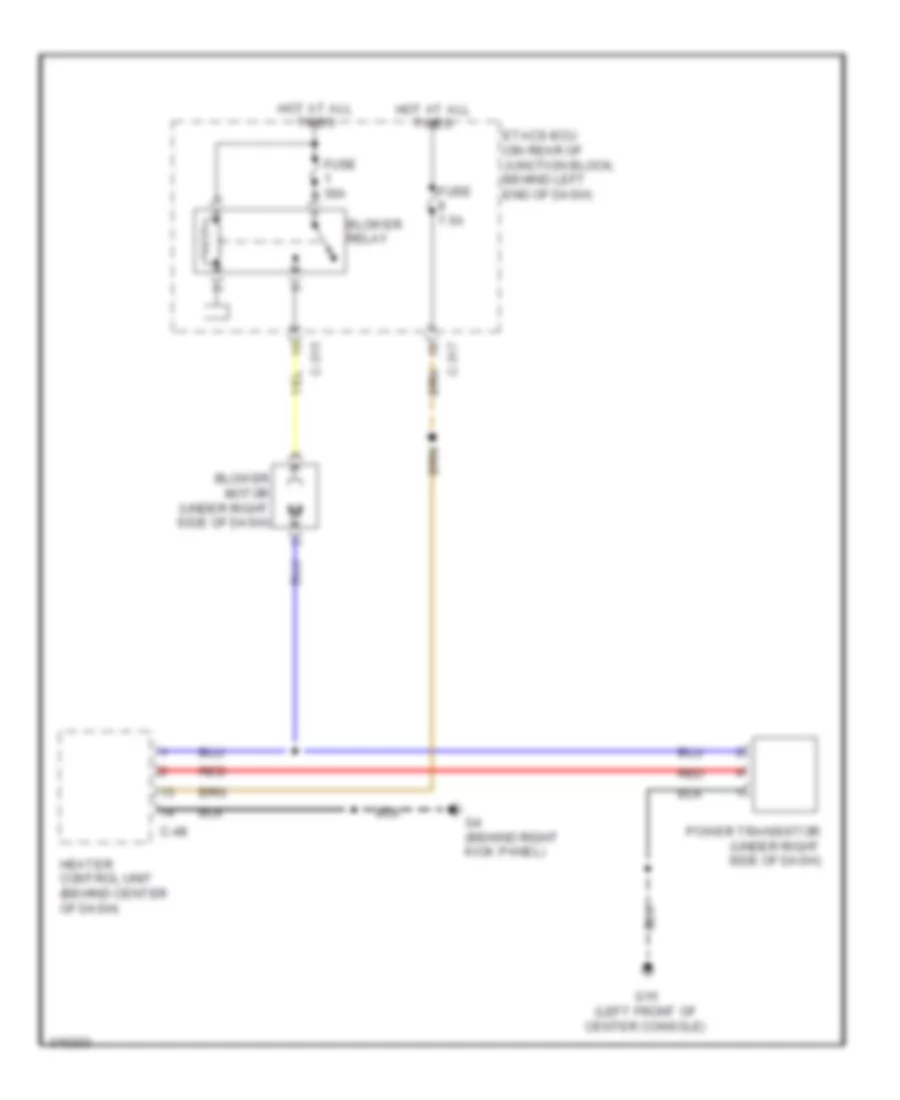
2.0L, Heater Wiring Diagram for Mitsubishi Lancer DE 2009
List of elements for 2.0L, Heater Wiring Diagram for Mitsubishi Lancer DE 2009:
- Blower motor (under right side of dash)
- Blower relay
- C-315
- C-317
- C-48
- Etacs-ecu (on rear of junction block, behind left end of dash)
- Fuse 30a
- Fuse 7.5a
- G15 (left front of center console)
- G4 (behind right kick panel)
- Heater control unit (behind center of dash)
- Hot at all times
- Power transistor (under right side of dash)
- Red
2.0L, Manual A/C Wiring Diagram (1 of 3) for Mitsubishi Lancer DE 2009
List of elements for 2.0L, Manual A/C Wiring Diagram (1 of 3) for Mitsubishi Lancer DE 2009:
- Air mixing damper control motor (under right side of dash)
- Ambient temperature sensor (left front of engine compt)
- Analog interface circuit
- Blower motor (under right side of dash)
- Blower relay
- C-312
- C-315
- C-317
- C-48
- C-49
- Computer data lines system
- Etacs-ecu (on rear of junction block, behind left end of dash)
- Fuse 30a
- Fuse 7.5a
- G4 (behind right kick panel)
- Heater control unit (behind center of dash)
- Hot at all times
- Hot w/ ig1 relay energized
- Mode selection damper control motor (behind right side of dash)
- Outside/inside selection damper control module (behind right side of dash)
- Red
2.0L, Manual A/C Wiring Diagram (2 of 3) for Mitsubishi Lancer DE 2009
List of elements for 2.0L, Manual A/C Wiring Diagram (2 of 3) for Mitsubishi Lancer DE 2009:
- (left front of center console) g15
- (not used)
- (on underhood fuse/relay block) condenser fan relay
- (on underhood fuse/relay block) fan control relay
- (on underhood fuse/relay block) radiator fan relay
- A-42
- A/c compressor clutch
- A/c compressor clutch assembly
- A/c compressor clutch relay
- A/c refrigerant temperature switch
- Air thermo sensor (behind right side of dash, on hvac unit)
- C-08
- C-101
- Engine compartment fuse/relay box (left side of engine compt)
- Fuse 10a
- Fusible link 28 30a
- Fusible link 29 40a
- G17 (left front engine compt)
- Hot at all times
- J/c 2 (behind left side of dash)
- Nca
- Power transistor (under right side of dash)
- Red
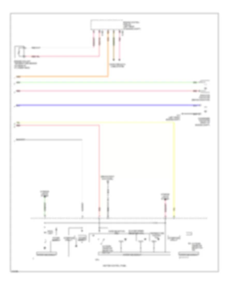
2.0L, Manual A/C Wiring Diagram (3 of 3) for Mitsubishi Lancer DE 2009
List of elements for 2.0L, Manual A/C Wiring Diagram (3 of 3) for Mitsubishi Lancer DE 2009:
- (behind right kick panel) g4
- B-108
- B-109
- Back light
- Blower speed selection dial
- Computer data lines system
- Condenser fan motor (front of engine compt)
- Cpu
- Engine control module (left rear of engine compt)
- Engine coolant temperature sensor (on rear of cylinder head)
- G17 (left front engine compt)
- Heater control panel
- Interface circuit
- Interior lights system
- Mode selection dial
- Outside/ inside air selection ind
- Outside/ inside air selection switch
- Pnk
- Radiator fan motor (behind radiator)
- Red
- Temperature control dial
2.0L TURBO
2.0L Turbo, Automatic A/C Wiring Diagram (1 of 3) for Mitsubishi Lancer DE 2009
List of elements for 2.0L Turbo, Automatic A/C Wiring Diagram (1 of 3) for Mitsubishi Lancer DE 2009:
- A/c-ecu (behind center of dash)
- Air mixing damper control motor (under right side of dash)
- Ambient temperature sensor (left front of engine compt)
- Analog interface circuit
- Blower motor (under right side of dash)
- Blower relay
- C-19
- C-20
- C-312
- C-315
- C-317
- Computer data lines system
- Etacs-ecu (on rear of junction block, behind left end of dash)
- Fuse 30a
- Fuse 7.5a
- G4 (behind right kick panel)
- Hot at all times
- Hot w/ ig1 relay energized
- Mode selection damper control motor (behind right side of dash)
- Outside/inside selection damper control module (behind right side of dash)
- Red
2.0L Turbo, Automatic A/C Wiring Diagram (2 of 3) for Mitsubishi Lancer DE 2009
List of elements for 2.0L Turbo, Automatic A/C Wiring Diagram (2 of 3) for Mitsubishi Lancer DE 2009:
- (left front of center console) g15
- (not used)
- (on underhood fuse/relay block) condenser fan relay
- (on underhood fuse/relay block) fan control relay
- (on underhood fuse/relay block) radiator fan relay
- A/c compressor clutch
- A/c compressor clutch assembly
- A/c compressor clutch relay
- A/c pressure sensor (right front of engine compt)
- A/c refrigerant temperature switch
- Air thermo sensor (behind right side of dash, on hvac unit)
- C-101
- Engine compartment fuse/relay box (left side of engine compt)
- Fuse 10a
- Fusible link 28 30a
- Fusible link 29 40a
- G17 (left front engine compt)
- Hot at all times
- Interior temperature sensor (under left side of dash)
- J/c 2 (behind left side of dash)
- Nca
- Off
- Power transistor (under right side of dash)
- Red
2.0L Turbo, Automatic A/C Wiring Diagram (3 of 3) for Mitsubishi Lancer DE 2009
List of elements for 2.0L Turbo, Automatic A/C Wiring Diagram (3 of 3) for Mitsubishi Lancer DE 2009:
- (behind radiator) radiator fan motor
- (behind right kick panel) g4
- (left front engine compt) g17
- A/c control panel
- A/c switch
- A/c switch ind
- B-108
- B-109
- Back light
- Blower speed selection dial
- Computer data lines system
- Condenser fan motor (front of engine compt)
- Cpu
- Engine control module (left rear of engine compt)
- Engine coolant temperature sensor (right rear of engine)
- Interface circuit
- Interior lights system
- Mode selection dial
- Nca
- Off
- Outside/ inside air selection ind
- Outside/ inside air selection switch
- Red
- Temperature control dial
2.4L
2.4L, Automatic A/C Wiring Diagram (1 of 3) for Mitsubishi Lancer DE 2009
List of elements for 2.4L, Automatic A/C Wiring Diagram (1 of 3) for Mitsubishi Lancer DE 2009:
- A/c-ecu (behind center of dash)
- Air mixing damper control motor (under right side of dash)
- Ambient temperature sensor (left front of engine compt)
- Analog interface circuit
- Blower motor (under right side of dash)
- Blower relay
- C-19
- C-20
- C-312
- C-315
- C-317
- Computer data lines system
- Etacs-ecu (on rear of junction block, behind left end of dash)
- Fuse 30a
- Fuse 7.5a
- G4 (behind right kick panel)
- Hot at all times
- Hot w/ ig1 relay energized
- Mode selection damper control motor (behind right side of dash)
- Outside/inside selection damper control module (behind right side of dash)
- Red
2.4L, Automatic A/C Wiring Diagram (2 of 3) for Mitsubishi Lancer DE 2009
List of elements for 2.4L, Automatic A/C Wiring Diagram (2 of 3) for Mitsubishi Lancer DE 2009:
- (left front of center console) g15
- (not used)
- (on underhood fuse/relay block) condenser fan relay
- (on underhood fuse/relay block) fan control relay
- (on underhood fuse/relay block) radiator fan relay
- A/c compressor clutch
- A/c compressor clutch assembly
- A/c compressor clutch relay
- A/c pressure sensor (right front engine compt)
- A/c refrigerant temperature switch
- Air thermo sensor (behind right side of dash, on hvac unit)
- C-101
- Engine compartment fuse/relay box (left side of engine compt)
- Fuse 10a
- Fusible link 28 30a
- Fusible link 29 40a
- G17 (left front engine compt)
- Hot at all times
- Interior temperature sensor (under left side of dash)
- J/c 2 (behind left side of dash)
- Nca
- Power transistor (under right side of dash)
- Red
2.4L, Automatic A/C Wiring Diagram (3 of 3) for Mitsubishi Lancer DE 2009
List of elements for 2.4L, Automatic A/C Wiring Diagram (3 of 3) for Mitsubishi Lancer DE 2009:
- (behind right kick panel) g4
- A/c control panel
- A/c switch
- A/c switch ind
- B-108
- B-109
- Back light
- Blower speed selection dial
- Computer data lines system
- Condenser fan motor (front of engine compt)
- Cpu
- Engine control module (left rear of engine compt)
- Engine coolant temperature sensor (except turbo: on rear of cylinder head) (turbo: right rear of engine)
- G17 (left front engine compt)
- Interface circuit
- Interior lights system
- Mode selection dial
- Outside/ inside air selection ind
- Outside/ inside air selection switch
- Pnk
- Radiator fan motor (behind radiator)
- Red
- Temperature control dial

 Čeština
 Dansk
Dansk Deutsch
 Ελληνικά
 English
 Español
 Suomi
Suomi Français
 Français
 עברית
עברית Hrvatski
 Magyar
 Italiano
 日本語
日本語 한국어
한국어 Nederlands
 Polski
 Português
 Português
 Română
 Русский
 Slovenčina
 Slovenščina
 Svenska
 Türkçe
 中文 (中国)