AIR CONDITIONING
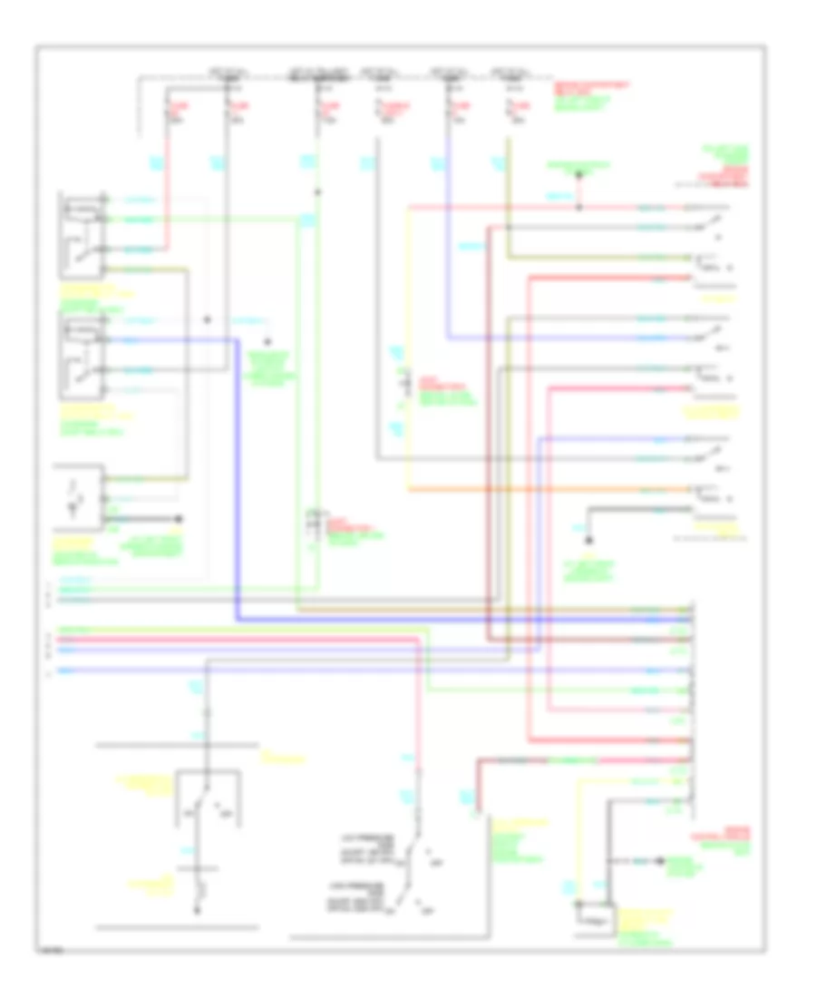
Manual A/C Wiring Diagram, Evolution (1 of 2) for Mitsubishi Lancer LS 2004
 https://portal-diagnostov.com/license.html
Automotive Electricians Portal FZCO
Automotive Electricians Portal FZCO
https://portal-diagnostov.com/license.html
https://portal-diagnostov.com/license.html
Automotive Electricians Portal FZCO
Automotive Electricians Portal FZCO
List of elements for Manual A/C Wiring Diagram, Evolution (1 of 2) for Mitsubishi Lancer LS 2004:
- (behind instrument cluster)
- A/c ecu
- A/c switch, outside/inside air selection damper control & illumination
- A17
- A17-1
- Air thermo sensor (behind right center of of dash, on hvac unit)
- Blower motor (behind right end of dash)
- Blower relay
- Blower switch
- C210
- C211
- C214
- Cooling fan motor
- Defogger system
- Fan control module (on fan shroud, at left front of engine compt)
- Fuse 30a
- Fuse 7.5a
- G13 (at left front corner of engine compartment)
- G3 (at right side of front deck crossmember)
- G6 (behind center of dash, near left center reinforcement)
- G7 (at top left side of dash)
- Hot at all times
- Hot in on
- Inlet side
- Interior lights system
- Joint connector 2
- Joint connector 3 (behind right side of dash)
- Junction block (behind left end of dash)
- Nca
- Off
- Outlet side
- Outside/inside air selection damper control motor (behind upper right end of dash)
- Pnk
- Resistor (behind right side of dash, on hvac unit)
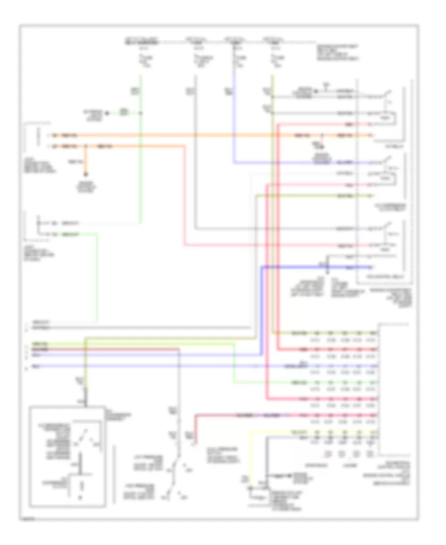
Manual A/C Wiring Diagram, Evolution (2 of 2) for Mitsubishi Lancer LS 2004
List of elements for Manual A/C Wiring Diagram, Evolution (2 of 2) for Mitsubishi Lancer LS 2004:
- (on engine compt relay box)
- (on left side of engine compt) engine compartment relay box
- A/c compressor
- A/c compressor clutch
- A/c compressor control relay
- A/c refrigerant temperature switch
- A34
- A35
- C115
- C119
- C121
- Condenser fan control relay (high) (on engine compt relay box)
- Condenser fan control relay (low)
- Condenser fan motor (mounted on rear of radiator)
- Dual pressure switch (on right side of engine compartment)
- Engine compartment relay box (on left side of engine compt)
- Engine control module (behind glove box)
- Engine controls system
- Engine coolant temperature sensor (on rear of cylinder head)
- Fan control relay
- Fuse 10a
- Fuse 20a
- Fuse 30a
- Fuse 7.5a
- Fusible link 2 50a
- G13 (at left front corner of engine compartment)
- G13 (at left front corner of engine compt)
- Headlights, exterior lights & wiper/washer systems
- High pressure side on-off: 2940 kpa off-on: 2350 kpa
- Hot at all times
- Hot w/ taillight relay energized
- Joint connector 1 (behind center of dash)
- Joint connector 6 (behind lower center of dash)
- Low pressure side on-off: 196 kpa off-on: 221 kpa
- Mfi relay
- Nca
- Off
- Pnk
- Red
Manual A/C Wiring Diagram, Except Evolution (1 of 2) for Mitsubishi Lancer LS 2004
List of elements for Manual A/C Wiring Diagram, Except Evolution (1 of 2) for Mitsubishi Lancer LS 2004:
- (behind instrument cluster)
- A/c ecu (behind center of dash, below radio)
- A17
- A17-1
- A17-2
- A18
- A18-1
- A18-2
- Air thermo sensor (behind right center of of dash, on hvac unit)
- Blower motor (behind right end of dash)
- Blower relay
- Blower switch
- C210 c211
- C211 c212
- C214 c215
- Condenser fan motor (mounted on rear of radiator)
- Defogger system
- Fan control module (on fan shroud, at left front of engine compartment)
- Fuse 30a
- Fuse 7.5a
- G12 (sportback) (at left front of engine compartment, left of battery)
- G13 (lancer) (at left front corner of engine compartment)
- G3 (under right front kick panel)
- G5 (sportback) (on center tunnel, right of accelerator pedal)
- G6 (lancer) (behind center of dash, near left center reinforcement)
- Heater control panel & illumination
- Hot at all times
- Hot in on
- Inlet side
- Interior lights system
- Joint connector 2
- Joint connector 3 (behind right side of dash)
- Junction block (behind left end of dash)
- Lancer
- Lancer sportback
- Nca
- Off
- Outlet side
- Outside/inside air selection damper control motor (behind upper right end of dash)
- Radiator fan motor
- Resistor (behind right side of dash, on hvac unit)
- Sportback
Manual A/C Wiring Diagram, Except Evolution (2 of 2) for Mitsubishi Lancer LS 2004
List of elements for Manual A/C Wiring Diagram, Except Evolution (2 of 2) for Mitsubishi Lancer LS 2004:
- 2.0l a/t
- 2.0l m/t
- 2.4l
- 2.4l a/t
- 2.4l m/t
- A/c compressor assembly
- A/c compressor clutch
- A/c compressor clutch relay
- A/c refrigerant temperature switch (on-off: 150 degrees centigrade) (off-on: 120 degrees centigrade)
- C111
- C112
- C113
- C114
- C115
- C116
- C118
- C119
- C120
- C121
- C133
- C134
- C135
- C136
- C137
- C138
- C139
- C140
- Dual pressure switch (on right front of engine compt)
- Engine compartment relay box (on left side of engine compartment)
- Engine compartment relay box (on left side of engine compt)
- Engine controls system
- Engine coolant temperature sensor (on rear of cylinder head)
- Exterior lights system
- Fan control relay
- Fuse 10a
- Fuse 20a
- Fuse 7.5a
- Fusible link 2 50a
- G12 (sportback) (at left front of engine compt, left of battery)
- G13 (lancer) (at left front corner of engine compt)
- High pressure side on-off: 3138 kpa off-on: 2550 kpa
- Hot at all times
- Hot w/ taillight relay energized
- Joint connector 1 (behind center of dash)
- Joint connector 6 (behind lower center of dash)
- Lancer
- Low pressure side on-off: 196 kpa off-on: 221 kpa
- Mfi relay
- Nca
- Off
- Pnk
- Powertrain control module (a/t) engine control module (m/t) (behind glove box)
- Red
- Sportback

 Čeština
 Dansk
Dansk Deutsch
 Ελληνικά
 English
 Español
 Suomi
Suomi Français
 Français
 עברית
עברית Hrvatski
 Magyar
 Italiano
 日本語
日本語 한국어
한국어 Nederlands
 Polski
 Português
 Português
 Română
 Русский
 Slovenčina
 Slovenščina
 Svenska
 Türkçe
 中文 (中国)