AIR CONDITIONING
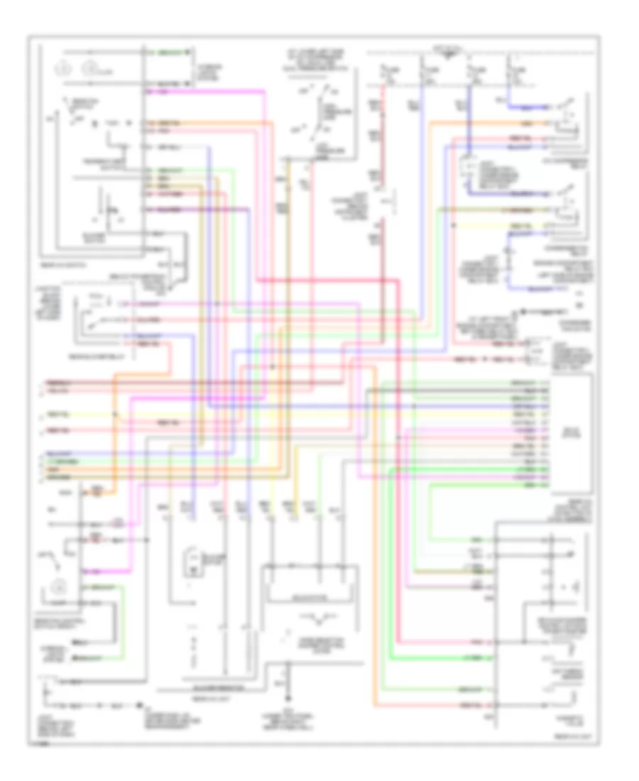
Automatic A/C Wiring Diagram, with Rear A/C (1 of 2) for Mitsubishi Montero Limited 2003
 https://portal-diagnostov.com/license.html
Automotive Electricians Portal FZCO
Automotive Electricians Portal FZCO
https://portal-diagnostov.com/license.html
https://portal-diagnostov.com/license.html
Automotive Electricians Portal FZCO
Automotive Electricians Portal FZCO
List of elements for Automatic A/C Wiring Diagram, with Rear A/C (1 of 2) for Mitsubishi Montero Limited 2003:
- A/c compressor
- A/c ecu (behind center of dash)
- Air conditioning sensor (on hvac assembly)
- Air mixing damper control motor & potentiometer
- Blower motor
- D08
- D132
- D134
- D208
- D209
- D210
- D220
- D23
- D24
- Data link connector (lower left side
- Defogger system
- Front blower relay
- Fuse 10a
- Fuse 15a
- Fuse 30a
- G7 (under dash, on driver side center reinforcement)
- G8 (under dash, on passenger side reinforcement)
- Heater blower controller unit (on hvac assembly)
- Heater water temperature sensor (on hvac assembly)
- Hot at all times
- Hot in acc
- Hot in on
- Interior lights system
- Joint connector 5 (behind left side of dash)
- Joint connector 6 (behind instrument cluster)
- Joint connector 8 (behind left side of dash)
- Junction block (behind lower left side of dash)
- Lock sensor
- Magnetic clutch
- Mode selection damper control motor & potentiometer
- Of dash, right of steering column)
- Outside air temperature sensor (at lower right front of a/c condenser)
- Outside/ inside air selection damper control motor
- Photo sensor (on top center of dash)
- Pnk
- Powertrain control module (behind lower right side of dash)
- Red
- Rv meter
- Solid state
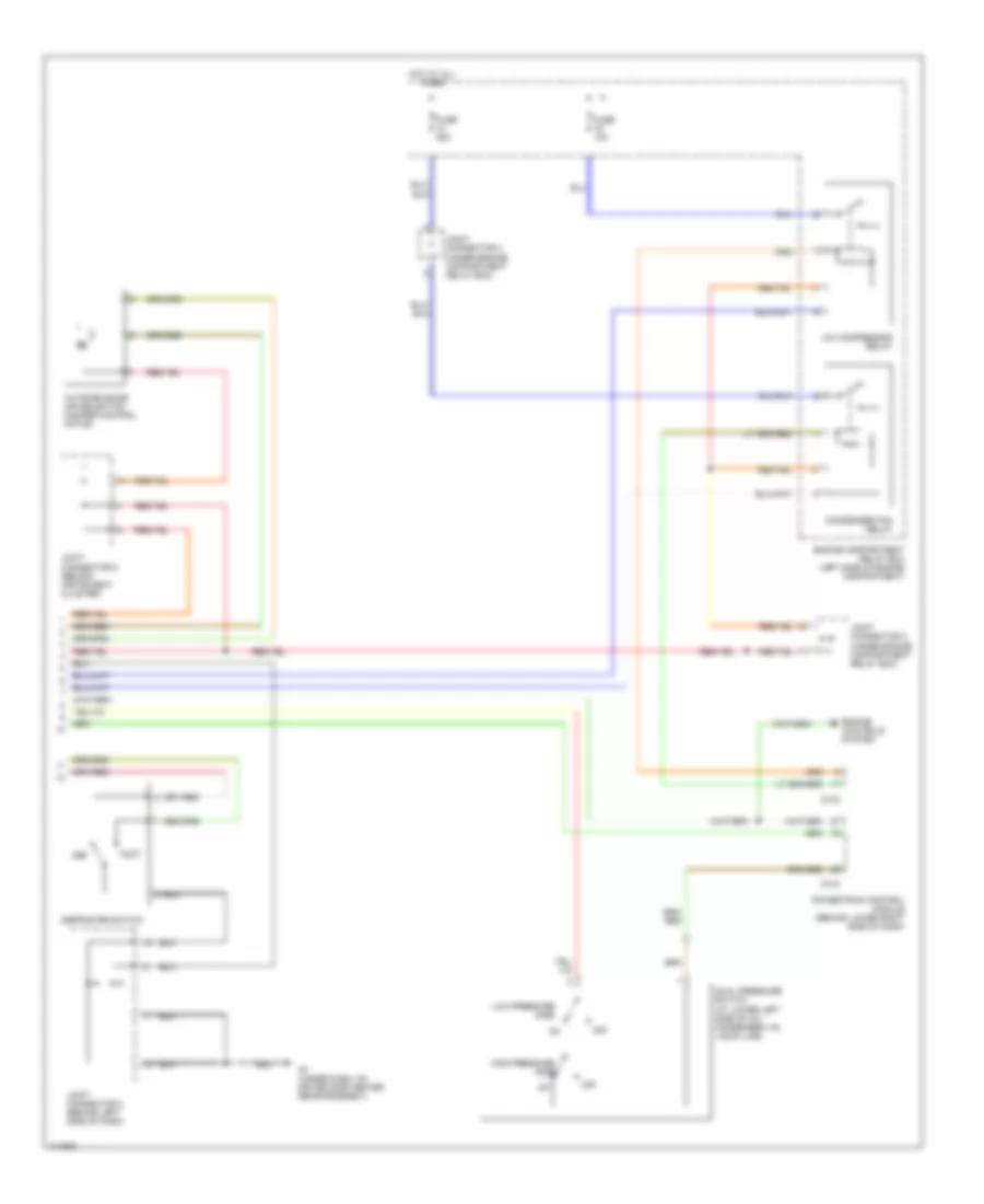
Automatic A/C Wiring Diagram, with Rear A/C (2 of 2) for Mitsubishi Montero Limited 2003
List of elements for Automatic A/C Wiring Diagram, with Rear A/C (2 of 2) for Mitsubishi Montero Limited 2003:
- (at lower left side of a/c compressor, on liquid line) dual pressure switch
- (below powertrain control module) g12
- A/c compressor relay
- Air mixing damper control motor & potentiometer
- Air thermo sensor
- Blower motor
- Blower resistor
- Blower switch
- Condenser fan motor
- Condenser fan relay
- Engine compartment relay box (left side of engine compartment)
- Fuse 10a
- Fuse 20a
- Fuse 25a
- G15 (under trim panel, behind right rear wheelwell)
- G24
- G26
- G6 (at left front of engine compartment, between relay box & fender panel)
- G7 (under dash, on driver side center reinforcement)
- High- pressure side
- Hot at all times
- Illum
- Interior lights system
- Joint connector 1 (under engine compartment relay box)
- Joint connector 2 (under engine compartment relay box)
- Joint connector 3 (under engine compartment relay box)
- Joint connector 7 (behind instrument cluster)
- Joint connector 8 (behind left side of dash)
- Junction block (behind lower left side of dash)
- Low- pressure side
- Magnetic valve
- Mode selection damper control motor
- Off
- Pnk
- Rear a/c control unit (on bottom of hvac assembly)
- Rear a/c switch
- Rear a/c unit
- Rear blower relay
- Rear fan control switch (front)
- Rear fan switch
- Solid state
- Temperature switch
Automatic A/C Wiring Diagram, with Rear Cooler (1 of 2) for Mitsubishi Montero Limited 2003
List of elements for Automatic A/C Wiring Diagram, with Rear Cooler (1 of 2) for Mitsubishi Montero Limited 2003:
- A/c compressor
- A/c ecu (behind center of dash)
- Air conditioning sensor (on hvac assembly)
- Air mixing damper control motor & potentiometer
- Blower motor
- Connector (lower left side of dash, right of steering column)
- D08
- D132
- D134
- D208
- D209
- D210
- D220
- D23
- D24
- Data link
- Defogger system
- Front blower relay
- Fuse 10a
- Fuse 15a
- Fuse 30a
- G7 (under dash, on driver side center reinforcement)
- G8 (under dash, on passenger side reinforcement)
- Gnd
- Heater blower controller unit (on hvac assembly)
- Heater water temperature sensor (on hvac assembly)
- Hot at all times
- Hot in acc
- Hot in on
- Interior lights system
- Joint connector 5 (behind left side of dash)
- Joint connector 6 (behind instrument cluster)
- Joint connector 8 (behind left side of dash)
- Junction block (behind lower left side of dash)
- Lock sensor
- Magnetic clutch
- Mode selection damper control motor & potentiometer
- Outside air temperature sensor (at lower right front of a/c condenser)
- Outside/inside air selection damper control motor
- Photo sensor (on top center of dash)
- Pnk
- Power
- Powertrain control module (behind lower right side of dash)
- Red
- Rv meter
- Solid state
Automatic A/C Wiring Diagram, with Rear Cooler (2 of 2) for Mitsubishi Montero Limited 2003
List of elements for Automatic A/C Wiring Diagram, with Rear Cooler (2 of 2) for Mitsubishi Montero Limited 2003:
- (under right front kick panel, below powertrain control module)
- A/c compressor relay
- Air conditioning sensor
- Blower motor
- Blower resistor
- Blower switch
- Condenser fan motor
- Condenser fan relay
- Dual pressure switch (at lower left side of a/c condenser, on liquid line)
- Engine compartment relay box (left side of engine compartment)
- Fuse 10a
- Fuse 20a
- Fuse 25a
- G12
- G6 (at left front of engine compartment, between relay box & fender panel)
- G7 (under dash, on driver side center reinforcement)
- Gnd
- High-pressure side
- Hot at all times
- Illum
- Interior lights system
- Joint connector 1 (under engine compartment relay box)
- Joint connector 2 (under engine compartment relay box)
- Joint connector 3 (under engine compartment relay box)
- Joint connector 7 (behind instrument cluster)
- Joint connector 8 (behind left side of dash)
- Junction block (behind lower left side of dash)
- Low-pressure side
- Magnetic valve
- Off
- Pnk
- Power
- Rear blower relay
- Rear blower unit
- Rear cooler control unit (on bottom of hvac assembly)
- Rear cooler switch
- Rear cooler unit
- Rear fan control switch (front)
- Solid state
- Temperature switch
Manual A/C Wiring Diagram, Dual A/C Wiring Diagram with Rear A/C (1 of 2) for Mitsubishi Montero Limited 2003
List of elements for Manual A/C Wiring Diagram, Dual A/C Wiring Diagram with Rear A/C (1 of 2) for Mitsubishi Montero Limited 2003:
- (at lower left side of a/c condenser, on liquid line) dual pressure switch
- A/c compressor
- A/c switch
- Air conditioning sensor (on hvac assembly)
- Automatic compressor controller (behind lower left side of dash, right of steering column)
- Blower motor
- Blower resistor
- Blower switch
- D119
- D120
- D132
- D134
- D208
- D209
- D210
- Def
- Defogger system
- Defroster switch
- Engine controls system
- Foot
- Front blower relay
- Fuse 10a
- Fuse 30a
- G7 (under dash, on driver side center reinforcement)
- G7 (under dash, on driver side center reinforcement)
- G8 (under dash, on passenger side reinforcement)
- Gnd
- Heater control panel illumination light
- High-pressure side
- Hot at all times
- Hot in on
- Illum
- Ind
- Inside air
- Interior lights system
- Joint connector (behind left side of dash)
- Joint connector 5 (behind left side of dash)
- Joint connector 6 (behind instrument cluster)
- Joint connector 8 (behind left side of dash)
- Junction block (behind lower left side of dash)
- Lock sensor
- Low-pressure side
- Magnetic clutch
- Off
- Outside air
- Outside/inside air selection damper control motor
- Outside/inside air selection switch
- Powertrain control module (behind lower right side of dash)
Manual A/C Wiring Diagram, Dual A/C Wiring Diagram with Rear A/C (2 of 2) for Mitsubishi Montero Limited 2003
List of elements for Manual A/C Wiring Diagram, Dual A/C Wiring Diagram with Rear A/C (2 of 2) for Mitsubishi Montero Limited 2003:
- (under right front kick panel, below powertrain control module)
- (under trim panel, behind right rear wheelwell) g15
- A/c compressor relay
- Air conditioning sensor
- Air mixing damper control motor and potentiometer
- Blower motor
- Blower resistor
- Blower switch
- Condenser fan motor
- Condenser fan relay
- Engine compartment relay box (left side of engine compartment)
- Fuse 10a
- Fuse 20a
- Fuse 25a
- G12
- G22
- G24
- G26
- G6 (at left front of engine compartment, between relay box & fender panel)
- Gnd
- Hot at all times
- Illum
- Interior lights system
- Joint connector 1 (under engine compartment relay box)
- Joint connector 2 (under engine compartment relay box)
- Joint connector 3 (under engine compartment relay box)
- Magnetic valve
- Mode selection damper control motor
- Motor
- Motor drive circuit
- Off
- Pnk
- Pwr
- Rear a/c
- Rear a/c control unit (on bottom of hvac assembly)
- Rear a/c switch
- Rear blower relay
- Rear fan control switch (front)
- Rear fan switch
- Sig
- Temperature switch
- Unit
Manual A/C Wiring Diagram, Dual A/C Wiring Diagram with Rear Cooler (1 of 2) for Mitsubishi Montero Limited 2003
List of elements for Manual A/C Wiring Diagram, Dual A/C Wiring Diagram with Rear Cooler (1 of 2) for Mitsubishi Montero Limited 2003:
- (at lower left side of a/c condenser, on liquid line) dual pressure switch
- (behind left side of dash)
- (under dash, on passenger side reinforcement) g8
- A/c compressor
- A/c switch
- Air conditioning sensor (on hvac assembly)
- Automatic compressor controller (behind lower left side of dash, right of steering column)
- Blower motor
- Blower resistor
- Blower switch
- D119
- D120
- D132
- D134
- D208
- D209
- D210
- Def
- Defogger system
- Defroster switch
- Engine controls system
- Foot
- Front blower relay
- Fuse 10a
- Fuse 30a
- G7 (under dash, on driver side center reinforcement)
- Gnd
- Heater control panel illumination light
- High- pressure side
- Hot at all times
- Hot in on
- Illum
- Ind
- Inside air
- Interior lights system
- Joint connector
- Joint connector 5 (behind left side of dash)
- Joint connector 6 (behind instrument cluster)
- Joint connector 8 (behind left side of dash)
- Junction block (behind lower left side of dash)
- Lock sensor
- Low- pressure side
- Magnetic clutch
- Off
- Outside air
- Outside/inside air selection damper control motor
- Outside/inside air selection switch
- Powertrain control module (behind lower right side of dash)
- Pwr source
Manual A/C Wiring Diagram, Dual A/C Wiring Diagram with Rear Cooler (2 of 2) for Mitsubishi Montero Limited 2003
List of elements for Manual A/C Wiring Diagram, Dual A/C Wiring Diagram with Rear Cooler (2 of 2) for Mitsubishi Montero Limited 2003:
- A/c compressor relay
- Air conditioning sensor
- Blower motor
- Blower resistor
- Blower switch
- Condenser fan motor
- Condenser fan relay
- Engine compartment relay box (left side of engine compartment)
- Fuse 10a
- Fuse 20a
- Fuse 25a
- G12 (under right front kick panel, below powertrain control module)
- G6 (at left front of engine compartment, between relay box & fender panel)
- Gnd
- Hot at all times
- Illum
- Interior lights system
- Joint connector 1 (under engine compartment relay box)
- Joint connector 2 (under engine compartment relay box)
- Joint connector 3 (under engine compartment relay box)
- Junction block (behind lower left side of dash)
- Magnetic valve
- Off
- Pnk
- Pwr source
- Rear blower relay
- Rear blower unit
- Rear cooler control unit (on bottom of hvac assembly)
- Rear cooler switch
- Rear cooler unit
- Rear fan control switch (front)
- Rear fan switch
- Temperature switch
Manual A/C Wiring Diagram, Dual A/C Wiring Diagram with Rear Heater (1 of 2) for Mitsubishi Montero Limited 2003
List of elements for Manual A/C Wiring Diagram, Dual A/C Wiring Diagram with Rear Heater (1 of 2) for Mitsubishi Montero Limited 2003:
- (at lower left side of a/c condenser, on liquid line) dual pressure switch
- (behind left side of dash)
- A/c compressor
- A/c switch
- Air conditioning sensor (on hvac assembly)
- Automatic compressor controller (behind lower left side of dash, right of steering column)
- Blower motor
- Blower resistor
- Blower switch
- D119
- D120
- D132
- D134
- D208
- D209
- D210
- Def
- Defogger system
- Defroster switch
- Engine controls system
- Foot
- Front blower relay
- Fuse 10a
- Fuse 30a
- G7 (under dash, on driver side center reinforcement)
- G8 (under dash, on passenger side reinforcement)
- Gnd
- Heater control panel illumination light
- High-pressure side
- Hot at all times
- Hot in on
- Illum
- Ind
- Inside air
- Interior lights system
- Joint connector
- Joint connector 5 (behind left side of dash)
- Joint connector 6 (behind instrument cluster)
- Joint connector 8 (behind left side of dash)
- Junction block (behind lower left side of dash)
- Lock sensor
- Low-pressure side
- Magnetic clutch
- Off
- Outside air
- Outside/inside air selection damper control motor
- Outside/inside air selection switch
- Powertrain control module (behind lower right side of dash)
- Pwr source
Manual A/C Wiring Diagram, Dual A/C Wiring Diagram with Rear Heater (2 of 2) for Mitsubishi Montero Limited 2003
List of elements for Manual A/C Wiring Diagram, Dual A/C Wiring Diagram with Rear Heater (2 of 2) for Mitsubishi Montero Limited 2003:
- A/c compressor relay
- Air mixing damper control motor & potentiometer
- Blower motor
- Blower resistor
- Blower switch
- Condenser fan motor
- Condenser fan relay
- Engine compartment relay box (left side of engine compartment)
- Fuse 10a
- Fuse 20a
- Fuse 25a
- G12 (under right front kick panel, below powertrain control module)
- G23
- G25
- G6 (at left front of engine compartment, between relay box & fender panel)
- Gnd
- Hot at all times
- Illum
- Interior lights system
- Joint connector 1 (under engine compartment relay box)
- Joint connector 2 (under engine compartment relay box)
- Joint connector 3 (under engine compartment relay box)
- Junction block (behind lower left side of dash)
- Motor
- Off
- Pnk
- Pwr source
- Rear blower relay
- Rear blower unit
- Rear fan control switch (front)
- Rear fan switch
- Rear heater control unit (on bottom of hvac assembly)
- Rear heater switch
- Rear heater unit
- Signal
- Temperature switch
Manual A/C Wiring Diagram, Single A/C Wiring Diagram (1 of 2) for Mitsubishi Montero Limited 2003
List of elements for Manual A/C Wiring Diagram, Single A/C Wiring Diagram (1 of 2) for Mitsubishi Montero Limited 2003:
- A/c compressor
- A/c switch
- Air conditioning sensor (on hvac assembly)
- Automatic compressor controller (behind lower left side of dash, right of steering column)
- Blower motor
- Blower resistor
- Blower switch
- Condenser fan motor
- D119
- D120
- D208
- D209
- D210
- Defogger system
- Front blower relay
- Fuse 10a
- Fuse 30a
- G6 (at left front of engine compartment, between relay box & fender panel)
- G7 (under dash, on driver side center reinforcement)
- G8 (under dash, on passenger side reinforcement)
- Gnd
- Heater control panel illumination light
- Hot at all times
- Hot in on
- Illum
- Ind
- Inside air
- Interior lights system
- Joint connector 1 (under engine compt relay box)
- Joint connector 3 (under engine compartment relay box)
- Joint connector 5 (behind left side of dash)
- Joint connector 8 (behind left side of dash)
- Junction block (behind lower left side of dash)
- Lock sensor
- Magnetic clutch
- Off
- Outside air
- Outside/inside air selection switch
- Pwr source
Manual A/C Wiring Diagram, Single A/C Wiring Diagram (2 of 2) for Mitsubishi Montero Limited 2003
List of elements for Manual A/C Wiring Diagram, Single A/C Wiring Diagram (2 of 2) for Mitsubishi Montero Limited 2003:
- A/c compressor relay
- Condenser fan relay
- D132
- D134
- Def
- Defroster switch
- Dual pressure switch (at lower left side of a/c condenser, on liquid line)
- Engine compartment relay box (left side of engine compartment)
- Engine controls system
- Foot
- Fuse 10a
- Fuse 25a
- G7 (under dash, on driver side center reinforcement)
- High-pressure side
- Hot at all times
- Joint connector 2 (under engine compartment relay box)
- Joint connector 3 (under engine compartment relay box)
- Joint connector 6 (behind instrument cluster)
- Joint connector 8 (behind left side of dash)
- Low-pressure side
- Off
- Outside/inside air selection damper control motor
- Powertrain control module (behind lower right side of dash)

 Čeština
 Dansk
Dansk Deutsch
 Ελληνικά
 English
 Español
 Suomi
Suomi Français
 Français
 עברית
עברית Hrvatski
 Magyar
 Italiano
 日本語
日本語 한국어
한국어 Nederlands
 Polski
 Português
 Português
 Română
 Русский
 Slovenčina
 Slovenščina
 Svenska
 Türkçe
 中文 (中国)