AIR CONDITIONING
Heater Wiring Diagram for Nissan Altima GXE 1999
 https://portal-diagnostov.com/license.html
Automotive Electricians Portal FZCO
Automotive Electricians Portal FZCO
https://portal-diagnostov.com/license.html
https://portal-diagnostov.com/license.html
Automotive Electricians Portal FZCO
Automotive Electricians Portal FZCO
List of elements for Heater Wiring Diagram for Nissan Altima GXE 1999:
- Blower motor (behind right side of dash, on hvac housing)
- Fan resistor (on right side of hvac housing, near blower motor)
- Fan switch
- Fuse 15a
- Fuse block (under left side of dash)
- G200 (left kick panel)
- G203 (right kick panel)
- Hot in on
- Off
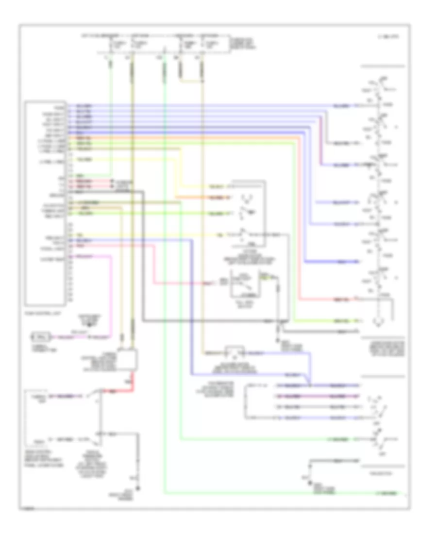
Manual A/C Wiring Diagram (1 of 2) for Nissan Altima GXE 1999
List of elements for Manual A/C Wiring Diagram (1 of 2) for Nissan Altima GXE 1999:
- (+) face, (-) def
- (+) fre, (-) rec
- (-) face, (+) def
- (-) fre, (+) rec
- (on right side of hvac housing, near blower motor)
- 10s
- 1994 vftc c
- 3m 3m
- A/c switch
- B/l
- B/l input
- Blower motor (behind right side of dash, on hvac housing)
- Cool position
- Def
- Def input
- Eccs control module (ecm) (behind instrument
- F/cool, m/sw
- F/d
- F/d input
- Face
- Face input
- Fan hi
- Fan resistor
- Fan switch
- Foot
- Foot input
- Fre
- Fre input
- Full cool switch
- Fuse 1 fuse 1 15a 15a
- Fuse 2 15a
- Fuse 6 10a
- Fuse 8 10a
- Fuse block (under left side of dash)
- G101 (right front fender)
- G203 (right side kick panel)
- Ground
- Hot in on
- Hot in on, or start
- Ign
- Ill
- Instrument cluster system
- Intake door motor (behind right side of dash, left of blower motor)
- Interior lights system
- Mode door motor (behind center of dash, on left end of hvac housing)
- Off
- Others
- Panel lower cover)
- Pnk
- Psdw
- Push control unit
- Rec
- Rec input
- Red
- Thermal transmitter
- Thermo amp
- Thermo control amplifier (behind right side of dash, on hvac housing)
- Triple pressure switch (at left front of engine compt, on a/c system liquid tank)
- Water temp
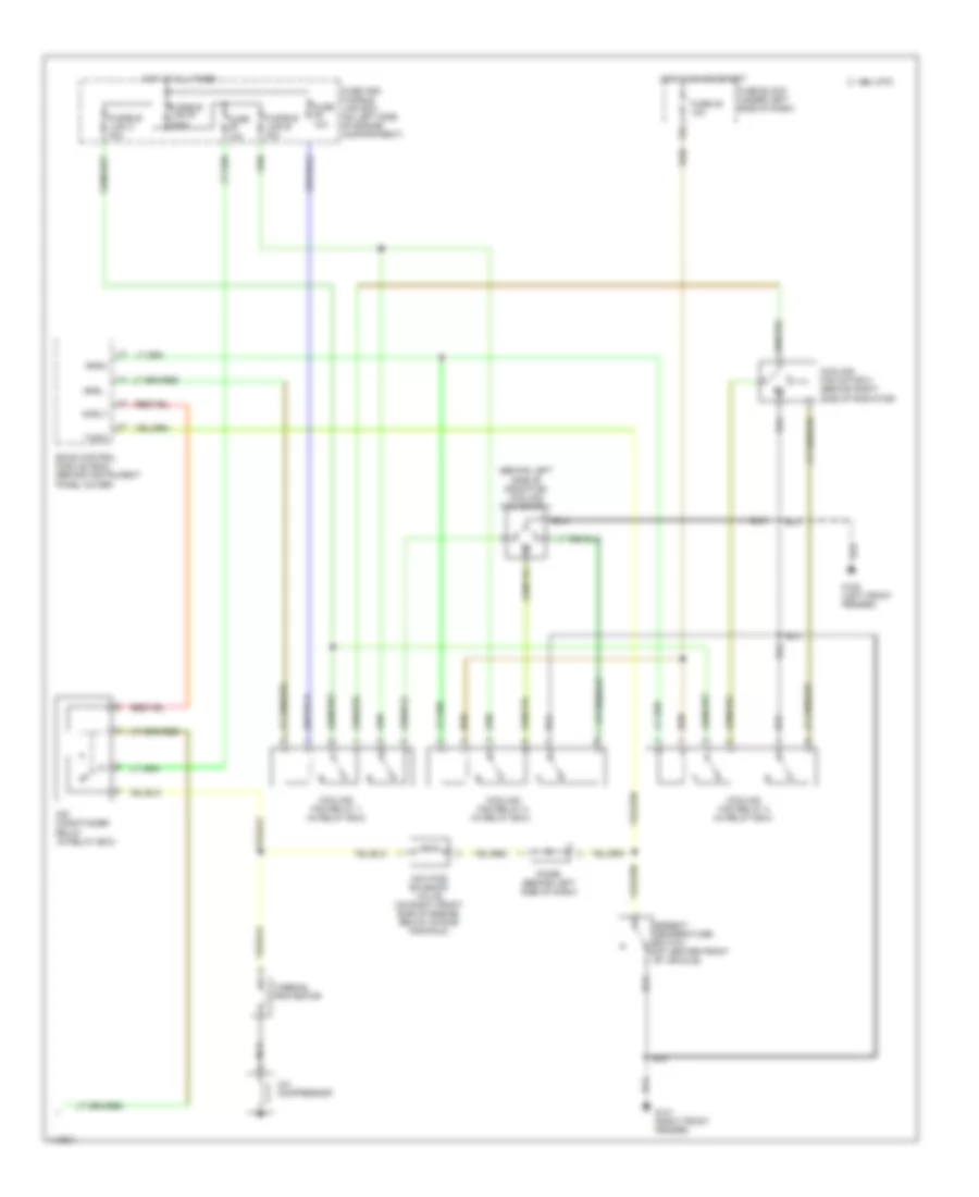
Manual A/C Wiring Diagram (2 of 2) for Nissan Altima GXE 1999
List of elements for Manual A/C Wiring Diagram (2 of 2) for Nissan Altima GXE 1999:
- (behind left side of radiator) cooling fan motor 1
- 1994 vftc c
- A/c compressor
- Acrly
- Air conditioner relay (in relay box)
- Ambient temperature switch (at center front of vehicle)
- Cooling fan motor 2 (behind right side of radiator)
- Cooling fan relay 1 (in relay box)
- Cooling fan relay 2 (in relay box)
- Cooling fan relay 3 (in relay box)
- Diode (behind left side of dash)
- Eccs control module (ecm) (behind instrument panel cover)
- Fuse 10a
- Fuse 25 10a
- Fuse and fusible link box (on left side of engine compartment)
- Fuse block (under left side of dash)
- Fusible link b 40a
- Fusible link c 40a
- Fusible link e 100a
- G100 (left front fender)
- G101 (right front fender)
- Hot at all times
- Hot in on and start
- Iacv-ficd solenoid valve (on right front side of engine, below intake manifold)
- Nca
- Rfrh
- Rfrl
- Tasw
- Thermal protector

 Čeština
 Dansk
Dansk Deutsch
 Ελληνικά
 English
 Español
 Suomi
Suomi Français
 Français
 עברית
עברית Hrvatski
 Magyar
 Italiano
 日本語
日本語 한국어
한국어 Nederlands
 Polski
 Português
 Português
 Română
 Русский
 Slovenčina
 Slovenščina
 Svenska
 Türkçe
 中文 (中国)