AIR CONDITIONING
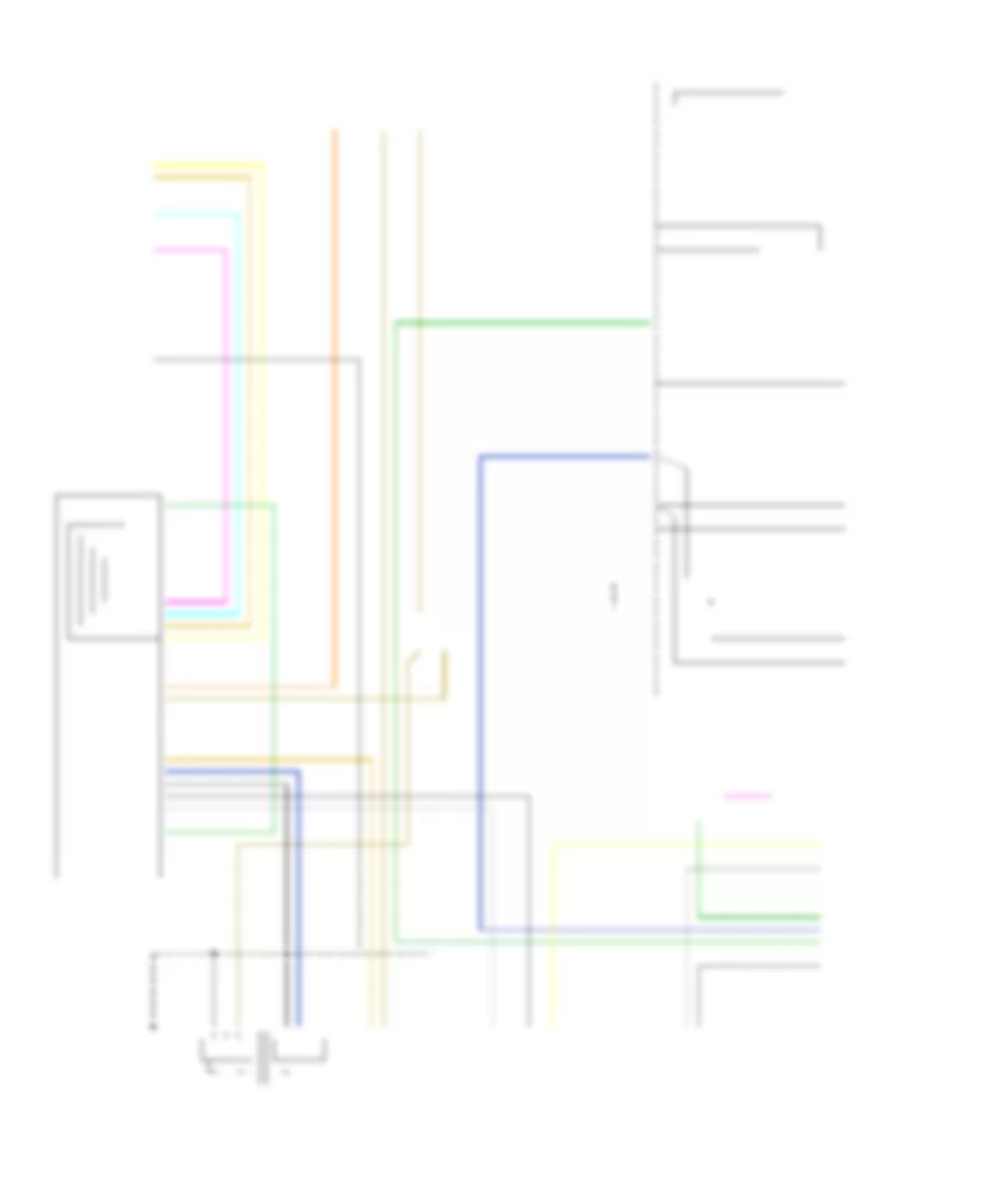
Compressor Wiring Diagram for Pontiac Aztek GT 2001
 https://portal-diagnostov.com/license.html
Automotive Electricians Portal FZCO
Automotive Electricians Portal FZCO
https://portal-diagnostov.com/license.html
https://portal-diagnostov.com/license.html
Automotive Electricians Portal FZCO
Automotive Electricians Portal FZCO
List of elements for Compressor Wiring Diagram for Pontiac Aztek GT 2001:
- +5v reference
- A/c compressor clutch
- A/c clu fuse 10a
- A/c compressor clutch relay
- A/c compressor diode
- A/c press sig
- A/c refrigerent pressure sensor (left side of engine compt, on accumulator)
- A/c request
- A10
- B10
- Battery
- Body control module (attached to console wiring j/b)
- Comp control
- Console accessory wiring junction block
- Datalink connector (below steering column)
- G114 (left rear of engine)
- G201 (behind right side of dash)
- Ground
- Hot at all times
- Hot in run or start
- Hvac control assembly
- Ign 1 main relay (closed in run or start)
- Ign hvac fuse 10a
- Ignition
- Ip misc fuse 10a c1
- Low reference
- Powertrain control module (left side of engine compartment, in air cleaner assembly)
- Resistor breakout)
- Serial data
- Splice pack sp250
- Star connector (behind dash)
- Underhood fuse block (right side of engine compt, above battery)
Manual A/C Wiring Diagram for Pontiac Aztek GT 2001
List of elements for Manual A/C Wiring Diagram for Pontiac Aztek GT 2001:
- (dash harn, 4 cm from blwr motor resistor breakout) s213
- (fuel inj harn, top center of engine)
- (fwd lamp harn, 5 cm from horn breakout)
- +5v reference
- A/c compressor clutch
- A/c clu fuse 10a
- A/c compressor clutch relay
- A/c compressor diode
- A/c press signal
- A/c refrigerent pressure sensor (left side
- A/c request
- A/c request sig
- A10
- B10
- Battery
- Blower motor
- Blower motor relay
- Blower motor resistor assembly
- Blower sw off
- Body control module (attached to console wiring j/b)
- Breakout)
- C11
- Comp control
- Console accessory wiring junction block
- Cool fan 1 fuse 30a
- Cool fan 1 relay
- Cool fan 2 fuse 30a
- Cool fan 2 relay
- Cool fan 3 relay
- Coolant fan 1
- Coolant fan 2
- Datalink connector (below steering column)
- Defogger
- Ect sensor
- Engine controls sensor (map sensor)
- Engine coolant temperature (ect) sensor (top rear of engine, near thermostat housing)
- Engine cooling fan (left)
- Engine cooling fan (right)
- F10
- Frost sens +
- Frost sens rtn
- Frost sensor (in hvac assembly, on evap coil)
- Frt blwr fuse 25a
- G103 (right side of engine compt)
- G114 (left rear of engine)
- G201 (behind right side of dash)
- Ground
- Hot at all times
- Hot in run
- Hot in run or start
- Hvac control assembly
- Ign 1 main relay (closed in run or start)
- Ign 3 fuse 40a
- Ign hvac fuse 10a c1
- Ignition
- Interior lights
- Ip misc fuse 10a
- Lamp dim sig
- Left air temp act
- Left air temperature motor (left side of hvac assembly)
- Low reference
- Mode door ctrl
- Mode motor (left side of hvac assembly)
- Of engine compt, on accumulator)
- Off
- Powertrain control module (left side of engine compartment, in air cleaner assembly)
- Rear defog
- Recir/osa motor (right end of hvac assembly)
- Recirc door ctrl
- Red
- Right air temp act
- Right air temperature mptpr (left side of hvac assembly
- S105
- S110
- S123
- Serial data
- Splice pack sp250
- Star connector (behind dash)
- Tan
- Underhood fuse block (right side of engine compt, above battery)

 Čeština
 Dansk
Dansk Deutsch
 Ελληνικά
 English
 Español
 Suomi
Suomi Français
 Français
 עברית
עברית Hrvatski
 Magyar
 Italiano
 日本語
日本語 한국어
한국어 Nederlands
 Polski
 Português
 Português
 Română
 Русский
 Slovenčina
 Slovenščina
 Svenska
 Türkçe
 中文 (中国)