AIR CONDITIONING
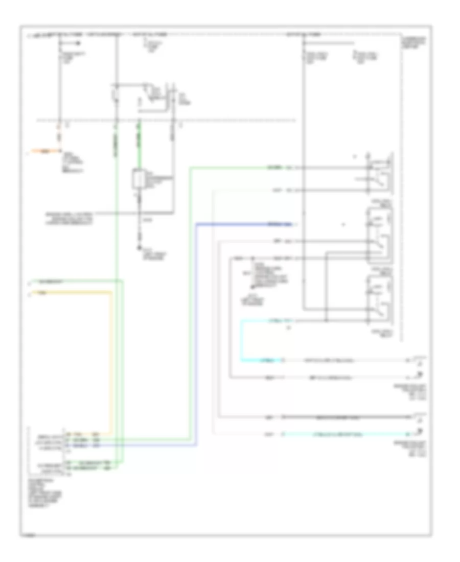
Automatic A/C Wiring Diagram (1 of 2) for Pontiac Grand Prix GTP 1999
 https://portal-diagnostov.com/license.html
Automotive Electricians Portal FZCO
Automotive Electricians Portal FZCO
https://portal-diagnostov.com/license.html
https://portal-diagnostov.com/license.html
Automotive Electricians Portal FZCO
Automotive Electricians Portal FZCO
List of elements for Automatic A/C Wiring Diagram (1 of 2) for Pontiac Grand Prix GTP 1999:
- (i/p harn, 34 cm from heater-a/c control breakout)
- (i/p harn, 4 cm from i/p compt lamp switch breakout)
- (i/p harness, 4 cm from dlc breakout)
- +5 v
- A/c module)
- A/c request
- A/c sol ctrl
- A/c solenoid
- Ambient outside temperature sensor (behind front panel, mounted to radiator air baffle)
- Battery
- Bi-lev sol ctrl
- Bi-level solenoid
- Blower motor
- Blower motor resistor (in right side of heater- a/c module)
- C 1995 vftc
- C10
- C11
- C12
- C13
- C14
- C15
- C16
- Cntrl in
- D10
- D11
- D12
- D13
- D14
- D15
- D16
- Data link connector (under left side of dash, right of steering column)
- Def sol ctrl
- Defrost solenoid
- English/metric
- Fuse block
- G200 (right side of dash)
- Grd
- Ground
- Heater solenoid
- Heater-a/c control
- Hot at all times
- Hot in run
- Htr sol ctrl
- Hvac fuse 10a
- Hvac hi fuse 30a
- Ignition
- Inside air temperature sensor (right side of instrument cluster)
- Inside temp input
- Left electric actuator (left side of heater- a/c module)
- Lt elec actuator
- Motor drive
- Nca
- Outside temp input
- Recirc sol ctrl
- Recirc solenoid
- Red
- Right electric actuator (right side of heater-
- Rt elec actuator
- S211 (i/p harn 11 cm from dlc)
- S213 (i/p harn, 4 cm from blower control module breakout)
- S237 (i/p harn, 30 cm from dlc breakout)
- S245
- S258
- Sensor ground
- Serial data
- Solid state
- Spd cntrl
- Sun load input
- Sun load temperature sensor (top center of dash)
- Tan
- Vacuum/ electric solenoid (on right side of heater-a/c module)
- Volt to blw ctrl
Automatic A/C Wiring Diagram (2 of 2) for Pontiac Grand Prix GTP 1999
List of elements for Automatic A/C Wiring Diagram (2 of 2) for Pontiac Grand Prix GTP 1999:
- (engine harn, 4 cm from engine coolant fan wiring harn breakout)
- (i/p harn, 17 cm from dlc breakout)
- A/c clu diode
- A/c clu fuse 10a
- A/c clu relay
- A/c compressor clutch coil
- A/c request
- A10
- C 1995 vftc
- C10
- C11
- Comp ctrl
- Cool fan 1 maxi fuse 30a
- Cool fan 1 relay
- Cool fan 2 maxi fuse 30a
- Cool fan 2 relay
- Cool fan 3 relay
- Engine coolant fan motor 1 (lh - 3.1l) (rh - 3.8l)
- Engine coolant fan motor 2 (rh - 3.1l) (lh - 3.8l)
- F11
- G117 (left front of engine)
- Hi spd ctrl
- Hot at all times
- Hot in on or run
- Low spd ctrl
- Powertrain control module (left front side of engine compt, in air cleaner assembly)
- Radio batt fuse 10a
- S105
- S105 (engine harn, 4 cm from engine coolant fan wiring harn breakout)
- S202
- Serial data
- Tan
- Underhood electrical center
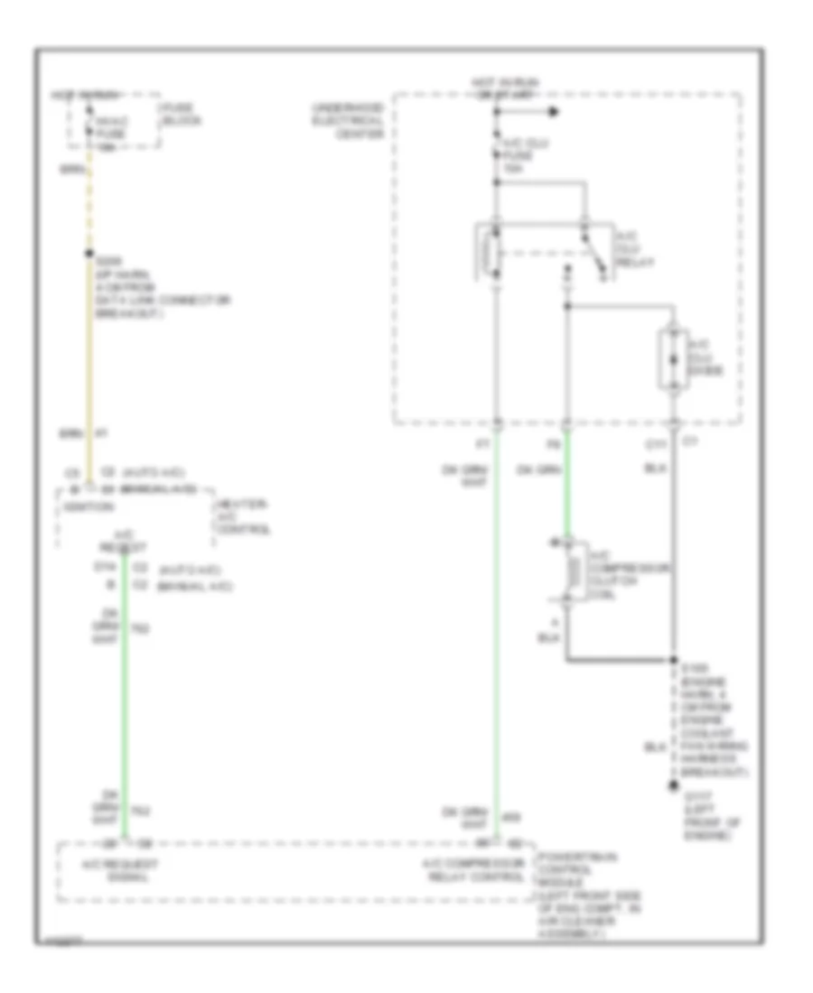
Compressor Wiring Diagram for Pontiac Grand Prix GTP 1999
List of elements for Compressor Wiring Diagram for Pontiac Grand Prix GTP 1999:
- (manual a/c) c1
- A/c clu diode
- A/c clu fuse 10a
- A/c clu relay
- A/c compressor clutch coil
- A/c compressor relay control
- A/c reqest
- A/c request
- C11
- C2 (auto a/c)
- C2 (manual a/c)
- D14
- Fuse block
- G117 (left front of engine)
- Harness breakout)
- Heater- a/c control
- Hot in run
- Hot in run or start
- Hvac fuse 10a
- Ignition
- Powertrain control module (left front side of eng compt, in air cleaner assembly)
- S206 (i/p harn, 4 cm from data link connector breakout)
- Signal
- Underhood electrical center
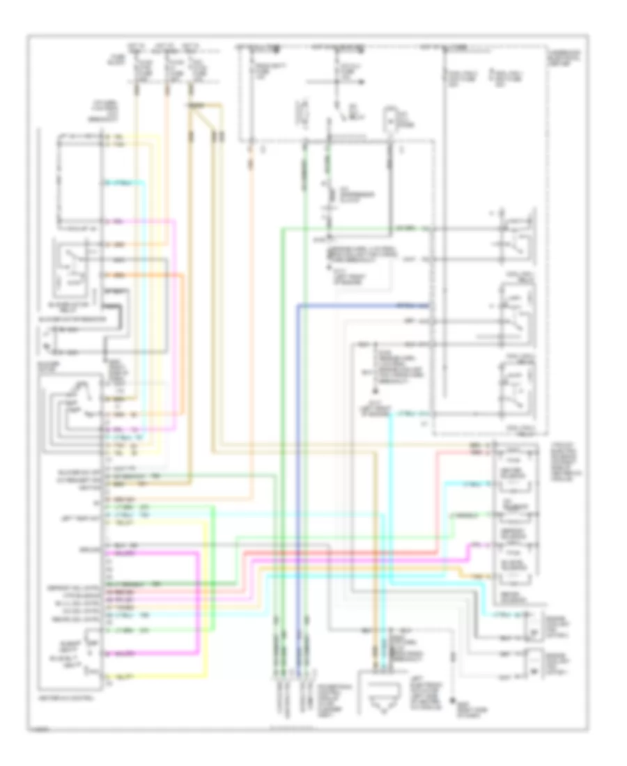
Manual A/C Wiring Diagram for Pontiac Grand Prix GTP 1999
List of elements for Manual A/C Wiring Diagram for Pontiac Grand Prix GTP 1999:
- (i/p harn, 4 cm from dlc breakout)
- A/c compressor clutch
- A/c clu diode
- A/c clu fuse 10a
- A/c clu relay
- A/c request sig
- A/c sol cntrl
- A/c solenoid
- A10
- Bi-level
- Bi-level solenoid
- Bi-lvl sol cntrl
- Blend
- Blower motor
- Blower motor relay
- Blower motor resistor
- Blower sw off
- C10
- C11
- Clutch req
- Comp ctrl
- Cool fan 1 maxi fuse 40a
- Cool fan 1 relay
- Cool fan 2 maxi fuse 30a
- Cool fan 2 relay
- Cool fan 3 relay
- Def
- Defrost sol cntrl
- Defrost solenoid
- Dic/ hvac fuse 10a
- Engine coolant fan motor 1
- Engine coolant fan motor 2
- F11
- Fuse block
- G117 (left front of engine)
- G200 (right side of dash)
- G200 (right side of dash) a
- Ground
- Heat
- Heater solenoid
- Heater-a/c control
- Hi spd ctrl
- Hot at all times
- Hot in on or start
- Hot in run
- Htr solenoid
- Hvac ctrl fuse 20a
- Hvac hi fuse 30a
- Ignition
- Left electronic actuator (left side of heater- a/c module)
- Left temp act
- Low spd ctrl
- Max
- Nca
- Off
- Powertrain control module (in air cleaner assy)
- Radio batt fuse 10a
- Recirc sol cntrl
- Recirc solenoid
- Red
- S105
- S105 (engine harn, 4 cm from engine coolant fan wiring harn breakout)
- S206
- S230 (i/p harn, 4 cm from radio breakout)
- Tan
- Underhood electrical center
- Vacuum/ electric solenoid (on right side of heater-a/c module)
- Vent

 Čeština
 Dansk
Dansk Deutsch
 Ελληνικά
 English
 Español
 Suomi
Suomi Français
 Français
 עברית
עברית Hrvatski
 Magyar
 Italiano
 日本語
日本語 한국어
한국어 Nederlands
 Polski
 Português
 Português
 Română
 Русский
 Slovenčina
 Slovenščina
 Svenska
 Türkçe
 中文 (中国)