AIR CONDITIONING
A/C Wiring Diagram for Suzuki Swift GA 1991
 https://portal-diagnostov.com/license.html
Automotive Electricians Portal FZCO
Automotive Electricians Portal FZCO
https://portal-diagnostov.com/license.html
https://portal-diagnostov.com/license.html
Automotive Electricians Portal FZCO
Automotive Electricians Portal FZCO
List of elements for A/C Wiring Diagram for Suzuki Swift GA 1991:
- 15a
- 20a
- 30a
- A/c
- A/c amplifier
- A/c switch
- A/t
- A/t control
- A10
- Acceleration switch
- Block
- Blower motor (right side of i/p)
- Blower switch
- Box
- C 1995 vftc
- Clutch
- Compressor
- Condenser fan motor (front of radiator)
- Condenser fan motor relay (on fuse/ relay block)
- Coolant temperature switch (on rear of cylinder head)
- Dual pressure switch (in high pressure line)
- Engine control module (left side of i/p)
- Engine controls system (diode module)
- Fuse
- Fuse block
- Fuse block (left side of i/p)
- Heater
- Hot at all times
- Hot in on or start
- Hot in run
- Ig fuse 20a
- Illumination
- In-line fuse
- Interior lights system
- M/t
- Magnet clutch relay (on fuse/ relay block)
- Main
- Main fuse
- Module
- Off
- Pin #24
- Pnk
- Radiator fan fuse (left side of safety wall)
- Radiator fan motor
- Radiator fan relay (left front fender)
- Radiator fan thermo switch (rear of engine)
- Red
- Resistors (right side of i/p)
- Starting/ charging system
- Thermistor
- Vacuum switching valve (rear center of engine compt)
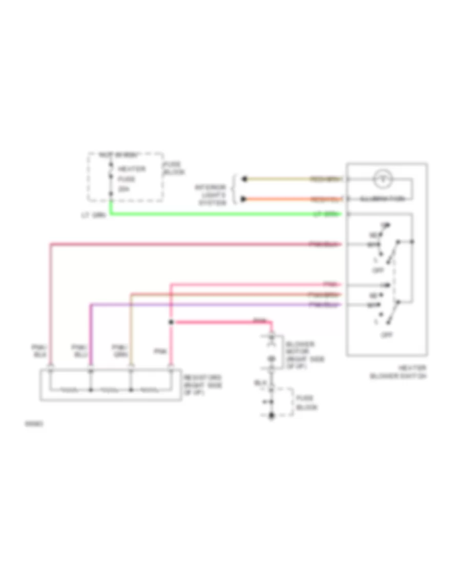
Heater Wiring Diagram for Suzuki Swift GA 1991
List of elements for Heater Wiring Diagram for Suzuki Swift GA 1991:
- 20a
- Block
- Blower motor (right side of i/p)
- Blower switch
- Fuse
- Fuse block
- Heater
- Hot in run
- Illumination
- Interior lights system
- Off
- Pnk
- Resistors (right side of i/p)
 Čeština
 Dansk
Dansk Deutsch
 Ελληνικά
 English
 English
 Español
 Suomi
Suomi Français
 Français
 עברית
עברית Magyar
 Italiano
 日本語
日本語 한국어
한국어 Nederlands
 Polski
 Português
 Português
 Română
 Русский
 Slovenčina
 Slovenščina
 Svenska
 Türkçe
 中文 (中国)
 Hrvatski