AIR CONDITIONING
A/C Wiring Diagram for Toyota Celica GT 1997
 https://portal-diagnostov.com/license.html
Automotive Electricians Portal FZCO
Automotive Electricians Portal FZCO
https://portal-diagnostov.com/license.html
https://portal-diagnostov.com/license.html
Automotive Electricians Portal FZCO
Automotive Electricians Portal FZCO
List of elements for A/C Wiring Diagram for Toyota Celica GT 1997:
- (a/c harness, at right kick panel)
- (engine rm harn, right side of engine compt)
- (engine room harn, front center of engine compt)
- (engine room harn, left rear corner of engine compt)
- (left front of engine compt)
- (right front of engine compt)
- (right kick panel)
- 1.8l
- 1994 vftc c
- 2.2l only
- A/c
- A/c amplifier (right side of i/p)
- A/c condenser fan motor
- A/c dual pressure switch (left front of engine compt)
- A/c fuse 10a
- A/c high pressure switch (left front of engine compt)
- A/c magnetic clutch & lock sensor (right front of engine)
- A/c magnetic clutch relay
- A/c thermistor (right side of i/p)
- A/c+
- Ac1
- Ac1 aca
- Acid
- Act
- Air inlet control servo motor (right side of i/p)
- Air vent mode control servo motor (center of i/p)
- B/l
- Blower motor (right side of i/p)
- Blower resistor (right side of i/p)
- Blower switch
- Case grounded for 1.8l
- Cds fan fusible link 30a
- Control circuit
- Control switch
- Def
- Ecu-ig fuse 15a
- Engine control module (right side of i/p)
- Face
- Fan relay no. 2
- Fan relay no. 3
- Fid
- Foot
- Frs
- G101 (right front fender)
- G203 (r/b 4 set bolt)
- G203 (r/b 4 set bolt) j/c 9 (right kick panel)
- Gnd
- Heater control switch
- Heater fuse 40a
- Heater relay
- Hot at all times
- Hot in run or start
- Htr fuse 10a
- I11 (cowl harn, center of i/p)
- I16
- Ig+
- Ign
- Igniter (left rear of engine compt)
- Ill+
- Ill-
- Interior lights system
- J/b 1 (left side of i/p)
- J/c 5 (right side of i/p)
- J/c 6 (behind right side of i/p)
- J/c 9
- Led
- Lock
- Mgc
- Prs
- R/b 2 (left side engine compt)
- R/b 2 (left side of engine compt)
- R/b 4
- R/b 4 (right kick panel)
- R/b 5 (right front of engine compt)
- Radiator fan motor
- Radiator fan relay no. 1
- Rdi fan fusible link 30a
- Rec
- Red
- Water temperature switch (right radiator support)
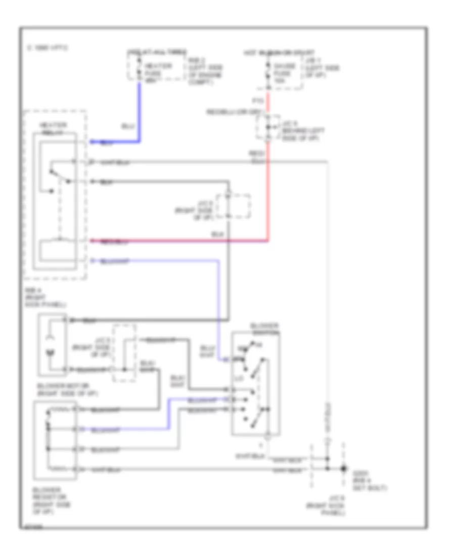
Heater Wiring Diagram for Toyota Celica GT 1997
List of elements for Heater Wiring Diagram for Toyota Celica GT 1997:
- Blower motor (right side of i/p)
- Blower resistor (right side of i/p)
- Blower switch
- C 1995 vftc
- F13
- G203 (r/b 4 set bolt)
- Gauge fuse 10a
- Heater fuse 40a
- Heater relay
- Hot at all times
- Hot in run or start
- J/b 1 (left side of i/p)
- J/c 5 (right side of i/p)
- J/c 6 (behind left side of i/p)
- J/c 9 (right kick panel)
- R/b 2 (left side of engine compt)
- R/b 4 (right kick panel)

 Čeština
 Dansk
Dansk Deutsch
 Ελληνικά
 English
 Español
 Suomi
Suomi Français
 Français
 עברית
עברית Hrvatski
 Magyar
 Italiano
 日本語
日本語 한국어
한국어 Nederlands
 Polski
 Português
 Português
 Română
 Русский
 Slovenčina
 Slovenščina
 Svenska
 Türkçe
 中文 (中国)