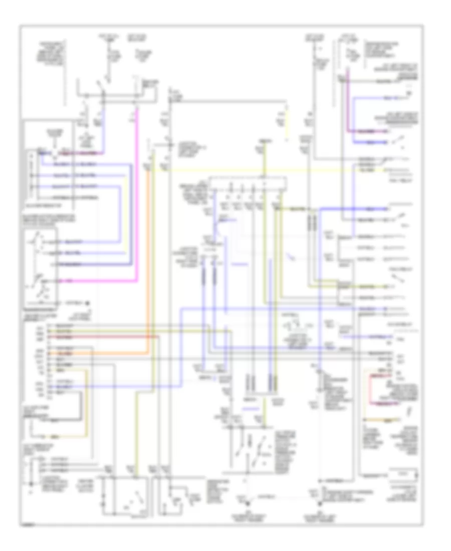
AIR CONDITIONING
Heater Wiring Diagram for Toyota ECHO 2005
 https://portal-diagnostov.com/license.html
Automotive Electricians Portal FZCO
Automotive Electricians Portal FZCO
https://portal-diagnostov.com/license.html
https://portal-diagnostov.com/license.html
Automotive Electricians Portal FZCO
Automotive Electricians Portal FZCO
List of elements for Heater Wiring Diagram for Toyota ECHO 2005:
- A/c fuse 7.5a
- Air inlet control servo motor (under upper right side of dash, on hvac housing)
- Alt
- Blower motor
- Blower motor & resistor (behind right side of dash, in hvac housing)
- Blower resistor
- Blower switch
- Control circuit
- Ecu-ig fuse 7.5a
- Engine control module (ecm) (behind lower right side of dash)
- Engine room r/b (on left side of engine compartment)
- F/d
- Foot
- Foot mode switch
- Frs
- G10
- Gauge fuse 10a
- Generator
- Gnd
- H11
- Hatch back
- Heater relay
- Heater sub 1 relay
- Hot at all times
- Hot in on or start
- Htr fuse 40a
- Htr sub 1 fuse 50a
- Id (at left kick panel)
- If (at right kick panel)
- Inlet air position detection switch (inside switch)
- Instrument panel j/b (behind left side of dash, near base of ``a" pillar)
- Junction connector (left side of dash)
- Junction connector 7 (below instrument cluster)
- Junction connector 9 (behind right kick panel)
- Max hot
- Max hot & foot mode switch
- Max hot switch
- Mhsw
- Mode in
- Off
- Position switches
- Ptc amplifier (behind upper right side of dash, near instrument cluster)
- Ptc heater (behind left center of dash)
- Ptc1
- Ptu
- R/f1
- Rec
- Rec/frs
- Red
- Tach
- Tw1
- W/ tacho- meter
- W/o tacho- meter
- Water temperature sensor (behind upper right side of dash)
Manual A/C Wiring Diagram for Toyota ECHO 2005
List of elements for Manual A/C Wiring Diagram for Toyota ECHO 2005:
- (at left front of engine compartment)
- (on left side of engine compartment) engine room r/b
- A/c
- A/c amplifier (right side of dash)
- A/c condenser fan resistor (left front of engine compartment, behind headlight)
- A/c fuse 7.5a
- A/c magnetic valve (lower left side of engine)
- A/c mg relay
- A/c thermistor (right side of dash)
- A/c triple pressure switch (a/c dual & single pressure dual switch) (on right side of engine compt)
- A10
- Ac1
- Act
- Blower motor
- Blower motor & resistor (behind right side of dash, in hvac housing)
- Blower resistor
- Blower switch
- Center
- Center cluster switch
- Cfn+
- Cfn-
- Cluster
- Def
- Defroster mode detection switch (inside switch)
- E4 (in engine compt harness, at left side of engine compartment)
- Ea (on rear of right front fender)
- Ec (on rear of left front fender)
- Ecu-ig fuse 7.5a
- Engine control module (ecm) (behind lower right side of dash)
- Engine coolant temperature sensor (on rear of cylinder head)
- Engine room r/b (on left side of engine compartment)
- Fan
- Fan 1 relay
- Fan 2 relay
- Foot & def
- Gauge fuse 10a
- Gnd
- H18
- Hatch back
- Heater relay
- Hot at all times
- Hot in on or start
- Htr fuse 40a
- I10
- I2 (in dash harness, behind right side of dash)
- Id (at left kick panel)
- If (at right kick panel)
- Instrument panel j/b (behind left side of dash, near base of ``a" pillar)
- J/c 1 (behind upper left side of dash, above instrument panel j/b)
- J13
- J14
- Junction connector 12 (left side of dash)
- Junction connector 9 (behind right kick panel)
- Junction connectors 13 & 14 (right side e of dash)
- Mgc
- Off
- Prs
- Radiator fan motor
- Rdi fuse 30a
- Sedan
- Single
- Switch
- Thw
 Čeština
 Dansk
Dansk Deutsch
 Ελληνικά
 English
 Español
 Suomi
Suomi Français
 Français
 עברית
עברית Hrvatski
 Magyar
 Italiano
 日本語
日本語 한국어
한국어 Nederlands
 Polski
 Português
 Português
 Română
 Русский
 Slovenčina
 Slovenščina
 Svenska
 Türkçe
 中文 (中国)
 English