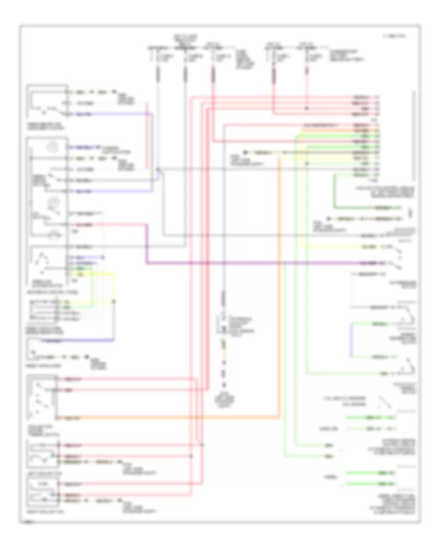
AIR CONDITIONING
Heater Wiring Diagram for Volkswagen Golf GL 1999
 https://portal-diagnostov.com/license.html
Automotive Electricians Portal FZCO
Automotive Electricians Portal FZCO
https://portal-diagnostov.com/license.html
https://portal-diagnostov.com/license.html
Automotive Electricians Portal FZCO
Automotive Electricians Portal FZCO
List of elements for Heater Wiring Diagram for Volkswagen Golf GL 1999:
- Fresh air blower (behind right side of dash, on hvac housing)
- Fresh air blower series resistance with fuse (behind right side of dash, on fresh air blower)
- Fresh air blower switch
- Fresh/ recirc switch
- Fresh/recirculating air door servo motor (on right corner of hvac housing)
- Fuse 25 25a
- Fuse 5 7.5
- Fuse panel (behind left side of dash)
- G206 (center of dash)
- Heater control panel
- Hot in run
- Hot w/ load reduction relay energized
- Interior lights system
- T6d
- T8b
Manual A/C Wiring Diagram for Volkswagen Golf GL 1999
List of elements for Manual A/C Wiring Diagram for Volkswagen Golf GL 1999:
- (1.9l and 2.0l engines)
- (2.8l engine only)
- (2.8l engine)
- 1995 vftc c
- A/c clutch
- A/c cut-out thermal switch
- A/c pressure switch
- A/c switch
- After-run coolant pump (2.8l engine only)
- Ambient temperature switch
- Coolant fan control module (at left front side of engine compartment)
- Coolant fan control thermal switch
- Diesel
- Diesel direct fuel injection engine control module (at base of windshield in center of plenum)
- Fresh air blower
- Fresh air blower series resistance
- Fresh air blower switch
- Fresh/ recirc switch
- Fresh/recirc air door servo motor
- Fuse 16 10a
- Fuse 25 25a
- Fuse 3 30a
- Fuse 5 7.5a
- Fuse 8 30a
- Fuse panel (behind left side of dash)
- Fuse/bracket battery (behind battery)
- G100 (left side of engine compt)
- G206 (center of dash)
- Gasoline
- Heater-a/c control panel
- Hot at all times
- Hot in run
- Hot w/ load reduction relay energized
- Interior lights system
- Left coolant fan
- Motronic engine control module (at base of windshield, in center of plenum)
- Red
- Right coolant fan
- T10b
- T4a
- T6d
- T8b

 Čeština
 Dansk
Dansk Deutsch
 Ελληνικά
 English
 Español
 Suomi
Suomi Français
 Français
 עברית
עברית Hrvatski
 Magyar
 Italiano
 日本語
日本語 한국어
한국어 Nederlands
 Polski
 Português
 Português
 Română
 Русский
 Slovenčina
 Slovenščina
 Svenska
 Türkçe
 中文 (中国)