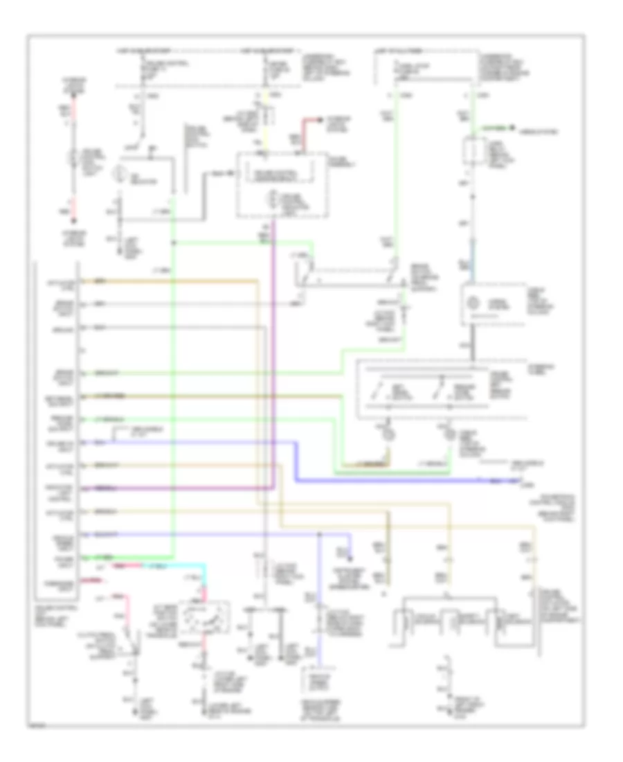
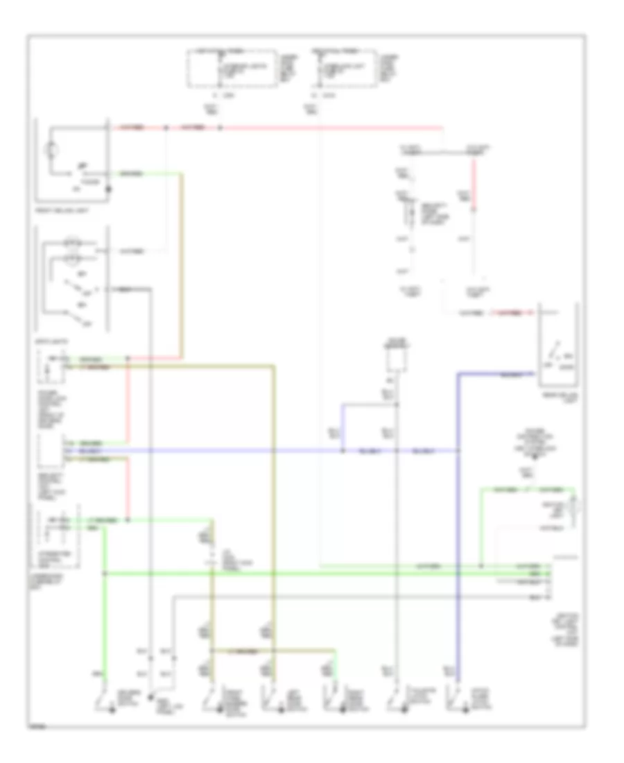
AIR CONDITIONING
Air Conditioning Wiring Diagrams for Honda CR-V LX 1997
 https://portal-diagnostov.com/license.html
Automotive Electricians Portal FZCO
Automotive Electricians Portal FZCO
https://portal-diagnostov.com/license.html
https://portal-diagnostov.com/license.html
Automotive Electricians Portal FZCO
Automotive Electricians Portal FZCO
List of elements for Air Conditioning Wiring Diagrams for Honda CR-V LX 1997:
- A/c pressure switch (left front of engine compt, on receiver/dryer)
- A17
- A27
- Acc
- Acs
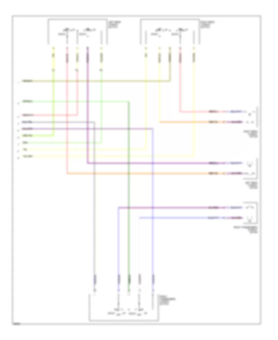
- Air mix control motor (below center of heater plenum)
- B/l
- Blower motor
- Blower motor high relay (on right side of plenum)
- Blower motor relay
- Compressor clutch
- Compressor clutch relay
- Condenser fan motor
- Condenser fan relay
- Def
- Defogger system
- Evaporator temperature sensor (center of heater plenum)
- Fanc
- Frs
- Fuse 20a
- Fuse 40a
- Fuse 7.5a
- G100 (left side of engine compt)
- G101 (right side of engine compt)
- G133 (center of engine)
- G200 (left kick panel)
- H/d
- Heater control panel
- Hot at all times
- Hot in on
- Ig2
- Interior lights system
- M-com
- Mode control motor (on left side of heater plenum)
- Power transistor (right side of heater plenum)
- Powertrain control module (at right kick panel)
- Radiator fan motor
- Radiator fan relay
- Radiator fan switch (middle of engine)
- Rec
- Recirculation control motor (right side of heater plenum)
- Red
- S-com
- S5v
- Under- dash fuse/ relay box
- Under- hood fuse/ relay box
- Vent
ANTI-LOCK BRAKES
Anti-lock Brake Wiring Diagrams for Honda CR-V LX 1997
List of elements for Anti-lock Brake Wiring Diagrams for Honda CR-V LX 1997:
- (1997)
- (1997-01)
- (1998-01)
- (1999)
- (behind right kick panel) g203
- (right front shock tower) g103
- (right kick panel) j/c c433
- +b1
- +b2
- A10
- A11
- A12
- A13
- A14
- A15
- A16
- A17
- A18
- A19
- A20
- A21
- A22
- Abs +b fuse 62 20a
- Abs control unit (behind right kick panel)
- Abs fuse 16 7.5a
- Abs indicator circuit
- Abs indicator light
- Abs modulator unit (on right rear of engine compartment)
- Abs pump motor (on right rear of engine compartment)
- Abs pump motor relay
- B10
- B11
- B12
- B13
- B14
- B15
- B16
- B17
- B18
- B19
- B20
- B21
- B22
- B23
- B24
- B25
- B26
- Brake switch (on brake pedal support)
- C352
- C359
- C360
- C417
- C502
- Conn a
- Conn b
- Data link connector (dlc) (partial) (behind right side of front console)
- Dlc
- Fl-in
- Fl-out
- Fl0
- Fl1
- Fr-in
- Fr-out
- Fr0
- Fr1
- Fuse 63 mtr check 7.5a
- G200 (left kick panel)
- Gauge assembly
- Gnd1
- Gnd2
- Gnd3
- Horn, stop fuse 52 15a
- Hot at all times
- Hot in on
- Hot in on or start
- Ig2
- J/c c433 (right kick panel)
- J/c c508 (behind left side of dash)
- Left front abs sol (in)
- Left front abs sol (out)
- Left front wheel sensor (inside wheel)
- Left rear abs sol (in)
- Left rear abs sol (out)
- Left rear wheel sensor (inside wheel)
- Mck
- Meter fuse 25 7.5a
- Pcom
- Pmr
- Pump motor fuse 61 40a
- Red
- Right front abs sol (in)
- Right front abs sol (out)
- Right front wheel sensor (inside wheel)
- Right rear abs sol (in)
- Right rear abs sol (out)
- Right rear wheel sensor (inside wheel)
- Rl-in
- Rl-out
- Rl0
- Rl1
- Rr-in
- Rr-out
- Rr0
- Rr1
- Scom
- Scs
- Service check connector (partial) (behind right side of front console)
- Stop
- Underdash fuse/relay box (behind dash, left of steering column)
- Underhood abs fuse/relay box (on right rear corner of engine compartment)
- Underhood fuse/relay box (on right rear corner of engine compt)
- Walp
ANTI-THEFT
Anti-theft Wiring Diagram for Honda CR-V LX 1997
List of elements for Anti-theft Wiring Diagram for Honda CR-V LX 1997:
- (left kick panel) g200
- (left side of engine compartment) g100
- 1997 model
- 1998-01
- B13
- B14
- Battery
- C352
- C419
- C552
- Ceiling light
- Disarm/valet sw input
- Disarm/valet switch (behind left side of dash)
- Door locks system
- Door sw input
- Door switch input
- Driver's door switch
- Front passenger's door switch
- Fuse 2 security 3a
- Fuse 25 meter 7.5a
- Fuse 48 headlight 30a
- Gauge assembly
- Glass breakage microphone
- Ground
- Hatch glass latch switch
- Hatch glass open ctrl
- Hood sw input
- Hood switch (optional) (right front corner of engine compartment)
- Horn ctrl
- Horns system
- Hot at all times
- Hot in on or start
- Ign key sw input
- Ignition
- Ignition key light control unit (behind left side of dash)
- Ignition key switch (closed with key in ignition)
- Integrated control unit
- Interior & exterior lights systems
- Interior lights system (rear ceiling light)
- J/c c433 (behind right kick panel)
- Key in
- Left rear door switch
- Light flasher relay (behind right side of dash)
- Light flasher rly ctrl
- Lock input
- Lock output
- Model
- Nca
- Pnk
- Power door lock control unit (in driver's door)
- Red
- Right rear door switch
- Security control unit (behind left kick panel)
- Security ind ctrl
- Security indicator
- Security siren (optional) (left rear of engine compartment)
- Select unlock rly ctrl
- Siren ctrl
- Starter cut rly ctrl
- Starting/ charging system
- Steering lock
- Tailgate latch switch
- Tailgate open ind
- Tailgate/hatch sw in
- Trunk, tailgate, fuel doors system
- Underdash fuse/relay box (behind dash, left of steering column)
- Underhood fuse/relay box (on right rear corner of engine compartment)
- Unlock input
- Unlock output
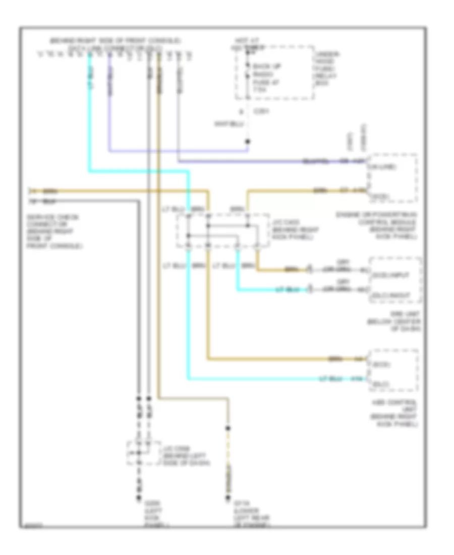
COMPUTER DATA LINES
Computer Data Lines for Honda CR-V LX 1997
List of elements for Computer Data Lines for Honda CR-V LX 1997:
- (1997) c8
- (1998-01) a21
- (behind right side of front console) data link connector (dlc)
- (dlc)
- (dlc) in/out
- (k-line)
- (scs)
- (scs) input
- A10
- A14
- Abs control unit (behind right kick panel)
- Back up
- C351
- Engine or powertrain control module (behind right kick panel)
- Fuse 47 7.5a
- G114 (lower left rear of engine)
- G200 (left kick panel)
- Hot at all times
- J/c c433 (behind right kick panel)
- J/c c508 (behind left side of dash)
- Radio
- Service check connector (behind right side of front console)
- Srs unit (below center of dash)
- Under- hood fuse/ relay box
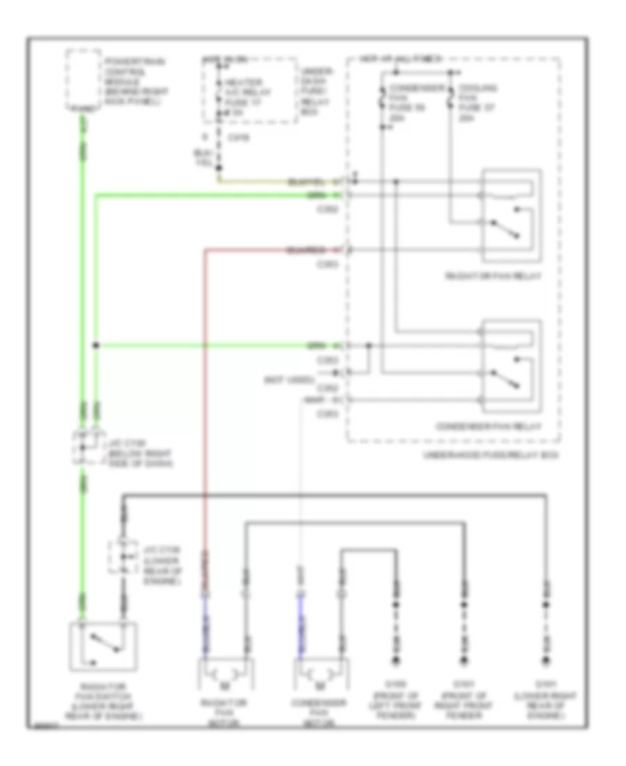
COOLING FAN
Cooling Fan Wiring Diagram for Honda CR-V LX 1997
List of elements for Cooling Fan Wiring Diagram for Honda CR-V LX 1997:
- (front of left front fender)
- (front of right front fender
- (lower rear of engine)
- (lower right rear of engine)
- (not used)
- A27
- C352
- C353
- C418
- Condenser fan fuse 56 20a
- Condenser fan motor
- Condenser fan relay
- Cooling fan fuse 57 20a
- Fanc
- G100
- G101
- Heater a/c relay fuse 17 7.5a
- Hot at all times
- Hot in on
- J/c c130 (below right side of dash)
- J/c c136
- Powertrain control module (behind right kick panel)
- Radiator fan motor
- Radiator fan relay
- Radiator fan switch (lower right rear of engine)
- Under- dash fuse/ relay box
- Under-hood fuse/relay box
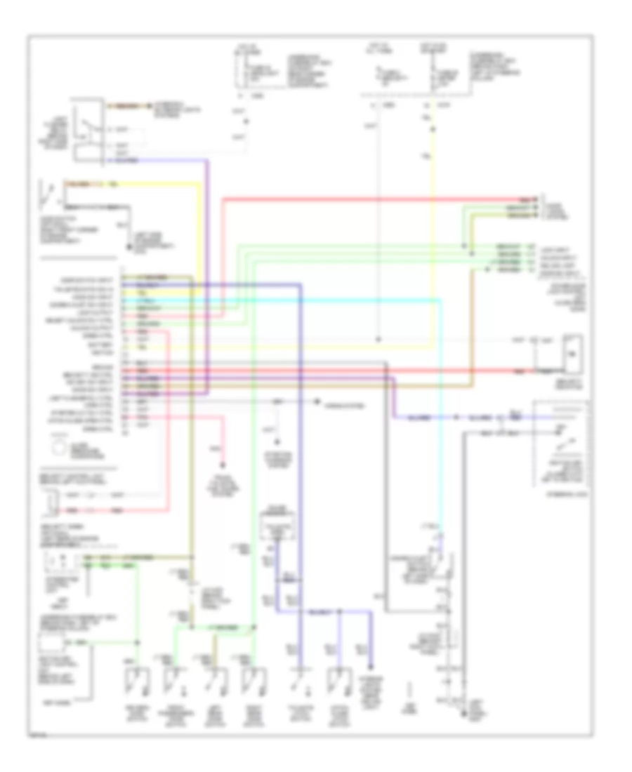
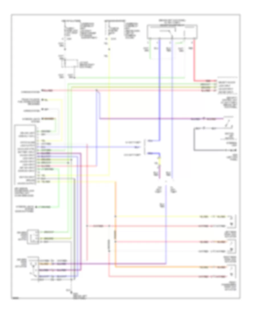
CRUISE CONTROL
Cruise Control Wiring Diagram for Honda CR-V LX 1997
List of elements for Cruise Control Wiring Diagram for Honda CR-V LX 1997:
- "on" indicator
- (front of left front fender) g100
- (left kick panel) g200
- (lower left rear of engine) g114
- 1998 models w/ a/t
- 1998 models w: a/t
- A/t
- A/t gear position switch (on lower rear of transaxle)
- Actuator ctrl
- Brake switch (on brake pedal support)
- Brake switch input
- C352
- C353
- C502
- Cable reel (top of steering column)
- Clutch pedal switch (on clutch pedal support)
- Crs
- Cruise control actuator (on left side of engine compartment)
- Cruise control dimming circuit
- Cruise control fuse 14 7.5a
- Cruise control indicator light
- Cruise control main switch
- Cruise control main switch light
- Cruise control set/ resume switch
- Cruise control unit (behind left kick panel)
- Cruise on input
- Disengage input
- Gauge assembly
- Ground
- Horn relay (behind left kick panel)
- Horn, stop fuse 52 15a
- Horns system
- Hot at all times
- Hot in on or start
- Indicator light control
- Instrument cluster system (speedometer)
- Interior lights system
- J/c c122 (below right side of dash, taped back to harness)
- J/c c136 (lower left front side of engine)
- J/c c433 (behind right kick panel)
- J/c c508 (behind left side of dash)
- M/t
- Meter fuse 25 7.5a
- Nca
- Off
- Pnk
- Power input
- Powertrain control module (pcm) (behind right kick panel)
- Red
- Resume/ accel sig input
- Resume/ accel switch
- Safety solenoid
- Set/ decel switch
- Set/decel sig input
- Steering wheel
- Underdash fuse/relay box (behind dash, left of steering column)
- Underhood fuse/relay box (on right rear corner of engine compartment)
- Vacuum solenoid
- Vehicle speed input
- Vehicle speed output
- Vehicle speed sensor (vss) (on top left of transaxle)
- Vent solenoid
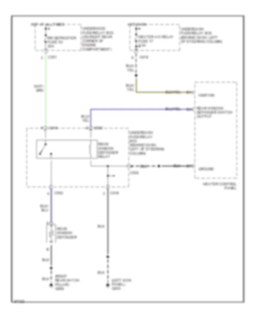
DEFOGGERS
Defogger Wiring Diagram for Honda CR-V LX 1997
List of elements for Defogger Wiring Diagram for Honda CR-V LX 1997:
- (left kick panel) g200
- (right rear hatch pillar) g998
- C351
- C418
- C502
- C552
- Ground
- Heater a/c relay fuse 17 7.5a
- Heater control panel
- Hot at all times
- Hot in on
- Ignition
- Rear window defogger
- Rear window defogger relay
- Rear window defogger switch output
- Rr defroster fuse 50 20a
- Underdash fuse/relay box (behind dash, left of steering column)
- Underdash fuse/relay box (behind dash, left of steering column)
- Underhood fuse/relay box (on right rear corner of engine compartment)
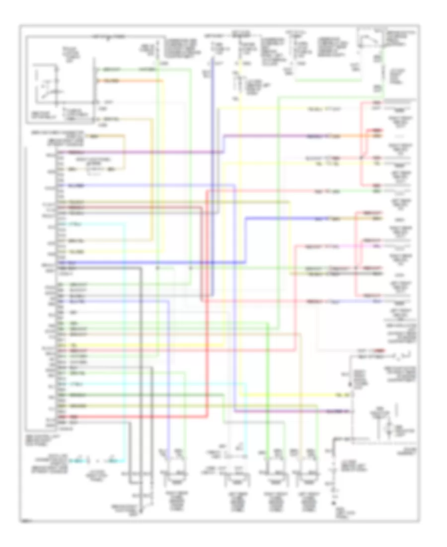
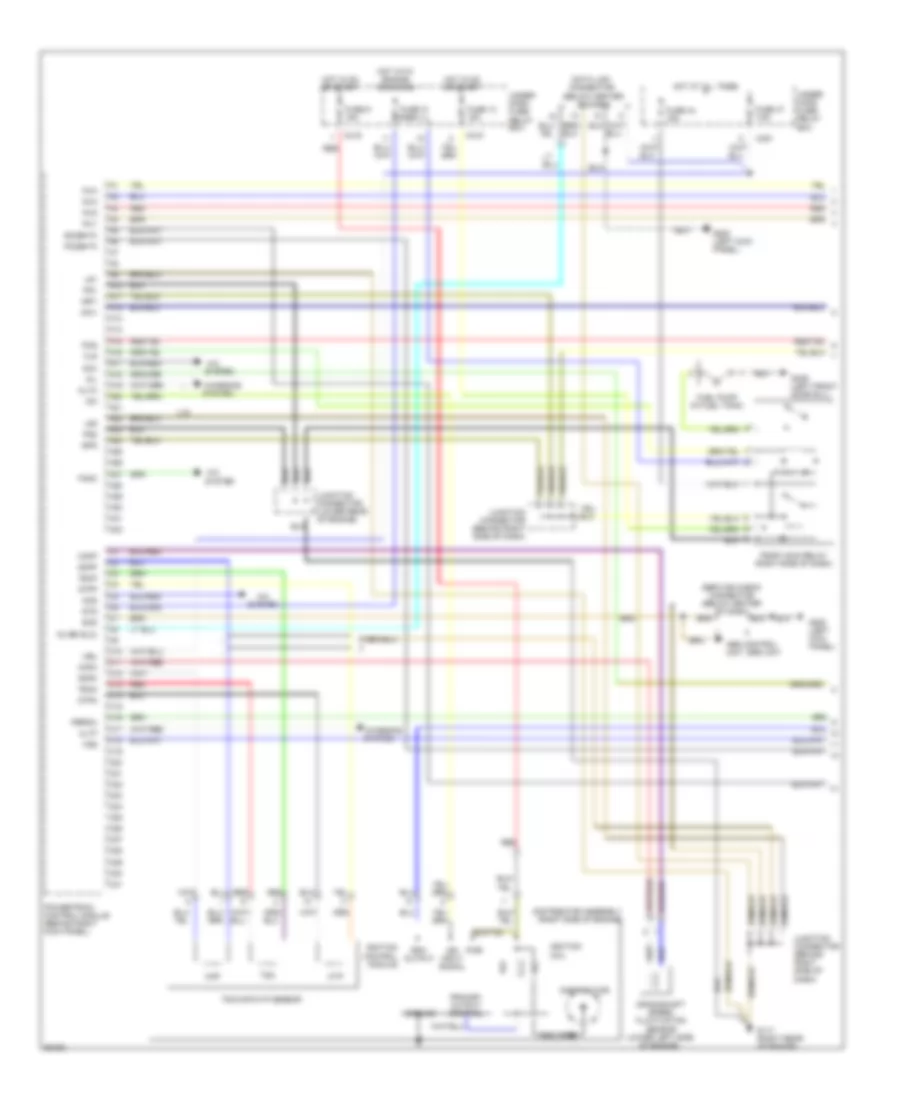
ENGINE PERFORMANCE
2.0L
2.0L, Engine Performance Wiring Diagrams (1 of 3) for Honda CR-V LX 1997
List of elements for 2.0L, Engine Performance Wiring Diagrams (1 of 3) for Honda CR-V LX 1997:
- (below center of dash)
- A/c
- A/c system
- A10
- A11
- A12
- A13
- A14
- A15
- A16
- A17
- A18
- A19
- A20
- A21
- A22
- A23
- A24
- A25
- A26
- A27
- A28
- A29
- A30
- A31
- A32
- Abs control unit, srs unit
- Acc
- Acs
- Altc
- Altf
- Box
- C10
- C11
- C12
- C13
- C14
- C15
- C16
- C17
- C18
- C19
- C20
- C21
- C22
- C23
- C24
- C25
- C26
- C27
- C28
- C29
- C30
- C31
- C351
- C418
- C419
- Charging
- Ckfm
- Ckfp
- Ckp
- Ckpm
- Ckpp
- Coil wire
- Crankshaft speed fluctuation sensor (lower left side of engine)
- Cyp
- Cypm
- Cypp
- Data link connector
- Distributor
- Distributor assembly (right side of engine)
- Fanc
- Flr
- Fuel pump (in fuel tank)
- Fuse 13 15a
- Fuse 31 7.5a
- Fuse 44 15a
- Fuse 47 7.5a
- Fuse 9 15a
- G117 (right rear of engine)
- G200 (left kick panel)
- G309 (left front door sill)
- Ground
- Hot at all times
- Hot in on or start
- Hot with engine cranking
- Iacv
- Icm
- Ign input signal
- Ignition coil
- Ignition control module
- Igp1
- Igp2
- Inj1
- Inj2
- Inj3
- Inj4
- Junction connector (behind right side of dash)
- Junction connector (lower rear of engine)
- Kline (dlc)
- Lg1
- Lg2
- Mil
- Pcs
- Pg1
- Pg2
- Pgm-fi main relay (right side of dash)
- Po2shtc
- Powertrain control module (behind right kick panel)
- Pri
- Primary output control
- Pspsw
- Pwr
- Red
- Rpm output
- Scs
- Sec
- Service check connector (below center of dash)
- So2shtc
- Sts
- System
- Tdc
- Tdc/ckp/cyp sensor
- Tdcm
- Tdcp
- U.s.
- Under- dash fuse/ relay box
- Under- hood fuse/ relay
- Vbu
- Vss
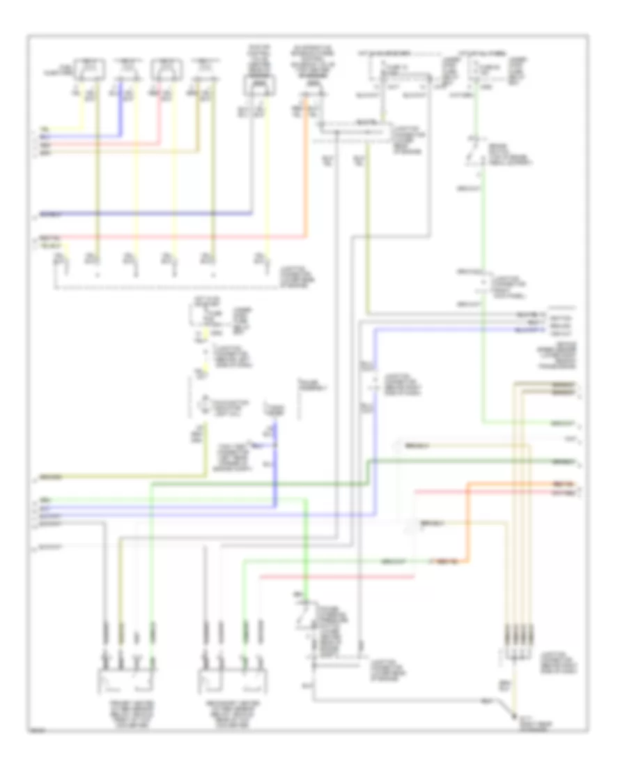
2.0L, Engine Performance Wiring Diagrams (2 of 3) for Honda CR-V LX 1997
List of elements for 2.0L, Engine Performance Wiring Diagrams (2 of 3) for Honda CR-V LX 1997:
- Brake switch (top of brake pedal support)
- C352
- C417
- C419
- C502
- Evaporative emission purge control solenoid valve (top center of engine)
- Fuel injectors
- Fuse 15 7.5a
- Fuse 52 15a
- Fuse 7.5a
- G117 (right rear of engine)
- Gauge assembly
- Ground
- Hot at all times
- Hot in on or start
- Idle air control valve (center rear of engine)
- Ignition
- Junction connector (behind left side of dash)
- Junction connector (behind right side of dash)
- Junction connector (lower rear of engine)
- Junction connector (right kick panel)
- Malfunction indicator light (mil)
- No. 1
- No. 2
- No. 3
- No. 4
- Power steering pressure switch (lower center rear of engine compt)
- Primary heated oxygen sensor (below vehicle, front of twc converter)
- Red
- Secondary heated oxygen sensor (below vehicle, rear of twc converter)
- Tach test connector (left rear corner of engine compt)
- Tacho- meter
- Under- dash fuse/ relay box
- Under- hood fuse/ relay box
- Vehicle speed sensor (lower right rear of transmission)
- Vss out
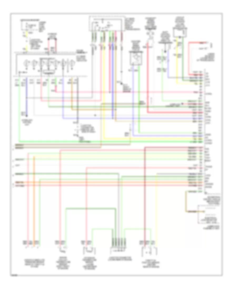
2.0L, Engine Performance Wiring Diagrams (3 of 3) for Honda CR-V LX 1997
List of elements for 2.0L, Engine Performance Wiring Diagrams (3 of 3) for Honda CR-V LX 1997:
- A/t gear position indicator
- A/t gear position switch (right side of transmission)
- A10
- A11
- A12
- A14
- Atp1
- Atp2
- Atpd3
- Atpd4
- Atpnp
- Atpr
- B10
- B19
- B20
- B21
- Bksw
- C502
- Control
- Control unit
- Counter- shaft speed sensor (top of transmission)
- D10
- D11
- D12
- D13
- D14
- D15
- D16
- D4 ind
- Dimming circuit
- Ect
- Electrical load detector (u.s.)
- Engine coolant temperature sensor (right front of engine)
- Fuse 25 7.5a
- G117 (right rear of engine)
- G200 (left kick panel)
- Gauge assembly
- Hot in on or start
- Iat
- Intake air temperature sensor (lower center rear of engine)
- Interior lights system
- Interlock
- Interlock control unit
- Junction connector (behind left side of dash)
- Junction connector (behind left side of dash)
- Junction connector (lower rear of engine)
- Lc a
- Lc b
- Linear solenoid (lower front of transmission)
- Lock-up control solenoid valves (front of transmission)
- Ls+
- Ls-
- Mainshaft speed sensor (lower right rear of engine)
- Manifold absolute pressure sensor (rear of throttle intake)
- Map
- Ncsg
- Nmsg
- Pho2s
- Pnk
- Pnk b8
- Powertrain control module (behind right kick panel)
- Red
- Red b15
- Red b2
- Sg1
- Sg2
- Sh02sg
- Sha
- Shb
- Shift control solenoid valves (front of transmission)
- Sho2s
- Slu
- Throttle position sensor (center rear of engine)
- Tps
- Under- dash fuse/ relay box
- Under-hood fuse/relay box
- Unit
- Vcc1
- Vcc2
EXTERIOR LIGHTS
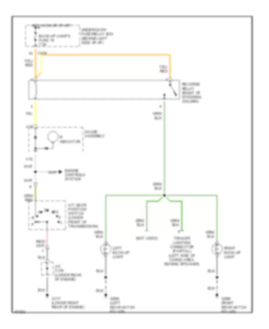
Back-up Lamps Wiring Diagram for Honda CR-V LX 1997
List of elements for Back-up Lamps Wiring Diagram for Honda CR-V LX 1997:
- (not used)
- A/t gear position switch (lower front of transmission)
- A12
- A13
- Back-up lights fuse 19 7.5a
- C419
- Engine controls system
- G117 (lower right rear of engine)
- G998 (right rear hatch pillar)
- G999 (left rear hatch pillar)
- Gauge assembly
- Hot in on or start
- J/c c136 (lower rear of engine)
- Left back-up light
- R indicator
- Reverse relay (right of steering column)
- Right back-up light
- Trailer lighting connector (partial) (left side of cargo area behind speaker)
- Under-dash fuse/relay box (behind left side of i/p)
Exterior Lamps Wiring Diagram (1 of 2) for Honda CR-V LX 1997
List of elements for Exterior Lamps Wiring Diagram (1 of 2) for Honda CR-V LX 1997:
- C352
- C418
- C502
- C751
- Combination light switch
- G200 (left kick panel)
- Gauge assembly
- Ground
- Hazard fuse 53 10a
- Hazard warning switch
- Hot at all times
- Hot in on or start
- Ign/pwr
- Illumination lamp
- Interior lights system
- J/c c508 (left side of dash)
- Left
- Left turn signal indicator light
- Off
- Red
- Relay out
- Right
- Right turn signal indicator light
- To under-dash fuse/relay box (turn signal lights) (diagram 2 of 2)
- Turn lights fuse 12 7.5a
- Turn signal switch
- Turn signal/ hazard relay
- Under-dash fuse/relay box (behind left side of dash)
- Under-dash fuse/relay box (behind left side of i/p)
- Under-hood fuse/relay box (right rear of engine compt)
Exterior Lamps Wiring Diagram (2 of 2) for Honda CR-V LX 1997
List of elements for Exterior Lamps Wiring Diagram (2 of 2) for Honda CR-V LX 1997:
- (left side of cargo area behind speaker)
- Anti-theft system
- Back-up lamps circuit
- Brake light switch (left side of i/p)
- C352
- C417
- C418
- C502
- C551
- C552
- C751
- C752
- Combination light switch
- From hazard warning switch (diagram 1 of 2)
- From turn signal switch (diagram 1 of 2)
- G100 (front of left front fender)
- G101 (front of right front fender)
- G412 (center of tailgate)
- G998 (right rear hatch pillar)
- G999 (left rear hatch pillar)
- Head
- Headlight fuse 48 30a
- Headlight switch
- High mount brake light
- Horn, stop lt fuse 52 15a
- Hot at all times
- Interior lights system
- J/c c442 (right kick panel)
- Left brake light/ taillight
- Left front marker light
- Left front parking/ turn signal light
- Left rear side marker light
- Left rear turn signal light
- License light
- License lights taillights fuse 32 7.5a
- Light flasher relay (w/ anti-theft) (center of dash)
- Off
- Park
- Right brake light/ taillight
- Right front marker light
- Right front parking/ turn signal light
- Right rear side marker light
- Right rear turn signal light
- Trailer lighting connector
- Under-dash fuse/relay box (behind left side of i/p)
- Under-hood fuse/relay box (right rear of engine compt)
- W/ optional spoiler
- W/o optional spoiler
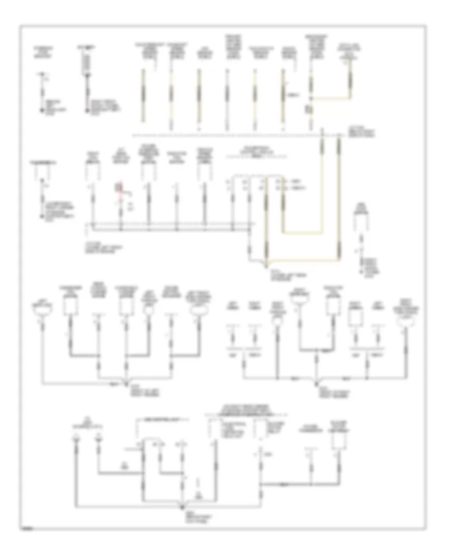
GROUND DISTRIBUTION
Ground Distribution Wiring Diagram (1 of 3) for Honda CR-V LX 1997
List of elements for Ground Distribution Wiring Diagram (1 of 3) for Honda CR-V LX 1997:
- (1998-01) b
- (behind left headlamp) g106
- (lower right front corner of engine compartment) g101
- (on right rear corner of engine compartment) underhood fuse/relay box
- (right front shock tower) g103
- (right front shock tower, near battery) g103
- 1998-01
- 1999-01
- A (1997)
- A/t
- A/t gear position switch
- Abs control unit
- Abs pump motor
- Battery
- Blower motor high relay
- Blower motor relay
- C351
- Ckf sensor shield
- Condenser fan motor
- Countershaft speed sensor shield
- Cruise control actuator
- Data link connector (dlc) (partial)
- Electrical load detector (eld) unit
- G100 (front of left front fender)
- G101 (front of right front fender)
- G114 (lower left rear of engine)
- G203 (behind right kick panel)
- J/c c122 (below right side of dash)
- J/c c136 (lower left front side of engine)
- Knock sensor shield
- Left front parking light
- Left front side marker/ turn signal light
- Left headlight
- Left horn
- Mainshaft speed sensor shield
- Pgm-fi main relay
- Power steering pressure (psp) switch
- Power transistor
- Powertrain control module (pcm)
- Primary heated oxygen sensor (ho2s) shield
- Radiator fan motor
- Radiator fan switch
- Rear window washer motor
- Right front parking light
- Right front side marker/ turn signal light
- Right headlight
- Right horn
- Secondary heated oxygen sensor (ho2s) shield
- Steering pump bracket
- Tdc/ckp/cyp sensor shield
- To g200 (diagram 2 of 3)
- Transmission
- Vehicle speed sensor (vss)
- W/ abs
- Windshield washer motor
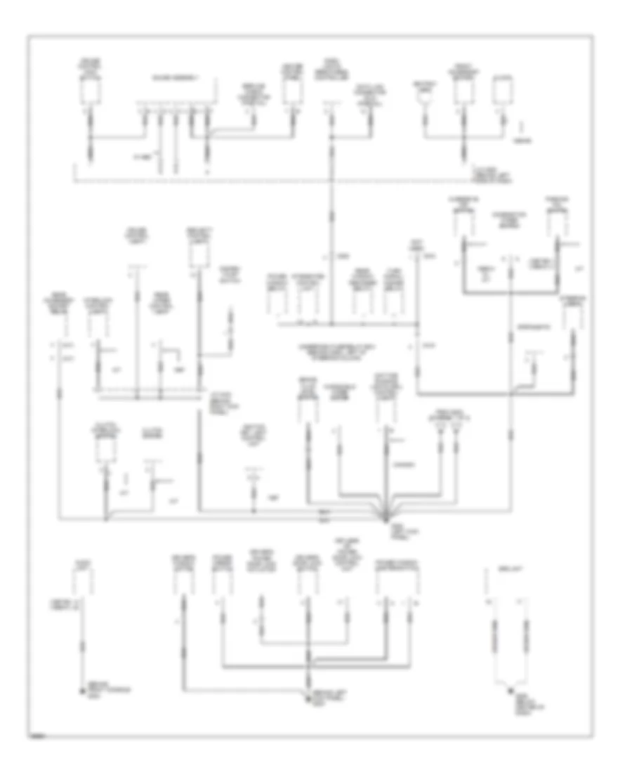
Ground Distribution Wiring Diagram (2 of 3) for Honda CR-V LX 1997
List of elements for Ground Distribution Wiring Diagram (2 of 3) for Honda CR-V LX 1997:
- (1997-98) (1999-01)
- (a/t)
- (behind front console) g302
- (behind left kick panel) g200
- (m/t)
- (not used)
- 1998-99
- 1999-01 w/ a/t
- A/t
- Ashtray light
- Audio unit
- Brake fluid level switch
- C418
- C502
- C910
- Canada
- Clock
- Clutch interlock switch
- Clutch switch
- Combination wiper switch
- Cruise control main switch
- Cruise control unit
- Dash lights brightness controller
- Data link connector (dlc) (partial)
- Daytime running lights (drl) control unit
- Disarm/ valet switch
- Driver's door lock switch
- Driver's power door lock actuator
- Driver's window motor
- From g203 (diagram 1 of 3)
- Front accessory socket
- G200 (left kick panel)
- G206 (below center of dash)
- Gauge assembly
- Heater control panel
- Ignition key light control unit
- Integrated control unit
- Interlock control unit
- J/c c433 (behind right kick panel)
- J/c c508 (behind left side of dash)
- Keyless or power door lock control unit
- M/t
- Overdrive off switch
- Parking pin switch
- Power mirror switch
- Power window master switch
- Power window relay
- Rear accessory socket relay
- Rear window defogger relay
- Rear wiper control unit
- Security control unit
- Service check connector (partial)
- Spotlights
- Srs unit
- Steering lock
- Turn signal/ hazard relay
- Underdash fuse/relay box (behind dash, left of steering column)
- W/ abs
- Windshield wiper motor
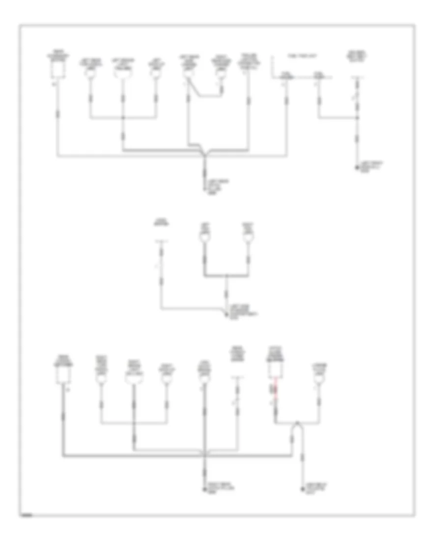
Ground Distribution Wiring Diagram (3 of 3) for Honda CR-V LX 1997
List of elements for Ground Distribution Wiring Diagram (3 of 3) for Honda CR-V LX 1997:
- (center of tailgate) g412
- (left front door sill) g309
- (left rear hatch pillar) g999
- (left side of engine compartment) g100
- (right rear hatch pillar) g998
- Driver's seat belt switch
- Fuel gauge
- Fuel pump
- Fuel tank unit
- Hatch glass opener solenoid
- High mount brake- light
- Hood switch
- Left back-up light
- Left brake- light/ taillight
- Left fog- light
- Left rear side marker light
- Left rear turn signal light
- License plate light
- Rear accessory socket
- Rear window defogger
- Rear window wiper motor
- Right back-up light
- Right brake light/ taillight
- Right fog- light
- Right rear side marker light
- Right rear turn signal light
- Trailer lighting connector (partial)
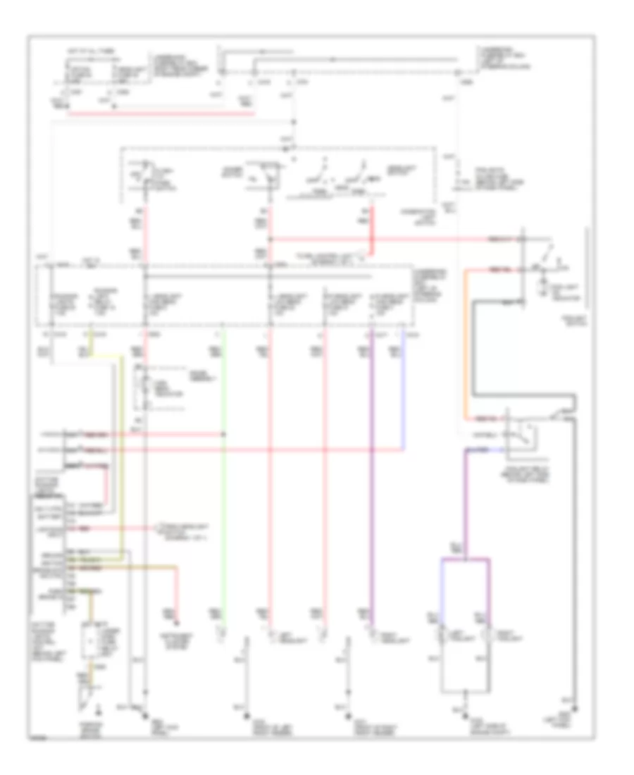
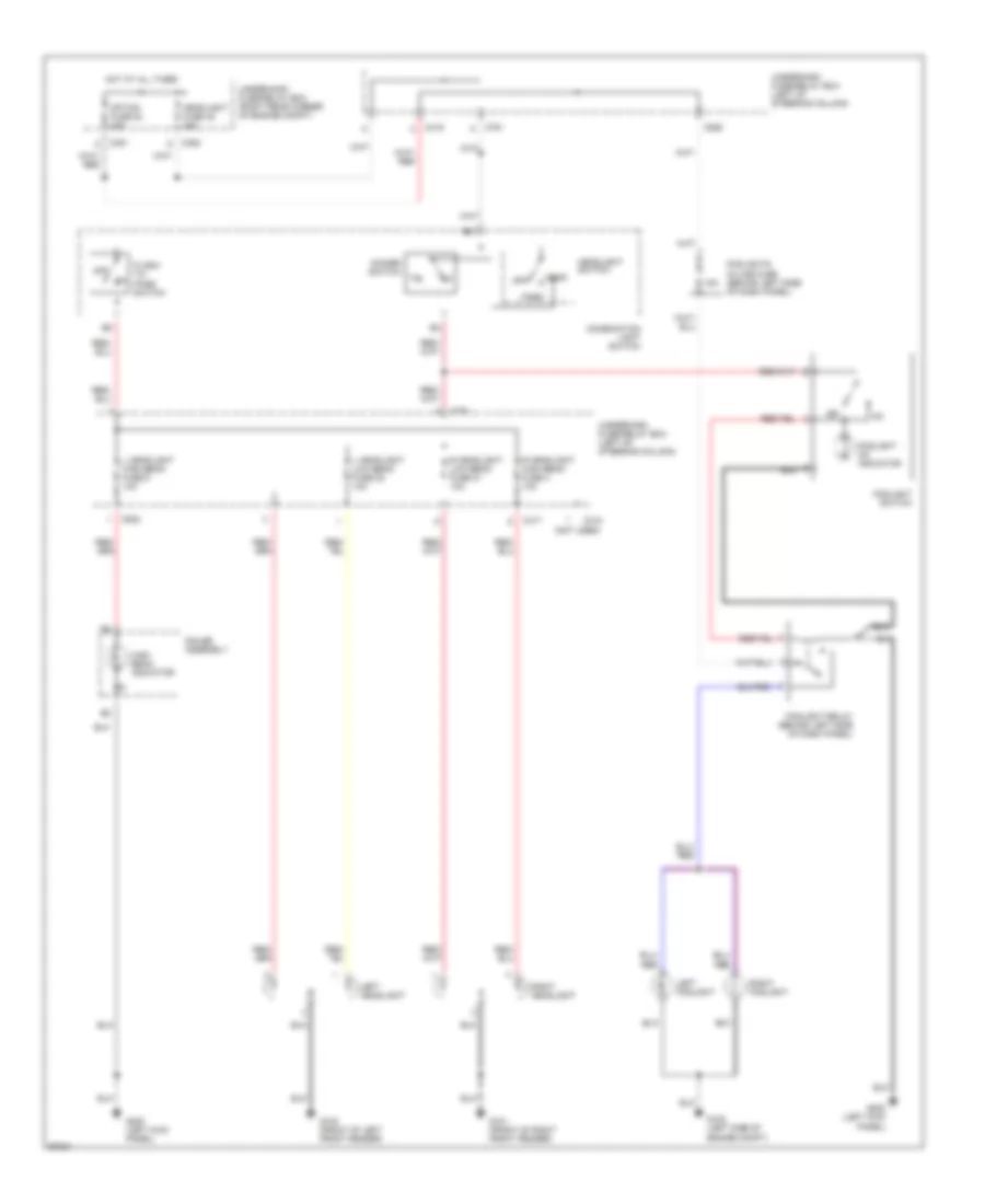
HEADLIGHTS
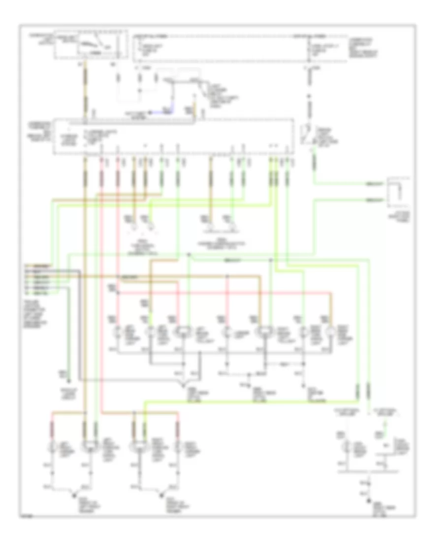
Headlight Wiring Diagram, with DRL for Honda CR-V LX 1997
List of elements for Headlight Wiring Diagram, with DRL for Honda CR-V LX 1997:
- 15a
- Battery
- Brake sys ind ctrl
- C351
- C352
- C417
- C418
- C419
- C502
- C552
- C751
- C925
- Combination light switch
- Daytime running lights control unit (behind left kick panel)
- Daytime running lights resistor
- Dimmer switch
- Flash- to- pass switch
- Fog light on indicator
- Foglight relay (behind left side of dash panel)
- Foglight switch
- Foglights in-line fuse (behind left side of dash panel)
- From headlight switch (diagram 1 of 1)
- G100 (front of left front fender)
- G100 (left side of engine compt)
- G101 (front of right front fender)
- G200 (left kick panel)
- Gauge assembly
- Ground
- Hdlt ctrl
- Head
- Headlight fuse 48 30a
- Headlight switch
- High beam indicator
- Hot at all times
- Hot in on
- Ignition
- Instrument cluster system
- L headlight high beam fuse 5 10a
- L headlight low beam fuse 22 10a
- Left foglight
- Left headlight
- Lights-on input
- Nca
- Off
- Option fuse 54 40a
- Park
- Park brake in
- Parking brake switch
- R headlight high beam fuse 4 10a
- R headlight low beam fuse 21 10a
- Red
- Right foglight
- Right headlight
- Running light relay fuse 18 7.5a
- Running lights fuse 20 7.5a
- To drl control unit (diagram 1 of 1)
- Under- dash fuse/ relay box
- Underdash fuse/relay box (left of steering column)
- Underhood fuse/relay box (right rear corner of engine compt)
Headlight Wiring Diagram, without DRL for Honda CR-V LX 1997
List of elements for Headlight Wiring Diagram, without DRL for Honda CR-V LX 1997:
- (not used)
- 15a
- C351
- C352
- C417
- C418
- C419
- C502
- C751
- C925
- Combination light switch
- Dimmer switch
- Flash- to- pass switch
- Foglight on indicator
- Foglight relay (behind left side of dash panel)
- Foglight switch
- Foglights in-line fuse (behind left side of dash panel)
- G100 (front of left front fender)
- G100 (left side of engine compt)
- G101 (front of right front fender)
- G200 (left kick panel)
- Gauge assembly
- Head
- Headlight fuse 48 30a
- Headlight switch
- High beam indicator
- Hot at all times
- L headlight high beam fuse 5 10a
- L headlight low beam fuse 22 10a
- Left foglight
- Left headlight
- Off
- Option fuse 54 40a
- Park
- R headlight high beam fuse 4 10a
- R headlight low beam fuse 21 10a
- Right foglight
- Right headlight
- Underdash fuse/relay box (left of steering column)
- Underhood fuse/relay box (right rear corner of engine compt)
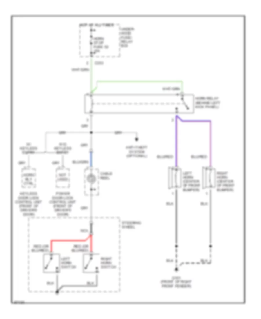
HORN
Horn Wiring Diagram for Honda CR-V LX 1997
List of elements for Horn Wiring Diagram for Honda CR-V LX 1997:
- Anti-theft system (optional)
- C353
- Cable reel
- G101 (front of right front fender)
- Horn relay (behind left kick panel)
- Horn rly ctrl
- Horn stop fuse 52 15a
- Hot at all times
- Keyless door lock control unit (front of driver's door)
- Left horn (center of front bumper)
- Left horn switch
- Nca
- Not used
- Power door lock control unit (front of driver's door)
- Right horn (center of front bumper)
- Right horn switch
- Steering wheel
- Under- hood fuse/ relay box
- W/ keyless entry
- W/o keyless entry
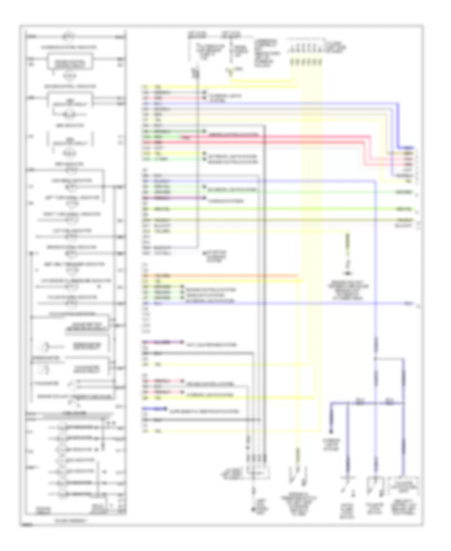
INSTRUMENT CLUSTER
Instrument Cluster Wiring Diagram (1 of 2) for Honda CR-V LX 1997
List of elements for Instrument Cluster Wiring Diagram (1 of 2) for Honda CR-V LX 1997:
- (left kick panel) g200
- 1 indicator
- 2 indicator
- A10
- A11
- A12
- A13
- A14
- Abs indicator
- Abs indicator circuit
- Alternator sp sensor fuse 15 7.5a
- Anti-lock brakes system
- B10
- B11
- B12
- B13
- B14
- B15
- B16
- Brake system indicator
- C10
- C11
- C12
- C13
- C502
- Charging system indicator
- Cruise control dimming circuit
- Cruise control indicator
- Cruise control system
- D3 indicator
- D4 indicator
- Dimming circuit
- Engine controls system
- Engine coolant temperature gauge
- Engine coolant temperature gauge sending unit (on rear of cylinder head)
- Engine oil pressure switch (on left side of engine, above oil filter)
- Exterior lights system
- Fuel gauge
- Gauge assembly
- Hatch glass latch switch
- Headlights system
- High beam indicator
- Hot in on or start
- Interior lights system
- J/c c508 (left side of dash)
- Left turn signal indicator
- Low engine oil pressure indicator
- Low fuel indicator
- Malfunction indicator
- Meter fuse 25 15a
- N indicator
- Odometer/trip meter drive circuit
- P indicator
- Pnk
- R indicator
- Red
- Right turn signal indicator
- Seat belt reminder indicator
- Security control unit (behind left kick panel)
- Solid state
- Speedometer
- Speedometer drive circuit
- Srs indicator
- Srs indicator circuit
- Starting/ charging system
- Tachometer
- Tachometer drive circuit
- Tailgate latch switch
- Tailgate open indicator
- Tailgate/ hatch glass input
- Underdash fuse/relay box (behind dash, left of steering column)
- Warning systems
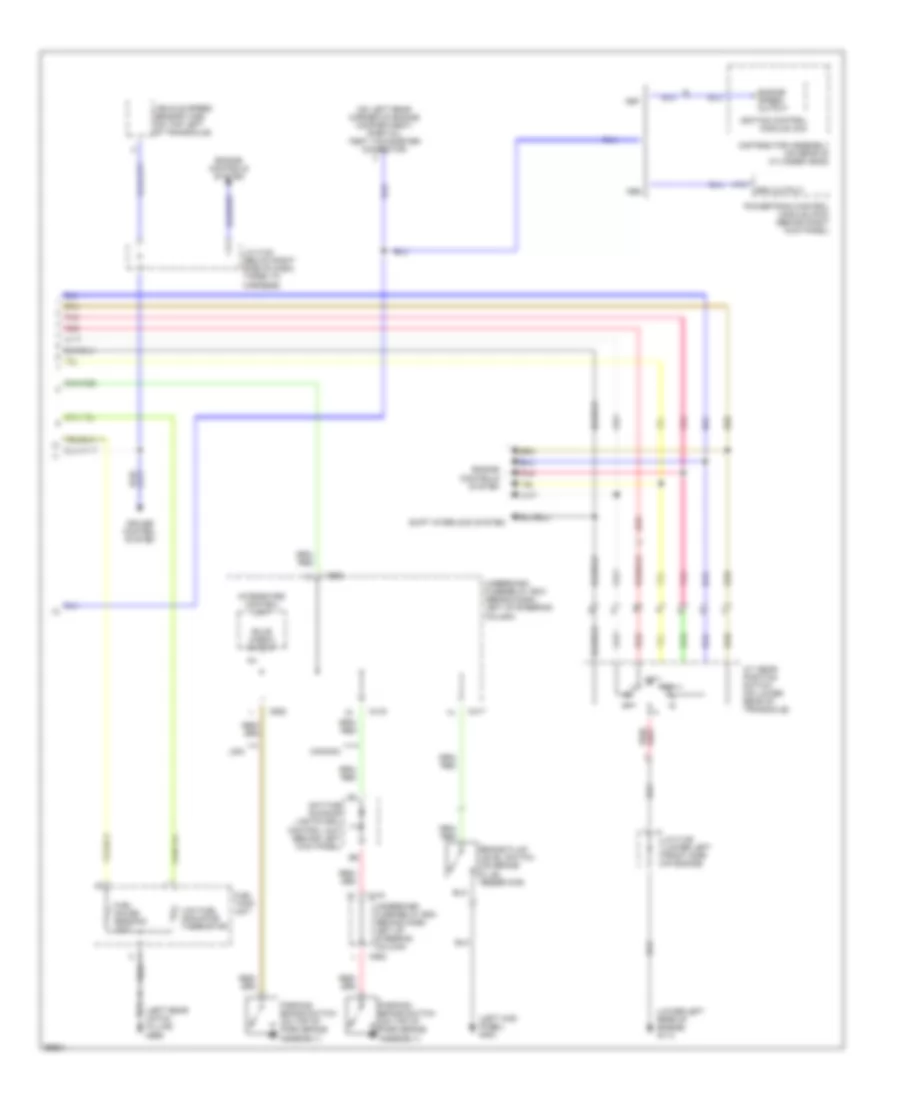
Instrument Cluster Wiring Diagram (2 of 2) for Honda CR-V LX 1997
List of elements for Instrument Cluster Wiring Diagram (2 of 2) for Honda CR-V LX 1997:
- (left kick panel) g200
- (left rear hatch pillar) g999
- (lower left rear of engine) g114
- (on left rear corner of engine compartment) (partial) test tachometer connector
- A/t gear position switch (on lower rear of transaxle)
- A19
- Brake fluid level switch (on brake fluid reservoir)
- Bulb check output
- C417
- C419
- C552
- Canada
- Cruise control system
- Daytime running lights (drl) control unit (behind left kick panel)
- Distributor assembly (on rear of cylinder head)
- Engine controls system
- Engine speed output
- Fuel gauge sending unit
- Fuel tank unit
- Ignition control module (icm)
- Integrated control unit
- J/c c122 (below right side of dash, taped to harness)
- J/c c136 (lower left front side of engine)
- Low fuel indicator thermistor
- Parking brake switch (on top of park brake assembly)
- Pnk
- Powertrain control module (pcm) (behind right kick panel)
- Red
- Rpm output
- Shift interlock system
- Underdash fuse/relay box (behind dash, left of steering column)
- Usa
- Vehicle speed sensor (vss) (on top left of transaxle)
INTERIOR LIGHTS
Courtesy Lamp Wiring Diagram for Honda CR-V LX 1997
List of elements for Courtesy Lamp Wiring Diagram for Honda CR-V LX 1997:
- C351
- C418
- Door
- Driver's door switch
- Front ceiling light
- Front pass- enger's door switch
- G200 (left lick panel)
- Gauge assembly
- Hatch glass latch switch
- Hot at all times
- Ignition key light
- Ignition key light control unit (left side of dash)
- Integrated control unit
- Interior lights fuse 43 7.5a
- Interlock unit fuse 33 7.5a
- J/c c433 (right kick panel)
- Left rear door switch
- Off
- Power distribution system (key interlock switch)
- Power door lock control unit (front of driver's door)
- Rear ceiling light
- Right rear door switch
- Security control unit (left kick panel)
- Security diode (left side of dash)
- Spotlights
- Tailgate latch switch
- Under- dash fuse/ relay box
- Under- hood fuse/ relay box
- Under-dash fuse/relay box
- W/ anti- theft
- W/o anti- theft
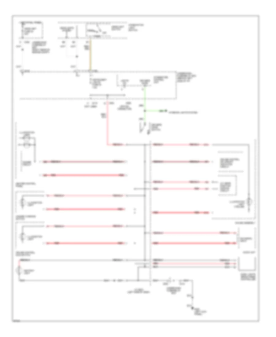
Instrument Illumination Wiring Diagram for Honda CR-V LX 1997
List of elements for Instrument Illumination Wiring Diagram for Honda CR-V LX 1997:
- (not used)
- (option connector)
- A/t gear position dimming circuit
- Ashtray light
- Audio unit
- C12
- C13
- C352
- C418
- C419
- C502
- C752
- C926
- Combination light switch
- Cruise control main switch
- Cruise control or upshift indicator circuit
- Dash lights brightness controller
- Dim signal input
- Dimmer circuit
- Driver's door in
- Driver's door switch
- G200 (left kick panel)
- Gauge assembly
- Hazard warning switch
- Head
- Headlight fuse 48 40a
- Headlight switch
- Headlights system
- Heater control panel
- Hot at all times
- Illumination light
- Illumination light (7-bulbs)
- Instrument lights fuse 30 7.5a
- Integrated control unit
- Interior lights system
- J/c c508 (left side of dash)
- Lights on in
- Off
- Park
- Red
- Under-dash fuse/relay box
- Under-dash fuse/relay box (behind left side of i/p)
- Under-hood fuse/relay box (right rear of engine compt)
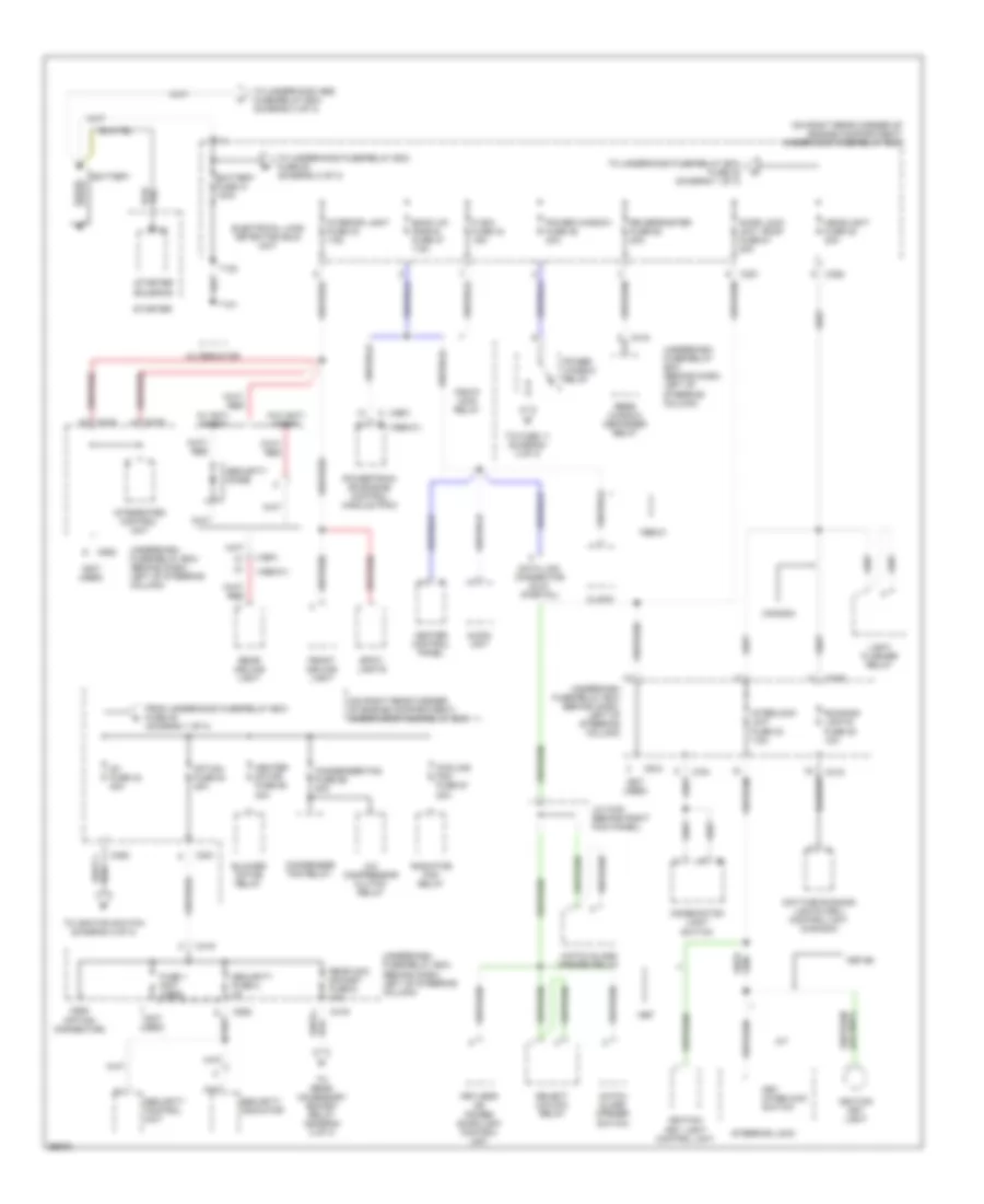
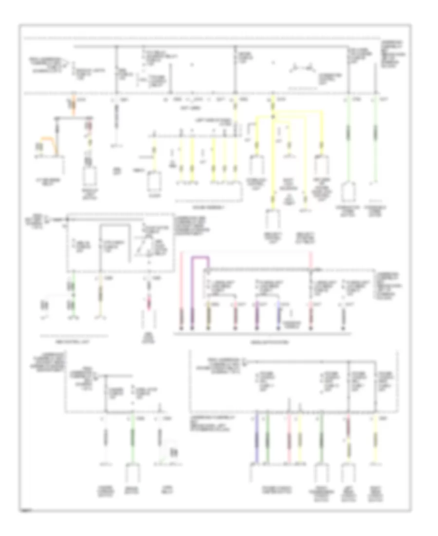
POWER DISTRIBUTION
Power Distribution Wiring Diagram (1 of 3) for Honda CR-V LX 1997
List of elements for Power Distribution Wiring Diagram (1 of 3) for Honda CR-V LX 1997:
- (1997)
- (1997) c
- (1998-01)
- (not used)
- (on right rear corner of engine compartment) underhood fuse/relay box
- (on right rear corner of engine compartment) underhood fuse/relay box
- (option connector)
- 1997-98
- 1998-01
- 20a
- 40a
- A/c compressor clutch relay
- A/t
- Alternator
- Audio unit
- Back up, (radio) fuse 47 7.5a
- Battery
- Battery fuse 41 100a
- Blower motor relay
- C351
- C352
- C418
- C419
- C552
- C751
- C910
- C925
- Canada
- Clock
- Combination light switch
- Condenser fan fuse 56 20a
- Condenser fan relay
- Cooling fan fuse 57
- Data link connector (dlc) (partial)
- Daytime running lights (drl) control unit (canada)
- Door lock unit, roof fuse 51 20a
- Electrical load detector (eld) unit
- Fi e/m fuse 44 15a
- From underhood fuse/relay box fuse 48 (diagram 1 of 3)
- Front ceiling light
- Fuse 1 (not used)
- Hatch glass opener relay
- Hatch glass opener switch
- Headlight fuse 48 30a
- Heater control panel
- Heater motor fuse 55
- Ig1 fuse 42 40a
- Ignition key light
- Ignition key light control unit
- Integrated control unit
- Interior light fuse 43 7.5a
- Interlock unit fuse 33 7.5a
- J/c c433 (behind right kick panel)
- Key interlock switch
- Keyless or power door lock control unit
- Light flasher relay
- Option fuse 54 40a
- Pgm-fi main relay
- Power window fuse 46 40a
- Power window relay
- Powertrain or engine control module (pcm)
- Radiator fan relay
- Rear acc socket fuse 6 10a
- Rear ceiling light
- Rear window defogger relay
- Rr defroster fuse 50 20a
- Running lights fuse 20 10a
- Security control unit
- Security diode
- Security fuse 2 3a
- Security indicator
- Select unlock relay
- Spot- lights
- Starter
- Starter solenoid
- Steering lock
- T101
- T102
- To fuse 11 (diagram 3 of 3)
- To ignition switch (diagram 2 of 3)
- To rear accessory socket relay (diagram 2 of 3)
- To underhood abs fuse/relay box (diagram 3 of 3)
- To underhood fuse/relay box fuse 42 (diagram 1 of 3)
- To underhood fuse/relay box fuse 52 (diagram 3 of 3)
- Underdash fuse/relay box (behind dash, left of steering column)
- W/ anti- theft
- W/o anti- theft
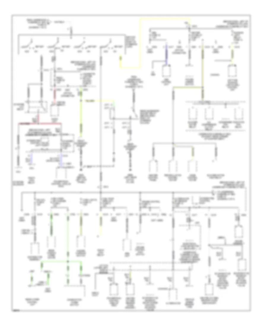
Power Distribution Wiring Diagram (2 of 3) for Honda CR-V LX 1997
List of elements for Power Distribution Wiring Diagram (2 of 3) for Honda CR-V LX 1997:
- (1997-98) (1999-01)
- (1998) (1999-01)
- (a/t)
- (behind dash, left of steering column)
- (behind dash, left of steering column) underdash fuse/relay box
- (canada)
- (m/t)
- (not used)
- (option connector)
- 1998-01
- 1998-01 w/a/t
- 7.5a
- A (1998-01)
- A/c compressor clutch relay
- Abs control unit
- Abs fuse 16 7.5a
- Acc
- Alternator
- Alternator sp sensor fuse 15 7.5a
- Audio unit
- Blower motor high relay
- Blower motor relay
- Bulb chk
- C (1997)
- C352
- C412
- C417
- C418
- C419
- C439
- C502
- C551
- C552
- C752
- C758(b)
- C801
- C913
- C927
- C928
- Canada
- Cigarette lighter fr acc socket fuse 27 10a
- Coil
- Combination wiper switch
- Condenser fan relay
- Cruise control fuse 14 7.5a
- Cruise control main switch
- Daytime running lights (drl) control unit
- Distributor assembly
- Electrical load detector (eld) unit
- Evaporative emission (evap) by-pass solenoid valve
- Evaporative emission (evap) control canister vent shut valve
- Evaporative emission (evap) purge control solenoid valve
- From underdash fuse/relay box fuse 6 (diagram 1 of 3)
- From underhood fuse/relay box e fuse 42 (diagram 1 of 3)
- Front accessory socket
- Fuel pump (srs unit) fuse 13 15a
- G200 (behind left kick panel)
- G999 (left rear hatch pillar)
- Gauge assembly
- Hazard warning switch
- Heated oxygen sensor (ho2s) (primary)
- Heated oxygen sensor (ho2s) (secondary)
- Heater a/c relay fuse 17 7.5a
- Heater control panel
- Ign coil fuse 9 15a
- Ignition switch (part of steering lock)
- Integrated control unit
- J/c c134 (lower left side of engine)
- Lock
- Mode control motor
- Pgm-fi main relay
- Power mirror switch
- Powertrain control module (pcm)
- Radiator fan relay
- Radio fuse 28 10a
- Rear accessory socket
- Rear accessory socket relay (behind dash, right of steering column)
- Rear window wiper motor
- Rear wiper control unit
- Recirculation control motor
- Rr wiper rr washer fuse 3 10a
- Running light relay fuse 18
- Srs unit
- Start
- Starter cut relay
- Starter signal fuse 31 7.5a
- Starter solenoid
- To underdash fuse/relay box fuse 19 (diagram 3 of 3)
- Turn lights fuse 12 7.5a
- Underdash fuse/relay box
- Underhood fuse/relay box (on right rear corner of compartment)
- Underhood fuse/relay box (on right rear corner of engine compartment)
- Usa
- Vehicle speed sensor (vss)
- W/ abs
Power Distribution Wiring Diagram (3 of 3) for Honda CR-V LX 1997
List of elements for Power Distribution Wiring Diagram (3 of 3) for Honda CR-V LX 1997:
- (left side of dash) j/c 508
- (not used)
- (power window relay) (diagram 1 of 3)
- 1998-01
- A/t
- A/t reverse relay
- Abs +b fuse 62 20a
- Abs control unit
- Abs pump motor
- Abs pump motor relay
- Back-up light switch
- Backup lights fuse 19 7.5a
- Brake switch
- C352
- C353
- C359
- C360
- C417
- C418
- C419
- C502
- C551
- C751
- C752
- C801
- Canadian models
- Clock
- Coil
- Combination wiper switch
- Fr wiper fr washer fuse 26 20a
- From battery (diagram 1 of 3)
- From underdash fuse/relay box d
- From underdash fuse/relay box g fuse 15 (diagram 2 of 3)
- From underhood fuse/relay b box (diagram 1 of 3)
- Front passenger's window switch
- Gauge assembly
- Hazard fuse 53 10a
- Hazard warning switch
- Headlights system
- Horn relay
- Horn, stop fuse 52 15a
- Integrated control unit
- Interlock control unit
- Keyless or power door lock control unit
- L headlight high beam fuse 5 10a
- L headlight low beam fuse 22 10a
- Left rear window switch
- M/t
- Meter fuse 25 7.5a
- Mtr check fuse 63 7.5a
- Nca
- P/w relay (sunroof relay) fuse 24 7.5a
- Pnk
- Power window fr-l fuse 11 20a
- Power window fr-r fuse 10 20a
- Power window master switch
- Power window relay
- Power window rr-l fuse 7 20a
- Power window rr-r fuse 8 20a
- Pump motor fuse 61 40a
- R headlight high beam fuse 4 10a
- R headlight low beam fuse 21 10a
- Right rear window switch
- Security control unit
- Security starter cut relay
- Shift lock solenoid
- Srs fuse 23 10a
- Srs unit
- Underdash fuse/relay box (behind dash, left of steering column)
- Underhood abs fuse/relay box (on right rear corner of engine compartment)
- Underhood fuse/relay box (on right rear corner of engine compartment)
- W/ abs
- W/ anti- theft
- Windshield wiper motor
POWER DOOR LOCKS
Power Door Lock Wiring Diagram for Honda CR-V LX 1997
List of elements for Power Door Lock Wiring Diagram for Honda CR-V LX 1997:
- (behind left kick panel) (w/ anti-theft) select unlock relay
- Battery input
- C351
- C419
- Ceiling light
- Door sw input
- Driver's door lock actuator
- Driver's door lock switch
- Front passenger's door lock actuator
- Fuse 25 meter 7.5a
- Fuse 51 door lock unit, roof 20a
- G200 (behind left kick panel)
- G200 (left kick panel)
- Ground
- Hatch glass
- Horn rly cntl
- Horns system
- Hot at all times
- Hot in on or start
- Ign key input
- Ignition input
- Ignition key switch
- Interior lights system
- Interior lights system (door switches)
- J/c c433 (behind right kick panel)
- Key sw input
- Keyless or power door lock control unit (in driver's door)
- Left rear door lock actuator
- Lock input
- Lock output
- Red
- Right rear door lock actuator
- Security control unit (w/ anti-theft) (behind left kick panel)
- Select unlock
- Steering lock
- Trunk,tailgate, fuel doors system (releases)
- Underdash fuse/relay box (behind dash, left of steering column)
- Underhood fuse/relay box (on right rear corner of engine compartment)
- Unlk/lock ctrl
- Unlock input
- Unlock output
- W/ anti- theft
- W/ anti-theft
- W/0 anti- theft
- W/o anti-theft
- Warning system
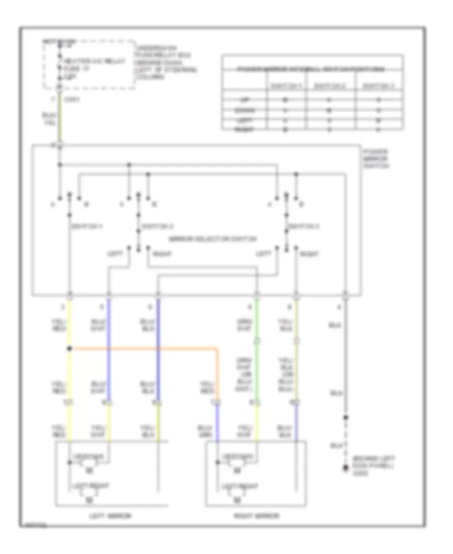
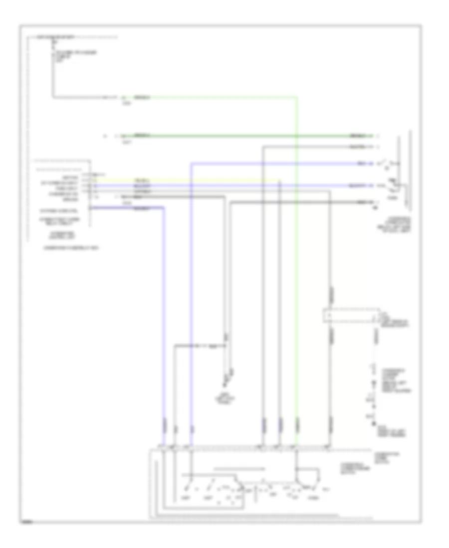
POWER MIRRORS
Power Mirror Wiring Diagram for Honda CR-V LX 1997
List of elements for Power Mirror Wiring Diagram for Honda CR-V LX 1997:
- (behind left kick panel) g202
- C551
- Down
- Heater a/c relay fuse 17 7.5a
- Hot in on
- Left
- Left mirror
- Left/right
- Mirror selector switch
- Power mirror internal switch positions
- Power mirror switch
- Right
- Right mirror
- Switch 1
- Switch 2
- Switch 3
- Underdash fuse/relay box (behind dash, left of steering column)
- Up/down
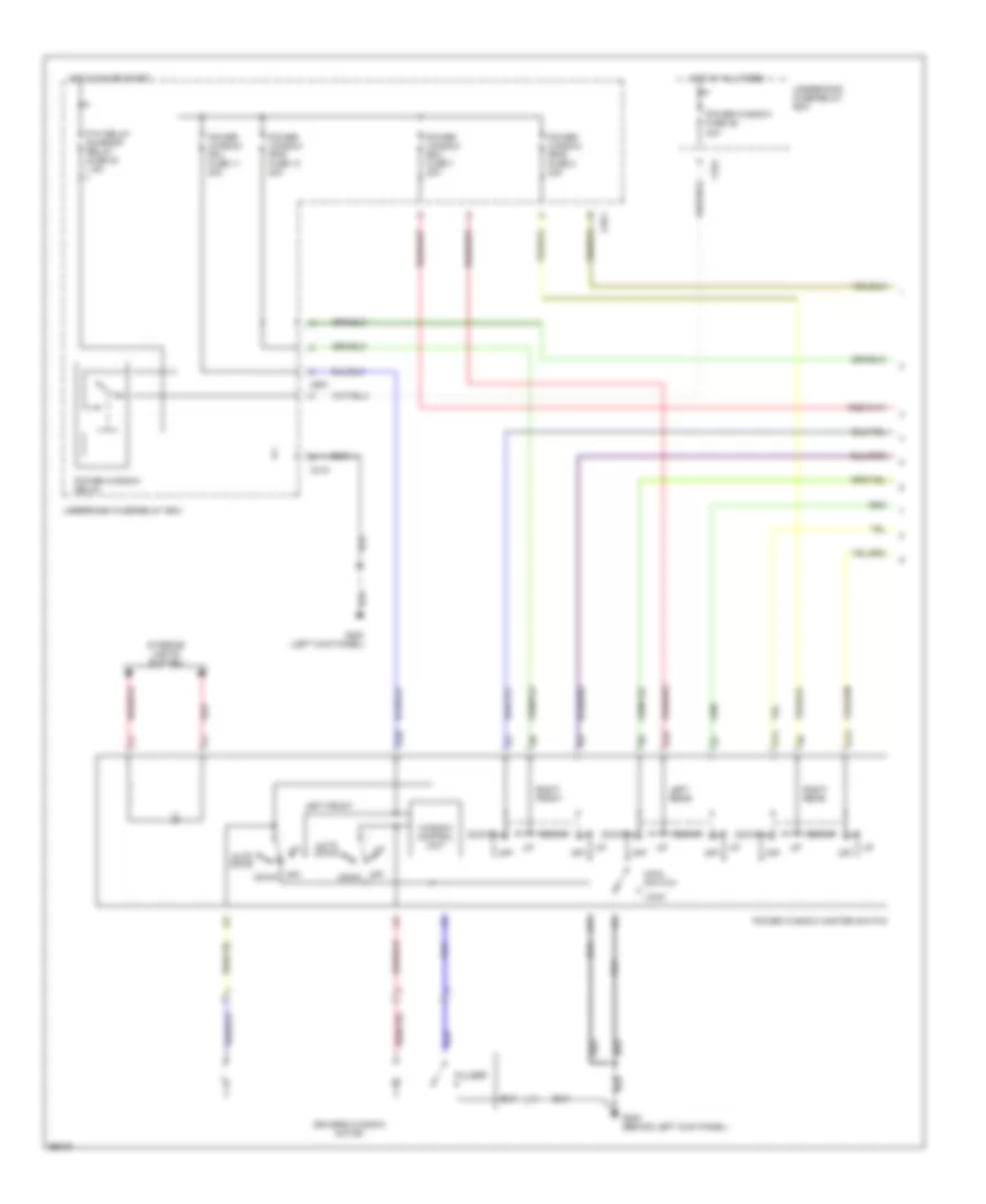
POWER WINDOWS
Power Window Wiring Diagram (1 of 2) for Honda CR-V LX 1997
List of elements for Power Window Wiring Diagram (1 of 2) for Honda CR-V LX 1997:
- 40a
- A10
- A11
- A12
- A13
- A14
- Auto down
- C351
- C418
- C551
- Down
- Driver's window motor
- G200 (behind left kick panel)
- G200 (left kick panel)
- Hot at all times
- Hot in on or start
- Interior lights system
- Left front
- Left rear
- Lock
- Main switch
- Off
- P/w relay sunroof relay fuse 24 7.5a
- Power window fr-l fuse 11 20a
- Power window fr-r fuse 10 20a
- Power window fuse 46
- Power window master switch
- Power window relay
- Power window rr-l fuse 7 20a
- Power window rr-r fuse 8 20a
- Pulser
- Red
- Right front
- Right rear
- Underdash fuse/relay box
- Underhood fuse/relay box
- Window control unit
Power Window Wiring Diagram (2 of 2) for Honda CR-V LX 1997
List of elements for Power Window Wiring Diagram (2 of 2) for Honda CR-V LX 1997:
- Down
- Front passenger's window motor
- Front passenger's window switch
- Left rear window motor
- Left rear window switch
- Off
- Right rear window motor
- Right rear window switch
RADIO
Radio Wiring Diagrams for Honda CR-V LX 1997
List of elements for Radio Wiring Diagrams for Honda CR-V LX 1997:
- (behind front console) g206
- (option connector)
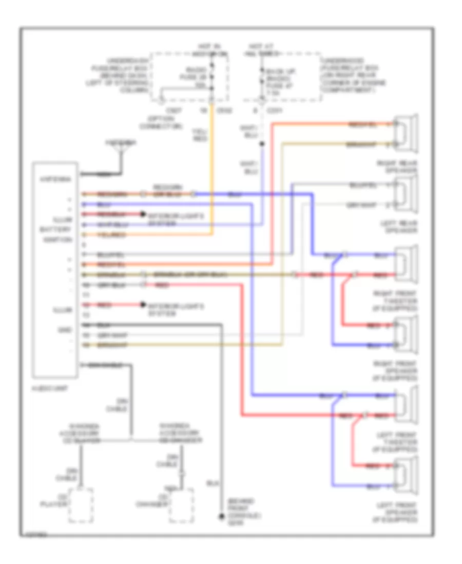
- Antenna
- Audio unit
- Back up, (radio) fuse 47 7.5a
- Battery
- C351
- C502
- C927
- Cd changer
- Cd player
- Din cable
- Gnd
- Hot at all times
- Hot in acc or on
- Ignition
- Illum
- Interior lights system
- Left front speaker (if equipped)
- Left front tweeter (if equipped)
- Left rear speaker
- Nca
- Radio fuse 28 10a
- Red
- Right front speaker (if equipped)
- Right front tweeter (if equipped)
- Right rear speaker
- Underdash fuse/relay box (behind dash, left of steering column)
- Underhood fuse/relay box (on right rear corner of engine compartment)
- W/honda accessory cd changer
- W/honda accessory cd player
SHIFT INTERLOCKS
Shift Interlock Wiring Diagram for Honda CR-V LX 1997
List of elements for Shift Interlock Wiring Diagram for Honda CR-V LX 1997:
- (1997)
- (1998)
- (behind dash, right of steering column)
- (on left side of throttle body)
- (on lower rear of transaxle)
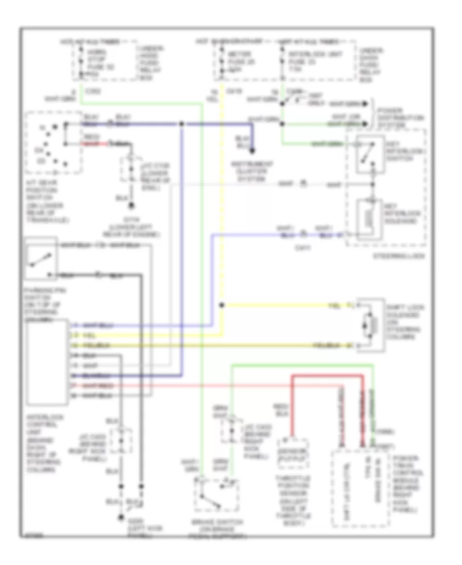
- A/t gear position switch
- A28
- A32
- B12
- Brake sw in
- Brake switch (on brake pedal support)
- C27
- C352
- C411
- C418
- C419
- G114 (lower left rear of engine)
- G200 (left kick panel)
- Horn, stop fuse 52 15a
- Hot at all times
- Hot in on or start
- Instrument cluster system
- Interlock control unit
- Interlock unit fuse 33 7.5a
- J/c c136 (lower rear of eng.)
- J/c c433 (behind right kick panel)
- Key interlock solenoid
- Key interlock switch
- Meter fuse 25 7.5a
- Only
- Parking pin switch (on top of steering column)
- Power distribution system
- Power- train control module (behind right kick panel)
- Sensor putput
- Shft lk cir ctrl
- Shift lock solenoid (on steering column)
- Steering lock
- Throttle position sensor
- Tps in
- Under- dash fuse/ relay box
- Under- hood fuse/ relay box
STARTING/CHARGING
Charging Wiring Diagram for Honda CR-V LX 1997
List of elements for Charging Wiring Diagram for Honda CR-V LX 1997:
- (canada)
- (starter solenoid)
- (under-hood abs fuse/relay box)
- (usa)
- A19
- Alt fr sig
- Alt output sig
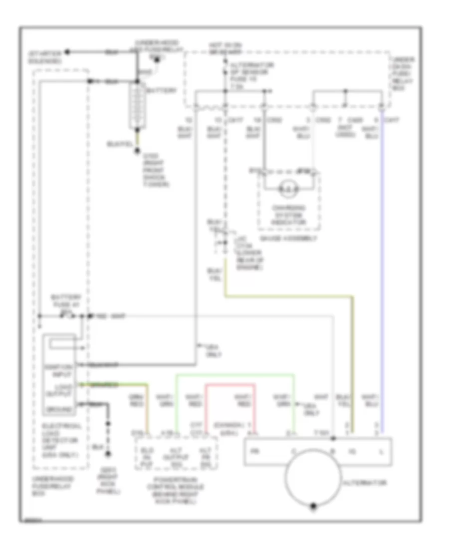
- Alternator
- Alternator sp sensor fuse 15 7.5a
- B15
- B16
- Battery
- Battery fuse 41 80a
- C17
- C417
- C420 (not used)
- C502
- Charging system indicator
- D16
- Eld in- put
- Electrical load detector unit (usa only)
- G103 (right front shock tower)
- G203 (right kick panel)
- Gauge assembly
- Ground
- Hot in on or start
- Ignition input
- J/c c134 (lower rear of engine)
- Load output
- Powertrain control module (behind right kick panel)
- T101
- T102
- Under dash- fuse/ relay box
- Under-hood fuse/relay box
- Usa only
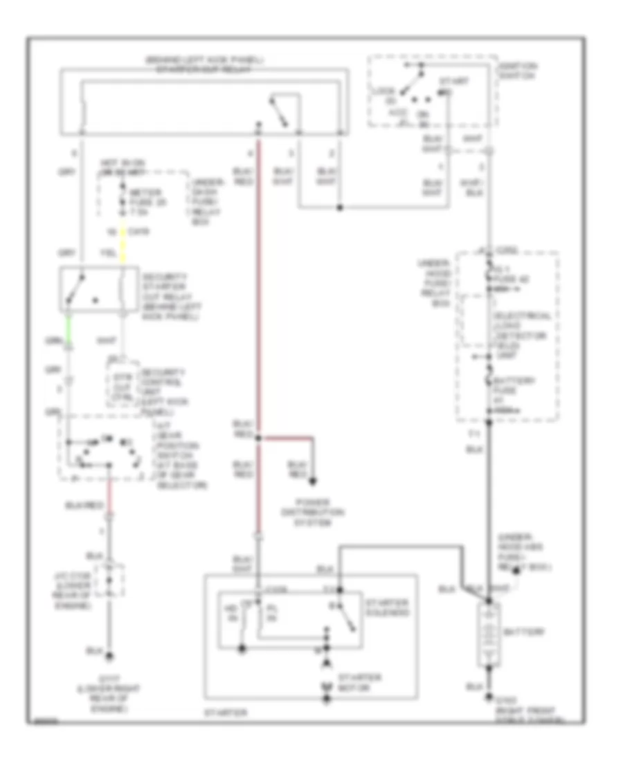
Starting Wiring Diagram, with Anti-theft for Honda CR-V LX 1997
List of elements for Starting Wiring Diagram, with Anti-theft for Honda CR-V LX 1997:
- (behind left kick panel) starter cut relay
- (under- hood abs fuse/- relay box)
- A/t gear position switch (at base of gear selector)
- Acc (i)
- Battery
- Battery fuse 100a
- C129
- C352
- C419
- Electrical load detector (eld) unit
- G103 (right front strut tower)
- G117 (lower right rear of engine)
- Hd in
- Hot in on or start
- Ig 1 fuse 42 40a
- Ignition switch
- J/c c136 (lower rear of engine)
- Lock (0)
- Meter fuse 25 7.5a
- On (ii)
- Pl in
- Power distribution system
- Security control unit (left kick panel)
- Security starter cut relay (behind left kick panel)
- Start (iii)
- Starter
- Starter motor
- Starter solenoid
- Str cut ctrl
- Under- dash fuse/ relay box
- Under- hood fuse/ relay box
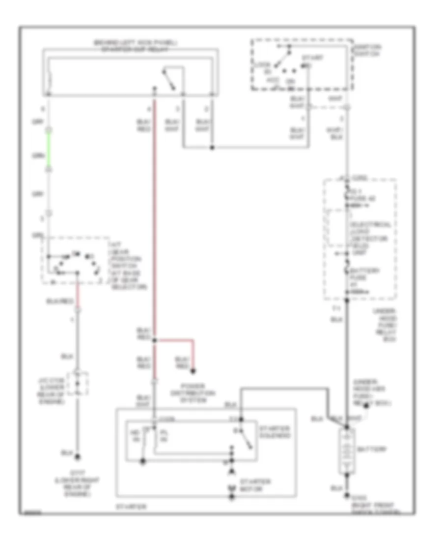
Starting Wiring Diagram, without Anti-theft for Honda CR-V LX 1997
List of elements for Starting Wiring Diagram, without Anti-theft for Honda CR-V LX 1997:
- (behind left kick panel) starter cut relay
- (under- hood abs fuse/- relay box)
- A/t gear position switch (at base of gear selector)
- Acc (i)
- Battery
- Battery fuse 100a
- C129
- C352
- Electrical load detector (eld) unit
- G103 (right front shock tower)
- G117 (lower right rear of engine)
- Hd in
- Ig 1 fuse 42 40a
- Ignition switch
- J/c c136 (lower rear of engine)
- Lock (0)
- On (ii)
- Pl in
- Power distribution system
- Start (iii)
- Starter
- Starter motor
- Starter solenoid
- Under- hood fuse/ relay box
SUPPLEMENTAL RESTRAINTS
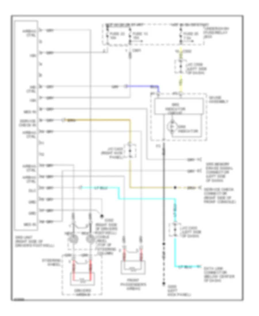
Supplemental Restraint Wiring Diagram for Honda CR-V LX 1997
List of elements for Supplemental Restraint Wiring Diagram for Honda CR-V LX 1997:
- (right side of driver's footwell) cable reel (top of steering column)
- Airbag ctrl
- C502
- C801
- Data link connector (below center of dash)
- Dlc
- Driver's airbag
- Front passenger's airbag
- Fuse 13 15a
- Fuse 23 10a
- Fuse 25 7.5a
- G200 (left kick panel)
- G302
- Gauge assembly
- Grd
- Hot in on or start
- Ign
- Ind ctrl
- J/c c433 (left side of dash)
- J/c c433 (right kick panel)
- J/c c508 (left side of dash)
- Mes in
- Nca
- Red
- Service check connector (right side of front console)
- Service check in
- Srs indicator
- Srs indicator circuit
- Srs memory erase signal connector (left side of dash)
- Srs unit (right side of driver's footwell)
- Steering wheel
- Under-dash fuse/relay box
TRANSMISSION
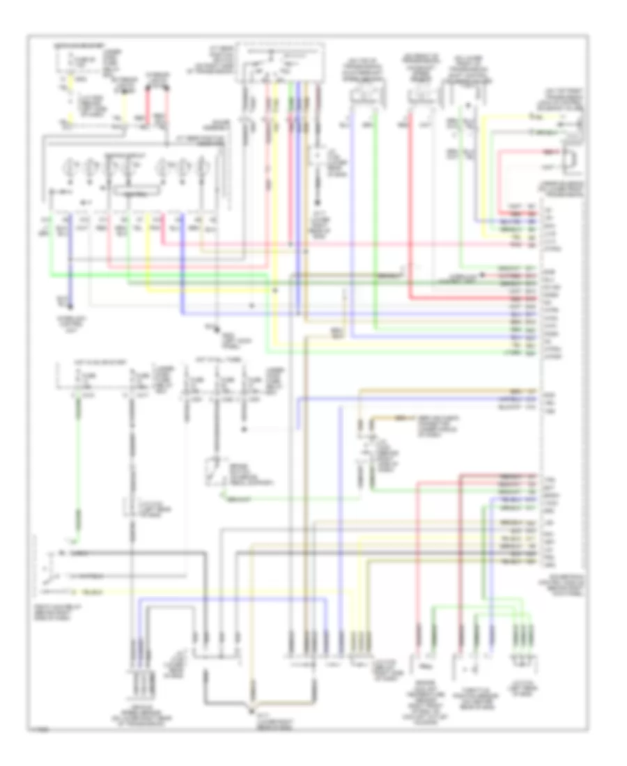
A/T Wiring Diagram for Honda CR-V LX 1997
List of elements for A/T Wiring Diagram for Honda CR-V LX 1997:
- (j/c c508 (behind left side of dash)
- (on front of transmission)
- (on lower front of transmission) shift control solenoid valves
- (on top front transmission) lock-up control solenoid valves
- (on top of transmission)
- A/t gear position indicator
- A/t gear position switch (on right side of transmission)
- A10
- A11
- A12
- A13
- A14
- A22
- A23
- A24
- Atp1
- Atp2
- Atpd3
- Atpd4
- Atpnp
- Atpr
- B11
- B12
- B13
- B14
- B15
- B16
- B17
- B18
- B22
- B23
- B24
- B25
- Bksw
- Brake switch (on brake pedal support)
- C10
- C18
- C351
- C352
- C417
- C418
- C502
- Control
- Control unit
- Countershaft speed sensor
- D10
- D11
- D4 ind
- Dimming circuit
- Ect
- Engine coolant temperature sensor (right front of eng, on coolant outlet housing)
- Exterior lights system
- Fuse 15a
- Fuse 25 7.5a
- Fuse 7.5a
- G117 (lower right rear of eng)
- G200 (left kock panel)
- Gauge assembly
- Ground
- Hot at all times
- Hot in on or start
- Ignition
- Igp1
- Igp2
- Interior lights system
- Interlock
- Interlock control unit
- J/c c122 (below right side of dash)
- J/c c134 (left rear of eng)
- J/c c136 (lower rear of eng)
- J/c c433 (behind right side of dash)
- Lc a
- Lc b
- Lg1
- Lg2
- Linear solenoid (on lower front transmission)
- Ls+
- Ls-
- Mainshaft speed sensor
- Ncsg
- Nmsg
- Pg1
- Pg2
- Pgm-fi main relay (behind right side of dash)
- Pnk
- Powertrain control module (behind right kick panel)
- Red
- Scs
- Service check connector (under middle of dash)
- Sg2
- Sha
- Shb
- Slu
- Throttle position sensor (on center rear of eng)
- Tps
- Under- dash fuse/ relay box
- Under- hood fuse/ relay box
- Vbu
- Vcc2
- Vehicle speed sensor (on lower right rear of transmission)
- Vss
- Vss out
TRUNK, TAILGATE, FUEL DOOR
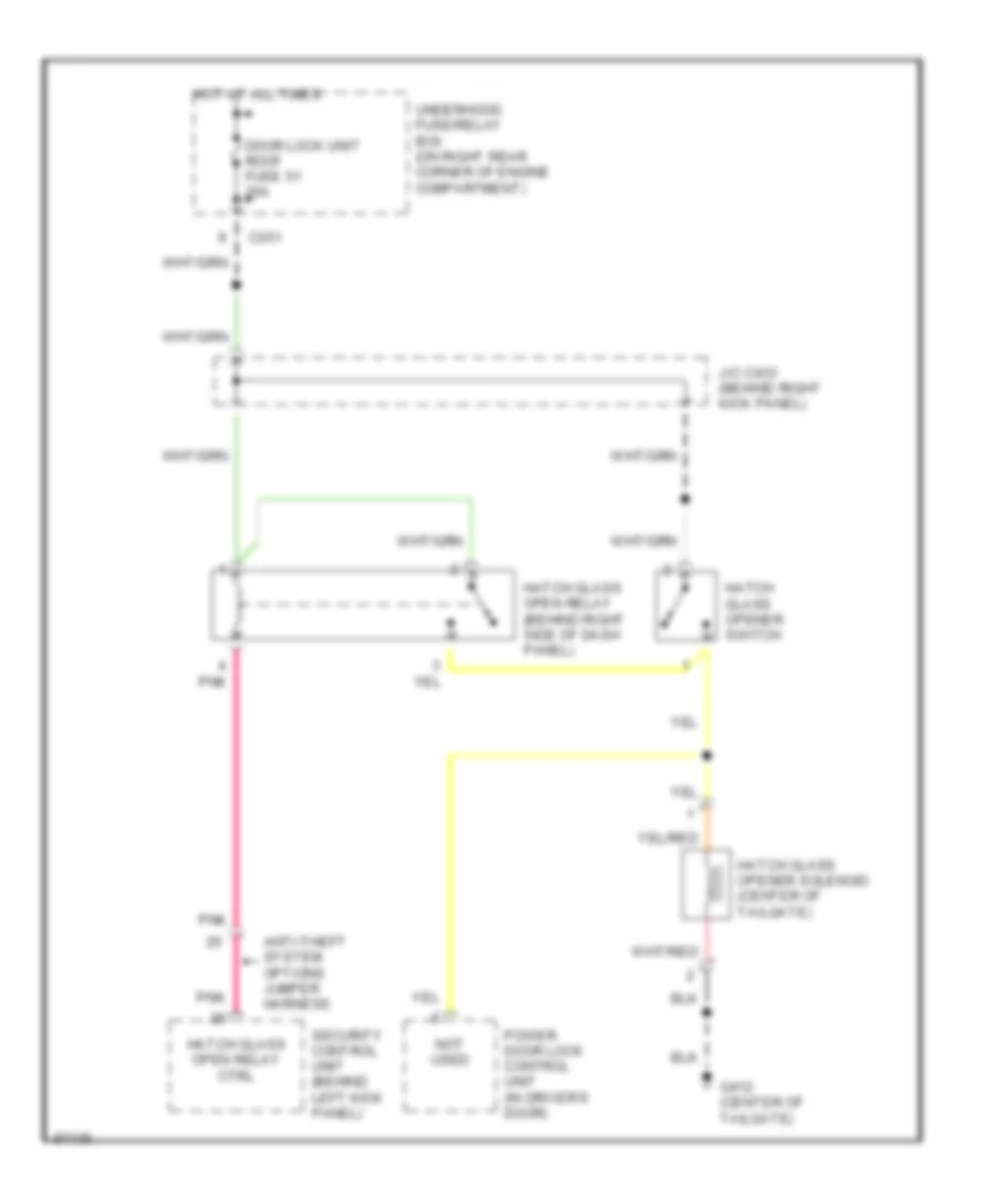
Liftglass Release Wiring Diagram, with Security for Honda CR-V LX 1997
List of elements for Liftglass Release Wiring Diagram, with Security for Honda CR-V LX 1997:
- Anti-theft system options jumper harness
- C351
- Door lock unit roof fuse 51 20a
- G412 (center of tailgate)
- Hatch glass open relay (behind right side of dash panel)
- Hatch glass open relay ctrl
- Hatch glass opener solenoid (center of tailgate)
- Hatch glass opener switch
- Hot at all times
- J/c c433 (behind right kick panel)
- Not used
- Pnk
- Power door lock control unit (in driver's door)
- Security control unit (behind left kick panel)
- Underhood fuse/relay box (on right rear corner of engine compartment)
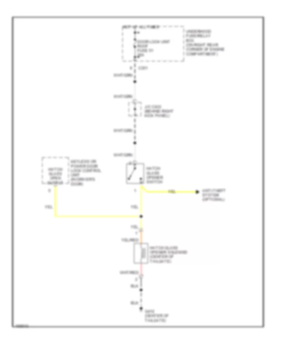
Liftglass Release Wiring Diagram, without Security for Honda CR-V LX 1997
List of elements for Liftglass Release Wiring Diagram, without Security for Honda CR-V LX 1997:
- Anti-theft system (optional)
- C351
- Door lock unit roof fuse 51 20a
- G412 (center of tailgate)
- Hatch glass open output
- Hatch glass opener solenoid (center of tailgate)
- Hatch glass opener switch
- Hot at all times
- J/c c433 (behind right kick panel)
- Keyless or power door lock control unit (in driver's door)
- Underhood fuse/relay box (on right rear corner of engine compartment)
WARNING SYSTEMS
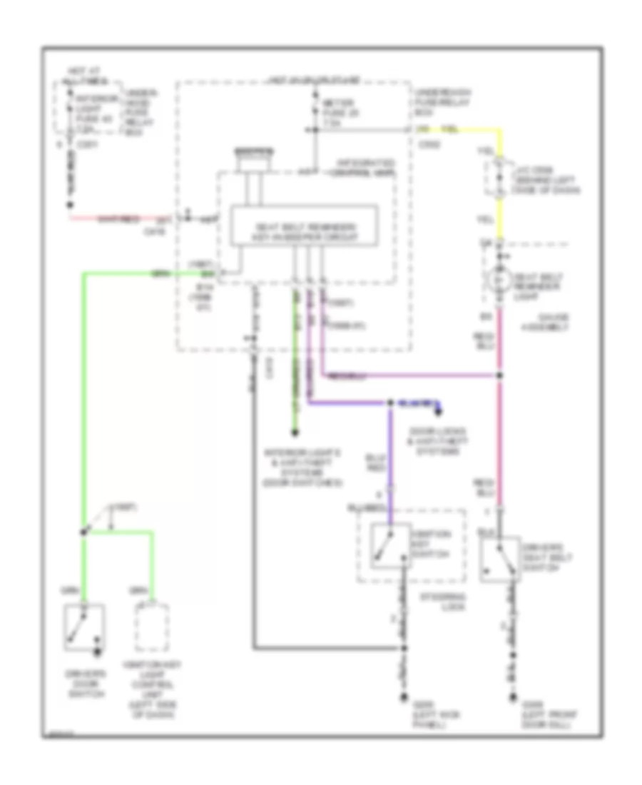
Warning System Wiring Diagrams for Honda CR-V LX 1997
List of elements for Warning System Wiring Diagrams for Honda CR-V LX 1997:
- (1997)
- (1997) b9
- (1998 -01)
- A14
- B10
- B13
- B14
- B2 (1998-01)
- B7 (1997)
- Beeper
- C351
- C418
- C502
- Door locks & anti-theft systems
- Driver's door switch
- Driver's seat belt switch
- G200 (left kick panel)
- G309 (left front door sill)
- Gauge assembly
- Hot at all times
- Hot in on or start
- Ignition key light control unit (left side of dash)
- Ignition key switch
- Integrated control unit
- Interior light fuse 43 7.5a
- Interior lights & anti-theft systems (door switches)
- J/c c508 (behind left side of dash)
- Meter fuse 25 7.5a
- Seat belt reminder light
- Seat belt reminder/ key-in beeper circuit
- Steering lock
- Under- hood fuse relay box
- Underdash fuse/relay box
WIPER/WASHER
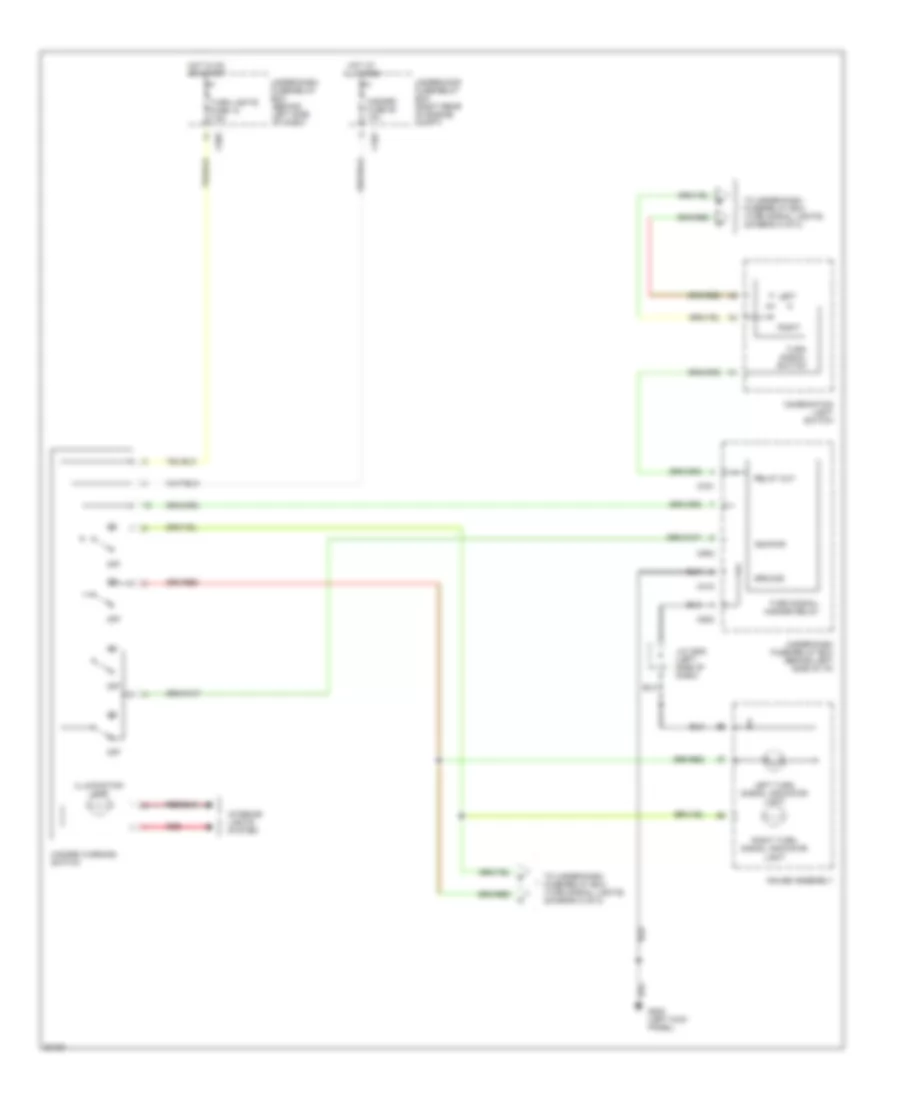
Front Wiper/Washer Wiring Diagram for Honda CR-V LX 1997
List of elements for Front Wiper/Washer Wiring Diagram for Honda CR-V LX 1997:
- C417
- C418
- C751
- Combination wiper switch
- Fr wiper, fr washer fuse 26 20a
- G100 (front of left front fender)
- G200 (left kick panel)
- Ground
- Hot in on or start
- Ignition
- Int
- Int wiper on input
- Int/park wipe ctrl
- Integrated control unit
- Intermittent wiper relay circuit
- J/c c433 (left rear of engine compt)
- Mist
- Off
- Park
- Park input
- Run
- Under-dash fuse/relay box
- Wash
- Washer sw on
- Windshield washer motor (behind left side of front bumper)
- Windshield wiper motor (below left side of cowl vent)
- Windshield wiper/washer switch
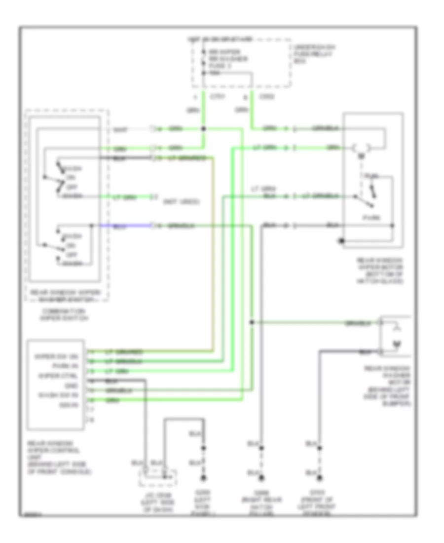
Rear Wiper/Washer Wiring Diagram for Honda CR-V LX 1997
List of elements for Rear Wiper/Washer Wiring Diagram for Honda CR-V LX 1997:
- (not used)
- C552
- C751
- Combination wiper switch
- G100 (front of left front fender)
- G200 (left kick panel)
- G998 (right rear hatch pillar)
- Gnd
- Hot in on or start
- Ign in
- J/c c508 (left side of dash)
- Off
- Park
- Park in
- Rear window washer motor (behind left side of front bumper)
- Rear window wiper control unit (behind left side of front console)
- Rear window wiper motor (bottom of hatch glass)
- Rear window wiper/ washer switch
- Rr wiper rr washer fuse 3 10a
- Run
- Under-dash fuse/relay box
- Wash
- Wash sw in
- Wiper ctrl
- Wiper sw on

 Čeština
 Dansk
Dansk Deutsch
 Ελληνικά
 English
 Español
 Suomi
Suomi Français
 Français
 עברית
עברית Hrvatski
 Magyar
 Italiano
 日本語
日本語 한국어
한국어 Nederlands
 Polski
 Português
 Português
 Română
 Русский
 Slovenčina
 Slovenščina
 Svenska
 Türkçe
 中文 (中国)