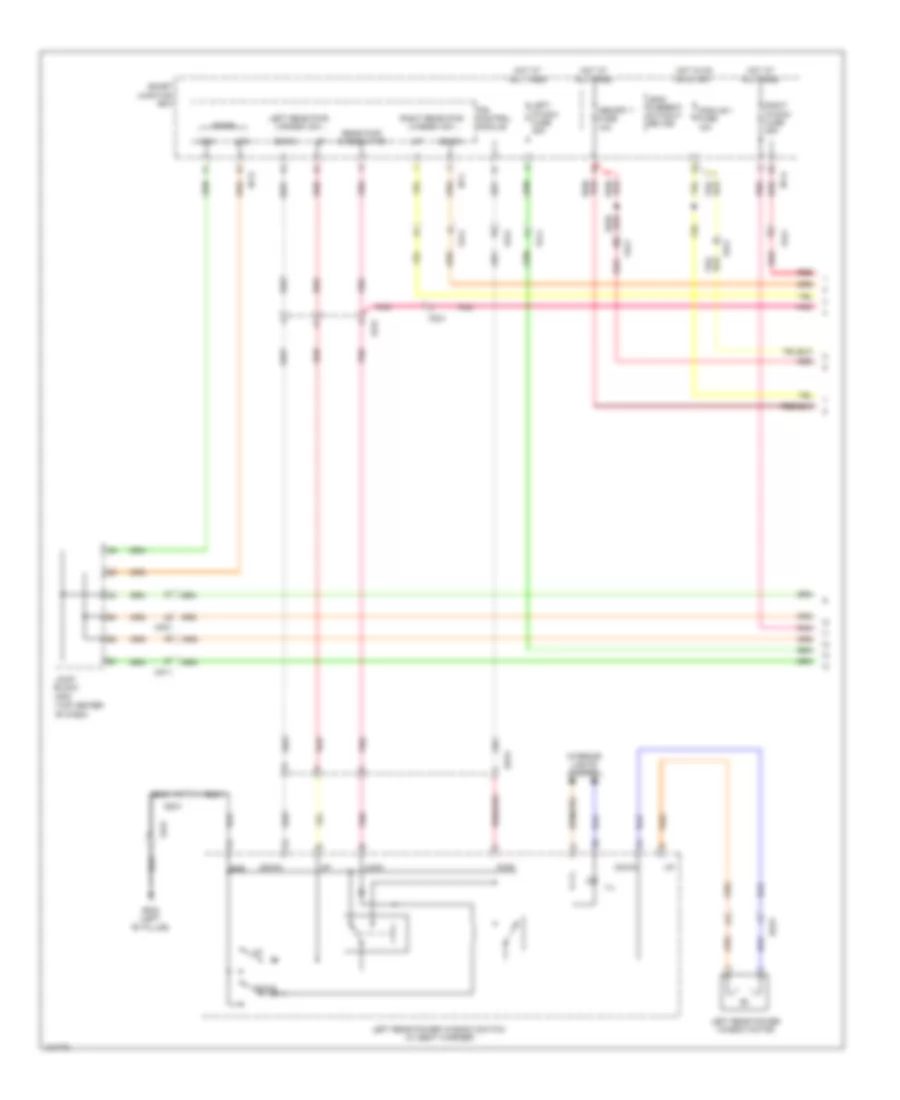
AIR CONDITIONING
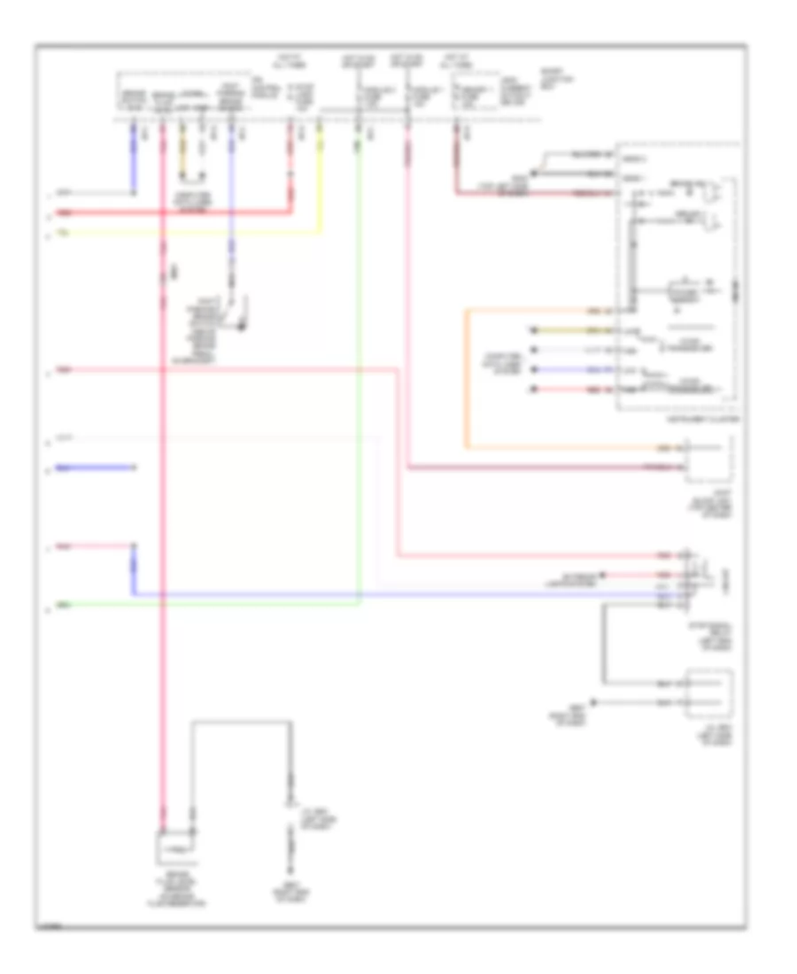
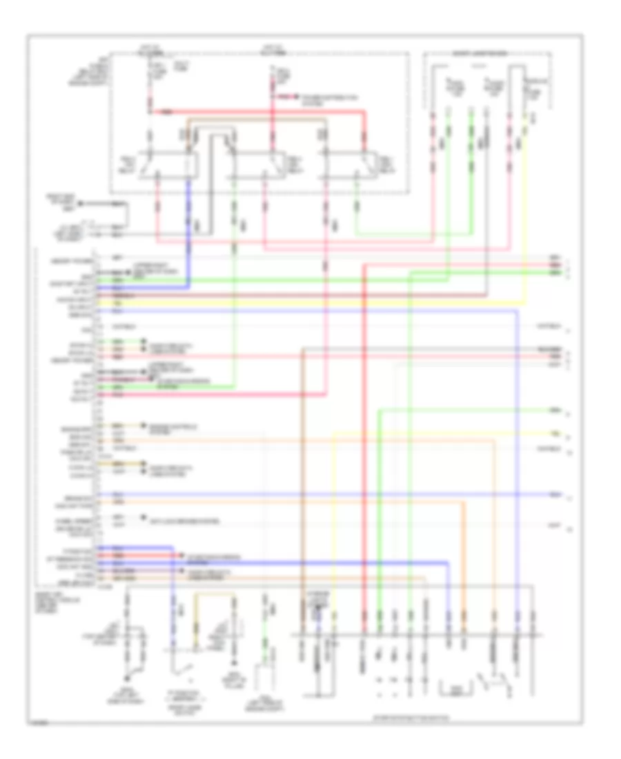
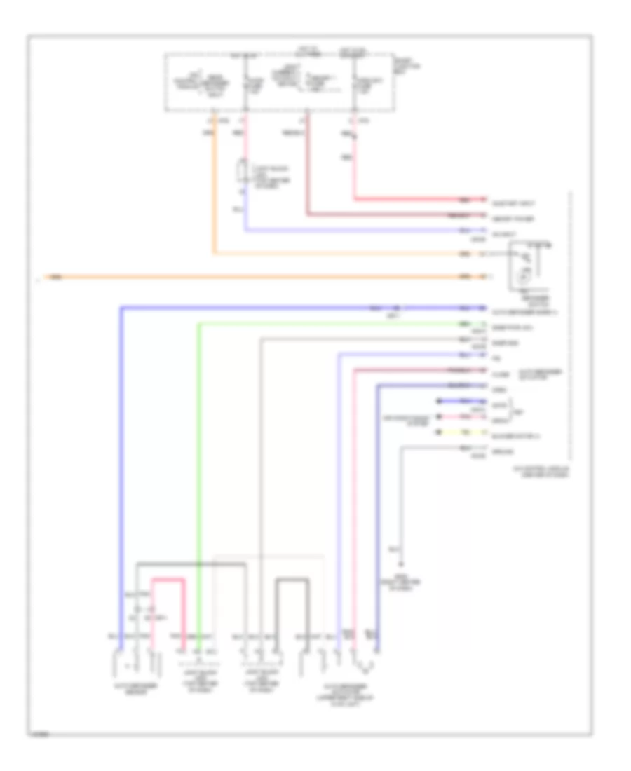
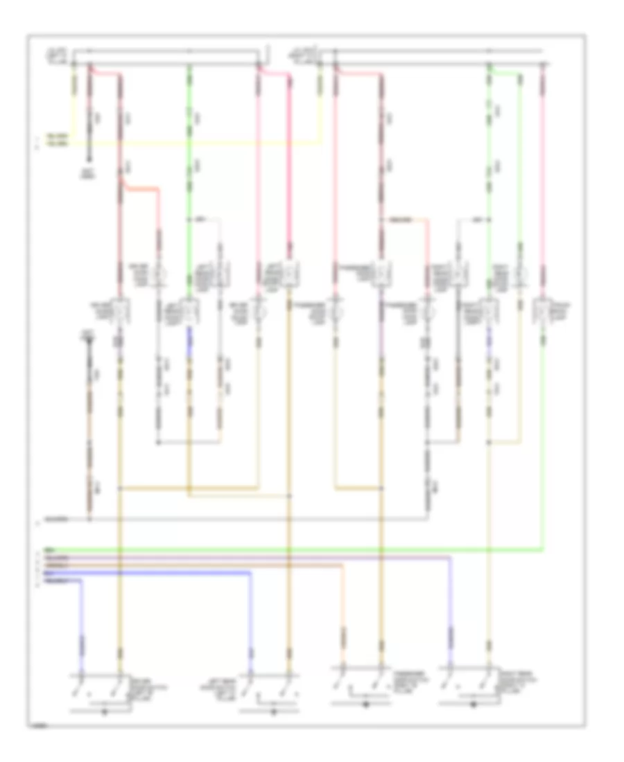
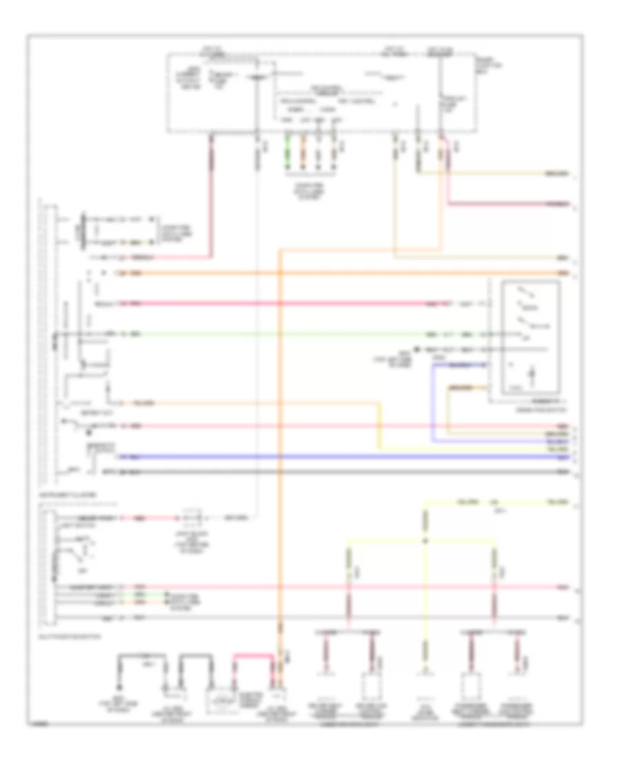
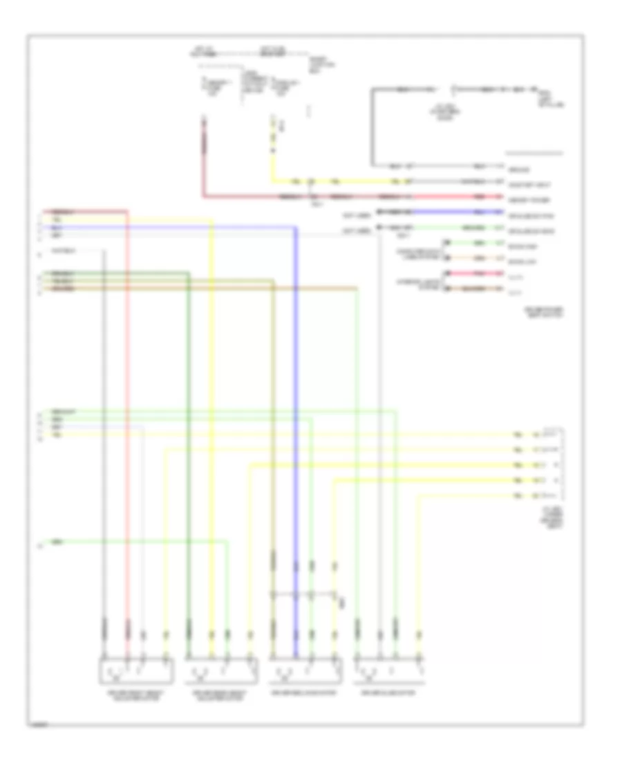
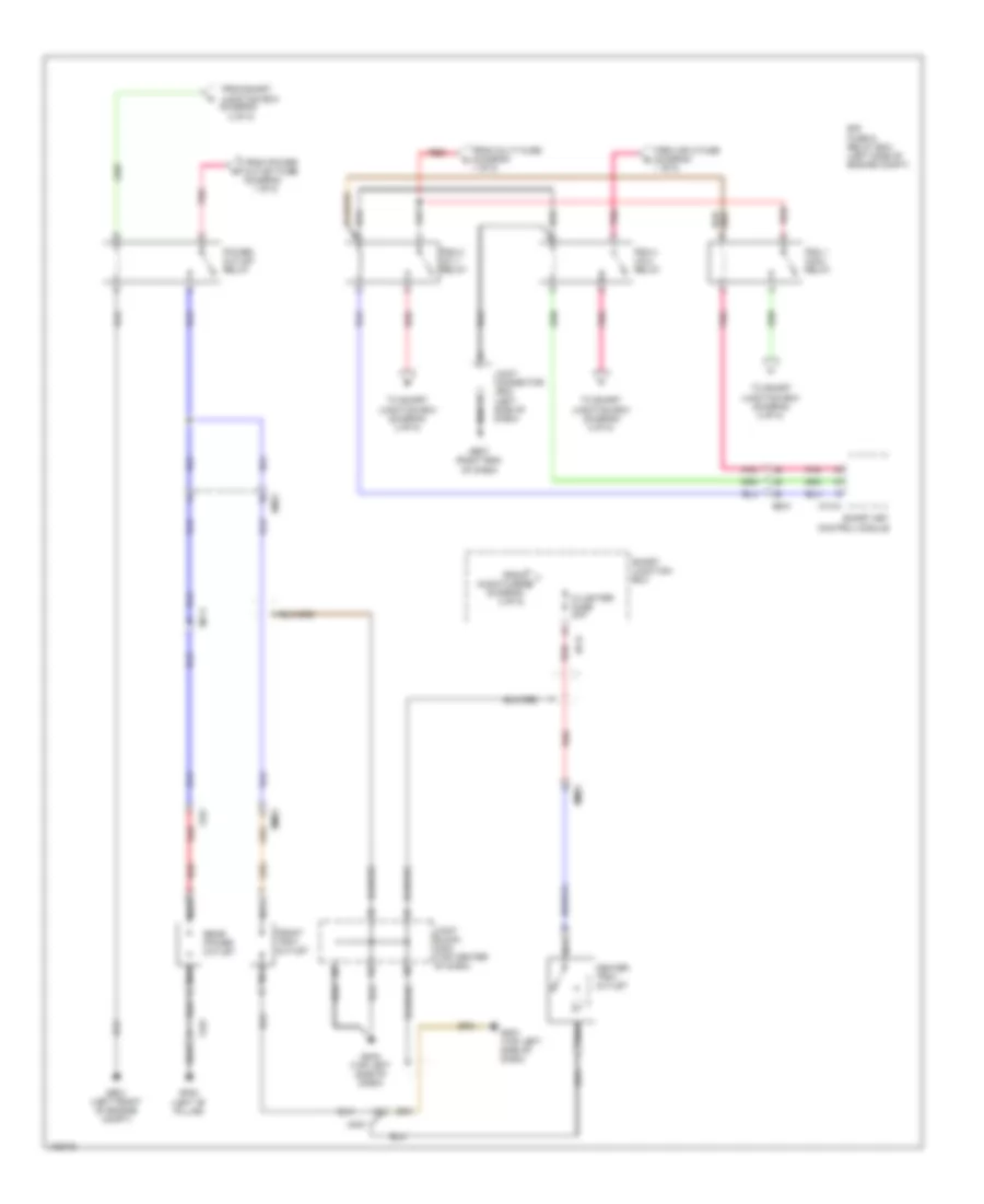
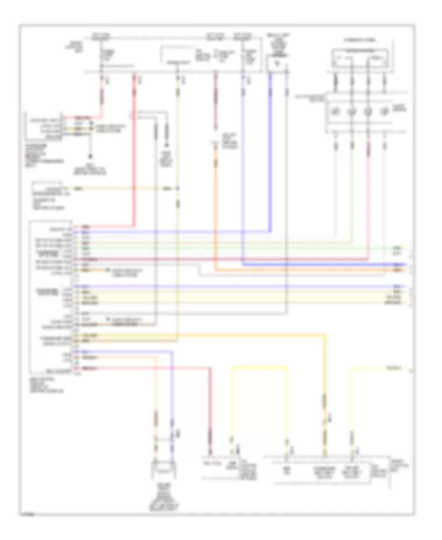
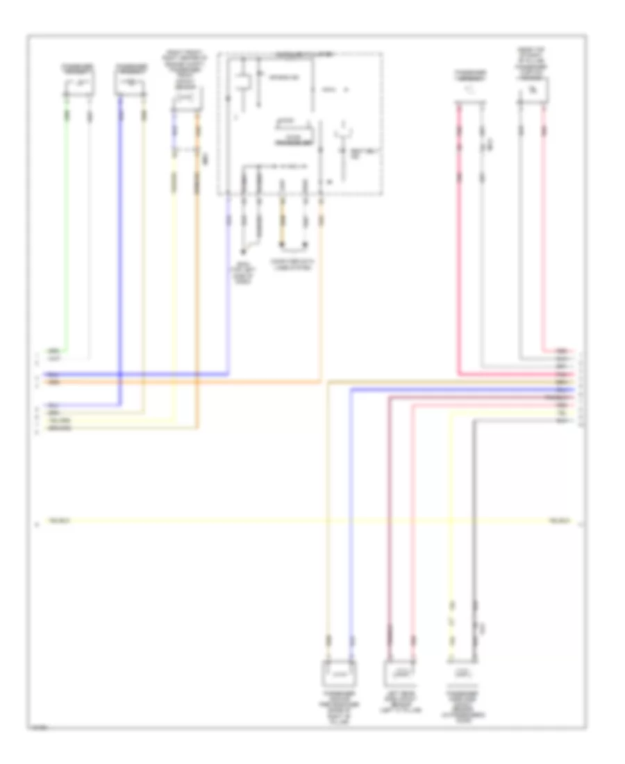
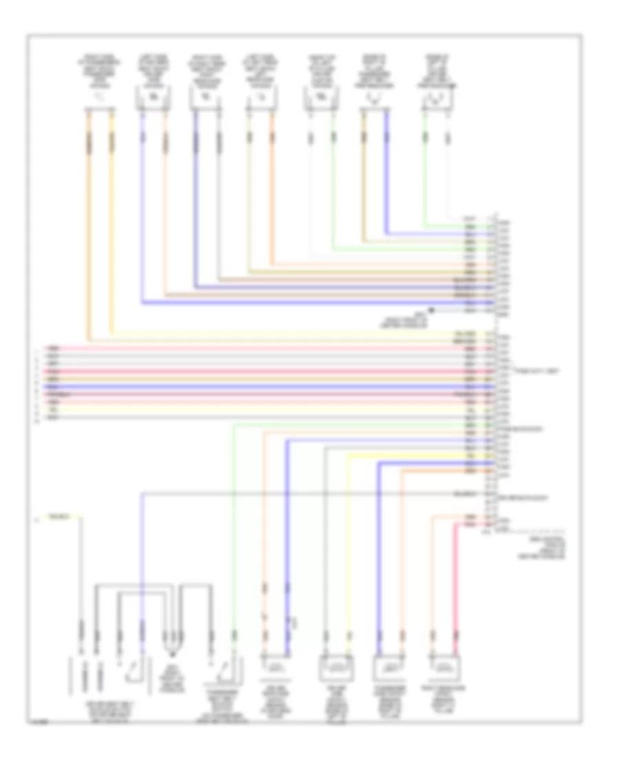
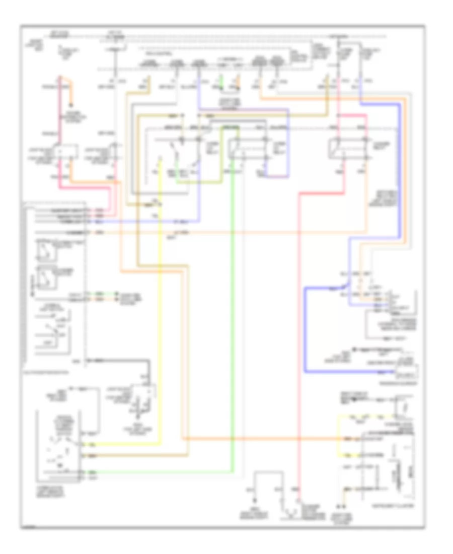
Automatic A/C Wiring Diagram (1 of 2) for Hyundai Azera 2014
 https://portal-diagnostov.com/license.html
Automotive Electricians Portal FZCO
Automotive Electricians Portal FZCO
https://portal-diagnostov.com/license.html
https://portal-diagnostov.com/license.html
Automotive Electricians Portal FZCO
Automotive Electricians Portal FZCO
List of elements for Automatic A/C Wiring Diagram (1 of 2) for Hyundai Azera 2014:
- (left side of dash) j/c je03
- A/bag fuse 15a
- A/c control module (center of dash)
- A/con fuse 10a
- A/con fuse 7.5a
- Active incar sensor (center of dash)
- Ambient temperature sensor (center front of radiator)
- Blower fuse 40a
- Blower motor (+)
- Blower motor (under right side of dash)
- Blower relay
- C-can hi
- C-can lo
- Clean sig
- Cluster ionizer (left side of hvac blower housing)
- Computer data lines system
- Defog snsr f/b
- Defogger close
- Defogger f/b
- Defogger open
- Defogger system
- Detent out
- Diagnosis
- Drv photo sens (-)
- E/r fuse & relay box (left side of engine compt)
- Ec21
- Ecv (+)
- Ecv (-)
- Ee11
- Electronic a/c compressor (lower left front of engine)
- Electronic control valve
- Em21
- Em31
- Evap snsr (+)
- Evaporator sensor (bottom right of hvac evaporator assembly)
- Fet (field effect transistor) (bottom center of hvac unit)
- Fet drain
- Fet gate
- Ge07 (right end of dash)
- Gm02 (right center of dash)
- Gm04 (top left side of dash)
- Gnd
- Hazard sw
- Hot at all times
- Hot in on
- Hot in on or start
- I/p-d
- I/p-e
- Ill (+)
- Ill (-)
- Incar motor (-)
- Incar snsr (+)
- Intake f/b
- Intake fre
- Intake rec
- Interior lights system
- Ion sig
- Ips control module
- Joint block jm01 (top center of dash)
- Joint block jm03 (top center of dash)
- K-line
- Leak current autocut device
- Lh temp cool
- Lh temp f/b
- Lh temp warm
- M03-a
- M03-b
- Memory fuse 10a
- Memory power
- Mode def
- Mode f/b
- Mode vent
- Module fuse 7.5a
- Multi fuse
- Nca
- On input
- On/start in (pab)
- On/start input
- Pass photo sens (-)
- Pnk
- Rear defogger ind
- Rear defogger sw
- Red
- Rh temp cool
- Rh temp f/b
- Rh temp warm
- Sbr ind
- Sbr sig
- Smart junction box
- Snsr (5v)
- Snsr gnd
- Telltale off
- Temp snsr (+)
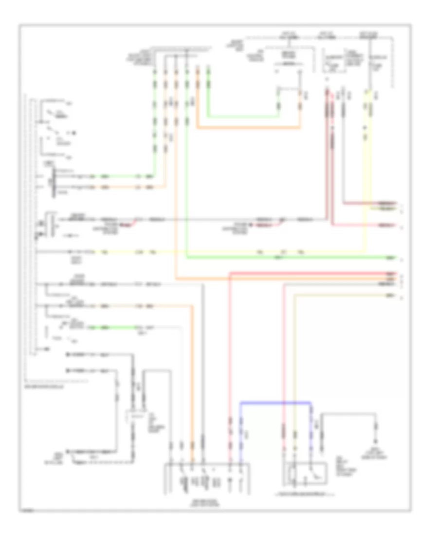
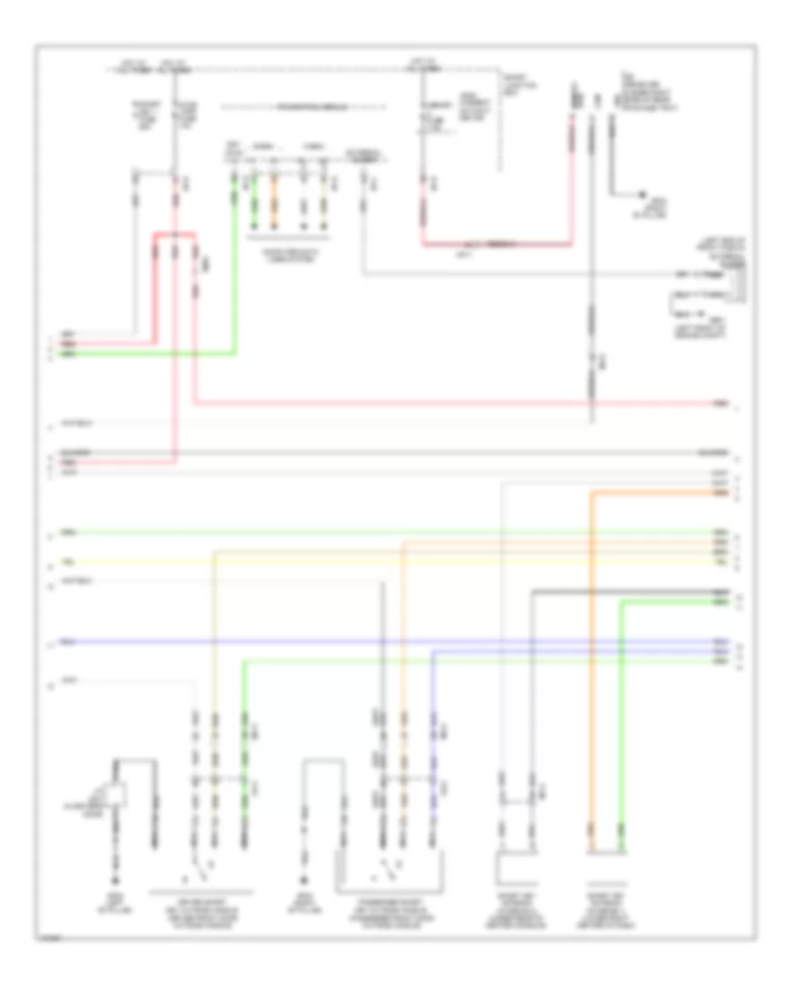
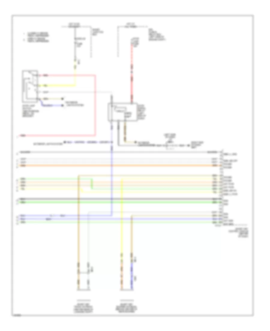
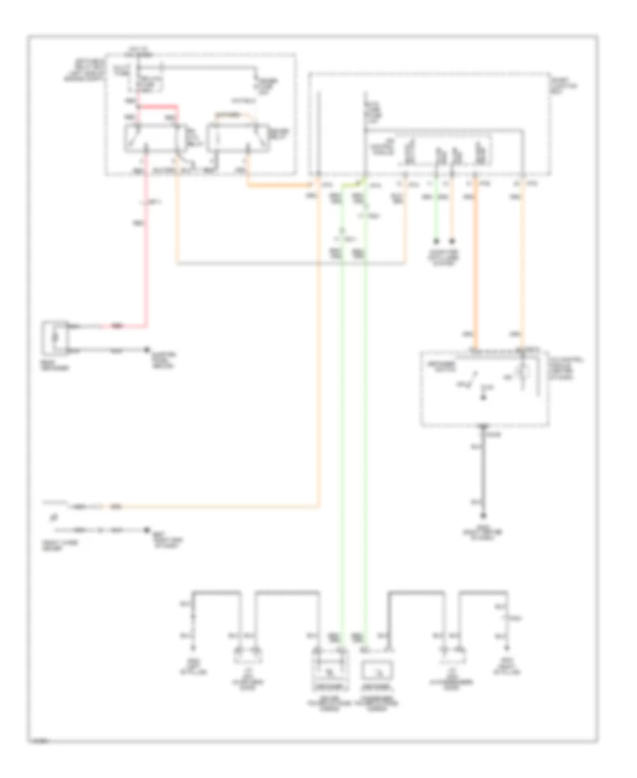
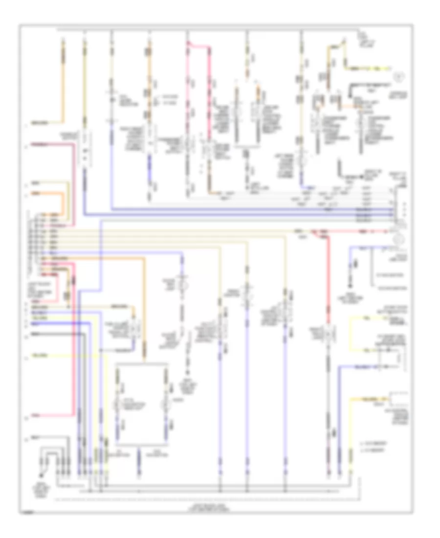
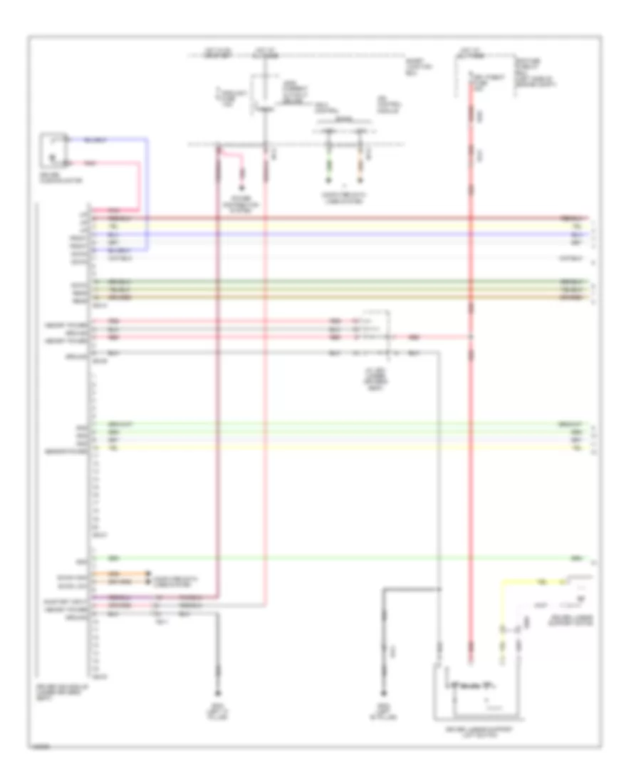
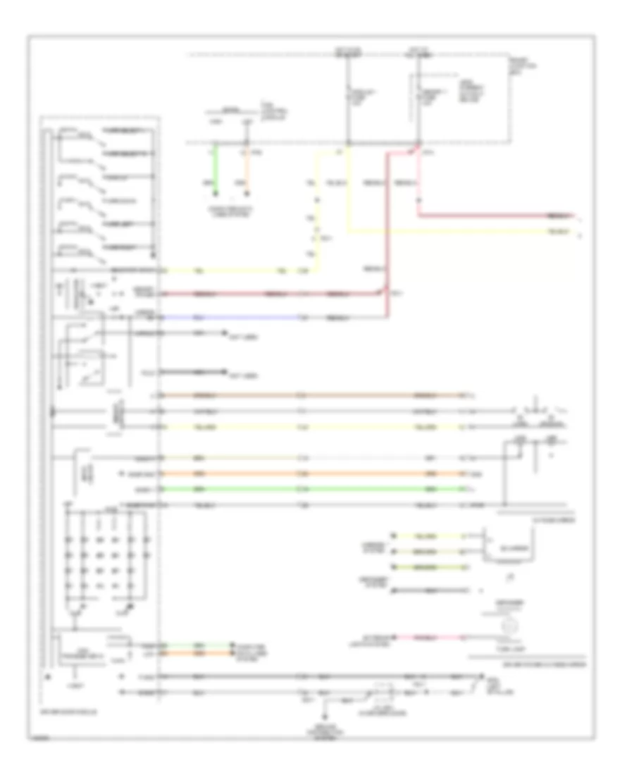
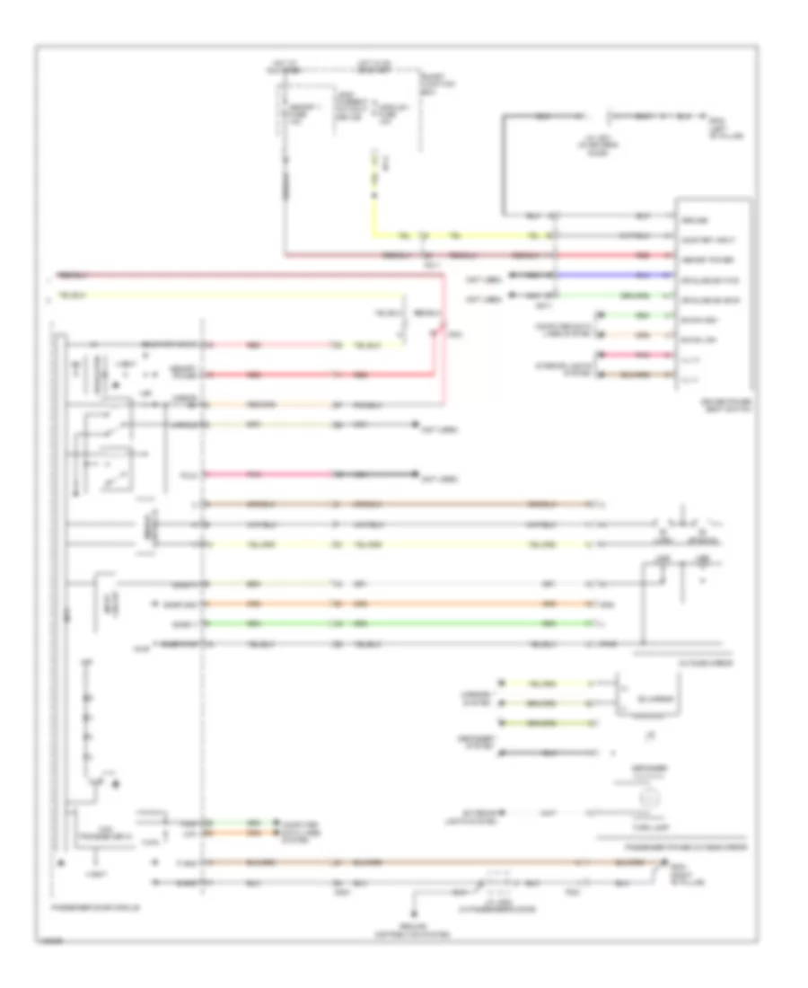
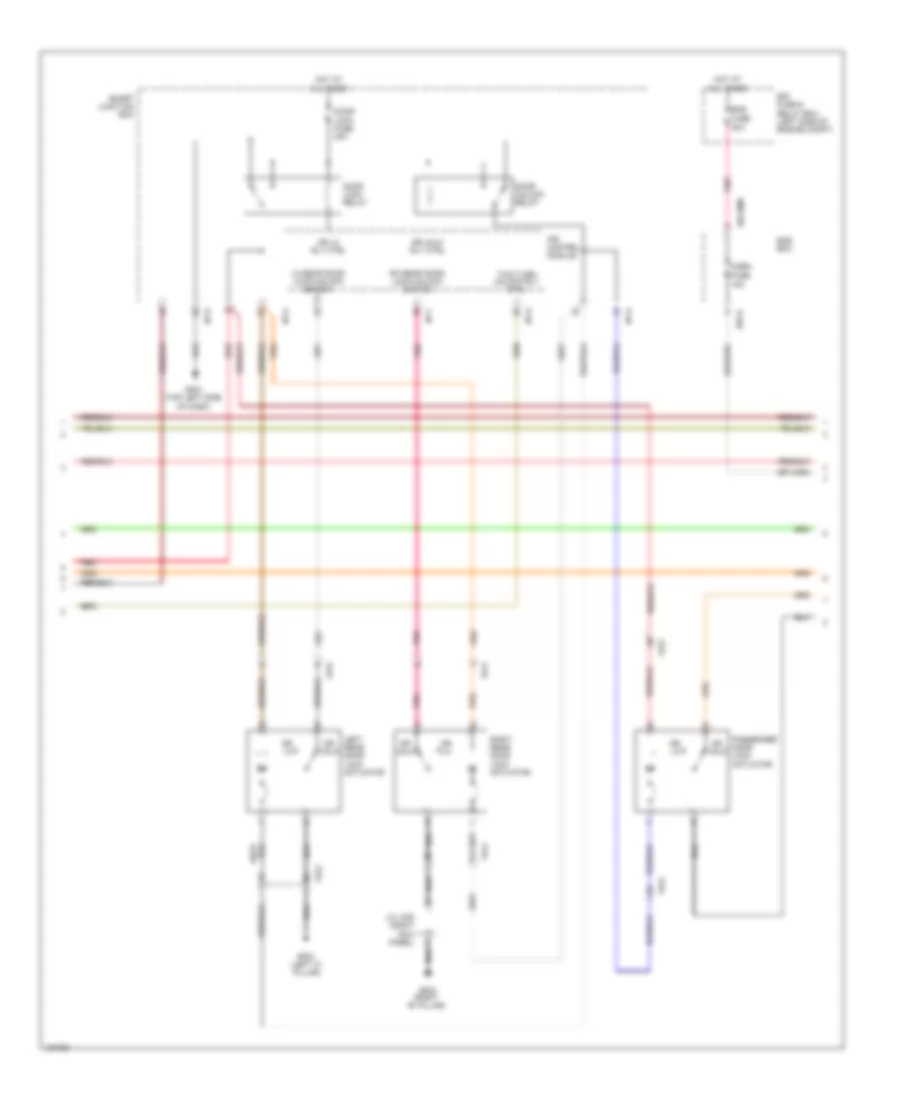
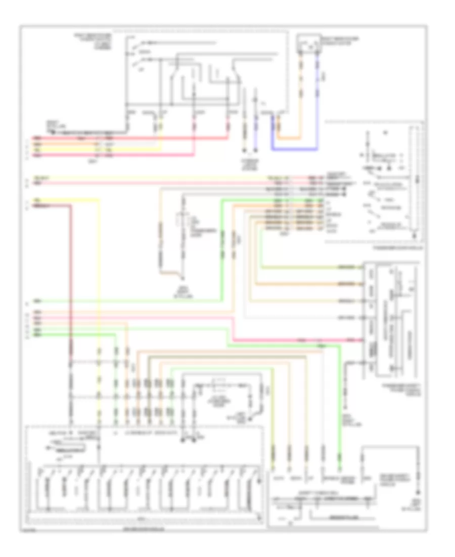
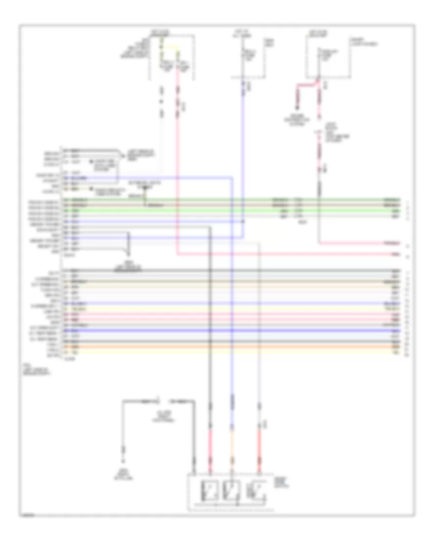
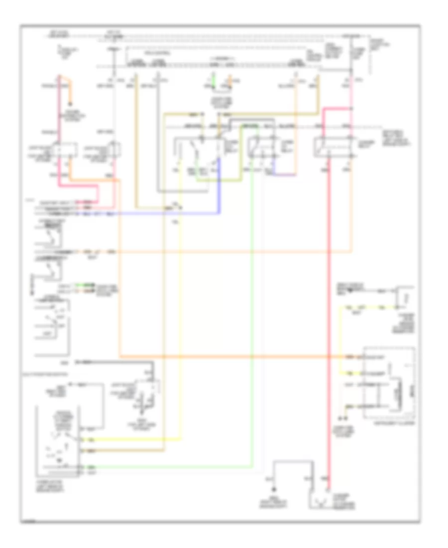
Automatic A/C Wiring Diagram (2 of 2) for Hyundai Azera 2014
List of elements for Automatic A/C Wiring Diagram (2 of 2) for Hyundai Azera 2014:
- (behind radiator) cooling fan motor
- (left front of engine compt) ge08
- (right front of engine compt) a/c pressure transducer
- Auto defogger actuator (upper right side of hvac unit)
- Auto defogger sensor
- Auto light & photo sensor (top center of dash)
- C-can hi
- C-can lo
- C/fan (hi) relay
- C/fan (high)
- C/fan (lo) relay
- C/fan (low)
- C/fan fuse 50a
- Clg-b
- Computer data lines system
- E/r fuse & relay box (left side of engine compt)
- E/r-b
- Ec21
- Ects gnd
- Ects sig
- Ecu 1 fuse 30a
- Ecu/ sensor 2 fuse 10a
- Elg-a
- Ems box
- Eng rly ctrl
- Engine control relay
- Engine controls system
- Engine coolant temperature sensor (rear of engine)
- Hot at all times
- Intake actuator (left side of hvac blower housing)
- Joint block jm02 (top center of dash)
- Left temperature actuator (left side of hvac unit)
- Mode actuator (left side of hvac unit)
- Mr11
- Nca
- Pcm (left side of engine compt)
- Photo sensor
- Pnk
- Red
- Right temperature actuator (right side of hvac unit)
- Rly ctrl
- Snsr gnd
- Snsr sig
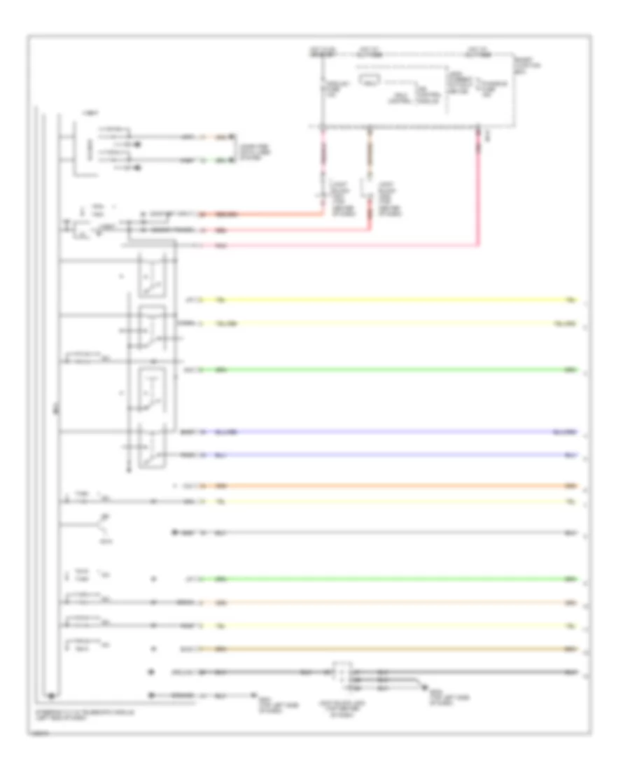
ANTI-LOCK BRAKES
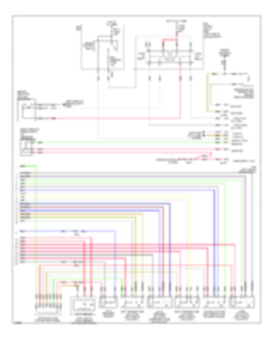
Anti-lock Brakes Wiring Diagram, with ESC (1 of 2) for Hyundai Azera 2014
List of elements for Anti-lock Brakes Wiring Diagram, with ESC (1 of 2) for Hyundai Azera 2014:
- (not used)
- Brake light switch
- Brake switch
- Brake test switch
- C-can high
- C-can low
- Can high
- Can low
- Clg-b
- Close w/ brake pedal depressed
- Computer data lines system
- E/r fuse & relay box (left side of engine compt)
- Ec21
- Ecu +
- Ef01
- Ef21
- Elg-a
- Em21
- Em31
- Esc 1 fuse 40a
- Esc 2 fuse 40a
- Esc control module (left rear of engine compt)
- Esc on/off switch
- Esc unit
- Exterior lights system
- Fl sig
- Fl vcc
- Foot parking brake sw
- Foot parking brake switch (above parking brake pedal, on bracket)
- Fr sig
- Fr vcc
- Ge10 (left side of dash)
- Gnd
- Ground
- Hot at all times
- Left front wheel sensor (left front wheel hub assembly)
- Left rear wheel sensor (left rear wheel hub assembly)
- M13-b
- Multi fuse
- Nca
- Open w/ brake pedal depressed
- Pcm (left side of engine compt)
- Pnk
- Power
- Red
- Right front wheel sensor (right front wheel hub assembly)
- Right rear wheel sensor (right rear wheel hub assembly)
- Rl sig
- Rl vcc
- Rr sig
- Rr vcc
- Rsm (relay stage monitoring)
- Smart key control module (center of dash)
- Stop lamp fuse 15a
- Stop lamp relay
- Stop lamp relay ctrl
- Stop lamp switch (above brake pedal, on bracket)
- Vbatt motor relay
- Vehicle speed sensor
- Wheel sens output (fr)
- Wheel speed
- Yaw rate sensor (front of center console)
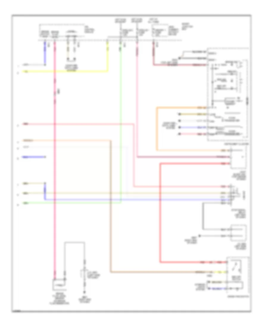
Anti-lock Brakes Wiring Diagram, with ESC (2 of 2) for Hyundai Azera 2014
List of elements for Anti-lock Brakes Wiring Diagram, with ESC (2 of 2) for Hyundai Azera 2014:
- Abs ind
- Brake fluid level
- Brake fluid level sensor (on brake fluid reservoir)
- Brake ind
- Brake switch (n.o)
- C-can
- C-can transceiver
- Circuit
- Computer data lines system
- Crash pad switch
- Em31
- Esc ind
- Esc off ind
- Esc off switch
- Ge07 (right end of dash)
- Gm04 (top left side of dash)
- High
- Hot at all times
- Hot in on or start
- I/p-c
- I/p-d
- I/p-e
- Instrument cluster
- Interior lights system
- Ips control module
- J/c je03 (left side of dash)
- Joint block jm01 (top center of dash)
- Leak current autocut device
- Low
- M-can transceiver
- Memory 1 fuse 10a
- Micom
- Mm02
- Module 1 fuse 10a
- Module 2 fuse 7.5a
- Pnk
- Red
- Sgnd 1
- Sgnd 2
- Smart junction box
- Stop signal relay (left end of dash)
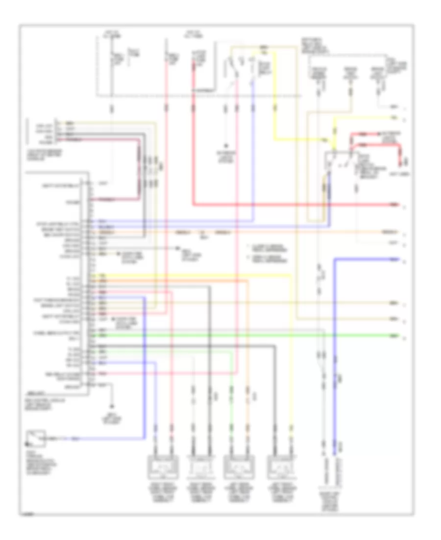
Anti-lock Brakes Wiring Diagram, without ESC (1 of 2) for Hyundai Azera 2014
List of elements for Anti-lock Brakes Wiring Diagram, without ESC (1 of 2) for Hyundai Azera 2014:
- (not used)
- Abs control module (left rear of engine compt)
- Abs unit
- Brake light switch
- Brake switch
- Brake test switch
- C-can high
- C-can low
- Clg-b
- Close w/ brake
- Computer data lines system
- E/r fuse & relay box (left side of engine compt)
- Ec21
- Ecu +
- Ef01
- Ef21
- Elg-a
- Em31
- Esc 1 fuse 40a
- Esc 2 fuse 40a
- Fl sig
- Fl vcc
- Fr sig
- Fr vcc
- Ge10 (left side of dash)
- Ground
- Hot at all times
- Left front wheel sensor (left front wheel hub assembly)
- Left rear wheel sensor (left rear wheel hub assembly)
- M13-b
- Multi fuse
- Nca
- Open w/ brake pedal depressed
- Pcm (left side of engine compt)
- Pedal depressed
- Pnk
- Red
- Right front wheel sensor (right front wheel hub assembly)
- Right rear wheel sensor (right rear wheel hub assembly)
- Rl sig
- Rl vcc
- Rr sig
- Rr vcc
- Smart key control module (center of dash)
- Stop lamp fuse 15a
- Stop lamp switch (above brake pedal, on bracket)
- Vbatt
- Vbatt motor relay
- Veh spd snsr
- Wheel sens output (fr)
- Wheel speed
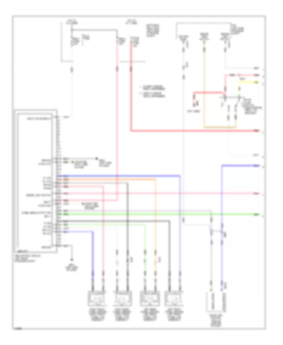
Anti-lock Brakes Wiring Diagram, without ESC (2 of 2) for Hyundai Azera 2014
List of elements for Anti-lock Brakes Wiring Diagram, without ESC (2 of 2) for Hyundai Azera 2014:
- Abs ind
- Brake fluid level
- Brake fluid level sensor (on brake fluid reservoir)
- Brake ind
- Brake switch (n.o)
- C-can
- C-can transceiver
- Circuit
- Computer data lines system
- Em31
- Exterior lights system
- Foot parking brake switch
- Foot parking brake switch (above parking brake pedal, on bracket)
- Ge07 (right end of dash)
- Gm04 (top left side of dash)
- High
- Hot at all times
- Hot in on or start
- I/p-c
- I/p-d
- I/p-e
- Instrument cluster
- Ips control module
- J/c je03 (left side of dash)
- Joint block jm01 (top center of dash)
- Leak current autocut device
- Low
- M-can transceiver
- Memory 1 fuse 10a
- Micom
- Module 1 fuse 10a
- Module 2 fuse 7.5a
- Nca
- Pnk
- Red
- Sgnd 1
- Sgnd 2
- Smart junction box
- Stop lamp fuse 10a
- Stop signal relay (left end of dash)
ANTI-THEFT
Forced Entry Wiring Diagram (1 of 3) for Hyundai Azera 2014
List of elements for Forced Entry Wiring Diagram (1 of 3) for Hyundai Azera 2014:
- (top left side of dash)
- +5v
- +vbat
- B-can
- Ctl lock
- Ctl unlock
- Dd11
- Door
- Door unlock switch
- Door)
- Driver door lock actuator
- Driver door module
- Fd11
- Gf02 (left "b" pillar)
- Gm01
- Hot at all times
- Hot in on or start
- I/p-a
- I/p-d
- I/p-e
- Icm relay box (right end of dash)
- Ips control module
- J/c jd01 (in driver's
- Joint block jm02 (top center of dash)
- Key lock
- Key lock switch
- Key unlock switch
- Leak current autocut device
- Lock door
- Mcu
- Memory fuse 10a
- Memory power
- Mf11
- Mf21
- Module fuse 10a
- On/st input
- P gnd
- Power distribution system
- Red
- Regulator
- S gnd
- Smart junction box
- Transceiver ic can
- Two turn unlock relay
- Unlock
- Unlock key
Forced Entry Wiring Diagram (2 of 3) for Hyundai Azera 2014
List of elements for Forced Entry Wiring Diagram (2 of 3) for Hyundai Azera 2014:
- (top left side of dash)
- Door lock fuse 20a
- Door lock relay
- Door unlock relay
- Dr lk
- Dr lk rly ctrl
- Dr unlk
- Dr unlk rly ctrl
- E/r fuse & relay box (left side of engine compt)
- E/r-a
- E/r-ems
- Ems
- Ems box
- Fd21
- Fd31
- Fd41
- Fuse 40a
- Gf03 (right "b" pillar)
- Gf04 (left "c" pillar)
- Gm01
- Horn fuse 15a
- Hot at all times
- I/p-a
- I/p-d
- I/p-e
- I/p-f
- Ips control module
- J/c jf05 (right kick panel)
- Left rear door lock actuator
- Lh rear door lock/unlock switch
- Passenger door lock actuator
- Pnk
- Red
- Rh rear door lock/unlock switch
- Right rear door lock actuator
- Smart junction box
- Two turn unlock rly ctrl
Forced Entry Wiring Diagram (3 of 3) for Hyundai Azera 2014
List of elements for Forced Entry Wiring Diagram (3 of 3) for Hyundai Azera 2014:
- (top center of dash) auto light & photo sensor
- +5v
- +vbat
- Burglar alarm horn (right rear of engine compt)
- Burglar horn relay
- Burglar horn rly ctrl
- Ctl
- Dd21
- Door
- Em21
- Em31
- Engine compt)
- Fd21
- Ge02 (right side of engine compt)
- Ge07 (right end of dash)
- Gf03 (right "b" pillar)
- Hood sw
- Hood switch (right side of
- I/p-c
- I/p-e
- Icm relay box (right end of dash)
- Ips control module
- J/c jd02 (in passenger's door)
- J/c je03 (left side of dash)
- Lock
- Mcu
- Memory power
- Nca
- On/st input
- P gnd
- Passenger door module
- Power distribution system
- Red
- Regulator
- S gnd
- Security ind
- Smart junction box
- Transceiver ic can
- Unlock
- Unlock switch
Immobilizer Wiring Diagram, with Smart Key System (1 of 3) for Hyundai Azera 2014
List of elements for Immobilizer Wiring Diagram, with Smart Key System (1 of 3) for Hyundai Azera 2014:
- "p" position switch
- (right end of dash)
- (upper right center of dash) gm07
- Acc
- Acc rly
- Acc/on input
- Anti-lock brakes system
- Audio fuse 10a
- B-can hi
- B-can lo
- Brake sw
- C-can hi
- C-can lo
- Com
- Computer data lines system
- Driver dr lk/ unlk sw
- E/r fuse & relay box (left side of engine compt)
- Elg-a
- Em31
- Ems com
- Engine controls system
- Engine rpm
- Ge07
- Gf03 (right "b" pillar)
- Gm04 (top left
- Gnd
- Hot at all times
- I/p-d
- Ig1 rly
- Ig2 rly
- Ign 1 fuse 40a
- Ign 2 fuse 40a
- Ill
- Immo ant
- Immo ant gnd
- Immo ant pwr
- Immo fuse 7.5a
- Interior lights system
- J/b jm03 (top center of dash)
- J/c je03 (left side of dash)
- J/c jf05 (right kick panel)
- K-line
- M13-a
- M13-b
- Memory power
- Memory pwr
- Mf21
- Module fuse 7.5a
- Multi fuse
- Off
- On input
- On/start input
- P position
- Pass dr lk/ unlk sw
- Pcm (left side of engine compt)
- Pdm 1 (acc) relay
- Pdm 2 (ig1) relay
- Pdm 3 (ig2) relay
- Pnk
- Power distribution system
- Pwr
- Red
- Rheostat
- Sbb pwr
- Side of dash)
- Smart junction box
- Smart key control module (center of dash)
- Sport mode switch
- Ssb gnd
- Ssb led acc
- Ssb sw 1
- Ssb sw 2
- Ssb sw1
- Ssb sw2
- St feedback sig
- St rly
- Start/stop button switch
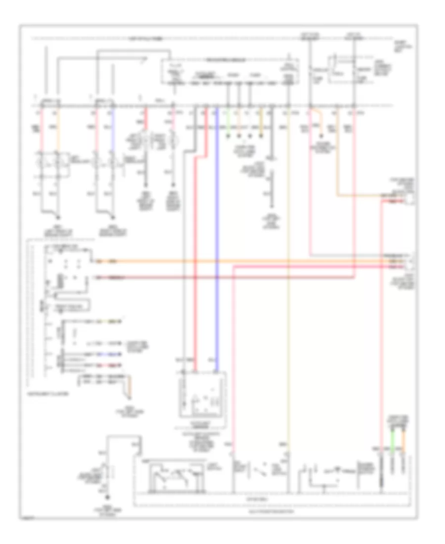
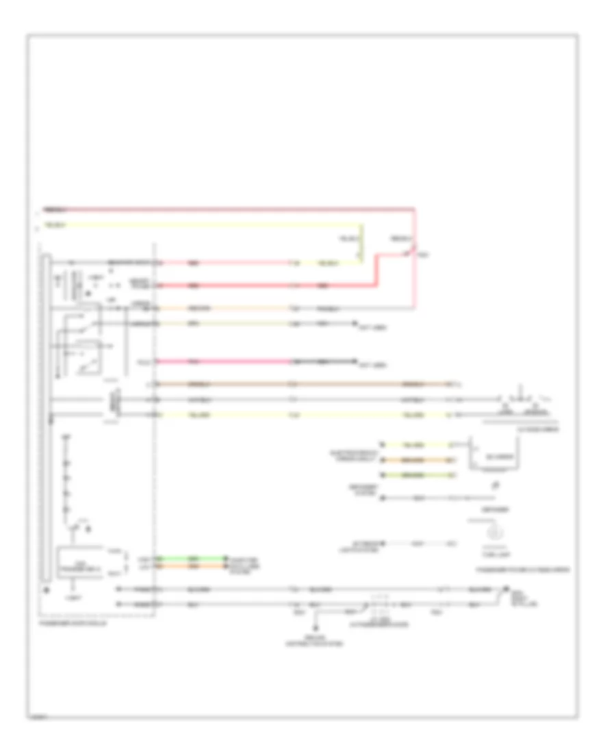
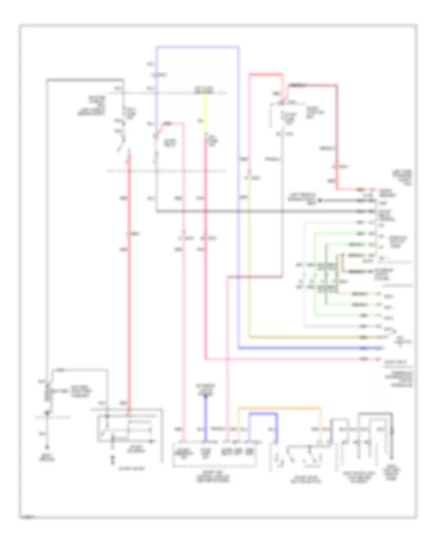
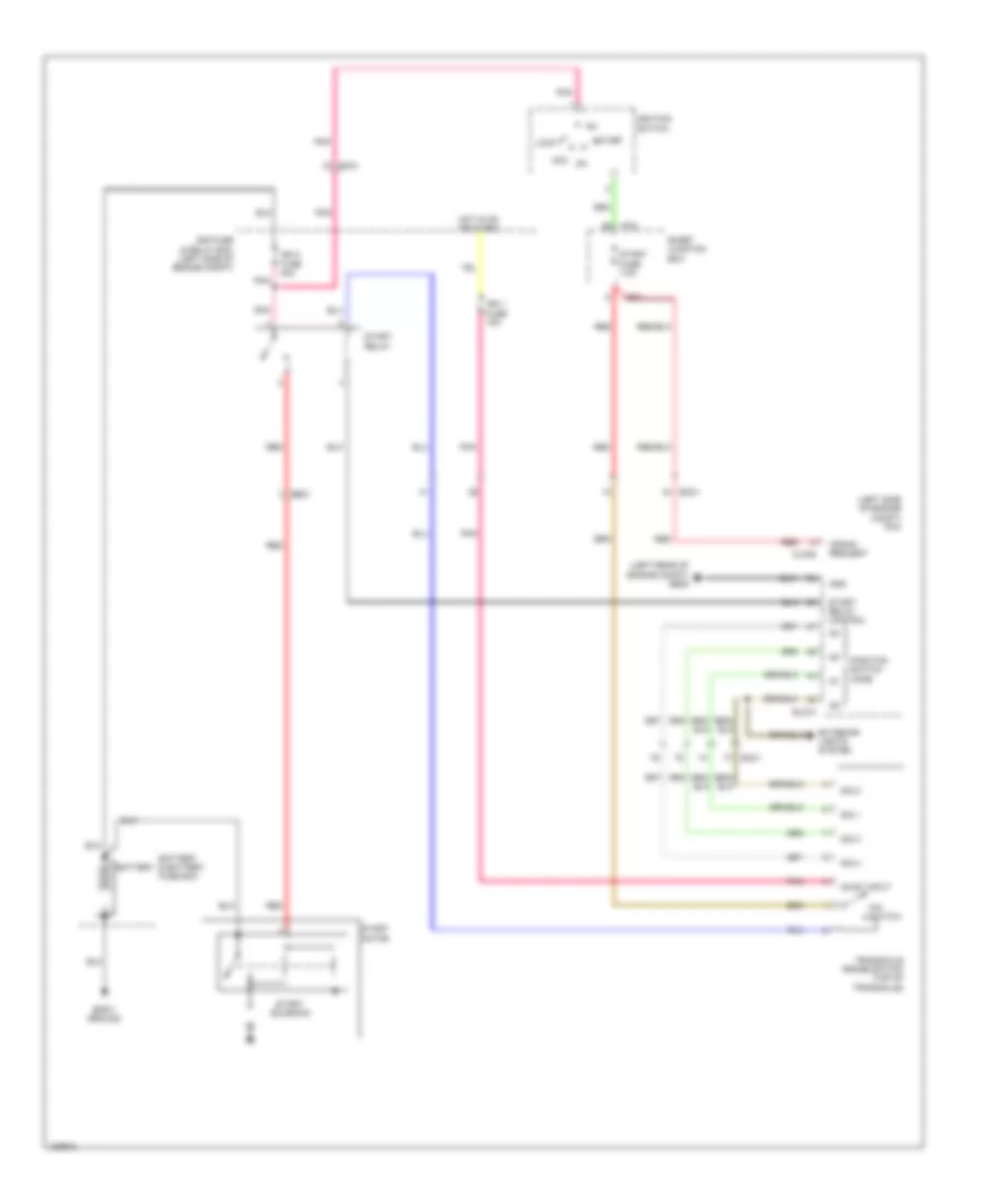
- Starting/charging system
- Wheel speed
Immobilizer Wiring Diagram, with Smart Key System (2 of 3) for Hyundai Azera 2014
List of elements for Immobilizer Wiring Diagram, with Smart Key System (2 of 3) for Hyundai Azera 2014:
- (driver front door outside handle)
- (left end of front fascia)
- (left front of engine compt)
- (passenger front door outside handle)
- (under right side of rear package tray)
- B-can
- C-can
- Com
- Computer data lines system
- Driver smart key outside handle
- Em31
- External buzzer
- Fd11
- Fd21
- Ge01
- Gf02 (left "b" pillar)
- Gf03 (right "b" pillar)
- Gnd
- Hot at all times
- I/p-c
- I/p-d
- I/p-e
- Ips control module
- J/c jd01 (in driver's door)
- Key hole ill
- Leak current autocut device
- Memory fuse 7.5a
- Memory pwr
- Mf11
- Mf21
- Nca
- Passenger smart key outside handle
- Red
- Rf receiver
- Smart junction box
- Smart key 1 fuse 25a
- Smart key antenna (interior 1) (lower right center of dash)
- Smart key antenna (interior 2) (under rear of center console)
- Stop lamp fuse 10a
Immobilizer Wiring Diagram, with Smart Key System (3 of 3) for Hyundai Azera 2014
List of elements for Immobilizer Wiring Diagram, with Smart Key System (3 of 3) for Hyundai Azera 2014:
- (above brake pedal, on bracket)
- (left side of dash)
- (or pnk)
- (or red)
- (right end of dash) ge07
- Ant gnd
- Ant pwr
- Circuit
- Closed w/ brake pedal depressed
- E/r fuse & relay box (left side of engine compt)
- Em31
- Exterior lights system
- Fr01
- Gnd
- Hot at all times
- Hot in on or start
- I/p-c
- J/c je03
- M13-c
- Mf11
- Mf21
- Module fuse 10a
- Open w/ brake pedal depressed
- Power
- Red
- Sbb ill gnd
- Smart junction box
- Smart key bumper antenna (behind center of rear bumper)
- Smart key control module (center of dash)
- Smart key trunk antenna (center rear of luggage compt)
- Ssb ill pwr
- Ssb led off
- Ssb led on
- Stop lamp fuse 15a
- Stop lamp switch
- Stop signal relay (left end of dash)
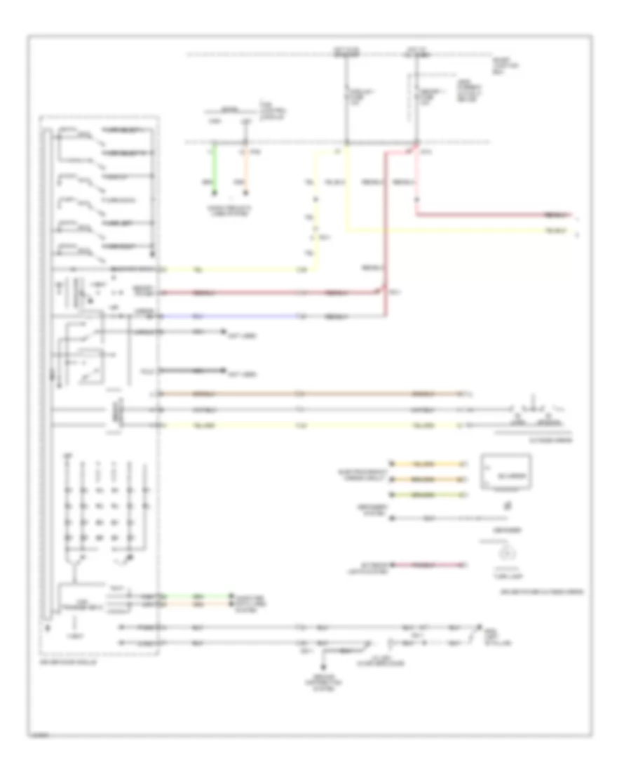
Immobilizer Wiring Diagram, without Smart Key System for Hyundai Azera 2014
List of elements for Immobilizer Wiring Diagram, without Smart Key System for Hyundai Azera 2014:
- Antenna coil
- Coil(+)
- Coil(-)
- Computer data lines system
- Elg-a
- Em31
- Ems
- Gm04 (top left
- Gnd
- Hot at all times
- Hot in on or start
- I/p-d
- Ignition key illumination & door warning switch (on ignition switch assembly)
- Immo fuse 7.5a
- Immo ind
- Immobilizer module (top left side of dash)
- Ind
- Input sig interface
- Instrument cluster
- Joint block jm03 (top center of dash)
- K-line
- K-line sig interface
- Leak current autocut device
- Memory fuse 10a
- Memory pwr
- Micro controller
- Nca
- On/st input
- Pcm (left side of engine compt)
- Pnk
- Red
- Serial sig interface
- Side of dash)
- Smart junction box
- Stop lamp fuse 10a
- Transponder
- Transponder reader ic
BODY CONTROL MODULES
Body Control Modules Wiring Diagram (1 of 3) for Hyundai Azera 2014
List of elements for Body Control Modules Wiring Diagram (1 of 3) for Hyundai Azera 2014:
- (or red)
- Acc
- Acc/on input
- Arisu-lt1 ctrl
- Arisu-lt2
- Arisu-lt2 control
- Arisu-lti
- B-can
- C-can
- C-can transceiver
- Computer data lines system
- Ctrl
- Door locks system
- Driver
- E/r fuse & relay box
- Em31
- Exterior lights system
- Fd11
- Fd21
- Headlights system
- High
- Hot at all times
- I/p-a
- I/p-c
- I/p-d
- I/p-e
- I/p-f
- Ignition switch
- Instrument cluster
- Interior lights system
- Ips 1
- Ips 1 ctrl
- Ips 2
- Ips 3
- Ips 3 control
- Ips 4
- Ips 4 control
- Ips control module
- Joint block jm01 (top center of dash)
- Lock
- Low
- M-can
- Micom
- Module 1 fuse 10a
- On/start input
- Passenger
- Pdm 1 (acc) relay
- Pdm 2 (ig 1) relay
- Pnk
- Power windows
- Red
- Restraints system
- Rly ctrl
- Seat belt buckle switch
- Seat belt ind
- Smart junction box
- Start
- System
- Two turn
- Unlock
- W/ smart key
- W/o smart key
Body Control Modules Wiring Diagram (2 of 3) for Hyundai Azera 2014
List of elements for Body Control Modules Wiring Diagram (2 of 3) for Hyundai Azera 2014:
- (headlamp `on' signal)
- Air conditioning system
- Anti-theft
- Anti-theft system
- Auto hlld
- Auto light sensor
- Box
- Brake
- Burglar horn relay control
- Buz
- Crash
- Curtain
- Defog
- Defogger system
- Door switch
- Down
- Driver
- Drv
- Exterior
- Exterior lights system
- External
- Foot
- Gf04 (left "c" pillar)
- Ground
- Handle
- Haz sw in
- Headlamp low signal
- Headlights system
- High
- Hood sw
- I/p-c
- I/p-e
- I/p-f
- Ill
- Ind
- Input
- Inter lk
- Interior lights system
- Ips control module
- Junction
- Key
- Key hole
- Lamp
- Lh rear pwr
- Lights
- Lin sensor
- Low
- Main sw
- Mood lamp
- Navigation system
- Output
- Pas sw sig
- Passenger
- Pnk
- Power
- Power window system
- Power windows
- Pwr
- Rain sensor
- Rear
- Rear defog relay ctrl
- Rear lh
- Rear pwr
- Rear rh
- Red
- Restraints
- Rh rear pwr window sw
- Room lamp
- S/b sw
- Sbr ind
- Security
- Shift interlock
- Shift lk
- Signal
- Smart
- Smart junction box
- Sol
- Stop
- Sw (n.o)
- Sw in
- Switch
- System
- Trunk
- Trunk lid
- Trunk room lamp
- Trunk, tailgate, fuel doors system
- Window
- Window sw
- Wip signal
- Wiper/washer
Body Control Modules Wiring Diagram (3 of 3) for Hyundai Azera 2014
List of elements for Body Control Modules Wiring Diagram (3 of 3) for Hyundai Azera 2014:
- Acc
- Anti-theft & door locks systems
- Brake fluid level
- Distribution
- Door lock relay
- Door lock relay ctrl
- Door unlock relay
- Door unlock relay ctrl
- Dr lock fuse 20a
- Dr warn sw
- E/r fuse & relay box
- Em31
- Foot parking brake sw
- Gm04 (top left side of dash)
- Gnd
- Hot at all times
- I/p-a
- I/p-b
- I/p-c
- I/p-d
- I/p-e
- I/p-f
- Ignition key illumination & door warning switch (w/o smart key) (on ignition switch assembly)
- Ignition switch
- Ill
- Instrument cluster system
- Ip b+1 fuse 40a
- Ips 5
- Ips 5 ctrl
- Ips control module
- Joint block jm02 (top center of dash)
- Joint block jm03 (top center of dash)
- Key
- Key in
- Leak current autocut
- Leak current autocut device
- Leak current autocut relay
- Leak current autocut switch
- Lock
- Mem pwr
- Nca
- Off
- On in
- Pdm 3 (ig 2) relay
- Pnk
- Power
- Rear dr lk/
- Red
- Relay ctrl
- Smart
- Smart junction box
- Start
- Sw ctrl
- System
- Unlk sig
- W/o
COMPUTER DATA LINES
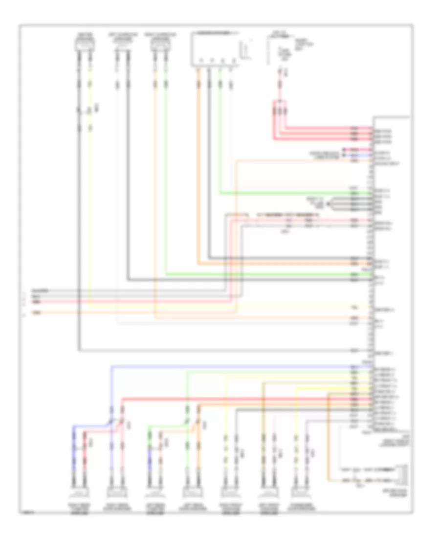
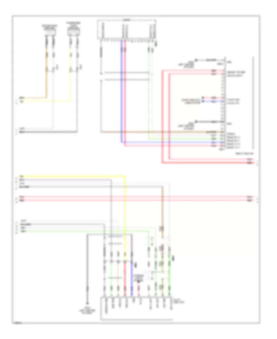
Computer Data Lines Wiring Diagram (1 of 2) for Hyundai Azera 2014
List of elements for Computer Data Lines Wiring Diagram (1 of 2) for Hyundai Azera 2014:
- (center of dash) smart key control module
- (not used)
- (right rear wheelwell) auto headlamp leveling device module
- (top left side of dash) (w/ immo) immobilizer module
- 4p out
- A/c control module (center of dash)
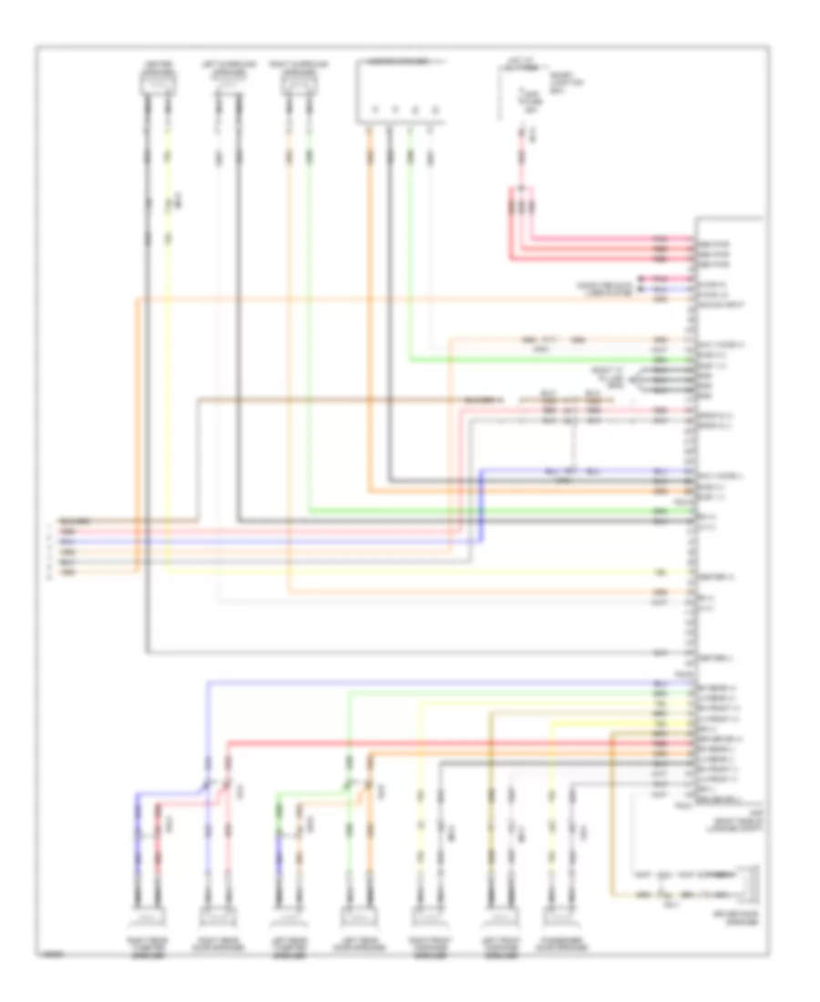
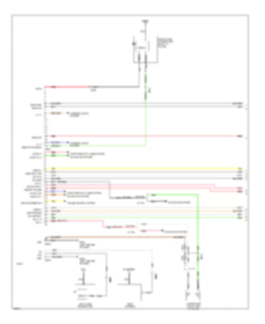
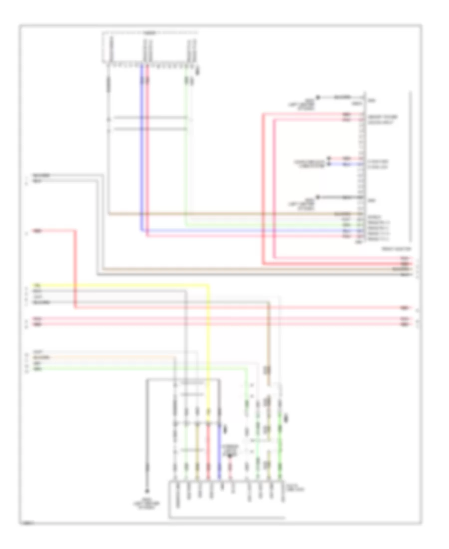
- A/v & navigation headunit
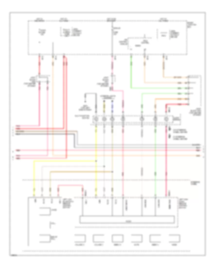
- Amp (right side of luggage compt)
- Audio
- Auto headlamp leveling device module (right rear wheelwell)
- B-can hi
- B-can lo
- C-can hi
- C-can lo
- C-can transceiver
- Data link connector (below left end of dash)
- Dd11
- Dd21
- Driver door module
- Driver ims module (w/ ims) (under driver's seat)
- Driver power seat switch (w/ ims)
- Em31
- F02-a
- Fd11
- Fd21
- Front monitor (audio)
- Fs11
- Gm01 (top left side of dash) gm04 (top left side of dash)
- Gm04 (top left side of dash)
- Gnd
- Hot at all times
- I/p-d
- I/p-e
- Instrument cluster
- Ips control module
- Joint block jm01 (top center of dash)
- Joint block jm02 (top center of dash)
- Joint block jm03 (top center of dash)
- K-line
- Leak current autocut device
- M-can
- M-can hi
- M-can lo
- M01-r
- M03-a
- M09-b
- M10
- M13-a
- M13-b
- M14-b
- M26
- Mdps unit (on steering column)
- Memory 1 fuse 10a
- Mf11
- Mf21
- Micom
- Mr11
- Multi-function switch
- Multi-function switch (remote control)
- Panorama sunroof
- Passenger door module
- Pnk
- Power distribution system
- Red
- S04-d
- Smart junction box
- Srs control module (front of center console)
- Steering tilt & telescopic module (left end of dash)
- Telematics unit
- Transceiver
- W/ navigation
- W/o navigation
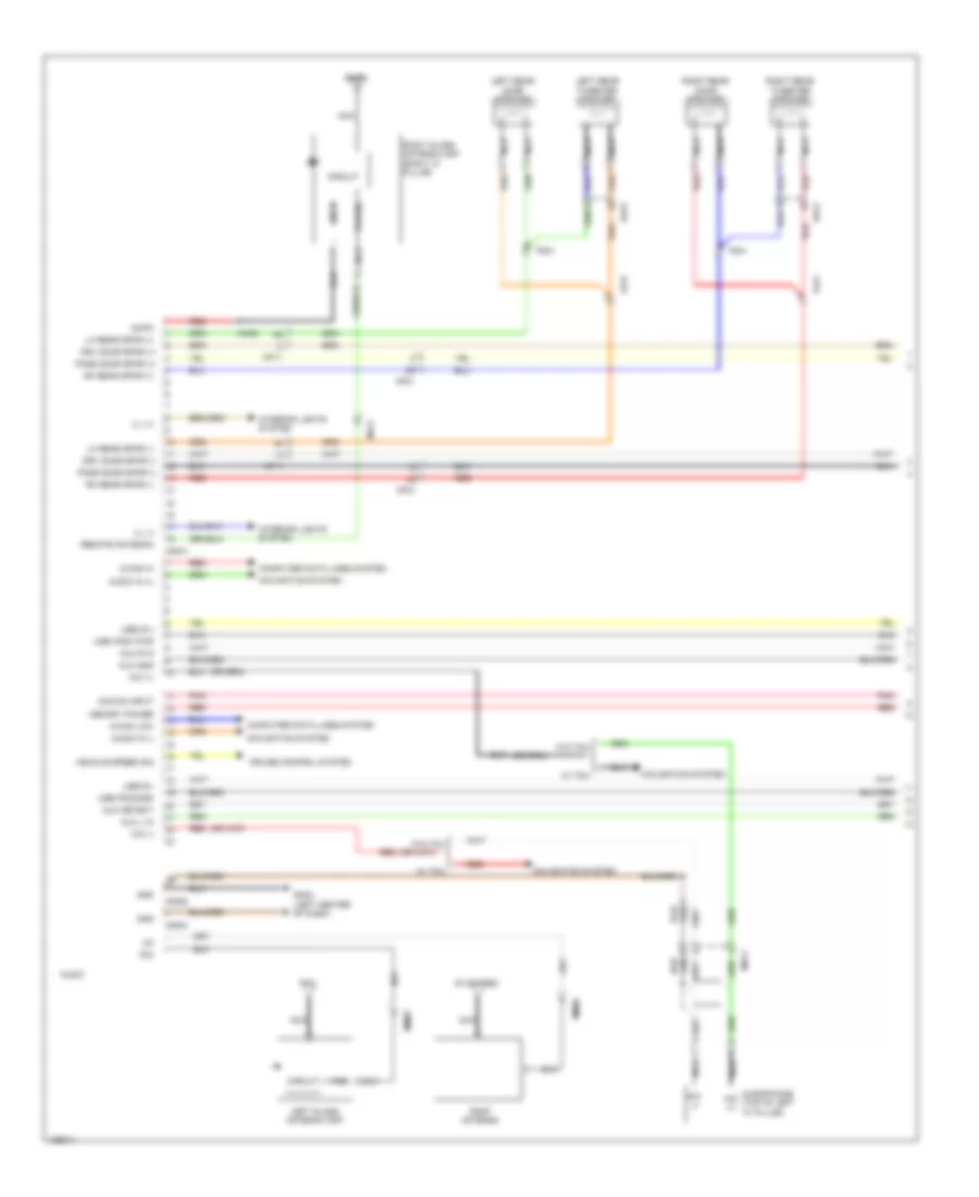
Computer Data Lines Wiring Diagram (2 of 2) for Hyundai Azera 2014
List of elements for Computer Data Lines Wiring Diagram (2 of 2) for Hyundai Azera 2014:
- Abs
- Abs control module (left rear of engine compt)
- C-can hi
- C-can lo
- Ccp can hi
- Ccp can lo
- Diagnosis fuse 20a
- E/r fuse & relay box
- Ec21
- Ecu 5 fuse 10a
- Ef01
- Elg-a
- Em31
- Esc
- Esc module (left rear of engine compt)
- Fr01
- Ge07 (right end of dash)
- Hot at all times
- Hot in on or start
- Idb (injector driver box) (left rear of engine compt)
- J/c je01 (right end of dash)
- J/c je04 (left end of dash)
- J/c jf03 (under center console)
- J/c jf05 (right kick panel)
- J/c jr01 (center front of roof)
- Lin
- Lin line
- Mf11
- Mf21
- Mr11
- Multipurpose check connector (right rear of engine compt)
- Passenger occupant detection sensor (under passenger's seat)
- Pcm (left side of engine compt)
- Red
- Tire pressure monitoring module (behind center of rear bumper)
- W/ immo
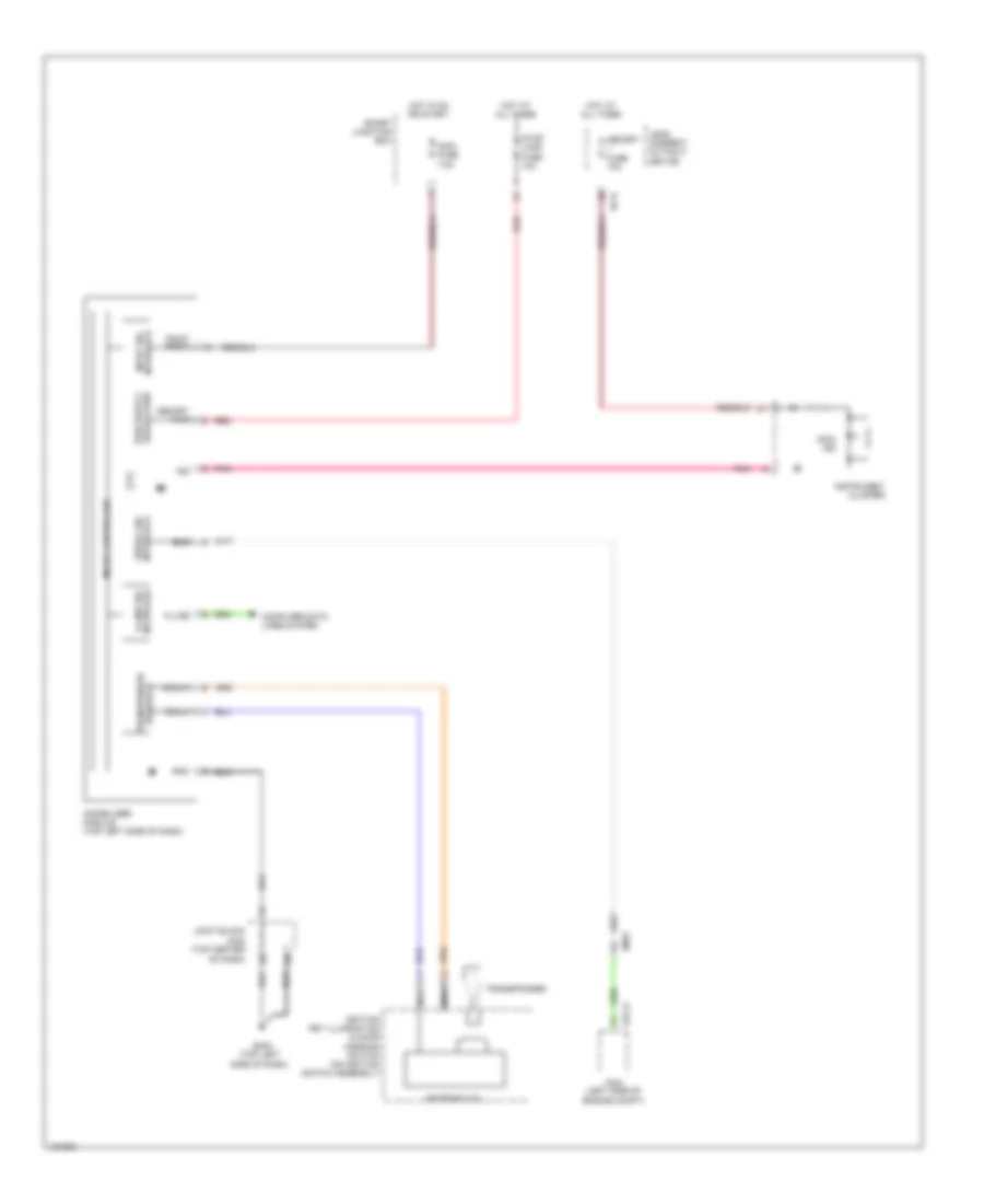
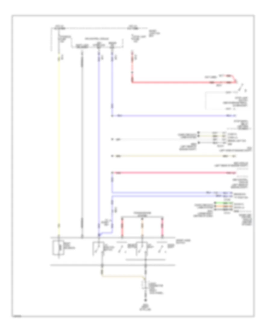
COOLING FAN
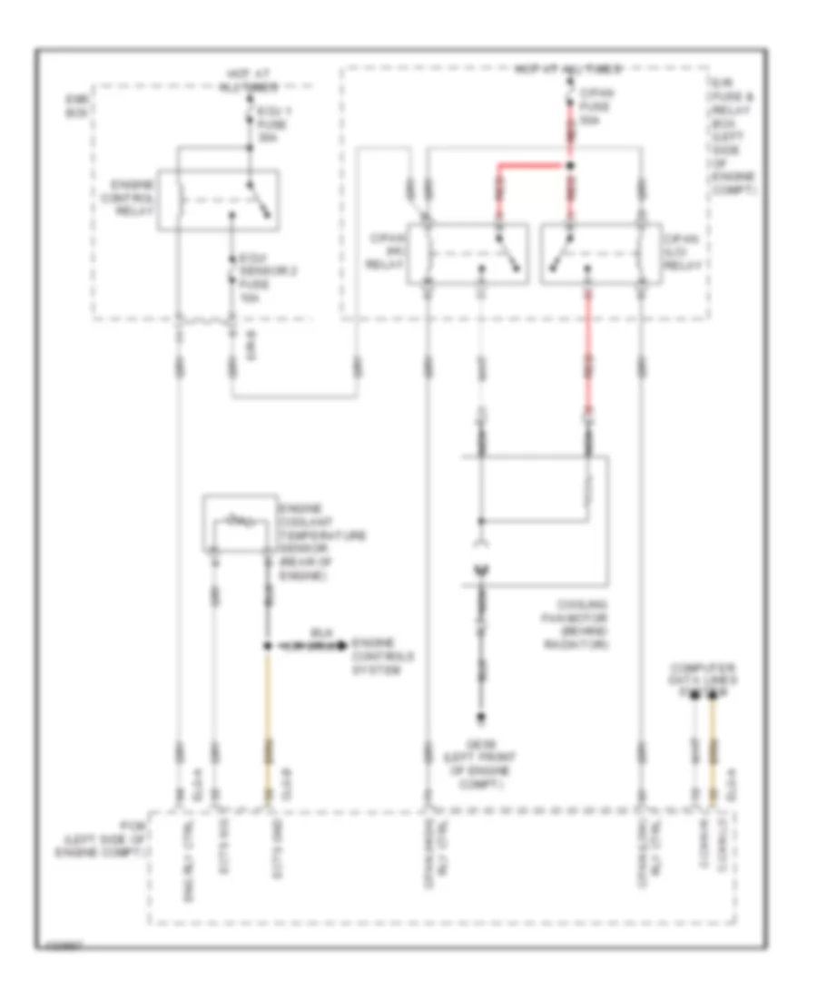
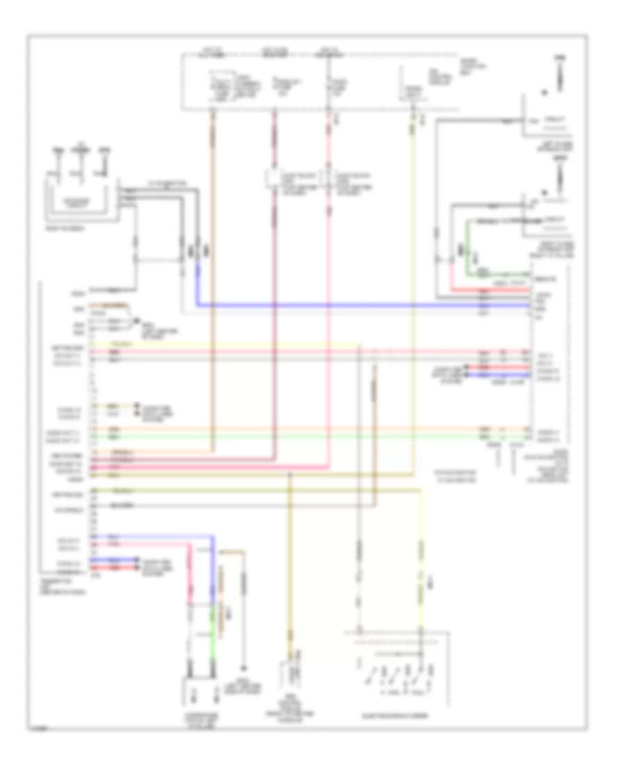
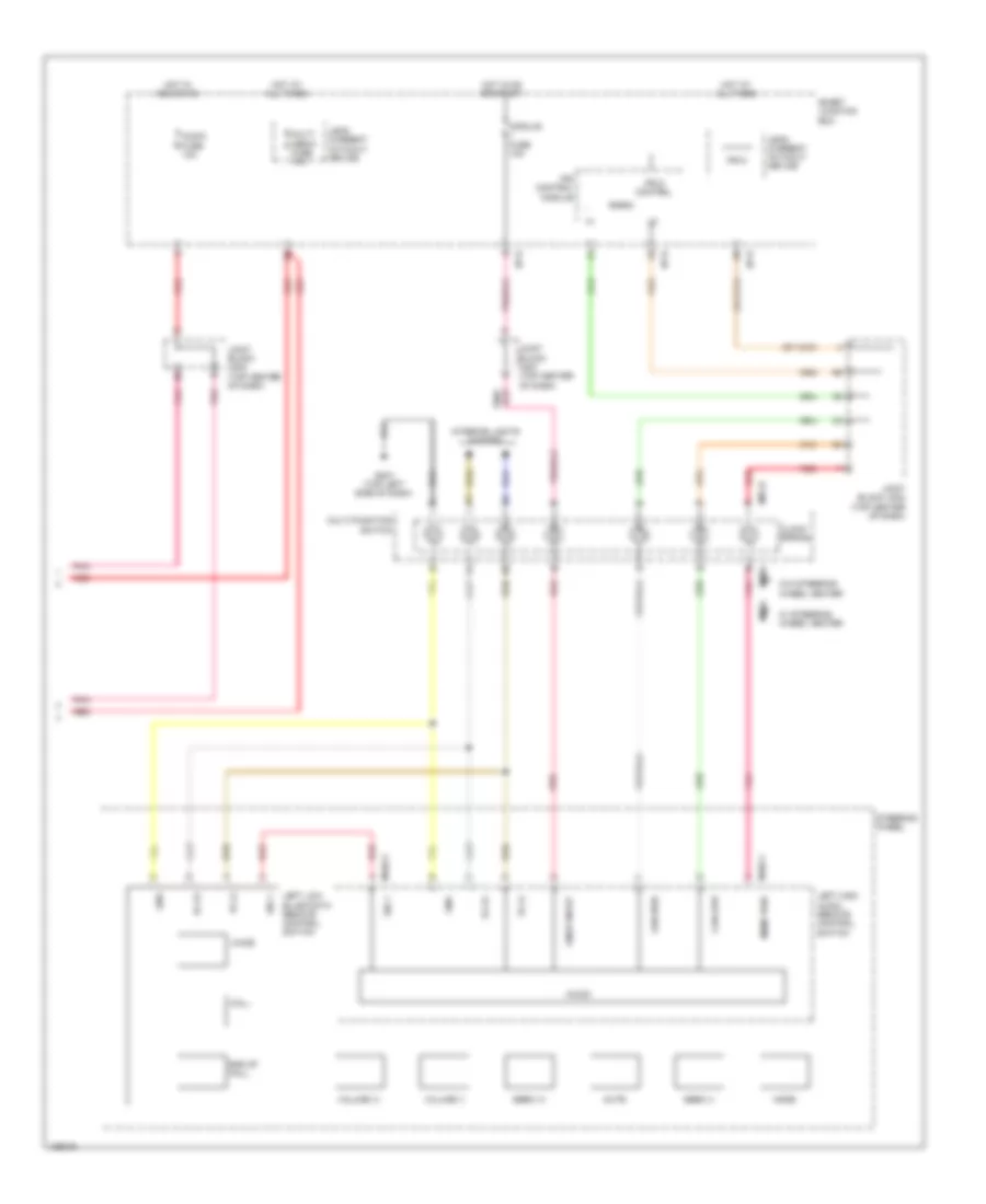
Cooling Fan Wiring Diagram for Hyundai Azera 2014
List of elements for Cooling Fan Wiring Diagram for Hyundai Azera 2014:
- C-can hi
- C-can lo
- C/fan (hi) relay
- C/fan (lo) relay
- C/fan fuse 50a
- Clg-b
- Computer data lines system
- Cooling fan motor (behind radiator)
- E/r fuse & relay box (left side of engine compt)
- E/r-b
- Ects gnd
- Ects sig
- Ecu 1 fuse 30a
- Ecu/ sensor 2 fuse 10a
- Elg-a
- Ems box
- Eng rly ctrl
- Engine control relay
- Engine controls system
- Engine coolant temperature sensor (rear of engine)
- Ge08 (left front of engine compt)
- Hot at all times
- Nca
- Pcm (left side of engine compt)
- Red
- Rly ctrl c/fan (high)
- Rly ctrl c/fan (low)
CRUISE CONTROL
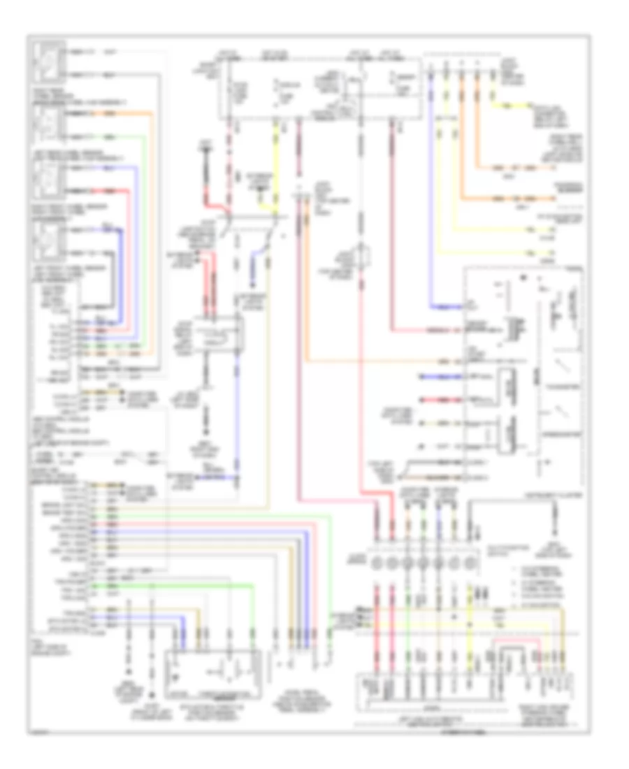
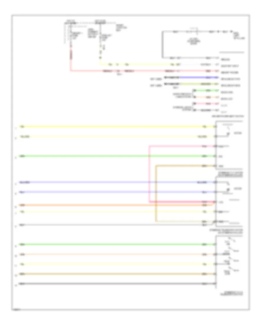
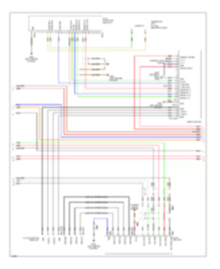
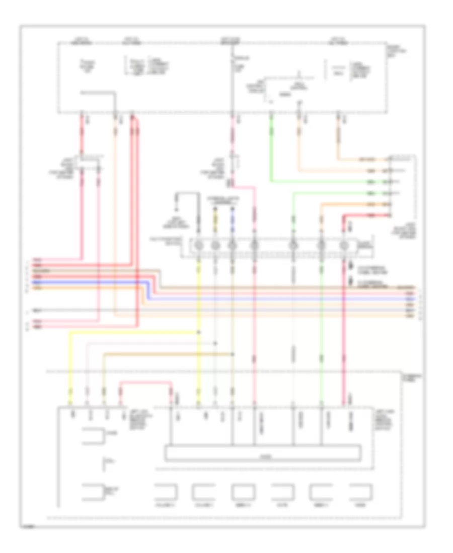
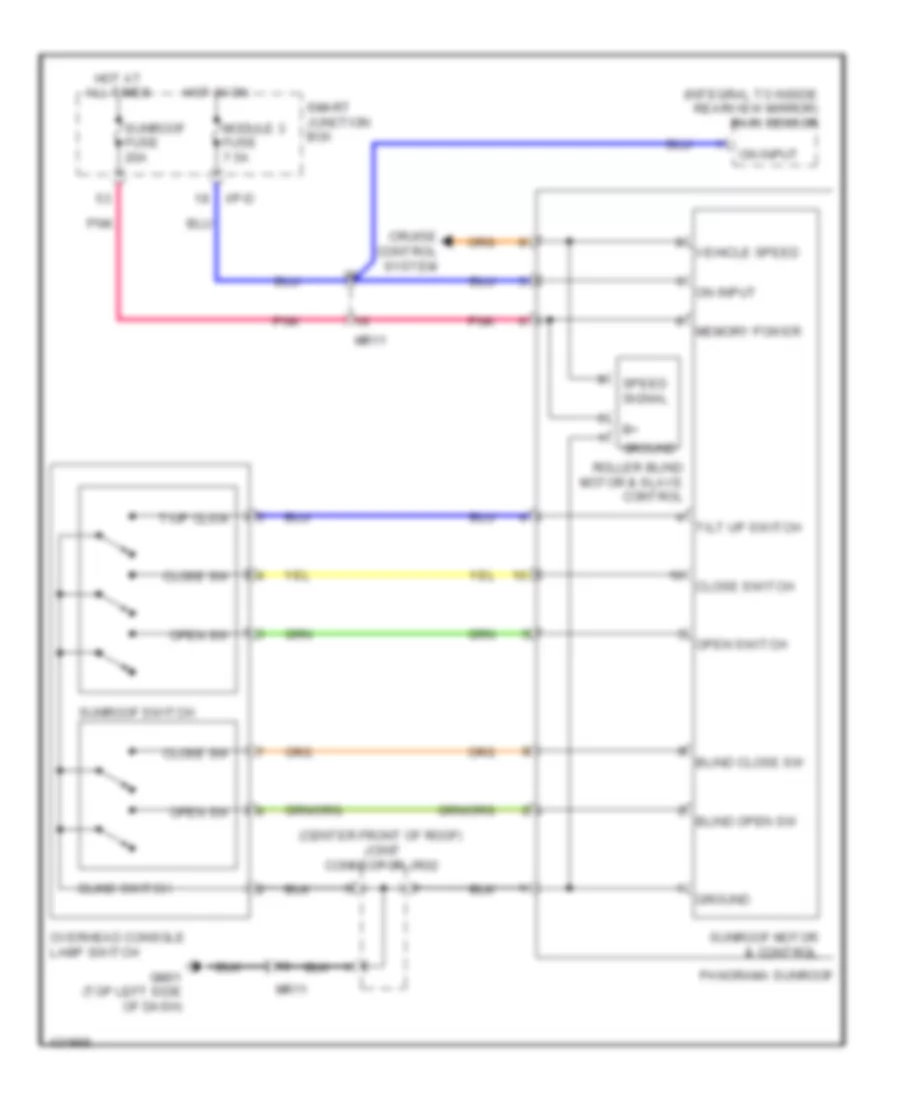
Cruise Control Wiring Diagram for Hyundai Azera 2014
List of elements for Cruise Control Wiring Diagram for Hyundai Azera 2014:
- (not used)
- (or pnk)
- (right rear wheelwell) auto head lamp leveling device module
- (top left side of dash) gm04
- (w/o esc) abs unit (w/ esc) esc unit
- 4p out
- A/v & navigation head unit
- Abs control module (w/o esc) esc control module (w/ esc) (left rear of engine compt)
- Accel pedal position sensor (above accelerator pedal assembly)
- Aps 1 gnd
- Aps 1 power
- Aps 1 sig
- Aps 2 gnd
- Aps 2 power
- Aps 2 sig
- Audio
- Brake light sw
- Brake test sw
- C-can hi
- C-can lo
- C-can transceiver
- Can hi
- Can lo
- Circuit
- Clg-b
- Clock spring
- Computer data lines
- Computer data lines system
- Cruise ind
- Data link connector (below left end of dash)
- Ec21
- Ef01
- Ef21
- Elg-a
- Em31
- Etc motor & throttle position sensor (on throttle body)
- Etc motor hi
- Etc motor lo
- Exterior lights system
- Fl sig
- Fl vcc
- Fr sig
- Fr vcc
- Ge05 (left rear of engine compt)
- Ge07 (right end of dash)
- Glg01 (front of left cylinder bank)
- Gm01 (top left side of dash)
- Gnd
- High
- Hot at all times
- Hot in on or start
- I/p-c
- I/p-d
- Ill (+)
- Ill (-)
- Instrument cluster
- Interior lights system
- Ips 5
- Ips 5 ctrl
- Ips control module
- J/c je03 (left side of dash)
- Joint block jm01 (top center of dash)
- Joint block jm02 (center of dash)
- Joint block jm02 (top center of dash)
- Leak current autocut device
- Left front wheel sensor (left front wheel hub assembly)
- Left high auto remote control switch
- Left rear wheel sensor (left rear wheel hub assembly)
- Low
- M-can transceiver
- M01-r
- M09-b
- M102-1
- M102-2
- M13-b
- M14-b
- Memory fuse 10a
- Memory power
- Mf21
- Micom
- Mm03
- Mm04
- Module fuse 10a
- Motor
- Mr11
- Multi-function switch
- Nca
- On/ start input
- Option
- Panorama sunroof
- Pcm (left side of engine compt)
- Pnk
- Red
- Right front wheel sensor (right front wheel hub assembly)
- Right high cruise/ steering wheel heater remote control switch
- Right rear wheel sensor (right rear wheel hub assembly)
- Rl sig
- Rl vcc
- Rr sig
- Rr vcc
- S gnd 1
- S gnd 2
- Set ind
- Sig 2
- Smart junction box
- Smart key control module (center of dash)
- Speedometer
- Steering wheel
- Stop lamp fuse 10a
- Stop lamp switch (above brake pedal, on bracket)
- Stop signal relay (left end of dash)
- System
- Tachometer
- Throttle position sensor
- Tps 1 sig
- Tps 2 sig
- Tps gnd
- Tps power
- Vss in
- W/ navigation
- W/ steering wheel heater
- W/o navigation
- W/o steering wheel heater
- Wheel speed
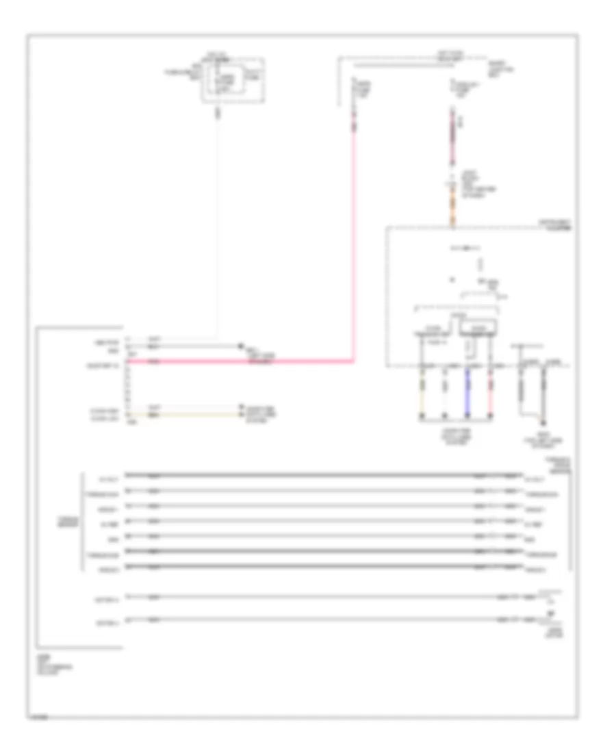
DEFOGGERS
Defoggers Wiring Diagram, with Auto Defogger (1 of 2) for Hyundai Azera 2014
List of elements for Defoggers Wiring Diagram, with Auto Defogger (1 of 2) for Hyundai Azera 2014:
- (right end
- B-can high
- B-can low
- Computer data lines system
- Defogger
- Deicer fuse 20a
- Deicer relay
- Driver power outside mirror
- E/r fuse & relay box (left side of engine compt)
- Ef11
- Fd11
- Fd21
- Front wiper deicer
- Ge07
- Gf02 (left "b" pillar)
- Gf03 (right "b" pillar)
- Ground
- Hot at all times
- Htd mirr fuse 10a
- I/p-a
- I/p-c
- I/p-d
- I/p-e
- Ips control module
- J/c jd01 (in driver's door)
- J/c jd02 (in passenger's door)
- Multi fuse
- Nca
- Of dash)
- Panel
- Passenger power outside mirror
- Quarter
- Rear
- Red
- Relay
- Rr htd
- Rr htd fuse 40a
- Rr htd rly ctrl
- Smart junction box
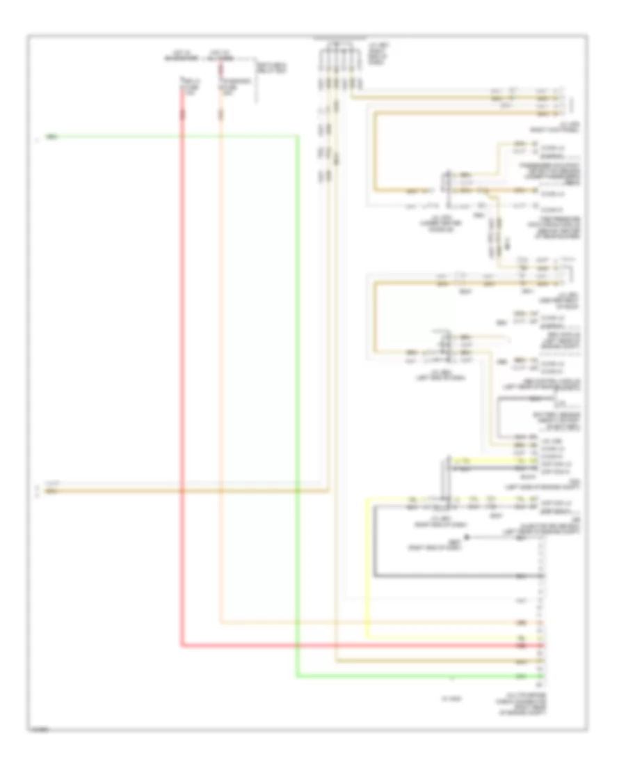
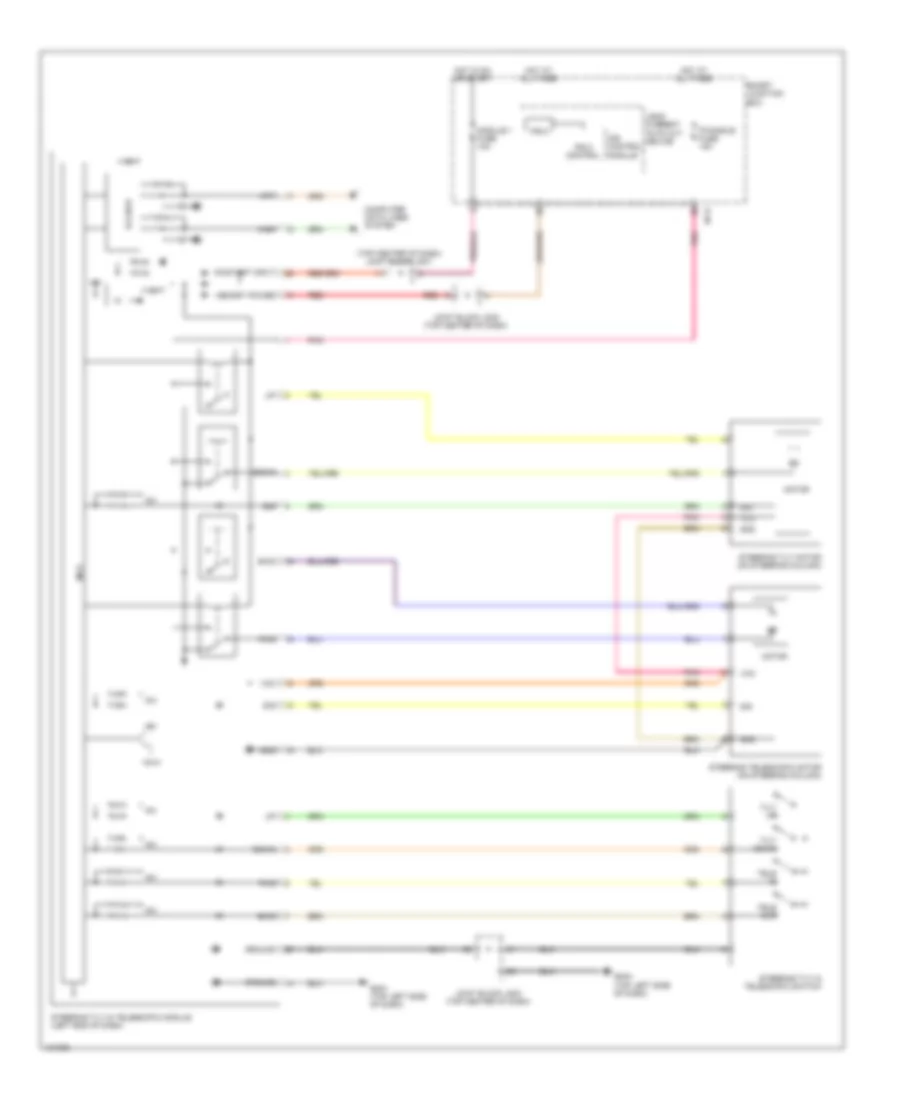
Defoggers Wiring Diagram, with Auto Defogger (2 of 2) for Hyundai Azera 2014
List of elements for Defoggers Wiring Diagram, with Auto Defogger (2 of 2) for Hyundai Azera 2014:
- A/c control module (center of dash)
- A/con fuse 7.5a
- Air conditioning system
- Auto defogger actuator
- Auto defogger actuator (upper right side of hvac unit)
- Auto defogger sensor
- Auto defogger snsr (+)
- Blower motor (+)
- Close
- Defogger switch
- Drain
- F/b
- Fet
- Gate
- Gm02 (right center of dash)
- Ground
- Hot at all times
- Hot in on
- Hot in on or start
- I/p-d
- I/p-e
- Ind
- Ips control module
- Joint block jm01 (top center of dash)
- Joint block jm02 (top center of dash)
- Joint block jm03 (top center
- Leak current autocut device
- M03-a
- M03-b
- Memory 1 fuse 10a
- Memory power
- Module 2 fuse 7.5a
- Mr11
- Of dash)
- Off
- On input
- On/start input
- Open
- Pnk
- Rear defogger switch input
- Red
- Smart junction box
- Snsr gnd
- Snsr pwr (+5v)
Defoggers Wiring Diagram, without Auto Defogger for Hyundai Azera 2014
List of elements for Defoggers Wiring Diagram, without Auto Defogger for Hyundai Azera 2014:
- (right center of dash)
- (right end
- A/c control module (center of dash)
- B-can high
- B-can low
- Computer data lines system
- Control
- Defogger
- Deicer fuse 20a
- Deicer relay
- Driver power outside mirror
- E/r fuse & relay box (left side of engine compt)
- Ef11
- Fd11
- Fd21
- Front wiper deicer
- Ge07
- Gf02 (left "b" pillar)
- Gf03 (right "b" pillar)
- Gm02
- Gnd
- Ground
- Hot at all times
- Htd mirr fuse 10a
- I/p-a
- I/p-c
- I/p-d
- I/p-e
- Ind
- Ips
- J/c jd01 (in driver's door)
- J/c jd02 (in passenger's door)
- M03-a
- M03-b
- Module
- Multi fuse
- Nca
- Of dash)
- Off
- Panel
- Passenger power outside mirror
- Quarter
- Rear
- Red
- Relay
- Rr defo sw i/p
- Rr htd
- Rr htd fuse 40a
- Rr htd rly ctrl
- Smart junction box
- Switch
ELECTRONIC POWER STEERING
Electronic Power Steering Wiring Diagram for Hyundai Azera 2014
List of elements for Electronic Power Steering Wiring Diagram for Hyundai Azera 2014:
- (left side
- 10a
- 5v ref
- Angle 1
- Angle 2
- C-can
- C-can high
- C-can low
- Computer data lines system
- E/r fuse & relay box
- E47
- Eps ind
- Ge11
- Gm04 (top left side of dash)
- Gnd
- High
- Hot at all times
- Hot in on or start
- I/p-d
- In volt
- Instrument cluster
- Joint block jm01 (top center of dash)
- Low
- M-can
- M26
- Mdps fuse 7.5a
- Mdps fuse 80a
- Mdps motor
- Mdps unit (on steering column)
- Mem pwr
- Micom
- Module 1 fuse
- Motor (+)
- Motor (-)
- Multi fuse
- Nca
- Of dash)
- On/start in
- Pnk
- Red
- S-gnd
- Smart junction box
- Torque & angle sensor
- Torque main
- Torque sensor
- Torque sub
- Transceiver
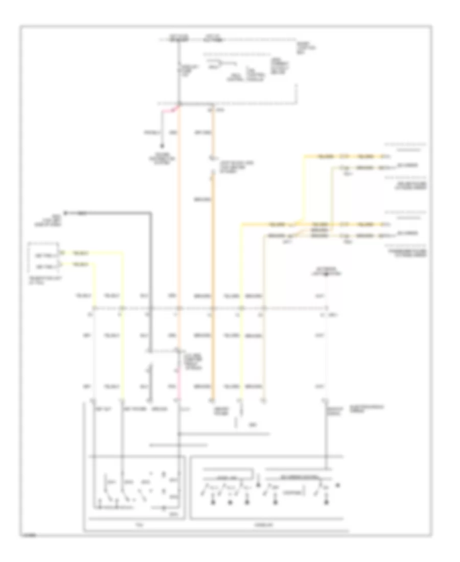
Power Tilt Steering Column Wiring Diagram for Hyundai Azera 2014
List of elements for Power Tilt Steering Column Wiring Diagram for Hyundai Azera 2014:
- (top center of dash) joint block jm01
- +5v
- +5va
- +vbat
- B-can ic
- Bwd
- Computer data lines system
- Down
- Fwd
- Gm01 (top left side of dash)
- Gm04 (top left side of dash)
- Gnd
- Ground
- High
- Hot at all times
- Hot in on or start
- I/p-d
- Ips 5
- Ips 5 control
- Ips control module
- Joint block jm02 (top center of dash)
- Joint block jm03 (top center of dash)
- Leak current auto cut device
- Low
- Mcu
- Memory power
- Module 1 fuse 10a
- Motor
- On/start input
- P/handle fuse 15a
- Pnk
- Red
- Sig
- Smart junction box
- Steering telescopic motor (on steering column)
- Steering tilt & telescopic module (left end of dash)
- Steering tilt & telescopic switch
- Steering tilt motor (on steering column)
- Tele in
- Tele out
- Tilt down
- Tilt up
- Vcc
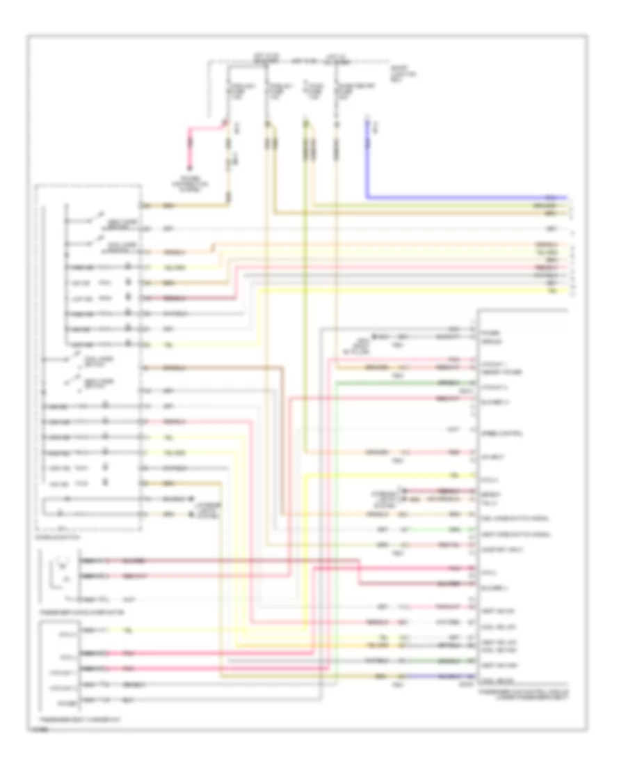
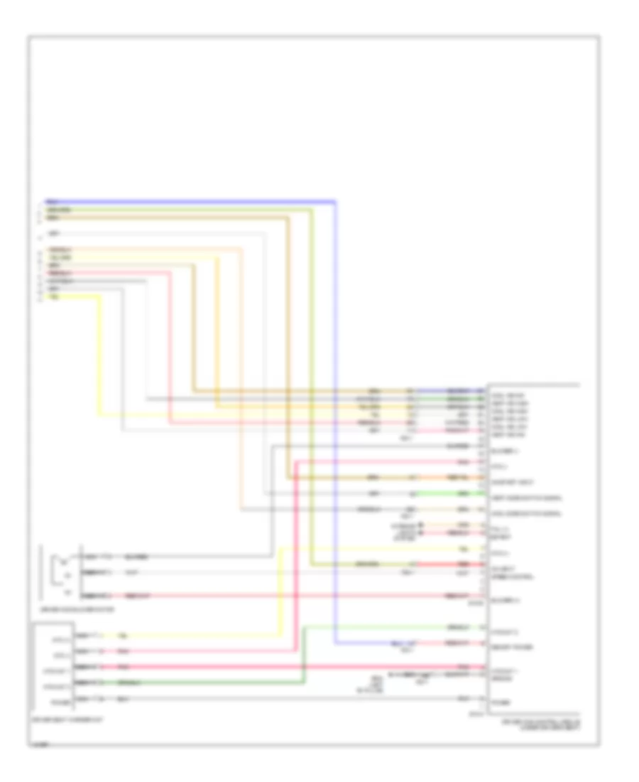
ENGINE PERFORMANCE
3.3L
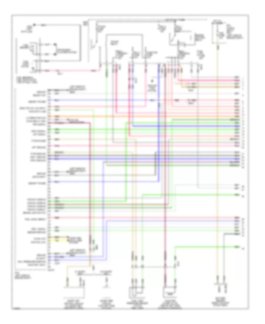
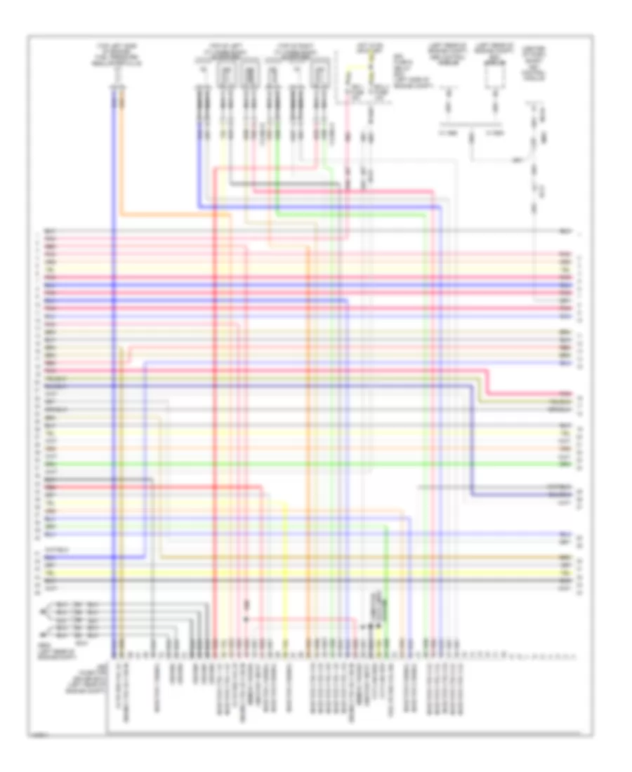
3.3L, Engine Performance Wiring Diagram (1 of 7) for Hyundai Azera 2014
List of elements for 3.3L, Engine Performance Wiring Diagram (1 of 7) for Hyundai Azera 2014:
- (left rear of
- (left rear of engine compt) ge05
- Alternator com
- Ams fuse 10a
- Aps 1 ground
- Aps 1 signal
- Aps 2 ground
- Aps 2 signal
- Apt ground
- Apt signal
- Brake lamp switch
- C-can low
- C/fan relay high
- Canister close valve (above left side of rear suspension)
- Ccp-can low
- Computer data lines system
- Cooling fans system
- Down shift
- E/r fuse & relay box (left side of engine compt)
- E/r-a
- E/r-b
- Ec21
- Ecu 1 fuse 30a
- Ecu 2 fuse 10a
- Ecu 3 fuse 15a
- Ecu/ sensor 1 fuse 15a
- Ecu/ sensor 2 fuse 10a
- Ef11
- Ef21
- Elg-a
- Em31
- Ems box
- Eng ctrl rly on input
- Engine compt) ge05
- Engine control relay
- F/pump fuse 20a
- F/pump relay
- Ftps ground
- Ftps power
- Fuel level sens 2
- Fuel pump motor
- Fuel sender
- Fuel sender & fuel pump motor (top of fuel tank)
- Fuel tank pressure sensor (top of fuel tank)
- Gf02 (left "b" pillar)
- Ground
- Hot at all times
- Ign coil fuse 20a
- Immo data line
- Immobilizer module (top left side of dash)
- Injector fuse 10a
- Instrument cluster system
- Lin line
- M13-a
- Memory power
- On/start input
- Pcm (left side of engine compt)
- Pnk
- Pos sw code s1
- Pos sw code s2
- Pos sw code s3
- Pos sw code s4
- Rail pressure snsr sig
- Red
- Rpm signal
- Select sw
- Sensor ground
- Smart key control module (w/ smart key) (center of dash)
- Snsr +
- Up shift
- W/ smart key
- W/o smart key
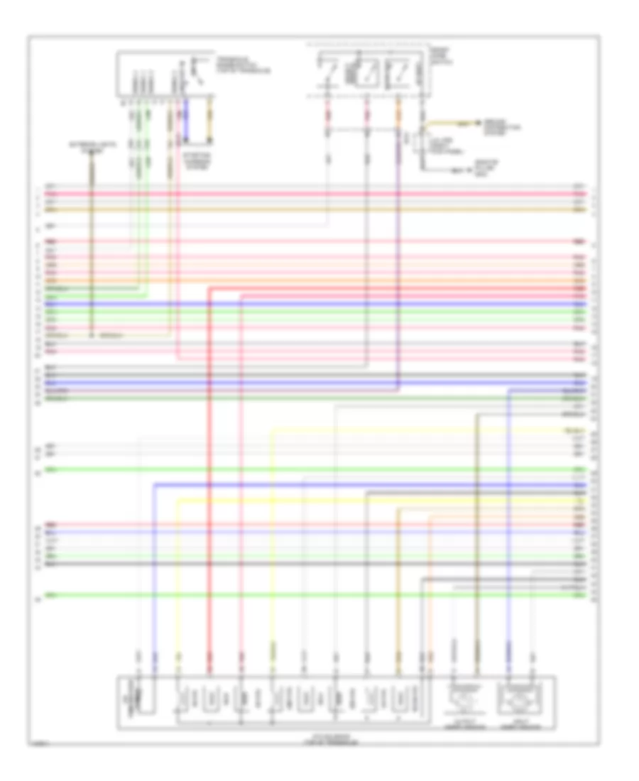
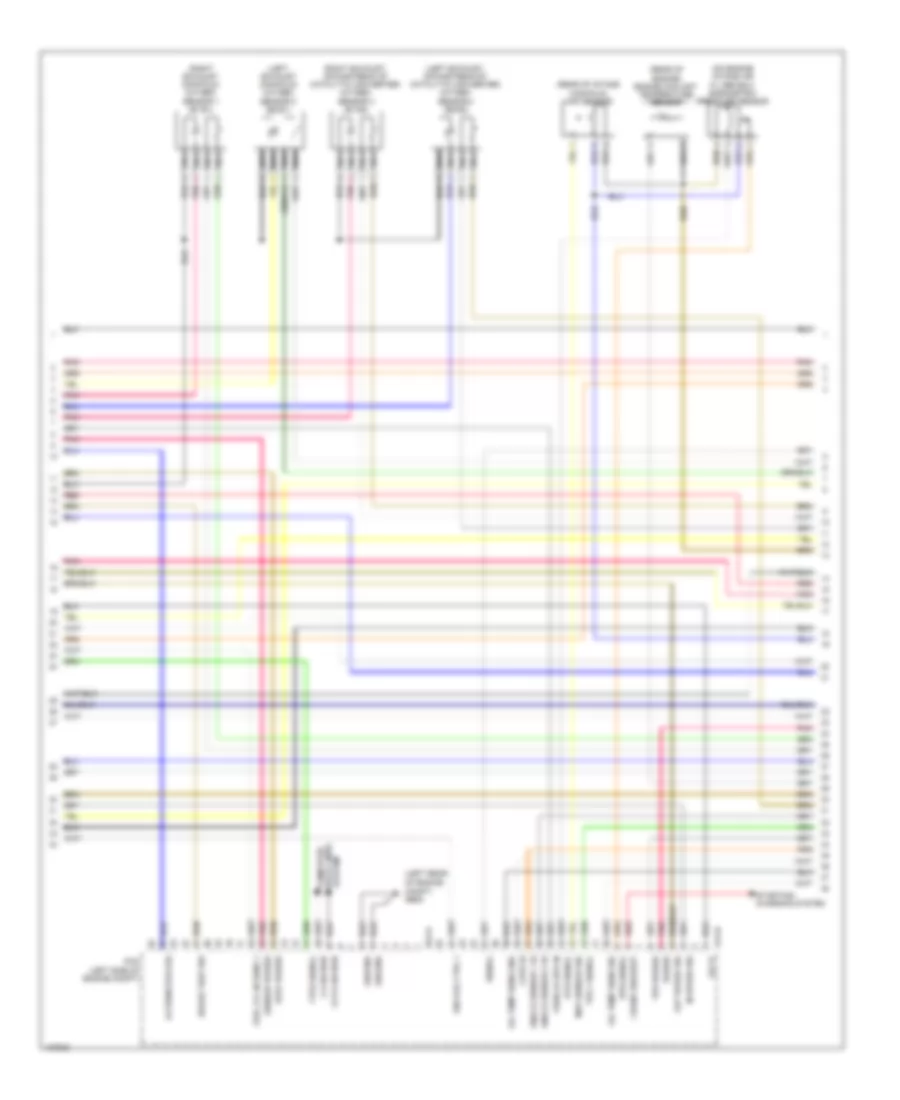
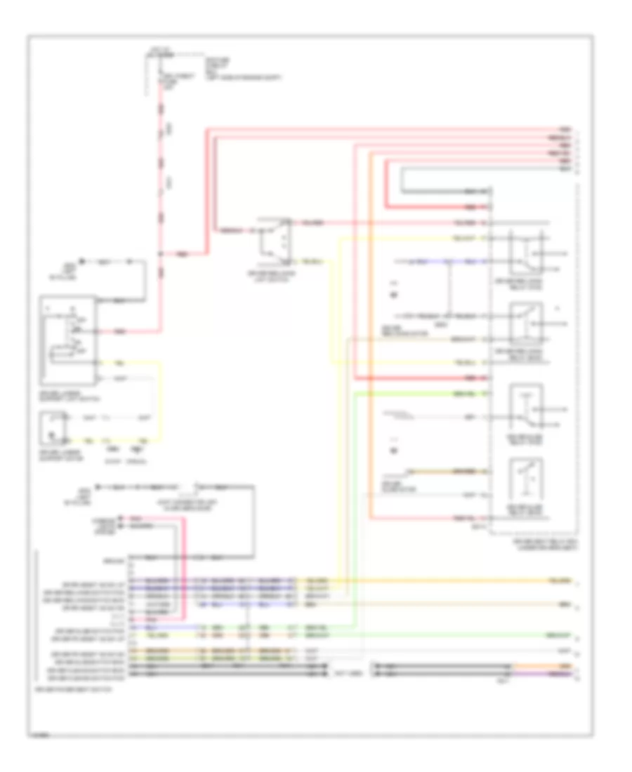
3.3L, Engine Performance Wiring Diagram (2 of 7) for Hyundai Azera 2014
List of elements for 3.3L, Engine Performance Wiring Diagram (2 of 7) for Hyundai Azera 2014:
- (right"b" pillar) gf03
- 26-vfs
- 35r-vfs
- Atm solenoid (top of transaxle)
- Down shift
- Ec21
- Ef21
- Exterior lights
- Ground distribution system
- Input speed sensor
- J/c jf05 (right kick panel)
- Line-vfs
- Od-vfs
- On/start in
- Output speed sensor
- P/n sw
- Pnk
- Red
- Select switch
- Sensor
- Signal 1
- Signal 2
- Signal 3
- Signal 4
- Sport mode switch
- Ss-a
- Ss-b
- Starting/ charging system
- System
- T/con-vfs
- Temperature oil
- Transaxle range switch (top of transaxle)
- Ud-vfs
- Up shift
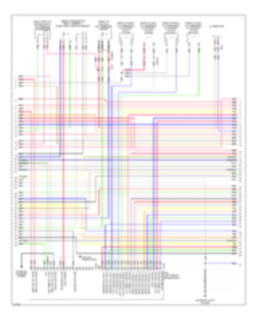
3.3L, Engine Performance Wiring Diagram (3 of 7) for Hyundai Azera 2014
List of elements for 3.3L, Engine Performance Wiring Diagram (3 of 7) for Hyundai Azera 2014:
- (above accelerator pedal assembly) accel pedal position sensor
- (front of fuel rail) rail pressure sensor
- (front of left cylinder bank) oil control valve 2 (intake)
- (front of left cylinder bank) oil control valve 4 (exhaust)
- (front of right cylinder bank) oil control valve 1 (intake)
- (front of right cylinder bank) oil control valve 3 (exhaust)
- (right front of engine compt)
- A/c pressure transducer
- Alternator
- Aps 2 power
- C/fan relay low
- Ccv
- Clg-b
- Clginj-b
- Clgocv
- Cooling fans system
- Cvvt exhaust bank 1
- Cvvt exhaust bank 2
- Cvvt intake bank 1
- Cvvt intake bank 2
- Ec21
- Elg-a
- Eng ctrl rly ctrl
- Eng ctrl rly on in
- Etc motor (low)
- Exterior lights system
- Fprv control
- Fuel pump rly ctrl
- Ignition coil ctrl 2
- Ignition coil ctrl 4
- Ignition coil ctrl 6
- Injector control 1
- Injector control 2
- Injector control 3
- Injector control 4
- Injector control 5
- Injector control 6
- Lin diag data line
- Nca
- Oxy snsr 1 heater
- Oxy snsr 2 heater
- Oxy snsr 3 heater
- Oxy snsr 4 heater
- Pcm (left side of engine compt)
- Pnk
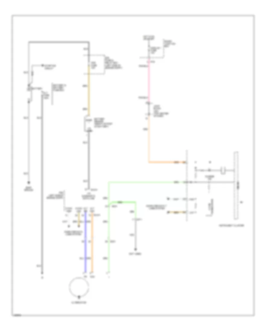
- Red
- Start over run
- Starting/ charging system
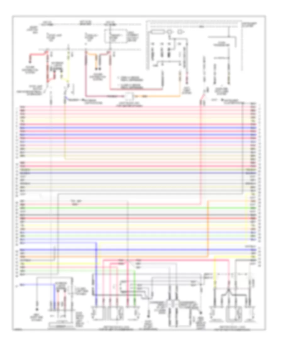
3.3L, Engine Performance Wiring Diagram (4 of 7) for Hyundai Azera 2014
List of elements for 3.3L, Engine Performance Wiring Diagram (4 of 7) for Hyundai Azera 2014:
- Anti- theft system
- C-can transceiver
- Circuit
- Clgign
- Close w/ brake
- Computer data lines system
- Condenser 1 (front of left cylinder bank)
- Condenser 2 (front of left cylinder bank)
- Cruise ind
- Ec21
- Em31
- Engine check ind
- Exterior lights system
- Fuel input
- Ge05 (left rear of engine compt)
- Ge07 (right end of dash)
- Glg01 (front of left cylinder bank)
- High
- Hot at all times
- Hot in on or start
- I/p-c
- I/p-d
- Ignition coils 1, 3 & 5 (top of right cylinder bank)
- Ignition coils 2, 4 & 6 (top of left cylinder bank)
- Immo ind
- Instrument cluster
- Instrument cluster system
- J/c je03 (left side of dash)
- Joint block jm01 (top center of dash)
- Leak current autocut device
- Low
- Mcu
- Memory 1 fuse 10a
- Module 1 fuse 10a
- Nca
- Open w/ brake
- Pedal depressed
- Pnk
- Power distribution system
- Red
- Set ind
- Smart junction box
- Stop lamp fuse 10a
- Stop lamp switch (above brake pedal, on bracket)
- Stop signal relay (left end of dash)
3.3L, Engine Performance Wiring Diagram (5 of 7) for Hyundai Azera 2014
List of elements for 3.3L, Engine Performance Wiring Diagram (5 of 7) for Hyundai Azera 2014:
- (center of dash) smart key control module
- (left rear of engine compt) abs control module
- (left rear of engine compt) esc module
- (top left side of engine) fuel pressure regulator valve
- (top of left cylinder bank) injectors
- (top of right cylinder bank) injectors
- Ccp can high
- Ccp can low
- Clginj-a
- Clginj-b
- E/r fuse & relay box (left side of engine compt)
- Ec21
- Ecu 4 fuse 10a
- Em31
- Engine ctrl rly on in
- Fu pr reg val hi
- Fu pr reg val lo
- Fuel pr reg val sig
- Ge05 (left rear of engine compt)
- Ground
- Idb (injector driver box) (left rear of engine compt)
- Ign 1 fuse 15a
- Injector 1 signal
- Injector 2 signal
- Injector 3 signal
- Injector 4 signal
- Injector 5 signal
- Injector 6 signal
- Injector ctrl 1 hi
- Injector ctrl 1 lo
- Injector ctrl 2 hi
- Injector ctrl 2 lo
- Injector ctrl 3 hi
- Injector ctrl 3 lo
- Injector ctrl 4 hi
- Injector ctrl 4 lo
- Injector ctrl 5 hi
- Injector ctrl 5 lo
- Injector ctrl 6 hi
- Injector ctrl 6 lo
- M13-b
- Memory power
- Nca
- On/start input
- Pnk
- Red
- System data lines computer
- W/ abs
- W/ esc
3.3L, Engine Performance Wiring Diagram (6 of 7) for Hyundai Azera 2014
List of elements for 3.3L, Engine Performance Wiring Diagram (6 of 7) for Hyundai Azera 2014:
- (left exhaust manifold) oxygen sensor 2 (b2/s1)
- (left exhaust, downstream of catalytic converter) oxygen sensor 4 (b2/s2)
- (left rear
- (on engine intake air filter box) barometric pressure sensor
- (rear of engine) engine coolant temperature sensor
- (rear of intake manifold) map sensor
- (right exhaust manifold) oxygen sensor 1 (b1/s1)
- (right exhaust, downstream of catalytic converter) oxygen sensor 3 (b1/s2)
- Alternator (fr)
- Aps1 power
- Ats signal
- Bps signal
- Brake test sw
- C-can high
- Ccp-can high
- Ckps hi
- Clg-b
- Crank request
- Elg-a
- Ftps signal
- Fuel lvl in sens 1
- Ground
- Ign coil ctrl 1
- In speed sig
- Knock sensor 1 hi
- Knock sensor 2 hi
- Map sensor sig
- Nca
- Od vf
- Of engine compt) ge05
- Oil temp sens gnd
- Oil temp sens sig
- Out speed sig
- Pcm (left side of engine compt)
- Pnk
- Power
- Red
- Sensor power
- Signal
- Starting/ charging system
- System data lines computer
- Tps 1 signal
- Tps power
- Vehicle spd in
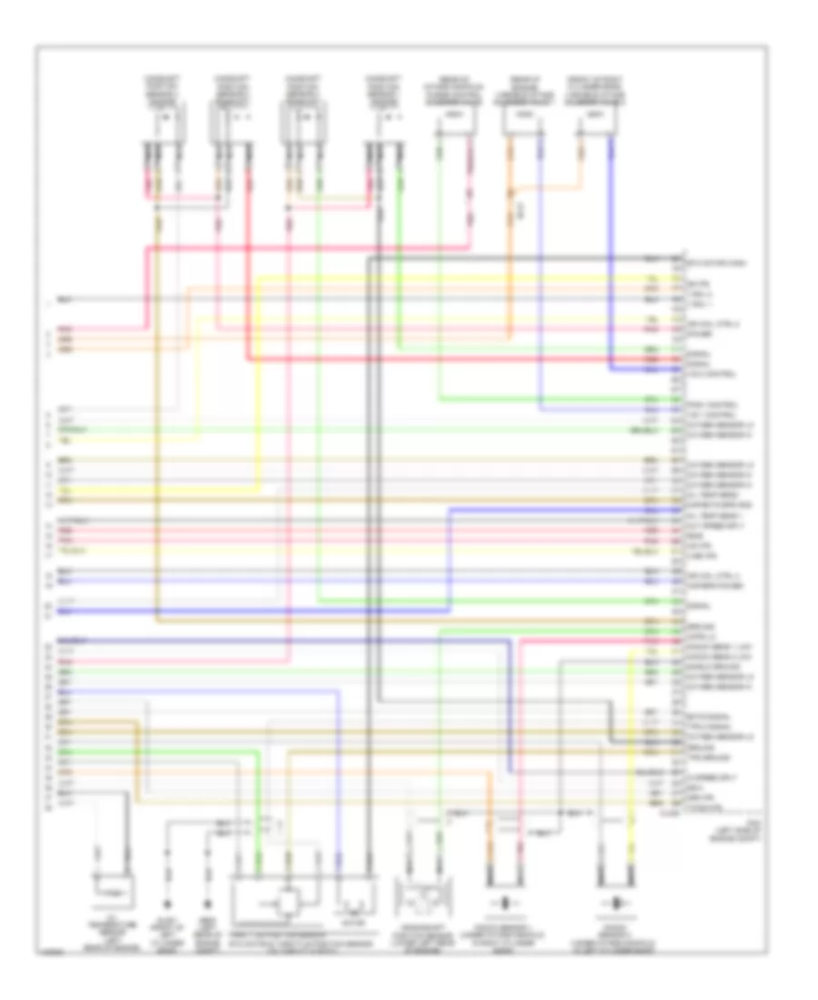
3.3L, Engine Performance Wiring Diagram (7 of 7) for Hyundai Azera 2014
List of elements for 3.3L, Engine Performance Wiring Diagram (7 of 7) for Hyundai Azera 2014:
- (front of right cylinder bank)
- (rear of engine) variable intake solenoid valve 1
- (rear of intake manifold)
- 26-vfs
- 35r-vfs
- Camshaft position sensor 1 (intake)
- Camshaft position sensor 2 (exhaust)
- Camshaft position sensor 3 (intake)
- Camshaft position sensor 4 (exhaust)
- Ckps lo
- Clg-b
- Crankshaft position sensor (lower left rear of engine)
- Ec21
- Ects signal
- Etc motor & throttle position sensor (on throttle body)
- Etc motor (high)
- Ge05 (left rear of engine compt)
- Glg01 (front of left cylinder bank)
- Ground
- Ign coil ctrl 3
- Ign coil ctrl 5
- In speed sply
- Knock sens 1 low
- Knock sens 2 low
- Knock sensor 1 (under intake manifold, in right cylinder bank)
- Knock sensor 2 (under intake manifold, in left cylinder bank)
- Line-vfs
- Map/bps power
- Map/ects bps gnd
- Motor
- Nca
- Oil temp sens +
- Oil temp sens -
- Oil temperature sensor (left rear of engine)
- Out speed sply
- Oxygen sensor hi
- Oxygen sensor lo
- Pcm (left side of engine compt)
- Pcsv control
- Pnk
- Power
- Purge control solenoid valve
- Red
- Shield ground
- Signal
- Ss-a
- Ss-b
- T/con-vfs
- Throttle position sensor
- Tps 2 signal
- Tps ground
- Ud-vfs
- V-sol 1
- V-sol 2
- Variable intake solenoid valve 2
- Vis 1 control
- Vis 2 control
EXTERIOR LIGHTS
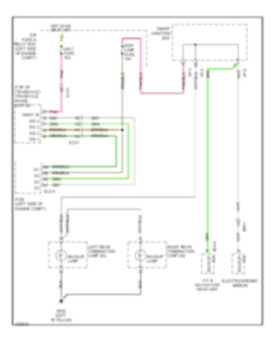
Backup Lamps Wiring Diagram for Hyundai Azera 2014
List of elements for Backup Lamps Wiring Diagram for Hyundai Azera 2014:
- (top of transaxle) transaxle range switch
- A/v & navigation head unit
- B/up lamp fuse 10a
- Backup lamp
- E/r fuse & relay box (left side of engine compt)
- Ec21
- Electrochromic mirror
- Elg-a
- Gf02 (left "b" pillar)
- Hot in on or start
- I/p-a
- I/p-c
- I/p-d
- Ign 1 fuse 15a
- Left rear combination lamp (in)
- M14-a sig backup
- Mr11
- On/st in
- Pcm (left side of engine compt)
- Pnk
- Right rear combination lamp (in)
- Sig 1
- Sig 2
- Sig 3
- Sig 4
- Sig backup
- Smart junction box
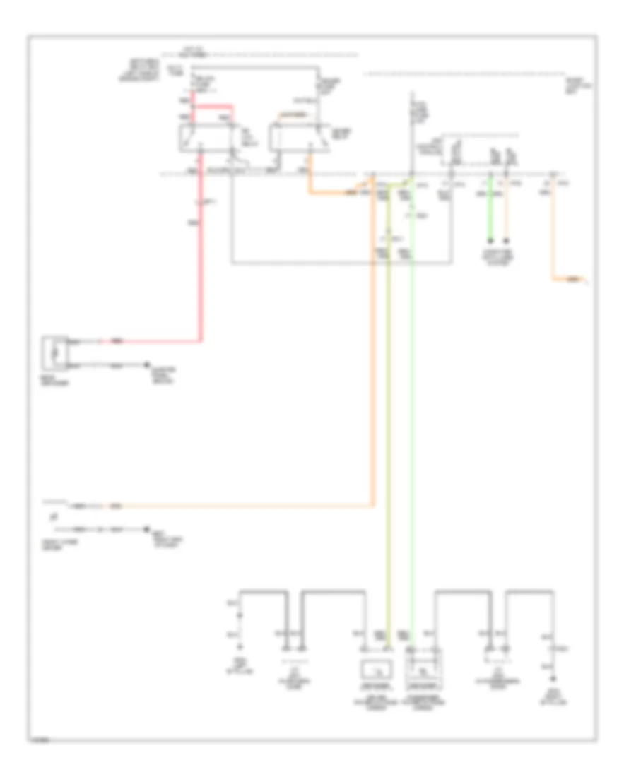
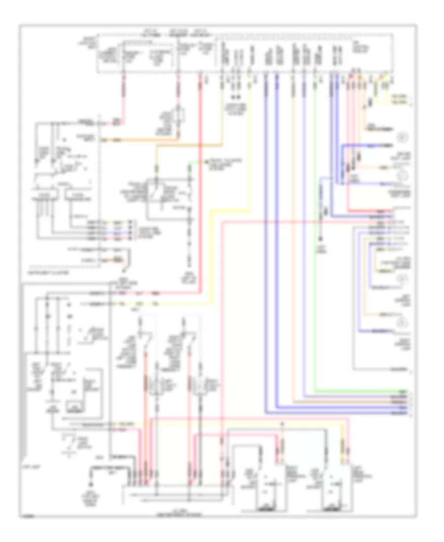
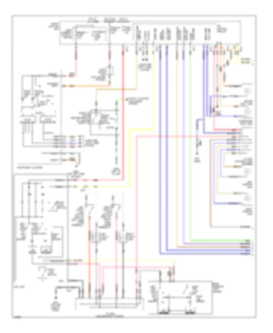
Exterior Lamps Wiring Diagram, with ESC (1 of 2) for Hyundai Azera 2014
List of elements for Exterior Lamps Wiring Diagram, with ESC (1 of 2) for Hyundai Azera 2014:
- (center of dash)
- (in
- (in driver's
- (top center of dash) joint block jm02
- A/c control module
- Amp1
- Amp2
- Arisu lt control
- Arisu lt1
- Arisu lt2
- Auto
- B-can
- C-can
- Can-high
- Can-low
- Computer data lines
- Computer data lines system
- Control module
- Door) j/c jd01
- Door) j/c jd02
- Driver
- Fd11
- Fd21
- Ge01 (left front of engine compt)
- Ge02 (right side of engine compt)
- Gf02 (left "b" pillar)
- Gf03 (right "b" pillar)
- Gm04 (top left side of dash)
- Gnd
- Gnd 1
- Gnd 2
- Hazard switch
- Hazard switch signal
- High
- High beam ind
- Hot at all times
- Hot in on or start
- I/p-a
- I/p-c
- I/p-d
- I/p-e
- Instrument cluster
- Instrument cluster speaker
- Ips
- Ips 2
- Ips 2 control
- Ips 5
- Ips 5 control
- Joint block jm01 (top center of dash)
- Joint block jm03 (top center of dash)
- Leak current autocut device
- Left
- Left headlamp
- Left rear combination lamp (out)
- Left turn ind
- Light switch
- Low
- M/f sw ecu
- M03-a
- Memory fuse 10a
- Memory power
- Micom
- Module 1 fuse 10a
- Multi-function switch
- Nca
- Off
- Parking lamp
- Passenger
- Passenger's
- Pnk
- Power outside mirror
- Red
- Right
- Right headlamp
- Right turn ind
- Side marker lamp
- Smart junction box
- Sound chip 80hm 1w
- Stop lamp
- System
- Tail lamp
- Tail on ind
- Transceiver c-can
- Transceiver m-can
- Turn lamp
- Turn signal lamp switch
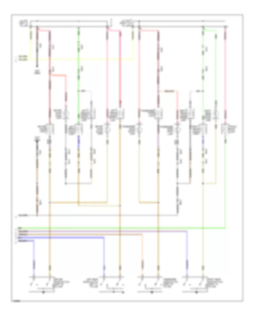
Exterior Lamps Wiring Diagram, with ESC (2 of 2) for Hyundai Azera 2014
List of elements for Exterior Lamps Wiring Diagram, with ESC (2 of 2) for Hyundai Azera 2014:
- "c"
- (no)
- (not used)
- (right
- Backup lamp
- Backup lamps circuit
- Brake light sw
- Brake switch
- Brake test sw
- Circuit
- E/r fuse & relay box (left side of engine compt)
- Elg-a
- Em31
- Esc module (left rear of engine compt)
- Ge07 (right end of dash)
- Gf02 (left "b" pillar)
- Gf03 (right "b" pillar)
- High mounted stop lamp
- High mounted stop lamp filter
- Hot at all times
- I/p-c
- I/p-d
- Ips control module
- J/c je03 (left side of dash)
- Left rear combination lamp (in)
- License lamp
- License lamp & trunk lid handle switch
- M13-b
- Mf11
- Nca
- Pcm (left side of engine compt)
- Pillar)
- Pnk
- Red
- Right rear combination lamp (in)
- Right rear combination lamp (out)
- Side marker lamp
- Smart junction box
- Smart key control module (center of dash)
- Stop lamp
- Stop lamp fuse 10a
- Stop lamp fuse 15a
- Stop lamp relay
- Stop lamp switch (above brake pedal, on bracket)
- Stop signal relay (left end of dash)
- Tail lamp
- Turn lamp
Exterior Lamps Wiring Diagram, without ESC (1 of 2) for Hyundai Azera 2014
List of elements for Exterior Lamps Wiring Diagram, without ESC (1 of 2) for Hyundai Azera 2014:
- (center of dash)
- (in
- (in driver's
- (top center of dash) joint block jm02
- 80hm 1w sound chip
- A/c control module
- Amp1
- Amp2
- Arisu lt control
- Arisu lt1
- Arisu lt2
- Auto
- B-can
- C-can
- C-can transceiver
- Can-high
- Can-low
- Computer data lines
- Computer data lines system
- Door) j/c jd01
- Door) j/c jd02
- Driver
- Fd11
- Fd21
- Ge01 (left front of engine compt)
- Ge02 (right side of engine compt)
- Gf02 (left "b" pillar)
- Gf03 (right "b" pillar)
- Gm04 (top left side of dash)
- Gnd
- Gnd 1
- Gnd 2
- Hazard switch
- Hazard switch signal
- High
- High beam ind
- Hot at all times
- Hot in on or start
- I/p-a
- I/p-c
- I/p-d
- I/p-e
- Instrument cluster
- Instrument cluster speaker
- Ips 2
- Ips 2 control
- Ips 5
- Ips 5 control
- Ips control module
- Joint block jm01 (top center of dash)
- Joint block jm03 (top center of dash)
- Leak current autocut device
- Left
- Left headlamp
- Left rear combination lamp (out)
- Left turn ind
- Light switch
- Low
- M-can transceiver
- M/f sw ecu
- M03-a
- Memory fuse 10a
- Memory power
- Micom
- Module 1 fuse 10a
- Multi-function switch
- Nca
- Off
- Parking lamp
- Passenger
- Passenger's
- Pnk
- Power outside mirror
- Red
- Right
- Right headlamp
- Right turn ind
- Side marker lamp
- Smart junction box
- Stop lamp
- System
- Tail lamp
- Tail on ind
- Turn lamp
- Turn signal lamp switch
Exterior Lamps Wiring Diagram, without ESC (2 of 2) for Hyundai Azera 2014
List of elements for Exterior Lamps Wiring Diagram, without ESC (2 of 2) for Hyundai Azera 2014:
- "c"
- (no)
- (not used)
- (right
- Abs control module (left rear of engine compt)
- Backup lamp
- Backup lamps circuit
- Brake light sw
- Brake switch
- Brake test sw
- Circuit
- E/r fuse & relay box (left side of engine compt)
- Elg-a
- Em31
- Ge07 (right end of dash)
- Gf02 (left "b" pillar)
- Gf03 (right "b" pillar)
- High mounted stop lamp
- High mounted stop lamp filter
- Hot at all times
- I/p-c
- I/p-d
- Ips control module
- J/c je03 (left side of dash)
- Left rear combination lamp (in)
- License lamp
- License lamp & trunk lid handle switch
- M13-b
- Mf11
- Nca
- Pcm (left side of engine compt)
- Pillar)
- Pnk
- Red
- Right rear combination lamp (in)
- Right rear combination lamp (out)
- Side marker lamp
- Smart junction box
- Smart key control module (center of dash)
- Stop lamp
- Stop lamp fuse 10a
- Stop lamp fuse 15a
- Stop lamp switch (above brake pedal, on bracket)
- Stop signal relay (left end of dash)
- Tail lamp
- Turn lamp
GROUND DISTRIBUTION
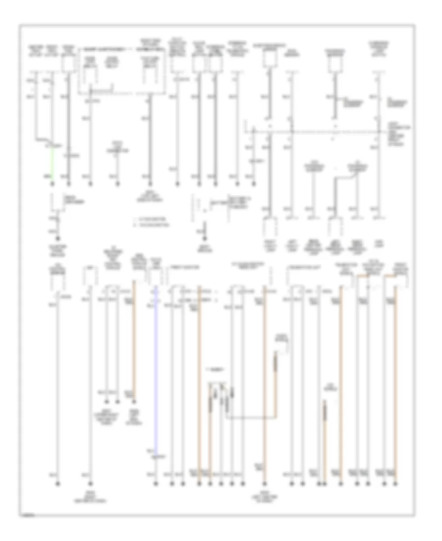
Ground Distribution Wiring Diagram (1 of 5) for Hyundai Azera 2014
List of elements for Ground Distribution Wiring Diagram (1 of 5) for Hyundai Azera 2014:
- (if equipped) smart key control module
- (right end of dash)
- A/c control module
- A/v & navigation head unit
- A/v & navigation head unit shield
- Audio
- Audio shield
- Aux & usb jack
- Battery
- Battery & battery fuse box
- Body ground
- Center tray outlet
- Crash pad switch
- Data link connector
- Door lock relay
- Door unlock relay
- Electrochromic mirror
- Fet
- Front monitor
- Front monitor shield
- Front tray outlet
- Glove box lamp switch
- Gm01 (top left side of dash)
- Gm02 (right center of dash)
- Gm03 (left center of dash)
- Gm06 (left end of dash)
- Gm07 (upper right center of dash)
- I/p-d
- Icm relay box
- Joint connector jr02 (center front of roof)
- Left rear personal lamp
- Left vanity lamp
- M01-r
- M09-b
- M09-g
- M13-a
- M14-b
- M14-g
- M69
- M69-g
- M70
- M70-g
- M78
- M78-g
- Map lamp
- Mic shield
- Mm01
- Mm02
- Mo3-b
- Mr11
- Multi function switch (remote control)
- Nca
- Overhead console lamp switch
- Panorama sunroof
- Quarter panel ground
- Rain sensor
- Rear center personal lamp
- Rear defogger
- Right rear personal lamp
- Right vanity lamp
- Smart junction box
- Srs control module shield
- Steering tilt& telescopic module
- Steering wheel heater
- Telematics unit
- Telematics unit shield
- Two turn unlock relay
- W/ navigation
- W/ panorama sunroof
- W/o navigation
- W/o panorama sunroof
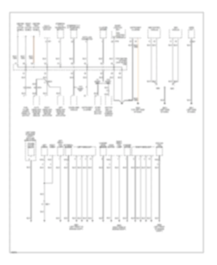
Ground Distribution Wiring Diagram (2 of 5) for Hyundai Azera 2014
List of elements for Ground Distribution Wiring Diagram (2 of 5) for Hyundai Azera 2014:
- (left side of engine compt) e/r fuse & relay box
- (top center of dash) joint block jm03
- Abs
- Abs control module
- Auto headlamp leveling device module
- Center tray outlet shield
- Cluster ionizer
- Cooling fan motor
- Data link connector
- E47
- Ee11
- Em21
- Esc
- Esc module
- External buzzer
- Front tray outlet shield
- Fuel filler door & trunk lid switch
- Ge01 (left front of engine compt)
- Ge02 (right side of engine compt)
- Ge08 (left front of engine compt)
- Ge10 (left side of dash)
- Ge11 (left side of dash)
- Gm04 (top left side of dash)
- Hood switch
- I/p-e
- Ignition key ill & door warning switch
- Immobilizer module
- Instrument cluster
- Ips control module
- Left front fog lamp
- Left headlamp
- Left headlamp leveling device actuator
- Left horn
- M01
- Mdps unit
- Mf21
- Mm02
- Multi- function switch
- Nca
- Power outlet relay
- Right front fog lamp
- Right headlamp
- Right headlamp leveling device actuator
- Right horn
- Smart junction box
- Start stop button switch
- Steering tilt & telescopic module
- Steering tilt & telescopic switch
- W/ smart key
- W/o smart key
- Washer level sensor
- Washer motor
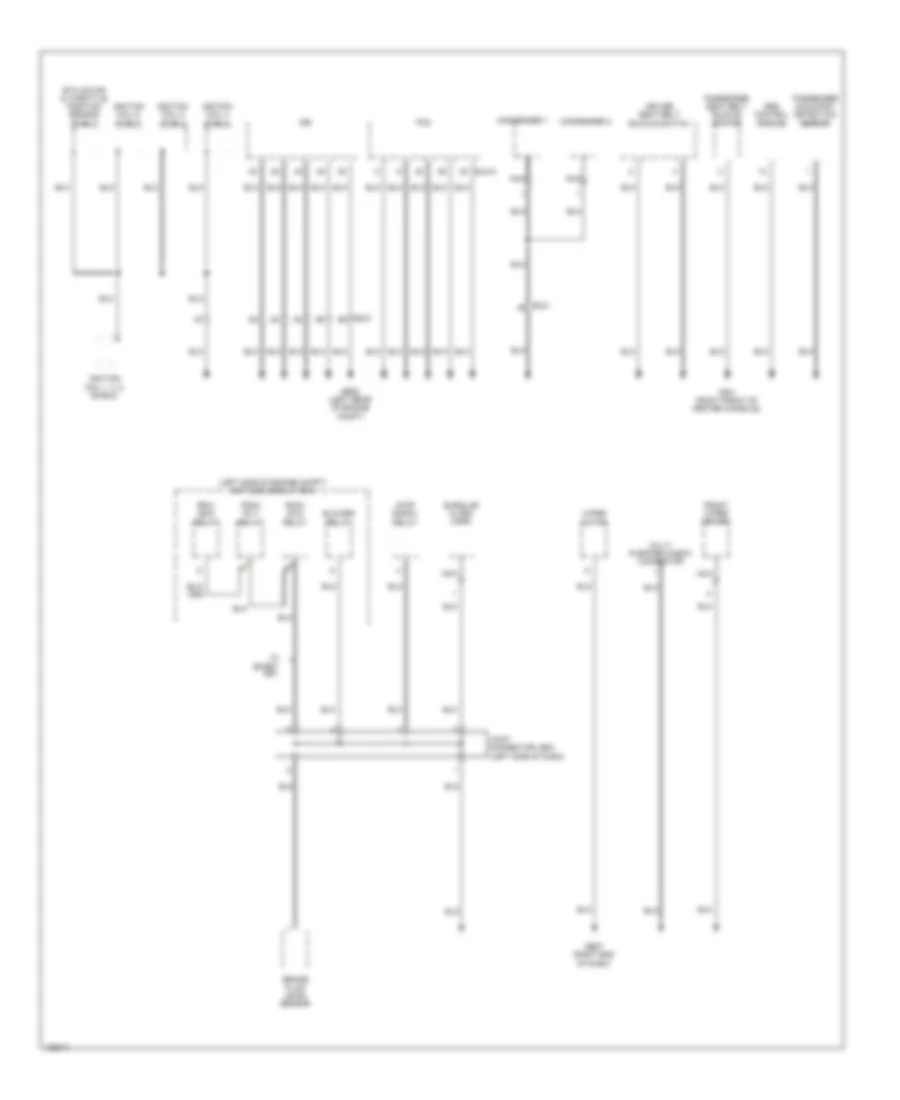
Ground Distribution Wiring Diagram (3 of 5) for Hyundai Azera 2014
List of elements for Ground Distribution Wiring Diagram (3 of 5) for Hyundai Azera 2014:
- (left side of engine compt) e/r fuse & relay box
- Blower relay
- Brake fluid level sensor
- Burglar alarm horn
- Condenser 1
- Condenser 2
- Driver seat belt buckle switch
- Ec21
- Elg-a
- Etc motor & throttle position sensor shield
- Front wiper deicer
- Ge05 (left rear of engine compt)
- Ge07 (right end of dash)
- Gf01 (right front of center console)
- Idb
- Ignition coil 1, 3, 5 shield
- Ignition coil 2 shield
- Ignition coil 4 shield
- Ignition coil 6 shield
- Joint connector je03 (left side of dash)
- Multi purpose check connector
- Nca
- Passenger occupant detection sensor
- Passenger seat belt buckle switch
- Pcm
- Pdm1 (acc) relay
- Pdm2 (ig 1) relay
- Pdm3 (ig 2) relay
- Srs control module
- Stop signal relay
- W/ smart key
- Wiper motor
Ground Distribution Wiring Diagram (4 of 5) for Hyundai Azera 2014
List of elements for Ground Distribution Wiring Diagram (4 of 5) for Hyundai Azera 2014:
- (under driver's
- (w/ seat warmer) left rear power window switch
- 8 way
- Amp
- Ccs
- Console box lamp
- Console switch
- Dd11
- Dd31
- Driver ccs control module
- Driver door lock actuator
- Driver door module
- Driver ims module
- Driver lumbar support limit switch
- Driver power outside mirror
- Driver power seat switch
- Driver safety power window module
- Driver seat relay box
- Driver seat warmer module
- Driver smart key outside handle
- F02-a
- Fd11
- Fd31
- Ff01
- Fr01
- Fs11
- Fuel filler actuator
- Fuel sender & fuel pump motor
- Gf02 (left "b" pillar)
- Gf04 (left "c" pillar)
- Gf05 (right "c" pillar)
- Ground (power)
- Ground (sig)
- I/p-f
- Ims
- Ips control module
- Joint connector jd01 (in driver's door)
- Joint connector js01 (under driver's seat)
- Left rear combination lamp (in)
- Left rear combination lamp (out)
- Left rear door lock actuator
- Left rear parking assist sensor
- Left rear parking assist sensor (center)
- Left rear seat warmer
- License lamp & trunk lid handle switch
- Nca
- Rear power outlet
- Right rear combination lamp (in)
- Right rear parking assist sensor
- Right rear parking assist sensor (center)
- S04-b
- S04-d
- S07-a
- S07-b
- S07-c
- S10a
- Seat warmer
- Seat)
- Smart junction box
- Tire pressure monitoring module
- Trunk lid motor
- W/ smart key
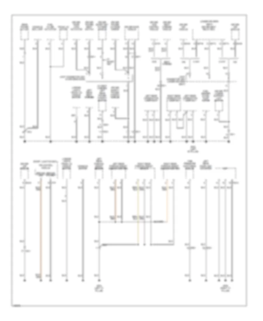
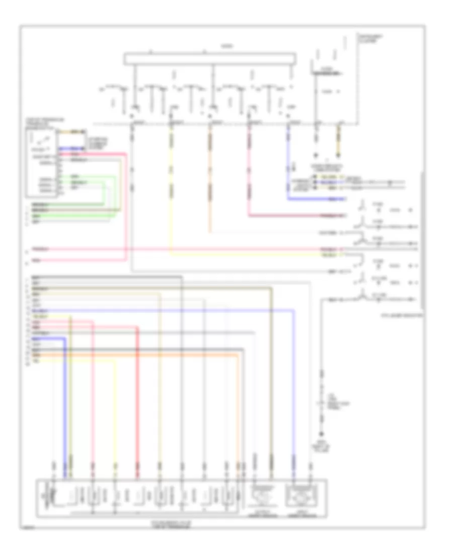
Ground Distribution Wiring Diagram (5 of 5) for Hyundai Azera 2014
List of elements for Ground Distribution Wiring Diagram (5 of 5) for Hyundai Azera 2014:
- (under passenger's
- 4-way
- 8-way
- Atm lever indicator
- Ccs
- Dd21
- Dd41
- Etc motor & throttle position sensor shield
- Fd21
- Fd41
- Fs21
- Gf03 (right "b" pillar)
- Glg01 (front of left cylinder bank)
- High mounted stop lamp
- Ignition coil 1, 3, 5 shield
- Ignition coil 2 shield
- Ignition coil 4 shield
- Ignition coil 6 shield
- Joint connector jd02 (in passenger's door)
- Joint connector jf05 (right kick panel)
- Joint connector js02 (under passenger's seat)
- Nca
- Passenger ccs control module
- Passenger door lock actuator
- Passenger door module
- Passenger power outside mirror
- Passenger power seat switch
- Passenger safety power window module
- Passenger seat relay box
- Passenger seat warmer module
- Passenger smart key outside handle
- Rf receiver
- Right rear combination lamp (out)
- Right rear door lock actuator
- Right rear power window switch
- Right rear seat warmer
- S27
- S27-a
- S27-b
- S30-a
- Seat warmer
- Seat)
- Sport mode switch
- W/ smart key
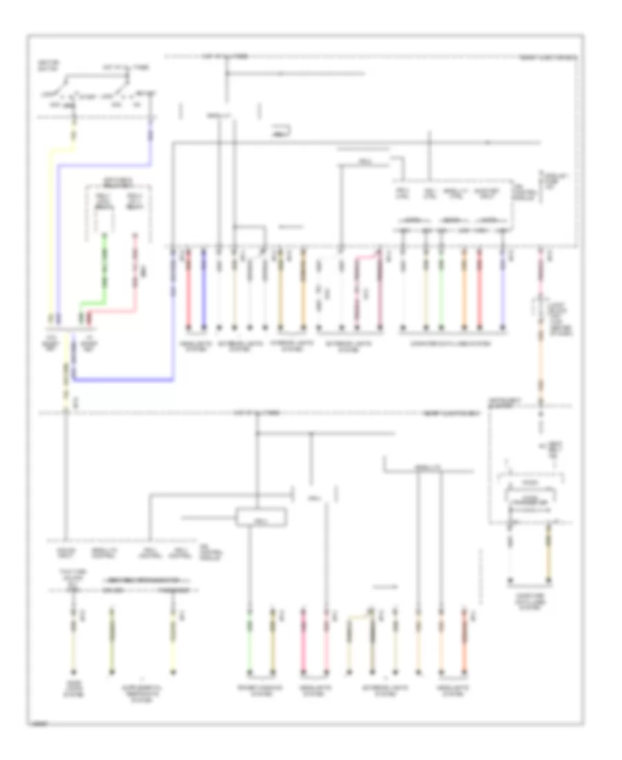
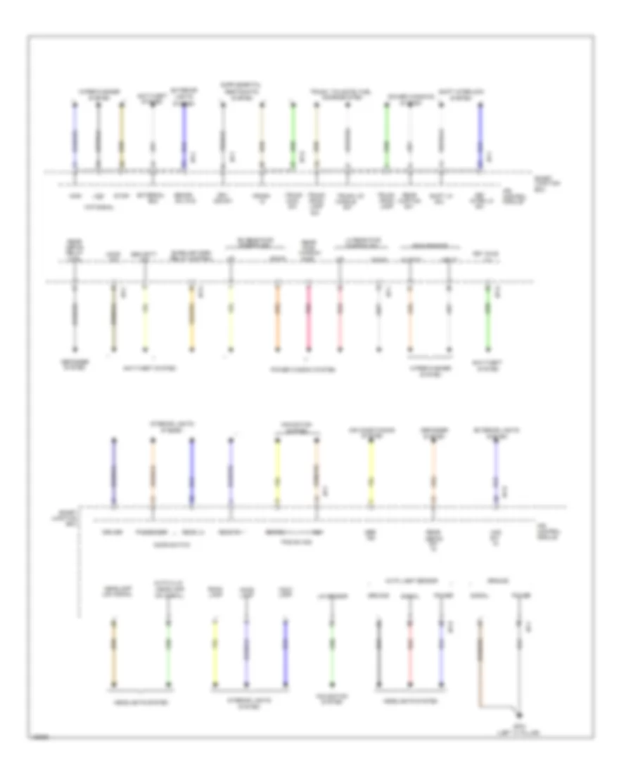
HEADLIGHTS
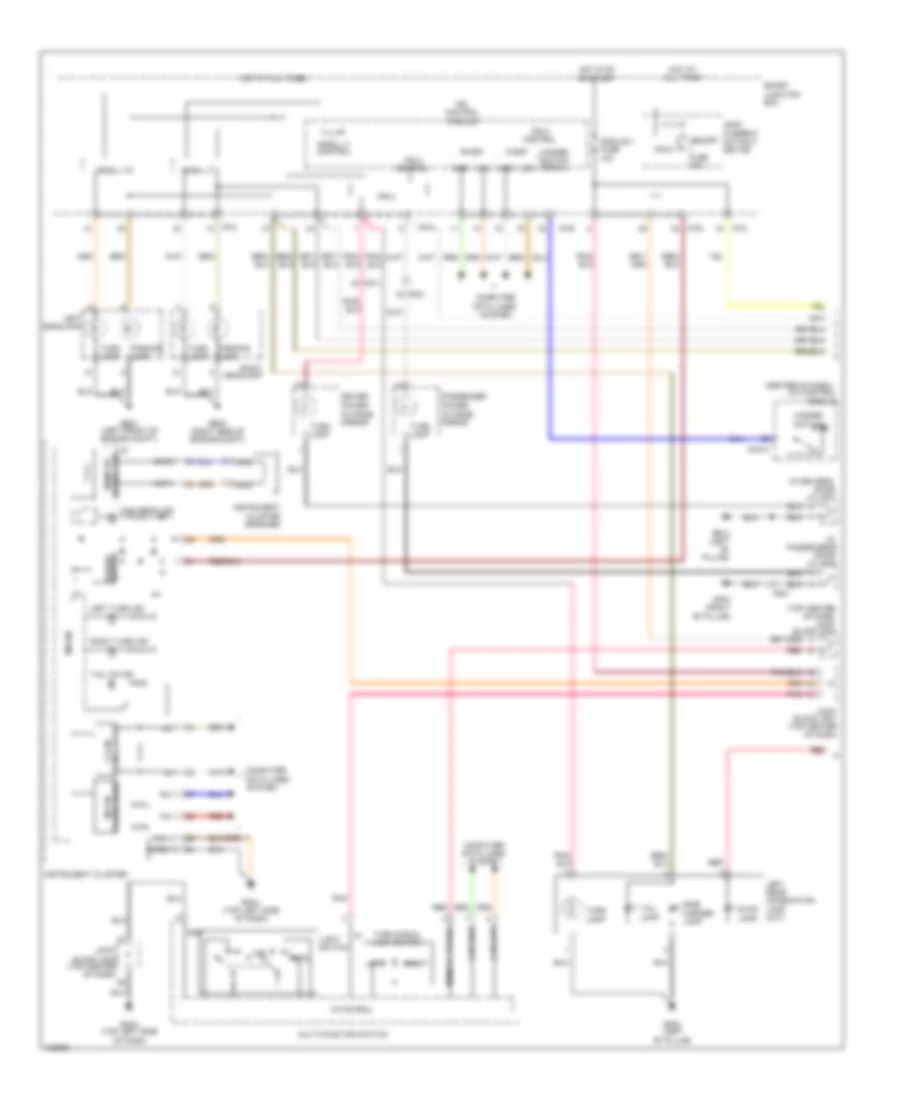
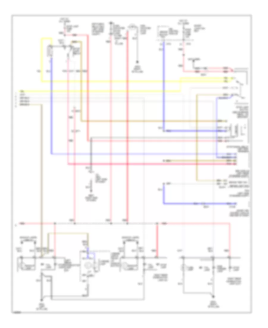
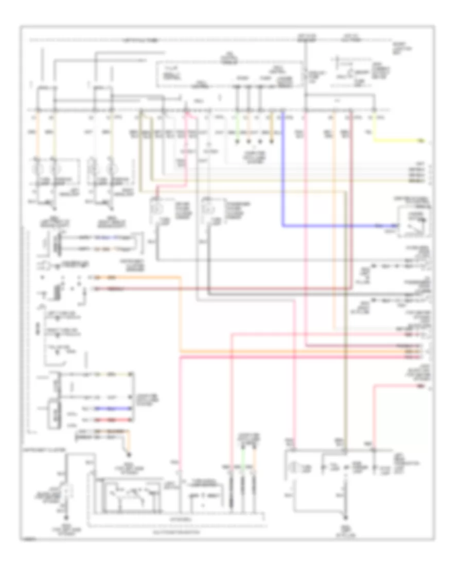
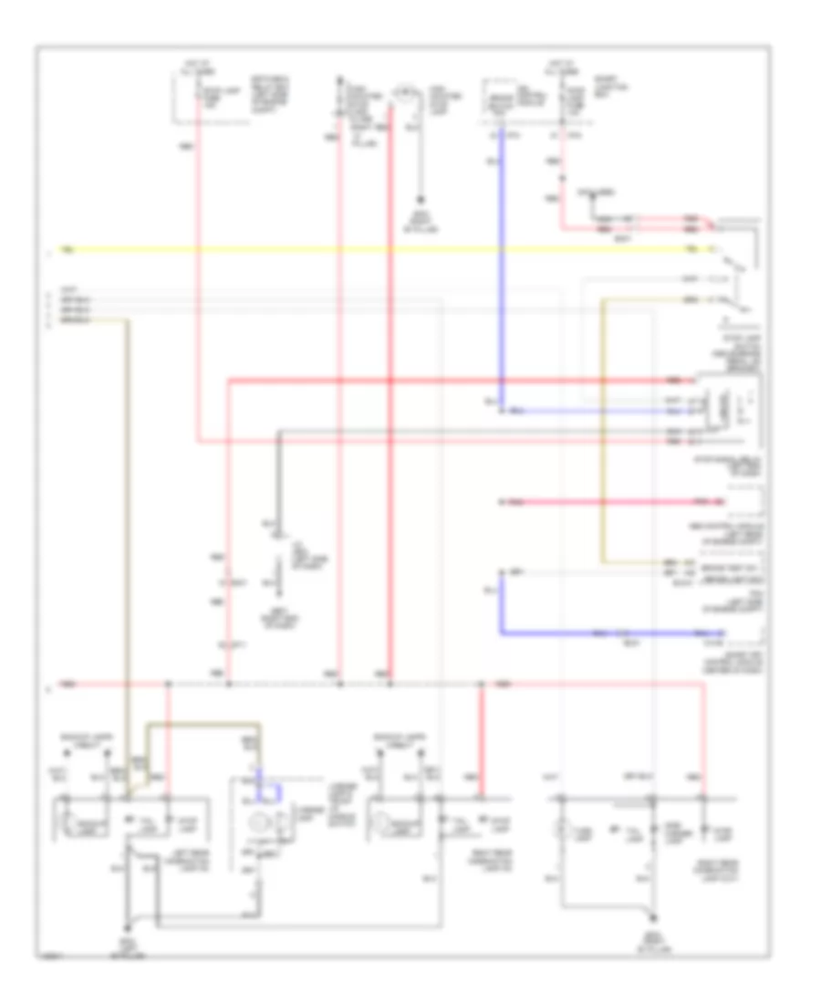
Headlamps Wiring Diagram for Hyundai Azera 2014
List of elements for Headlamps Wiring Diagram for Hyundai Azera 2014:
- (right side of engine compt)
- (top center of dash) joint block jm02
- Arisu lt ctrl
- Arisu lt1
- Arisu lt2
- Auto
- Autolight & photo sensor (if equipped) (top center of dash)
- Autolight sensor
- B-can
- C-can
- Can-high
- Can-low
- Computer data lines
- Computer data lines system
- Dim
- Dimmer/ passing switch
- Fog lamp switch
- Front fog ind
- Ge01 (left front of engine compt)
- Ge02
- Ge02 (right side of engine compt)
- Gm04 (top left side of dash)
- Gnd
- Head lamp lo sig
- High
- High beam ind
- Hot at all times
- Hot in on or start
- I/p-c
- I/p-d
- I/p-e
- Instrument cluster
- Ips 4
- Ips 4 control
- Ips 5
- Ips 5 control
- Ips control module
- Joint block jm01 (top center of dash)
- Joint block jm03 (top center of dash)
- Leak current autocut device
- Left front fog lamp
- Left headlamp
- Light switch
- Low
- M/f sw ecu
- Memory fuse 10a
- Memory power
- Micom
- Module fuse 10a
- Multi-function switch
- Off
- On/ start input
- Pass
- Pnk
- Power distribution system
- Pwr
- Red
- Right front fog lamp
- Right headlamp
- Sig
- Smart junction box
- System
- Transceiver c-can
- Transceiver m-can
Headlamps Leveling Wiring Diagram for Hyundai Azera 2014
List of elements for Headlamps Leveling Wiring Diagram for Hyundai Azera 2014:
- Actuator output
- Auto headlamp leveling device module (right rear wheelwell)
- Auto hlld (head lamp on signal)
- B-can
- Body k-line
- Computer data lines system
- Cruise control system
- Em21
- Em31
- Gm04 (top left side of dash)
- Ground
- Headlamp low on signal
- High
- Hot in on or start
- I/p-d
- I/p-e
- Ips control module
- Joint block jm01 (top center of dash)
- Joint block jm03 (top center of dash)
- Left headlamp leveling device actuator (behind left headlamp assembly)
- Low
- Mf21
- Module 1 fuse 10a
- On/start input
- Pnk
- Power distribution system
- Right headlamp leveling device actuator (behind right headlamp assembly)
- Smart junction box
- Vehicle speed input
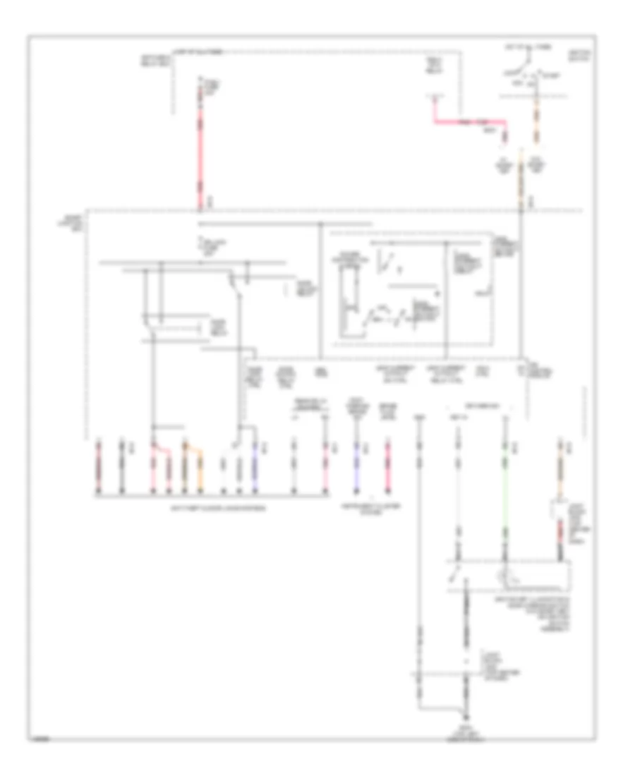
HORN
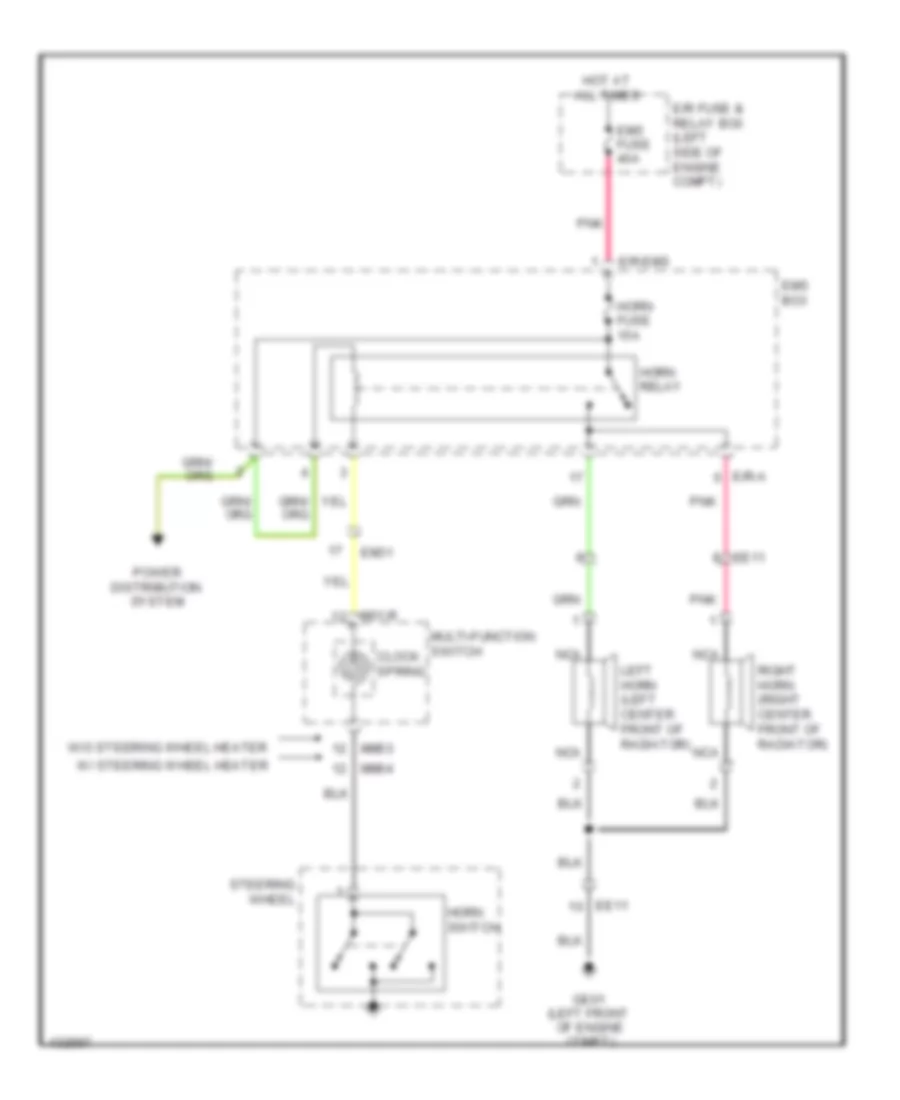
Horn Wiring Diagram for Hyundai Azera 2014
List of elements for Horn Wiring Diagram for Hyundai Azera 2014:
- Clock spring
- E/r fuse & relay box (left side of engine compt)
- E/r-a
- E/r-ems
- Ee11
- Em31
- Ems box
- Ems fuse 40a
- Ge01 (left front of engine compt)
- Horn fuse 15a
- Horn relay
- Horn switch
- Hot at all times
- Left horn (left center front of radiator)
- M01-r
- Mm03
- Mm04
- Multi-function switch
- Nca
- Pnk
- Power distribution system
- Right horn (right center front of radiator)
- Steering wheel
- W/ steering wheel heater
- W/o steering wheel heater
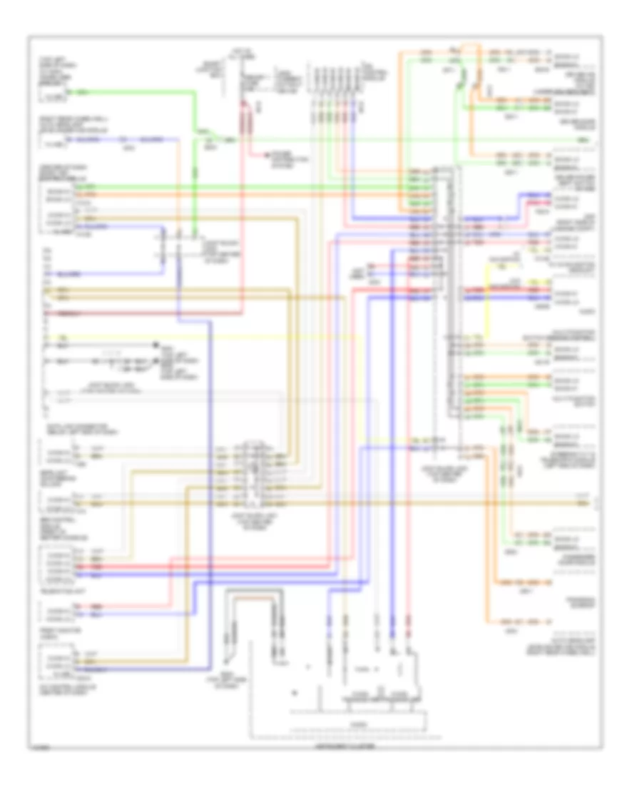
INSTRUMENT CLUSTER
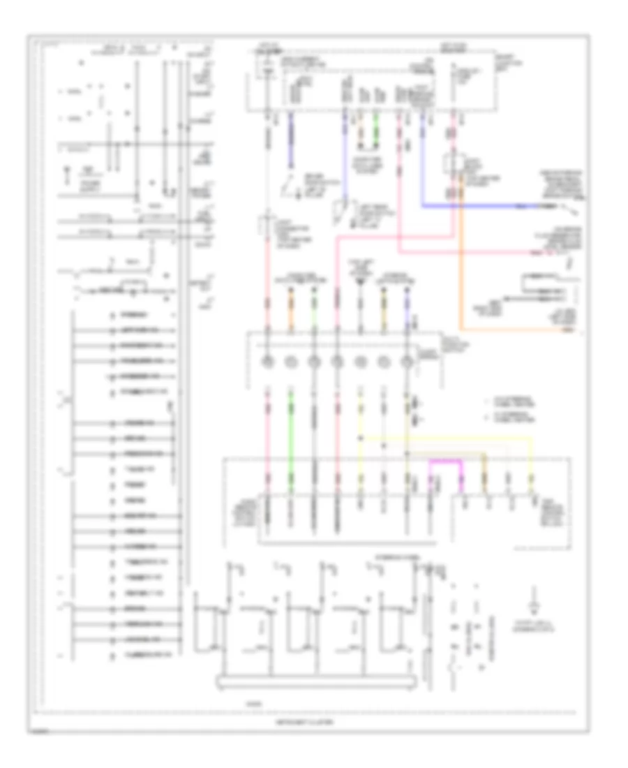
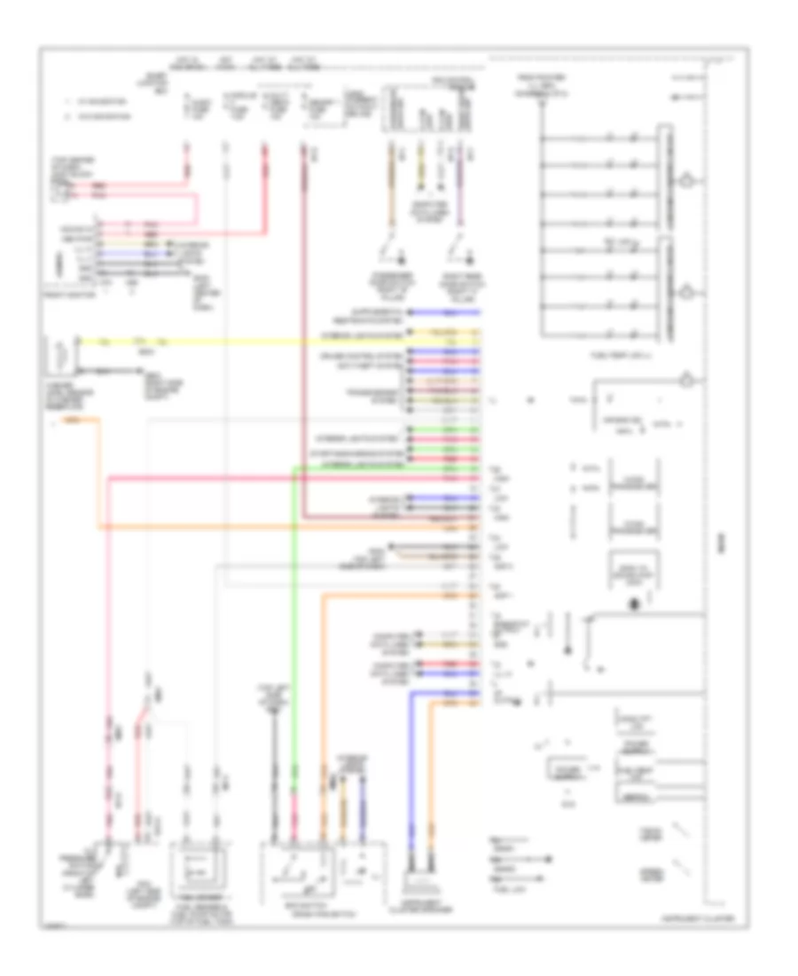
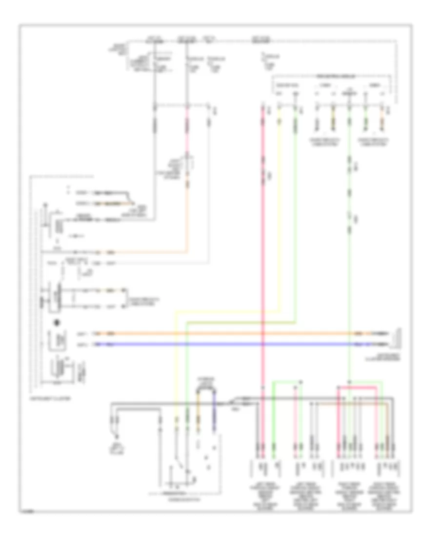
Instrument Cluster Wiring Diagram (1 of 2) for Hyundai Azera 2014
List of elements for Instrument Cluster Wiring Diagram (1 of 2) for Hyundai Azera 2014:
- (above parking brake pedal, on bracket) foot parking brake switch
- (diagram 2 of 2)
- (left "b" pillar)
- (left "c" pillar)
- (on brake fluid reservoir) brake fluid level sensor
- (top left side of dash) gm01
- 5vg
- Abs ind
- Audio remote control switch (lh high)
- B-can high
- B-can low
- Break ind
- Charge
- Charge ind
- Clock spring
- Computer data lines system
- Cruise ind
- D out
- Detent out
- Dial ill (6ea)
- Door open ind
- Door sw driver
- Down
- Driver door switch
- Eco
- Eco ind
- Ecs ind
- Ecs off ind
- Em31
- Engine check ind
- Eps ind
- Foot parking brake switch
- Front fog ind
- Fuel input
- Ge07 (right end of dash)
- Gnd
- High b-can
- High beam ind
- Hot at all times
- Hot in on or start
- I/p-c
- I/p-d
- I/p-e
- I/p-f
- Ill (+)
- Ill (-)
- Immo
- Immo ind
- Input
- Instrument cluster
- Interior lights system
- Ips 5 ctrl
- Ips control module
- Ips5
- J/c je03 (left side of dash)
- Joint block jm01 (top center of dash)
- Joint connector jm02 (top center of dash)
- Leak current autocut device
- Left rear door sw
- Left rear door switch
- Left turn ind
- Level fluid brake
- Low b-can
- Low fuel ind
- M01-r
- M102-1
- M102-2
- Mem pwr
- Memory power
- Micom
- Mm03
- Mm04
- Module 1 fuse 10a
- Multi- function switch
- N out
- Nca
- Oil pre- ssure
- Oil pressure ind
- On input
- On/ start input
- On/start in
- P out
- Pnk
- Pointer ill (4ea)
- Power
- R out
- Red
- Right right ind
- S out
- Seat belt ind
- Set ind
- Sig 3
- Smart junction box
- Steering wheel
- Tail on ind
- Temp high ind
- To tft lcd ill
- Tpms tread ind
- Trip remote control switch (rh low)
- Trunk open ind
- W/ steering wheel heater
- W/o steering wheel heater
- Washer
Instrument Cluster Wiring Diagram (2 of 2) for Hyundai Azera 2014
List of elements for Instrument Cluster Wiring Diagram (2 of 2) for Hyundai Azera 2014:
- (diagram 1 of 2)
- (top center of dash) joint block jm02
- (top left side of dash) gm01
- 4p output
- 5vg
- 80hm 1w sound chip (4ch)
- Acc/on in
- Air bag ind
- Amp 1
- Amp 2
- Anti-theft system
- Audio fuse 10a
- C-can high
- C-can low
- C-can transceiver
- Clock
- Computer
- Computer data lines system
- Constant current circuit
- Crash pad switch
- Cruise control system
- Data lines
- Ec21
- Eco switch
- Eeprom
- Elg-a
- Em21
- Em31
- From pointer
- Front monitor
- Fuel low
- Fuel sender
- Fuel sender & fuel pump motor (top of fuel tank)
- Fuel/temp lcd
- Fuel/temp lcd ill
- Ge02 (right side of engine compt)
- Gm03 (left center of dash)
- Gm04 (top left side of dash)
- Gnd
- High
- Hot at all times
- Hot in acc or on
- Hot in on
- I/p-d
- I/p-e
- I/p-f
- Ill
- Ill (+)
- Ill (-)
- Ill (4ea)
- Ind
- Instrument cluster
- Instrument cluster speaker
- Interior
- Interior lights system
- Ips control module
- Leak current autocut device
- Lights
- Low
- M-can transceiver
- M69
- M70
- Mem pwr
- Memory 1 fuse 10a
- Mf11
- Micom
- Mm02
- Module fuse 7.5a
- Mono tft lcd
- Multi media fuse 10a
- Nca
- Oil pressure switch (front of left cylinder bank)
- Passenger door sw
- Passenger door switch (right "b" pillar)
- Pcm (left side of engine compt)
- Pnk
- Red
- Restraints system
- Rheostat output
- Right rear door sw
- Right rear door switch (right "c" pillar)
- Sgnd1
- Sgnd2
- Smart junction box
- Speed- meter
- Starting/charging system
- System
- Tacho- meter
- Tft lcd ill
- Transmissions
- W/ navigation
- W/o navigation
- Washer level sensor (in washer reservoir)
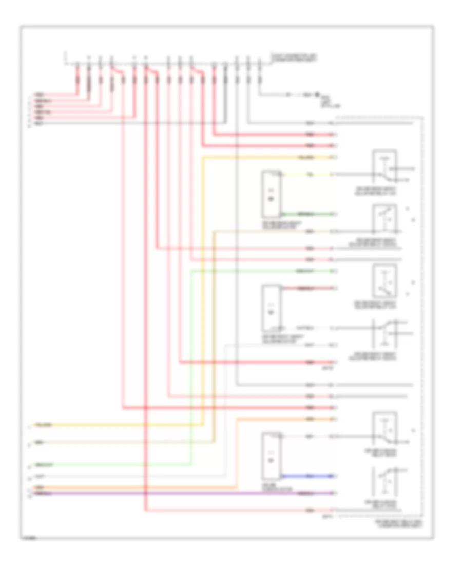
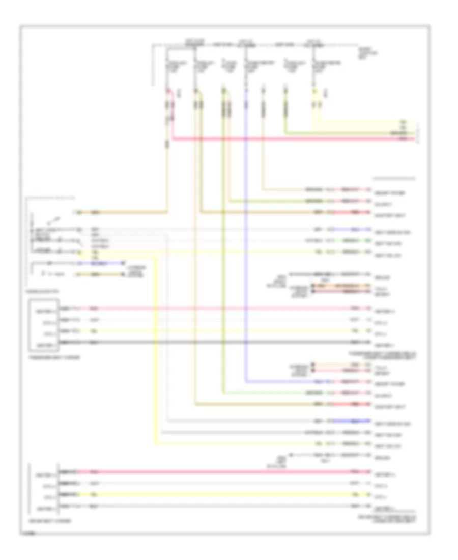
INTERIOR LIGHTS
Courtesy Lamps Wiring Diagram, with Panoramic Sunroof (1 of 2) for Hyundai Azera 2014
List of elements for Courtesy Lamps Wiring Diagram, with Panoramic Sunroof (1 of 2) for Hyundai Azera 2014:
- (not used)
- Audio fuse 10a
- C-can hi
- C-can lo
- C-can transceiver
- Computer
- Computer data lines system
- Data lines
- Door (-)
- Door lamp switch
- Door open
- Door sw driver
- Door sw left rear
- Driver foot lamp
- Foot lamp
- Gf02 (left "b" pillar)
- Gm01 (top left side of dash)
- Gm04 (top left side of dash)
- Gnd
- High
- Hot at all times
- Hot in acc or on
- Hot in on or start
- I/p-a
- I/p-d
- I/p-e
- I/p-f
- Ind
- Input
- Instrument cluster
- Interior lamp fuse 10a
- Ips control module
- J/c jm04 (top right side of dash)
- J/c jr02 (center front of roof)
- Joint block jm01 (top center of dash)
- Leak current autocut device
- Led driver
- Led socket
- Left garnish lamp
- Left led socket
- Left map lamp sw
- Left rear personal lamp
- Left vanity lamp
- Left vanity lamp switch (part of left visor hinge assembly)
- Low
- M-can transceiver
- Map lamp
- Map lamp sw
- Memory
- Memory 1 fuse 10a
- Micom
- Mm01
- Mm02
- Module 1 fuse 10a
- Mood (+)
- Mood lamp
- Motor
- Mr11
- Nca
- On/start
- Open
- Passenger door sw
- Passenger foot lamp
- Pnk
- Ptc
- Pwr
- Red
- Right garnish lamp
- Right led socket
- Right map lamp sw
- Right rear door sw
- Right rear personal lamp
- Right vanity lamp
- Right vanity lamp switch (part of right visor hinge assembly)
- Room door
- Room lamp
- Room lamp switch
- S gnd 1
- S gnd 2
- Smart junction box
- System
- Trunk
- Trunk lid motor (center rear of luggage compt lid)
- Trunk room lamp
- Trunk room lamp sw
- Trunk room lamp switch
- Trunk, tailgate, fuel doors system
Courtesy Lamps Wiring Diagram, with Panoramic Sunroof (2 of 2) for Hyundai Azera 2014
List of elements for Courtesy Lamps Wiring Diagram, with Panoramic Sunroof (2 of 2) for Hyundai Azera 2014:
- (not used)
- Dd11
- Dd21
- Dd31
- Dd41
- Driver door lamp
- Driver door mood lamp
- Driver door scuff lamp
- Driver door switch (left "b" pillar)
- Fd11
- Fd21
- Fd31
- Fd41
- Ff01
- J/c jf01 (left "c" pillar)
- J/c jf04 (right "c" pillar)
- Left rear door lamp
- Left rear door mood lamp
- Left rear door scuff lamp
- Left rear door switch (left "c" pillar)
- Mf11
- Mf21
- Nca
- Passenger door lamp
- Passenger door mood lamp
- Passenger door scuff lamp
- Passenger door switch (right "b" pillar)
- Pnk
- Right rear door lamp
- Right rear door mood lamp
- Right rear door scuff lamp
- Right rear door switch (right "c" pillar)
- Trunk room lamp
Courtesy Lamps Wiring Diagram, without Panoramic Sunroof (1 of 2) for Hyundai Azera 2014
List of elements for Courtesy Lamps Wiring Diagram, without Panoramic Sunroof (1 of 2) for Hyundai Azera 2014:
- (not used)
- Audio fuse 10a
- C-can hi
- C-can lo
- C-can transceiver
- Computer
- Computer data lines system
- Data lines
- Door (-)
- Door lamp switch
- Door open
- Door sw driver
- Door sw left rear
- Driver foot lamp
- Foot lamp
- Gf02 (left "b" pillar)
- Gm01 (top left side of dash)
- Gm04 (top left side of dash)
- Gnd
- High
- Hot at all times
- Hot in acc or on
- Hot in on or start
- I/p-a
- I/p-d
- I/p-e
- I/p-f
- Ind
- Input
- Instrument cluster
- Interior lamp fuse 10a
- Ips control module
- J/c jm04 (top right side of dash)
- J/c jr02 (center front of roof)
- Joint block jm01 (top center of dash)
- Lamp
- Leak current autocut device
- Led
- Led driver
- Left garnish lamp
- Left led socket
- Left map lamp sw
- Left vanity lamp
- Left vanity lamp switch (part of left visor hinge assembly)
- Low
- M-can transceiver
- Map
- Map lamp
- Memory
- Memory 1 fuse 10a
- Micom
- Mm01
- Mm02
- Module 1 fuse 10a
- Mood (+)
- Mood lamp
- Motor
- Mr11
- Nca
- On/start
- Open
- Passenger door sw
- Passenger foot lamp
- Pnk
- Ptc
- Pwr
- Rear personal lamp center
- Red
- Right
- Right garnish lamp
- Right led socket
- Right map lamp sw
- Right rear door sw
- Right vanity lamp
- Right vanity lamp switch (part of right visor hinge assembly)
- Room door
- Room lamp
- Room lamp switch
- S gnd 1
- S gnd 2
- Smart junction box
- Socket
- System
- Trunk
- Trunk lid motor (center rear of of luggage compt lid)
- Trunk room lamp
- Trunk room lamp sw
- Trunk room lamp switch
- Trunk, tailgate, fuel doors system
Courtesy Lamps Wiring Diagram, without Panoramic Sunroof (2 of 2) for Hyundai Azera 2014
List of elements for Courtesy Lamps Wiring Diagram, without Panoramic Sunroof (2 of 2) for Hyundai Azera 2014:
- (not used)
- Dd11
- Dd21
- Dd31
- Dd41
- Driver door lamp
- Driver door mood lamp
- Driver door scuff lamp
- Driver door switch (left "b" pillar)
- Fd11
- Fd21
- Fd31
- Fd41
- Ff01
- J/c jf01 (left "c" pillar)
- J/c jf04 (right "c" pillar)
- Left rear door lamp
- Left rear door mood lamp
- Left rear door scuff lamp
- Left rear door switch (left "c" pillar)
- Mf11
- Mf21
- Nca
- Passenger door lamp
- Passenger door mood lamp
- Passenger door scuff lamp
- Passenger door switch (right "b" pillar)
- Pnk
- Right rear door lamp
- Right rear door mood lamp
- Right rear door scuff lamp
- Right rear door switch (right "c" pillar)
- Trunk room lamp
Instrument Illumination Wiring Diagram (1 of 2) for Hyundai Azera 2014
List of elements for Instrument Illumination Wiring Diagram (1 of 2) for Hyundai Azera 2014:
- (under driver's seat)
- (under passenger's seat)
- Atm lever indicator
- Auto
- B-can
- C-can
- Can hi
- Can lo
- Computer data lines system
- Crash pad switch
- Detent out
- Device
- Down
- Driver ccs control module
- Driver seat warmer module
- Electro chromic mirror
- Fs11
- Fs21
- Gm01 (top left side of dash)
- Gnd
- High
- Hot at all times
- Hot in on or start
- I/p-a
- I/p-d
- I/p-e
- Ill (+)
- Instrument cluster
- Ips 1
- Ips 1 control
- Ips 5
- Ips 5 control
- Ips control module
- J/c jr02 (center front of roof)
- Joint block jm02 (top center of dash)
- Leak current autocut
- Light switch
- Low
- M/f sw ecu
- Memory 1 fuse 10a
- Memory pwr
- Mf11
- Micom
- Mm02
- Module 1 fuse 10a
- Mr11
- Multi-function switch
- Off
- On/start input
- Passenger ccs control module
- Passenger seat warmer module
- Pnk
- Red
- Rheostat
- Rheostat output
- S10-b
- S30-b
- Smart junction box
- Transceiver c-can
- W/ ccs
- W/o ccs
Instrument Illumination Wiring Diagram (2 of 2) for Hyundai Azera 2014
List of elements for Instrument Illumination Wiring Diagram (2 of 2) for Hyundai Azera 2014:
- (left "b" pillar) gf02
- (right "b" pillar) gf03
- (right "c" pillar) j/c jf08
- (w/ smart key) start stop button switch
- A/c control module (center of dash)
- A/v & navigation head unit
- Atm lever indicator
- Audio
- Aux & usb jack
- Console box lamp
- Console switch
- Dd11
- Dd21
- Dd31
- Dd41
- Driver ccs control module (under s10-a driver's seat)
- Driver power seat switch
- Driver seat warmer module (under driver's seat)
- Fd11
- Fd21
- Fd31
- Fd41
- Fe01
- Front monitor
- Front tray lamp
- Fs11
- Fs21
- Fuel filler door & trunk lid switch
- Gf02 (base of left "b" pillar)
- Glove box lamp
- Glove box lamp switch
- Gm01 (top left side of dash)
- Gm03 (left center of dash)
- Gm04 (top left side of dash)
- J/c jf07 (left "c" pillar)
- Joint block jm01 (top center of dash)
- Joint block jm03 (top center of dash)
- Left rear power window switch (w/ seat warmer)
- M01-r
- M03-a
- M09-a
- M14-a
- Mf21
- Mm01
- Mm02
- Multi- function switch (remote control)
- Passenger ccs control module (under s30-a passenger's seat)
- Passenger power seat switch
- Passenger seat warmer module (under passenger's seat)
- Pnk
- Red
- Right rear power window switch (w/ seat warmer)
- S10-b
- S30-b
- Ssb ill power
- Start stop button switch
- W/ ccs
- W/ memory
- W/ navigation
- W/0 navigation
- W/o ccs
- W/o memory
- W/o navigation
MEMORY SYSTEMS
Driver"s Memory Seat Wiring Diagram (1 of 2) for Hyundai Azera 2014
List of elements for Driver"s Memory Seat Wiring Diagram (1 of 2) for Hyundai Azera 2014:
- B-can
- B-can high
- B-can low
- Computer data lines system
- Down
- Driver cushion motor
- Driver ims module (under driver's seat)
- Driver lumbar support limit switch
- Driver lumbar support motor
- Drv p/seat fuse 30a
- E/r fuse & relay box (left side of engine compt)
- Ef01
- Front
- Fs11
- Gf02 (left "b" pillar)
- Gf04 (left "c" pillar)
- Gnd
- Ground
- High
- Hot at all times
- Hot in on or start
- I/p-a
- I/p-e
- Ips 5
- Ips 5 control
- Ips control module
- J/c js01 (under driver's seat)
- Leak current autocut device
- Low
- Memory power
- Module 2 fuse 7.5a
- Off
- On/start input
- Pnk
- Power distribution system
- Rear
- Red
- S04-a
- S04-b
- S04-c
- S04-d
- Sensor power
- Smart junction box
- Ss01
Driver"s Memory Seat Wiring Diagram (2 of 2) for Hyundai Azera 2014
List of elements for Driver"s Memory Seat Wiring Diagram (2 of 2) for Hyundai Azera 2014:
- (not used)
- B-can high
- B-can low
- Computer data lines system
- Dd11
- Dr slide sw bwd
- Dr slide sw fwd
- Driver front height adjuster motor
- Driver power seat switch
- Driver rear height adjuster motor
- Driver reclining motor
- Driver slide motor
- Fd11
- Gf02 (left "b" pillar)
- Ground
- Hot at all times
- Hot in on or start
- I/p-a
- Ill (+)
- Ill (-)
- Interior lights system
- J/c jd01 (in driver's door)
- J/c js01 (under driver's seat)
- Leak current autocut device
- Memory 1 fuse 10a
- Memory power
- Module 1 fuse 10a
- Nca
- On/start input
- Pnk
- Red
- Smart junction box
- Ss01
Memory Mirrors Wiring Diagram (1 of 2) for Hyundai Azera 2014
List of elements for Memory Mirrors Wiring Diagram (1 of 2) for Hyundai Azera 2014:
- (+)
- (-)
- (not used)
- +5v
- +5va
- +5vb
- +vbat
- +vp
- B-can
- Can transceiver ic
- Computer data lines system
- Dd11
- Defogger
- Defogger system
- Driver door module
- Driver power outside mirror
- Ec mirror
- Exterior lights system
- Fd11
- Fold
- Gf02 (left "b" pillar)
- Gnd
- Ground distribution system
- High
- Hor
- Hot at all times
- Hot in on or start
- I/p-a
- I/p-e
- Input circuit
- Ips control module
- J/c jd01 (in driver's door)
- Leak current autocut device
- Lh/rh
- Low
- Mcu
- Memory 1 fuse 10a
- Memory power
- Mirr down
- Mirr left
- Mirr right
- Mirr select l
- Mirr select r
- Mirr up
- Mirror b+
- Mirror control ic
- Mirrors system
- Module 1 fuse 10a
- Nca
- On/start input
- Outside mirror
- P gnd
- Pwr
- Regulator ic
- S gnd
- Smart junction box
- Snsr gnd
- Snsr h
- Snsr pwr
- Snsr v
- Turn lamp
- Unfold
- Up/down
- Ver
Memory Mirrors Wiring Diagram (2 of 2) for Hyundai Azera 2014
List of elements for Memory Mirrors Wiring Diagram (2 of 2) for Hyundai Azera 2014:
- (+)
- (-)
- (not used)
- +5v
- +5vb
- +vbat
- +vp
- B-can high
- B-can low
- Can transceiver ic
- Computer data lines system
- Dd11
- Dd21
- Defogger
- Defogger system
- Dr slide sw bwd
- Dr slide sw fwd
- Driver power seat switch
- Ec mirror
- Exterior lights system
- Fd11
- Fd21
- Fold
- Gf02 (left "b" pillar)
- Gf03 (right "b" pillar)
- Gnd
- Ground
- Ground distribution system
- High
- Hor
- Hot at all times
- Hot in on or start
- I/p-a
- Ill (+)
- Ill (-)
- Input circuit
- Interior lights system
- J/c jd01 (in driver's door)
- J/c jd02 (in passenger's door)
- Leak current autocut device
- Lh/rh
- Low
- Mcu
- Memory 1 fuse 10a
- Memory power
- Mirror b+
- Mirror control ic
- Mirrors system
- Module 1 fuse 10a
- Nca
- On/start input
- Outside mirror
- P gnd
- Passenger door module
- Passenger power outside mirror
- Pnk
- Pwr
- Red
- Regulator ic
- S gnd
- Smart junction box
- Snsr gnd
- Snsr h
- Snsr pwr
- Snsr v
- Turn lamp
- Unfold
- Up/down
- Ver
Memory Power Tilt & Power Telescopic Wiring Diagram (1 of 2) for Hyundai Azera 2014
List of elements for Memory Power Tilt & Power Telescopic Wiring Diagram (1 of 2) for Hyundai Azera 2014:
- +5v
- +5va
- +vbat
- B-can ic
- Bwd
- Computer data lines system
- Down
- Fwd
- Gm01 (top left side of dash)
- Gm04 (top left side of dash)
- Gnd
- Ground
- High
- Hot at all times
- Hot in on or start
- I/p-d
- Ips 5
- Ips 5 control
- Ips control module
- Joint block jm01 (top center of dash)
- Joint block jm02 (top center of dash)
- Joint block jm03 (top center of dash)
- Leak current autocut device
- Low
- Mcu
- Memory power
- Module 1 fuse 10a
- On/start input
- P/handle fuse 15a
- Pnk
- Red
- Sig
- Smart junction box
- Steering tilt & telescopic module (left end of dash)
- Vcc
Memory Power Tilt & Power Telescopic Wiring Diagram (2 of 2) for Hyundai Azera 2014
List of elements for Memory Power Tilt & Power Telescopic Wiring Diagram (2 of 2) for Hyundai Azera 2014:
- (not used)
- B-can high
- B-can low
- Computer data lines system
- Dd11
- Dr slide sw bwd
- Dr slide sw fwd
- Driver power seat switch
- Fd11
- Gf02 (left "b" pillar)
- Gnd
- Ground
- Hot at all times
- Hot in on or start
- I/p-a
- Ill (+)
- Ill (-)
- Interior lights system
- J/c jd01 (in driver's door)
- Leak current autocut device
- Memory 1 fuse 10a
- Memory power
- Module 1 fuse 10a
- Motor
- Nca
- On/start input
- Pnk
- Red
- Sig
- Smart junction box
- Steering telescopic motor (on steering column)
- Steering tilt & telescopic switch
- Steering tilt motor (on steering column)
- Tele in
- Tele out
- Tilt down
- Tilt up
- Vcc
NAVIGATION
Mobile Telematic System Wiring Diagram for Hyundai Azera 2014
List of elements for Mobile Telematic System Wiring Diagram for Hyundai Azera 2014:
- A/bag
- Acc/on in
- Am/
- Am/fm
- Audio (+)
- Audio (-)
- Audio (w/o navigation) a/v & navigation head unit (w/ navigation)
- Audio fuse 10a
- Audio out (+)
- Audio out (-)
- C-can hi
- C-can lo
- Cdma
- Circuit
- Circuit power
- Computer data lines system
- Crash
- Crash input
- Electrochromic mirror
- Fm2
- Gm03 (left center of dash)
- Gm03 (left center side of dash)
- Gnd
- Gps
- Hot at all times
- Hot in acc or on
- Hot in on or start
- I/p-d
- I/p-e
- Ips control module
- Joint block jm01 (top center of dash)
- Joint block jm02 (top center of dash)
- Keypad gnd
- Keypad sig
- Leak current autocut device
- Left glass antenna amp
- M-can hi
- M-can lo
- M09-b
- M09-b m14-b
- M10
- M14-a m09-a
- M14-c
- M78
- M78-g
- Matching
- Mem power
- Mf21
- Mic (+)
- Mic (-)
- Mic in (+)
- Mic in (-)
- Mic out (+)
- Mic out (-)
- Mic shield
- Microphone (top of left "a" pillar)
- Mm05
- Mm06
- Module 1 fuse 10a
- Mr11
- Multi media fuse 10a
- Nca
- On/start in
- Out
- Pnk
- Red
- Remote
- Right glass antenna amp (right "c" pillar)
- Roof antenna
- Smart junction box
- Srs control module (front of center console)
- Sw1
- Sw2
- Sw3
- Telemetics unit (center of dash)
- Tmu
- W/ navigation
- W/o navigation
- Xm (sdars)
Navigation Wiring Diagram (1 of 4) for Hyundai Azera 2014
List of elements for Navigation Wiring Diagram (1 of 4) for Hyundai Azera 2014:
- A/v & navigation head unit
- Acc/on input
- Am/fm
- Aux detect
- Aux gnd
- Aux l in
- Aux r in
- Aux video
- Aux video gnd
- Backup sig
- Circuit
- Computer data lines system
- Cruise control system
- Ff11
- Fm2
- Gm03 (left center of dash)
- Gnd
- Gps
- Ill (+)
- Ill (-)
- Interior lights system
- Interior lights system exterior lights system
- Left glass antenna amp
- License lamp & trunk lid handle switch (w/ rear camera)
- M-can hi
- M-can low
- M14-a
- M14-b
- Memory power
- Mf21
- Mic (+)
- Mic (-)
- Microphone (top of left "a" pillar)
- Mm05
- Mm06
- Mr11
- Navi voice (+)
- Navi voice (-)
- Navigation system
- Nca
- Pnk
- Power
- Pwr
- Rear camera
- Red
- Remote antenna
- Right glass antenna amp (right "c" pillar)
- Roof antenna
- Shield gnd
- Spdif (+)
- Spdif (-)
- Spdif gnd
- V gnd
- V video
- V-gnd
- V-out
- Vehicle speed sig
- W/ tmu
- W/o tmu
- Xm (sdars)
Navigation Wiring Diagram (2 of 4) for Hyundai Azera 2014
List of elements for Navigation Wiring Diagram (2 of 4) for Hyundai Azera 2014:
- (+)
- (-)
- (left center of dash) gm03
- (usb high speed cable)
- A/v & navigation head unit
- Acc/on input
- Audio in (+)
- Audio in (-)
- Audio out
- Aux & usb jack
- Aux det
- Aux gnd
- Aux l out
- Aux r out
- Aux video
- Aux video gnd
- Bl on
- Front monitor
- Gm03 (left center of dash)
- Gnd
- Ill (+)
- Ill (-)
- Interior lights system
- Lvds (+)
- Lvds (-)
- Lvds lock
- Lvds pdn
- M14-c
- M14-g
- M14-lvds
- M14-usb
- M70
- M70-g
- M70-lvds
- M90
- M90-usb
- Memory power
- Mm01
- Nca
- Pnk
- Red
- Rs485 rx (+)
- Rs485 rx (-)
- Rs485 tx (+)
- Rs485 tx (-)
- Telemetics unit (w/ tmu) (center of dash)
- Usb d (+)
- Usb d (-)
- Usb gnd
- Usb vcc
Navigation Wiring Diagram (3 of 4) for Hyundai Azera 2014
List of elements for Navigation Wiring Diagram (3 of 4) for Hyundai Azera 2014:
- Audio fuse 10a
- B-can
- Call
- Can high
- Can low
- Clock spring
- End of call
- Gm01 (top left side of dash)
- Gnd
- Hot at all times
- Hot in acc or on
- Hot in on or start
- I/p-a
- I/p-d
- I/p-e
- Ill (+)
- Ill (-)
- Interior lights system
- Ips 5
- Ips 5 control
- Ips control module
- Joint block jm01 (top center of dash) pnk/
- Joint block jm02 (top center of dash)
- Leak current autocut device
- Left high audio remote control switch
- M01-r
- M102-1
- M102-2
- Memy pwr
- Micom
- Mm03
- Mm04
- Mode
- Module fuse 10a
- Multi media fuse 10a
- Multi-function switch
- Mute
- On/st input
- Pnk
- Red
- Seek (+)
- Seek (-)
- Sig 1
- Smart junction box
- Steering wheel
- Voice
- Volume (+)
- Volume (-)
- W/ steering wheel heater
- W/o steering wheel heater
Navigation Wiring Diagram (4 of 4) for Hyundai Azera 2014
List of elements for Navigation Wiring Diagram (4 of 4) for Hyundai Azera 2014:
- (+)
- (-)
- (right "c" pillar) gf05
- Acc/on input
- Amp (right side of luggage compt)
- Amp fuse 25a
- Center (+)
- Center (-)
- Center speaker
- Computer data lines system
- Dd31
- Dd41
- Dr (+)
- Dr (-)
- Driver door speaker
- Driver dr (+)
- Driver dr (-)
- F02-a
- F02-b
- F02-c
- Fd11
- Fd21
- Fd31
- Fd41
- Gnd
- Hot at all times
- I/p-a
- Left front midrange speaker
- Left rear door speaker
- Left rear tweeter speaker
- Left surround speaker
- Lh (+)
- Lh (-)
- Lh front (+)
- Lh front (-)
- Lh rear (+)
- Lh rear (-)
- M-can hi
- M-can lo
- Mem pwr
- Mf11
- Mf21
- Navi voice (+)
- Navi voice (-)
- Nca
- Passenger door speaker
- Pnk
- Red
- Rh (+)
- Rh (-)
- Rh front (+)
- Rh front (-)
- Rh rear (+)
- Rh rear (-)
- Right front midrange speaker
- Right rear door speaker
- Right rear tweeter speaker
- Right surround speaker
- Smart junction box
- Spdif d (+)
- Spdif d (-)
- Sub 1 (+)
- Sub 1 (-)
- Sub 2 (+)
- Sub 2 (-)
- Woofer speaker
Parking Assistant Wiring Diagram for Hyundai Azera 2014
List of elements for Parking Assistant Wiring Diagram for Hyundai Azera 2014:
- 5vg
- Amp 1
- Amp 2
- B-can
- C-can
- Chip sound
- Computer data lines system
- Console switch
- Fr01
- Gf04 (left "c" pillar)
- Gm04 (top left side of dash)
- Gnd
- Hot at all times
- Hot in on
- Hot in on or start
- I/p-a
- I/p-d
- I/p-e
- I/p-f
- Ill
- Ind
- Input
- Instrument cluster
- Instrument cluster speaker
- Interior lights system
- Ips control module
- Joint block jm01 (top center of dash)
- Lcd mono tft
- Leak current autocut device
- Left rear parking assist sensor (behind left end of rear bumper)
- Left rear parking assist sensor (center) (behind center left side of rear bumper)
- Lid1
- Lid2
- Lin
- Lin sensor
- Memory
- Memory fuse 10a
- Mf11
- Micom
- Module fuse 10a
- Module fuse 7.5a
- Nca
- On/st input
- Pas sw sig
- Pas switch
- Pnk
- Power
- Pwr
- Right rear parking assist sensor (behind right end of rear bumper)
- Right rear parking assist sensor (center) (behind center right side of rear bumper)
- S gnd 1
- S gnd 2
- Smart junction box
- Transceiver c-can
POWER DISTRIBUTION
Power Distribution Wiring Diagram (1 of 8) for Hyundai Azera 2014
List of elements for Power Distribution Wiring Diagram (1 of 8) for Hyundai Azera 2014:
- (ig 1)
- (ig 2)
- (left side of engine compt) e/r fuse & relay box
- (under driver's seat)
- Abs control module
- Alt fuse 180a
- Alternator
- Ams fuse 10a
- Battery
- Battery & battery fuse box
- Battery sensor
- Blower fuse 40a
- Blower relay
- Body ground
- Box (diagram 4 of 8)
- Box (diagram 7 of 8)
- Burglar horn relay
- C/fan (hi) relay
- C/fan (lo) relay
- C/fan fuse 50a red
- Deicer fuse 20a
- Deicer relay
- Diagnosis fuse 20a
- Driver ims module
- Driver lumbar support limit switch
- Driver reclining limit switch
- Driver seat relay box
- Drv p/ seat fuse 30a
- E/r fuse & relay box (left side of engine compt)
- E/r-a
- E/r-b
- E/r-ems
- Ec21
- Ecs 1 fuse 40a
- Ecu 1 fuse 30a
- Ecu 3 fuse 15a
- Ecu 4 fuse 10a
- Ecu 5 fuse 10a
- Ef01
- Elg-a
- Em31
- Ems box
- Ems fuse 40a
- Engine control relay
- Esc 2 fuse 40a
- Esc module
- F/pump fuse 20a
- F/pump relay
- From mdps fuse (diagram 1 of 8)
- From smart junction box g (diagram 2 of 8)
- Fs11
- Horn fuse 15a
- Horn relay
- Icm relay box (right end of dash)
- Idb (injector driver box)
- Ign 1 fuse 15a
- Ign 1 fuse 40a
- Ign 2 fuse 40a
- Ip b+1 fuse 40a red
- Ip b+2 fuse 60a
- Ip b+3 fuse 60a
- Ip b+4 fuse 60a
- J/c js01 (under driver's seat)
- Junction
- Junction box (diagram 4 of 8)
- Key
- Lamp fuse (diagram 1 of 8)
- Mdps fuse 80a
- Mdps unit
- Multi fuse
- Multipurpose check connector
- Outlet relay (diagram 8 of 8)
- Pcm
- Pnk
- Power outlet fuse 25a
- Red
- Relay (diagram 8 of 8)
- Rr htd fuse 40a
- Rr htd relay
- S04-b
- S07-a
- S07-b
- S07-c
- Smart
- Start motor
- Start relay
- Stop lamp fuse 15a
- Stop lamp relay
- Stop signal relay
- Switch (diagram 2 of 8)
- To ignition
- To pdm 2
- To pdm 3
- To power
- To smart
- To stop
- Transaxle range switch
- W/ 8 way
- W/ 8 way & cushion
- W/ esc
- W/ ims
- W/ smart key
- W/o
- W/o esc
- W/o smart key
Power Distribution Wiring Diagram (2 of 8) for Hyundai Azera 2014
List of elements for Power Distribution Wiring Diagram (2 of 8) for Hyundai Azera 2014:
- (diagram 2 of 8)
- 1 fuse (diagram 3 of 8)
- A/bag fuse 15a
- A/bag ind fuse 7.5a
- A/c control module
- A/v & navigation head unit
- Abs control module
- Acc
- Acc/on input
- Active incar sensor
- Amp
- Audio
- Audio fuse 10a
- Clock spring
- Console switch
- Dd31
- Dd41
- Driver ims module
- E/r fuse & relay box (left side of engine compt)
- Em31
- Esc
- Esc module
- F02-a
- Fd31
- Fd41
- Fr01
- From a/bag
- From ign 2 fuse (diagram 1 of 8)
- From multi fuse (diagram 1 of 8)
- From pdm 1 (acc) relay (diagram 8 of 8)
- From pdm 2 (ig 1) relay (diagram 8 of 8)
- From pdm 3 (ig 2) relay (diagram 8 of 8)
- Front monitor
- Fs11
- Fuse
- Htd strg fuse 15a
- I/p-a
- I/p-c
- I/p-d
- Ign 1 fuse 20a
- Ignition switch (w/o smart key)
- Immo fuse 7.5a
- Immobilizer module
- Instrument cluster
- Ips control module
- Joint block jm02 (top center of dash)
- Key
- Left rear parking assist sensor
- Left rear parking assist sensor (center)
- Left rear power window switch (w/ seat warmer)
- Left rear seat warmer
- Lock
- M03-b
- M09-b
- M13-a
- M14-b
- M26
- M69
- M70
- M74
- Map lamp
- Mdps fuse 7.5a
- Mdps unit
- Mf11
- Mm04
- Module fuse 7.5a
- Mr11
- On input
- On/start input
- Passenger occupant detection sensor
- Pnk
- Red
- Right rear parking assist sensor
- Right rear parking assist sensor (center)
- Right rear power window switch (w/ seat warmer)
- Right rear seat warmer
- S04-d
- Smart
- Smart junction box
- Smart key control module
- Smart key control module (if equipped)
- Srs control module
- Start
- Starting/ charging system
- Steering wheel
- Steering wheel heater
- Steering wheel heater module
- Telematics unit
- To c/lighter fuse (diagram 8 of 8)
- To ecu 5 fuse (diagram 1 of 8)
- To immo fuse (diagram 2 of 8)
- To module
- To module 3 fuse (diagram 3 of 8)
- To power outlet relay (diagram 8 of 8)
- W/ esc
- W/ ims
- W/ navigation
- W/ smart key
- W/o
- W/o navigation
- W/o smart key
- Washer relay
- Wiper (hi) relay
- Wiper (lo) relay
- Wiper fuse 25a
- Wiper motor
Power Distribution Wiring Diagram (3 of 8) for Hyundai Azera 2014
List of elements for Power Distribution Wiring Diagram (3 of 8) for Hyundai Azera 2014:
- (top center of dash) joint block jm01
- A/c control module
- A/con fuse 7.5a
- Atm lever indicator
- Auto head lamp leveling device module
- Blower relay
- Cluster ionizer
- Crash pad switch
- Dd11
- Dd21
- Driver ccs control module
- Driver door module
- Driver power seat switch (w/ ims)
- Driver seat warmer module
- E/r fuse & relay box (left side of engine compt)
- Electro chromic mirror
- Em31
- En31
- Fd11
- Fd21
- Fr01
- From ip control module k (diagram 2 of 8)
- From module 2 fuse j (diagram 2 of 8)
- Fs11
- Fs21
- I/p-a
- I/p-c
- I/p-d
- Instrument cluster
- J/c jr02 (center front of roof)
- Joint block jm01 (top center of dash)
- Left head lamp leveling device actuator
- Left rear seat warmer
- M01-r
- M03-b
- M13-a
- Mf11
- Mf21
- Mm02
- Module 1 fuse 10a
- Module 3 fuse 7.5a
- Mr11
- Multi- function switch (remote control)
- Multi-function switch
- Panorama sunroof
- Passenger ccs control module
- Passenger door module
- Passenger seat warmer module
- Pnk
- Rain sensor
- Red
- Right head lamp leveling device actuator
- Right rear seat warmer
- S10-b
- S30-b
- Smart junction box
- Smart key control module (if equipped)
- Steering tilt & telescopic module
- Stop lamp relay
- Stop lamp switch
- Telematics unit
- Tire pressure monitoring module
- W/ ccs
- W/ esc
- W/o ccs
Power Distribution Wiring Diagram (4 of 8) for Hyundai Azera 2014
List of elements for Power Distribution Wiring Diagram (4 of 8) for Hyundai Azera 2014:
- (diagram 5 of 8)
- (diagram 6 of 8)
- (not used)
- (w/ smart key)
- Amp
- Amp fuse 25a
- Arisu- lt 2 ctrl
- Arisu-lt 2
- Dd31
- Dd41
- Door lock relay
- Door unlock relay
- Dr lock fuse 20a
- Driver ccs control module
- Driver ims module
- Driver safety power window module
- Driver seat warmer module
- Electro chromic mirror
- Em31
- F02-a
- Fd11
- Fd21
- Fd31
- Fd41
- From ip b+1 h fuse (diagram 1 of 8)
- From ips 3 l (diagram 4 of 8)
- From multi b fuse (diagram 1 of 8)
- From multi d fuse (diagram 1 of 8)
- Fs11
- Fs21
- Fuel filler door & trunk lid switch
- I/p-a
- I/p-b
- I/p-c
- I/p-d
- Icm relay box (right end of dash)
- Ignition key ill & door warning switch
- Immobilizer module
- Ips 3
- Ips 4
- Ips 5
- Ips 5 ctrl
- Ips control module
- Ips ctrl
- Joint block jm02 (top center of dash)
- Lamp fuse (diagram 4 of 8)
- Left front fog lamp
- Left headlamp
- Left rear combination lamp (in)
- Left rear combination lamp (out)
- Left rear power window switch (w/ seat warmer)
- Left rear seat warmer
- License lamp
- License lamp & trunk lid handle switch
- M01-r
- M13-a
- Memory power
- Mf11
- Mm02
- Mr11
- Multi- function switch
- Multi- function switch (remote control)
- Nca
- P/wdw lh fuse 25a
- P/wdw rh fuse 25a
- Passenger ccs control module
- Passenger safety power window module
- Passenger seat warmer module
- Pnk
- Rear curtain motor
- Red
- Right front fog lamp
- Right rear power window switch (w/ seat warmer)
- Right rear seat warmer
- S/heater frt fuse 20a
- S/heater rr fuse 20a
- S04-d
- S10-a
- S30-a
- Smart junction box
- Smart key 1 fuse 25a
- Smart key control module
- Steering tilt & telescopic module
- Stop lamp fuse 10a
- Stop lamp switch
- To leak current autocut relay
- To start/ stop button switch
- To stop
- Trunk fuse 10a
- Trunk lid relay
- Two turn unlock relay
- W/ ccs
- W/ ims
- W/ smart key
- W/o ccs
- W/o smart key
Power Distribution Wiring Diagram (5 of 8) for Hyundai Azera 2014
List of elements for Power Distribution Wiring Diagram (5 of 8) for Hyundai Azera 2014:
- (not used)
- Center rear personal lamp
- Dd11
- Dd21
- Dd31
- Dd41
- Driver door lamp
- Driver door mood lamp
- Driver door scuff lamp
- Driver foot lamp
- Fd11
- Fd21
- Fd31
- Fd41
- Ff01
- From dr lock w
- From interior lamp x
- Fuse (diagram 4 of 8)
- Fuse (diagram 5 of 8)
- I/p-a
- I/p-d
- Interior lamp fuse 10a
- Ips control module
- Joint block jf01 (left "c" pillar)
- Joint block jf04 (right "c" pillar)
- Joint block jm04 (top right side of dash)
- Joint block jr02 (center front of roof)
- Leak current autocut device
- Leak current autocut relay
- Leak current autocut rly control
- Leak current autocut sw control
- Leak current autocut switch
- Left garnish lamp
- Left rear door lamp
- Left rear door mood lamp
- Left rear door scuff lamp
- Left rear personal lamp
- Left vanity lamp switch
- Map lamp
- Mm01
- Mm02
- Mr11
- Nca
- Off
- Passenger door lamp
- Passenger door mood lamp
- Passenger door scuff lamp
- Passenger foot lamp
- Pnk
- Red
- Right garnish lamp
- Right rear door lamp
- Right rear door mood lamp
- Right rear door scuff lamp
- Right rear personal lamp
- Right vanity lamp switch
- Smart junction box
- To leak current autocut device (diagram 5 of 8)
- To memory 1 fuse (diagram 6 of 8)
- Trunk room lamp
- W/ panorama sunroof
- W/o panorama sunroof
Power Distribution Wiring Diagram (6 of 8) for Hyundai Azera 2014
List of elements for Power Distribution Wiring Diagram (6 of 8) for Hyundai Azera 2014:
- A/c control module
- A/v & navigation head unit
- Audio
- Auto light & photo sensor
- Data link connector
- Dd11
- Dd21
- Driver door module
- Driver power seat switch
- Fd11
- Fd21
- Fr01
- From leak current autocut y
- From smart junction box (diagram 4 of 8)
- Front monitor
- Gm04 (top left side of dash)
- Gnd
- Gnd ssb ill
- I/p-a
- I/p-d
- I/p-e
- Immo ant
- Immo ant_gnd
- Immo ant_pwr
- Instrument cluster
- Interior lights system
- Ips control module
- Joint block jm03 (top center of dash)
- Key hole ill
- Leak current autocut device
- Led-off
- Led-on
- M03-b
- M09-b
- M13-a
- M13-b
- M13-c
- M14-b
- M69
- M70
- Memory 1 fuse 10a
- Memory 2 fuse 7.5a
- Memory pwr
- Mf11
- Multi media fuse 10a
- Passenger door module
- Pwr
- Pwr ssb ill
- Red
- Rf receiver
- Rheostat
- Smart junction box
- Smart key control module
- Ssb
- Ssb ill
- Ssb ill gnd
- Ssb ill pwr
- Ssb led acc
- Ssb led off
- Ssb led on
- Ssb led-acc
- Ssb sw 1
- Ssb sw 2
- Ssb sw1
- Ssb sw2
- Start stop button switch (w/ smart key)
- Switch (diagram 5 of 8)
- Telematics unit
- Tire pressure monitoring module
- W/ ims
- W/ navigation
- W/ smart key
- W/o navigation
Power Distribution Wiring Diagram (7 of 8) for Hyundai Azera 2014
List of elements for Power Distribution Wiring Diagram (7 of 8) for Hyundai Azera 2014:
- (under passenger's seat)
- 4 way passenger seat
- 8 way passenger seat
- A/c control module
- A/v & navigation head unit
- Arisu- lt 1 ctrl
- Arisu-lt 1
- Atm lever indicator
- Aux & usb jack
- Console box lamp
- Console switch
- Crash pad switch
- Dd11
- Dd21
- Dd41
- Driver ccs control module
- Driver power outside mirror
- Driver power seat switch
- Driver seat warmer module
- Fd11
- Fd21
- Fd31
- Fd41
- Ff01
- From multi c fuse (diagram 1 of 8)
- From pass p/seat fuse m (diagram 7 of 8)
- Front monitor
- Front tray lamp
- Fs11
- Fs21
- Fuel filler door & trunk lid switch
- Glove box lamp
- I/p-a
- I/p-b
- I/p-c
- I/p-d
- Instrument cluster
- Ips 1
- Ips 2
- Ips control control
- Ips control module
- Ips ctrl
- J/c jf07 (left "c" pillar)
- J/c js02 (under passenger's seat)
- Joint block jm01 (top center of dash)
- Left rear combination lamp (out)
- Left rear power window switch
- M01-r
- M03-a
- M14-a
- M70
- Mm01
- Mm02
- Module
- Mr11
- Multi- function switch (remote control)
- P/handle fuse 15a
- Panorama sunroof
- Pass p/seat fuse 25a
- Passenger ccs control module
- Passenger power outside mirror
- Passenger power seat switch
- Passenger reclining limit switch
- Passenger seat relay box
- Passenger seat warmer module
- Pnk
- Red
- Right headlamp
- Right rear combination lamp (in)
- Right rear combination lamp (out)
- Right rear power window switch
- S10-b
- S27-a
- S27-b
- Smart junction box
- Sport mode switch
- Steering tilt & telescopic module
- Sunroof fuse 20a
- To ips 1 (diagram 7 of 8)
- W/ ccs
- W/o ccs
Power Distribution Wiring Diagram (8 of 8) for Hyundai Azera 2014
List of elements for Power Distribution Wiring Diagram (8 of 8) for Hyundai Azera 2014:
- (diagram 1 of 8)
- (diagram 2 of 8)
- C/lighter fuse 20a
- Center tray outlet
- E/r fuse & relay box (left side of engine compt)
- Em31
- Ff01
- From audio fuse o (diagram 2 of 8)
- From ign 2 fuse (diagram 1 of 8)
- From multi fuse (diagram 1 of 8)
- From power outlet fuse
- From smart
- Front tray outlet
- Ge01 (left front of engine compt)
- Ge07 (right end of dash)
- Gf02 (left "b" pillar)
- Gm01 (top left side of dash)
- Gm04 (top left side of dash)
- I/p-d
- Joint block jm03 (top center of dash)
- Joint connector je03 (left side of dash)
- Junction box
- Junction box (diagram 2 of 8)
- M13-a
- Mf11
- Mm01
- Nca
- Pdm 1 (acc) relay
- Pdm 2 (ig 1) relay
- Pdm 3 (ig 2) relay
- Pnk
- Power outlet relay
- Rear power outlet
- Red
- Smart junction box
- Smart key control module
- To smart
POWER DOOR LOCKS
Power Door Locks Wiring Diagram (1 of 3) for Hyundai Azera 2014
List of elements for Power Door Locks Wiring Diagram (1 of 3) for Hyundai Azera 2014:
- (top left side of dash)
- +5v
- +vbat
- B-can
- Ctl lock
- Ctl unlock
- Dd11
- Door
- Door unlock switch
- Door)
- Driver door lock actuator
- Driver door module
- Fd11
- Gf02 (left "b" pillar)
- Gm01
- Hot at all times
- Hot in on or start
- I/p-a
- I/p-d
- I/p-e
- Icm relay box (right end of dash)
- Ips control module
- J/c jd01 (in driver's
- Joint block jm02 (top center of dash)
- Key lock
- Key lock switch
- Key unlock switch
- Leak current autocut device
- Lock door
- Mcu
- Memory fuse 10a
- Memory power
- Mf11
- Mf21
- Module fuse 10a
- On/st input
- P gnd
- Power distribution system
- Red
- Regulator
- S gnd
- Smart junction box
- Transceiver ic can
- Two turn unlock relay
- Unlock
- Unlock key
Power Door Locks Wiring Diagram (2 of 3) for Hyundai Azera 2014
List of elements for Power Door Locks Wiring Diagram (2 of 3) for Hyundai Azera 2014:
- (top left side of dash)
- Door lock fuse 20a
- Door lock relay
- Door unlock relay
- Dr lk
- Dr lk rly ctrl
- Dr unlk
- Dr unlk rly ctrl
- E/r fuse & relay box (left side of engine compt)
- E/r-a
- E/r-ems
- Ems
- Ems box
- Fd21
- Fd31
- Fd41
- Fuse 40a
- Gf03 (right "b" pillar)
- Gf04 (left "c" pillar)
- Gm01
- Horn fuse 15a
- Hot at all times
- I/p-a
- I/p-d
- I/p-e
- I/p-f
- Ips control module
- J/c jf05 (right kick panel)
- Left rear door lock actuator
- Lh rear door lock/unlock switch
- Passenger door lock actuator
- Pnk
- Red
- Rh rear door lock/unlock switch
- Right rear door lock actuator
- Smart junction box
- Two turn unlock rly ctrl
Power Door Locks Wiring Diagram (3 of 3) for Hyundai Azera 2014
List of elements for Power Door Locks Wiring Diagram (3 of 3) for Hyundai Azera 2014:
- (top center of dash) auto light & photo sensor
- +5v
- +vbat
- Burglar alarm horn (right rear of engine compt)
- Burglar horn relay
- Burglar horn rly ctrl
- Ctl
- Dd21
- Door
- Em21
- Em31
- Engine compt)
- Fd21
- Ge02 (right side of engine compt)
- Ge07 (right end of dash)
- Gf03 (right "b" pillar)
- Hood sw
- Hood switch (right side of
- I/p-c
- I/p-e
- Icm relay box (right end of dash)
- Ips control module
- J/c jd02 (in passenger's door)
- J/c je03 (left side of dash)
- Lock
- Mcu
- Memory power
- Nca
- On/st input
- P gnd
- Passenger door module
- Power distribution system
- Red
- Regulator
- S gnd
- Security ind
- Smart junction box
- Transceiver ic can
- Unlock
- Unlock switch
POWER MIRRORS
Electrochromic Mirror Wiring Diagram for Hyundai Azera 2014
List of elements for Electrochromic Mirror Wiring Diagram for Hyundai Azera 2014:
- (+)
- (-)
- Backup signal
- Compass
- Driver power outside mirror
- Ec mirror
- Ec mirror control
- Electrochromic mirror
- Exterior lights system
- Fd11
- Fd21
- Gm01 (top left side of dash)
- Ground
- Hl 1
- Hl 2
- Hl 3
- Home link
- Homelink
- Hot at all times
- Hot in on or start
- I/p-d
- Ill(+)
- Ips 5
- Ips 5 control
- Ips control module
- J/c jr02 (center front of roof)
- Joint block jm02 (top center of dash)
- Key out
- Key pad (+)
- Key pad (-)
- Key power
- Leak current autocut device
- Memory power
- Mf11
- Module 1 fuse 10a
- Mr11
- Oec
- Off
- Passenger power outside mirror
- Pnk
- Power distribution system
- Smart junction box
- Sw1
- Sw2
- Sw3
- Telematics unit (w/ tmu)
- Tmu
Power Mirrors Wiring Diagram (1 of 2) for Hyundai Azera 2014
List of elements for Power Mirrors Wiring Diagram (1 of 2) for Hyundai Azera 2014:
- (+)
- (-)
- (not used)
- +5v
- +5va
- +vbat
- +vp
- B-can
- Can transceiver ic
- Computer data lines system
- Dd11
- Defogger
- Defogger system
- Driver door module
- Driver power outside mirror
- Ec mirror
- Electrochromic mirror circuit
- Exterior lights system
- Fd11
- Fold
- Gf02 (left "b" pillar)
- Ground distribution system
- High
- Hot at all times
- Hot in on or start
- I/p-a
- I/p-e
- Ips control module
- J/c jd01 (in driver's door)
- Leak current autocut device
- Lh/rh
- Low
- Mcu
- Memory 1 fuse 10a
- Memory power
- Mirr down
- Mirr left
- Mirr right
- Mirr select l
- Mirr select r
- Mirr up
- Mirror b+
- Mirror control ic
- Module 1 fuse 10a
- Nca
- On/start input
- Outside mirror
- P gnd
- Regulator ic
- S gnd
- Smart junction box
- Turn lamp
- Unfold
- Up/down
Power Mirrors Wiring Diagram (2 of 2) for Hyundai Azera 2014
List of elements for Power Mirrors Wiring Diagram (2 of 2) for Hyundai Azera 2014:
- (+)
- (-)
- (not used)
- +5v
- +vbat
- +vp
- Can transceiver ic
- Computer data lines system
- Dd21
- Defogger
- Defogger system
- Ec mirror
- Electrochromic mirror circuit
- Exterior lights system
- Fd21
- Fold
- Gf03 (right "b" pillar)
- Ground distribution system
- High
- J/c jd02 (in passenger's door)
- Lh/rh
- Low
- Mcu
- Memory power
- Mirror b+
- Mirror control ic
- Nca
- On/start input
- Outside mirror
- P gnd
- Passenger door module
- Passenger power outside mirror
- Pnk
- Red
- Regulator ic
- S gnd
- Turn lamp
- Unfold
- Up/down
POWER SEATS
Climate Control Seats Wiring Diagram (1 of 2) for Hyundai Azera 2014
List of elements for Climate Control Seats Wiring Diagram (1 of 2) for Hyundai Azera 2014:
- A/con fuse 7.5a
- Blower (+)
- Blower (-)
- Console switch
- Cool ind high
- Cool ind low
- Cool ind mid
- Cool mode switch
- Cool mode switch signal
- Detent
- Fs21
- Gf03 (right "b" pillar)
- Ground
- Heat ind high
- Heat ind low
- Heat ind mid
- Heat mode switch
- Heat mode switch signal
- High ind
- Hot at all times
- Hot in on
- Hot in on or start
- Htd mat 1
- Htd mat 2
- I/p-a
- I/p-d
- Ill
- Interior lights system
- Low ind
- Memory power
- Mf11
- Mid ind
- Module 1 fuse 10a
- Module 2 fuse 7.5a
- Nca
- Ntc (+)
- Ntc (-)
- On input
- On/start input
- Passenger ccs blower motor
- Passenger ccs control module (under passenger's seat)
- Passenger seat warmer mat
- Pnk
- Power
- Power distribution system
- Red
- S/heater frt fuse 20a
- S30-a
- S30-b
- Smart junction box
- Speed control
- Tail(+)
Climate Control Seats Wiring Diagram (2 of 2) for Hyundai Azera 2014
List of elements for Climate Control Seats Wiring Diagram (2 of 2) for Hyundai Azera 2014:
- Blower (+)
- Blower (-)
- Cool ind high
- Cool ind low
- Cool ind mid
- Cool mode switch signal
- Detent
- Driver ccs blower motor
- Driver ccs control module (under driver's seat)
- Driver seat warmer mat
- Fs11
- Gf02 (left "b" pillar)
- Ground
- Heat ind high
- Heat ind low
- Heat ind mid
- Heat mode switch signal
- Htd mat 1
- Htd mat 2
- Interior lights system
- Memory power
- Nca
- Ntc (+)
- Ntc (-)
- On input
- On/start input
- Pnk
- Power
- Red
- S10-a
- S10-b
- Speed control
- Tail (+)
Driver Power Seat Wiring Diagram (1 of 2) for Hyundai Azera 2014
List of elements for Driver Power Seat Wiring Diagram (1 of 2) for Hyundai Azera 2014:
- (not used)
- 8-way
- Dd11
- Dr rr height ad sw dn
- Dr rr height ad sw up
- Driver cushion switch bwd
- Driver cushion switch fwd
- Driver fr height ad sw dn
- Driver fr height ad sw up
- Driver lumbar support limit switch
- Driver lumbar support motor
- Driver power seat switch
- Driver reclining limit switch
- Driver reclining motor
- Driver reclining relay (bwd)
- Driver reclining relay (fwd)
- Driver reclining switch bwd
- Driver reclining switch fwd
- Driver seat relay box (under driver's seat)
- Driver slide motor
- Driver slide relay (bwd)
- Driver slide relay (fwd)
- Driver slide switch bwd
- Driver slide switch fwd
- Drv p/seat fuse 30a
- E/r fuse & relay box (left side of engine compt)
- Ef01
- Fd11
- Fs11
- Gf02 (left "b" pillar)
- Ground
- Hot at all times
- Ill (+)
- Ill (-)
- Interior lights system
- Joint connector jd01 (in driver's door)
- Manual
- Nca
- Off
- Pnk
- Red
- S07-a
- Ss02
- Ss03
Driver Power Seat Wiring Diagram (2 of 2) for Hyundai Azera 2014
List of elements for Driver Power Seat Wiring Diagram (2 of 2) for Hyundai Azera 2014:
- Driver cushion motor
- Driver cushion relay (bwd)
- Driver cushion relay (fwd)
- Driver front height adjuster motor
- Driver front height adjuster relay (down)
- Driver front height adjuster relay (up)
- Driver rear height adjuster motor
- Driver rear height adjuster relay (down)
- Driver rear height adjuster relay (up)
- Driver seat relay box (under driver's seat)
- Gf02 (left "b" pillar)
- Joint connector js01 (under driver's seat)
- Red
- S07-b
- S07-c
Heated Seats Wiring Diagram (1 of 2) for Hyundai Azera 2014
List of elements for Heated Seats Wiring Diagram (1 of 2) for Hyundai Azera 2014:
- A/con fuse 7.5a
- Console switch
- Detent
- Driver seat warmer
- Driver seat warmer module (under driver's seat)
- Fs11
- Fs21
- Gf02 (left "b" pillar)
- Gf03 (right "b" pillar)
- Ground
- Heat ind high
- Heat ind low
- Heat mode sw sig
- Heat mode switch high ind
- Heater (+)
- Heater (-)
- Hot at all times
- Hot in on
- Hot in on or start
- I/p-a
- I/p-d
- Ill
- Interior lights system
- Low ind
- Memory power
- Mf11
- Module 1 fuse 10a
- Module 2 fuse 7.5a
- Module 3 fuse 7.5a
- Nca
- Ntc (+)
- Ntc (-)
- On input
- On/start input
- Passenger seat warmer
- Passenger seat warmer module (under passenger's seat)
- Pnk
- Red
- S/heater frt fuse 20a
- S/heater rr fuse 20a
- Smart junction box
- Tail(+)
Heated Seats Wiring Diagram (2 of 2) for Hyundai Azera 2014
List of elements for Heated Seats Wiring Diagram (2 of 2) for Hyundai Azera 2014:
- Dd31
- Dd41
- Fd31
- Fd41
- Gf02 (left "b" pillar)
- Gf03 (right "b" pillar)
- Ground
- Heat ind
- High
- High ind
- Left rear power window switch
- Left rear seat warmer
- Left rear seat warmer switch
- Low
- Low ind
- Memory power
- Mf11
- On input
- On/start input
- Pnk
- Right rear power window switch
- Right rear seat warmer
- Right rear seat warmer switch
- Switch seat warmer
- Switch signal
Heated Steering Wheel Wiring Diagram for Hyundai Azera 2014
List of elements for Heated Steering Wheel Wiring Diagram for Hyundai Azera 2014:
- 12v
- B-can
- Can high
- Can low
- Clock spring
- Computer data lines system
- Gm01 (top left side of dash)
- Gnd
- Heat pad
- Heater switch
- Heating
- High
- Hot at all times
- Hot in on
- Hot in on or start
- Htd strg fuse 15a
- I/p-d
- I/p-e
- Ill (+)
- Ill (-)
- Ind
- Interior lights system
- Ips 5
- Ips 5 control
- Ips control module
- Joint block jm01 (top center of dash)
- Joint block jm02 (top center of dash)
- Leak current autocut device
- Left high audio remote control switch
- Low
- M01-r
- M102-1
- M102-2
- M74
- Memory power
- Micom
- Mm04
- Module 1 fuse 10a
- Multi-function switch
- Ntc
- Ntc+
- On/start input
- Option
- Pnk
- Power distribution system
- Pwr
- Red
- Right high cruise/steering wheel heater remote control switch
- Signal 2
- Smart junction box
- Steering wheel
- Steering wheel heater
- Steering wheel heater module
- Steering wheel heater switch
- Switch heater
- Wheel heater (+)
- Wheel heater (-)
Passenger Power Seat Wiring Diagram, 4-Way for Hyundai Azera 2014
List of elements for Passenger Power Seat Wiring Diagram, 4-Way for Hyundai Azera 2014:
- Dd21
- Fd21
- Fs21
- Gf03 (right "b" pillar)
- Ground
- Hot at all times
- I/p-a
- Ill (+)
- Ill (-)
- Interior lights system
- Joint connector jd02 (in passenger's door)
- Pass p/seat fuse 25a
- Pass reclining switch bwd
- Pass reclining switch fwd
- Pass slide switch bwd
- Pass slide switch fwd
- Passenger power seat switch
- Passenger reclining limit switch
- Passenger reclining motor
- Passenger reclining relay (bwd)
- Passenger reclining relay (fwd)
- Passenger seat relay box (under passenger's seat)
- Passenger slide motor
- Passenger slide relay (bwd)
- Passenger slide relay (fwd)
- Pnk
- Red
- S27
- Smart junction box
- Ss05
Passenger Power Seat Wiring Diagram, 8-Way (1 of 2) for Hyundai Azera 2014
List of elements for Passenger Power Seat Wiring Diagram, 8-Way (1 of 2) for Hyundai Azera 2014:
- Dd21
- Fd21
- Fs21
- Gf03 (right "b" pillar)
- Ground
- Hot at all times
- I/p-a
- Ill (+)
- Ill (-)
- Interior lights system
- Joint connector jd02 (in passenger's door)
- Pass fr height ad sw dn
- Pass fr height ad sw up
- Pass p/seat fuse 25a
- Pass reclining switch bwd
- Pass reclining switch fwd
- Pass rr height ad sw dn
- Pass rr height ad sw up
- Pass slide switch bwd
- Pass slide switch fwd
- Passenger power seat switch
- Passenger reclining limit switch
- Passenger reclining motor
- Passenger reclining relay (bwd)
- Passenger reclining relay (fwd)
- Passenger seat relay box (under passenger's seat)
- Passenger slide motor
- Passenger slide relay (bwd)
- Passenger slide relay (fwd)
- Pnk
- Red
- S27-a
- Smart junction box
- Ss05
Passenger Power Seat Wiring Diagram, 8-Way (2 of 2) for Hyundai Azera 2014
List of elements for Passenger Power Seat Wiring Diagram, 8-Way (2 of 2) for Hyundai Azera 2014:
- Fs21
- Gf03 (right "b" pillar)
- Joint connector js02 (under passenger's seat)
- Passenger front height adjuster motor
- Passenger front height adjuster relay (down)
- Passenger front height adjuster relay (up)
- Passenger rear height adjuster motor
- Passenger rear height adjuster relay (down)
- Passenger rear height adjuster relay (up)
- Passenger seat relay box (under passenger's seat)
- Red
- S27-b
POWER TOP/SUNROOF
Power Top/Sunroof Wiring Diagram for Hyundai Azera 2014
List of elements for Power Top/Sunroof Wiring Diagram for Hyundai Azera 2014:
- (center front of roof) joint connector jr02
- (integral to inside rearview mirror) rain sensor
- Blind close sw
- Blind open sw
- Blind switch
- Close sw
- Close switch
- Cruise control system
- Gm01 (top left side of dash)
- Ground
- Hot at all times
- Hot in on
- I/p-d
- Memory power
- Module 3 fuse 7.5a
- Mr11
- On input
- Open sw
- Open switch
- Overhead console lamp switch
- Panorama sunroof
- Pnk
- Roller blind motor & slave control
- Smart junction box
- Speed signal
- Sunroof fuse 20a
- Sunroof motor & control
- Sunroof switch
- T/up click
- Tilt up switch
- Vehicle speed
POWER WINDOWS
Power Windows Wiring Diagram (1 of 2) for Hyundai Azera 2014
List of elements for Power Windows Wiring Diagram (1 of 2) for Hyundai Azera 2014:
- B-can
- Dd31
- Down
- Fd11
- Fd21
- Fd31
- Fd41
- Gf02 (left "b" pillar)
- Gnd
- High
- Hot at all times
- Hot in on or start
- I/p-a
- I/p-e
- I/p-f
- Ill
- Interior lights system
- Ips control module
- Joint block jm02 (top center
- Leak current autocut device
- Left p/wdw fuse 25a
- Left rear power window motor
- Left rear power window switch (w/ seat warmer)
- Left rear pwr window sw
- Lock
- Low
- Memory 1 fuse 10a
- Mf11
- Mf21
- Module 1 fuse 10a
- Of dash)
- Pnk
- Pwr
- Rear pwr window pwr
- Red
- Right p/wdw fuse 25a
- Right rear pwr window sw
- Smart junction box
Power Windows Wiring Diagram (2 of 2) for Hyundai Azera 2014
List of elements for Power Windows Wiring Diagram (2 of 2) for Hyundai Azera 2014:
- "b" pillar)
- (left "b" pillar) gf02
- (right "b" pillar) gf03
- +5v
- +5va
- +vbat
- Auto
- Dd11
- Dd21
- Dd41
- Direction
- Door)
- Down
- Driver door module
- Driver safety power window module
- Enable
- Fd11
- Fd21
- Fd41
- Fl auto up/dn
- Fl pwd dn
- Fl pwd up
- Fr auto up/dn
- Fr pwd dn
- Fr pwd up
- Fr w dn
- Fr w up
- Gf02 (left "b" pillar)
- Gf03 (right
- Gf03 (right "b" pillar)
- Gnd
- Ill
- Interior lights system
- J/c jd01 (in driver's door)
- J/c jd02 (in
- Lock
- Mcu
- Mem pwr
- Memory power
- Memory pwr
- On/start input
- P gnd
- Passenger door module
- Passenger safety power window module
- Passenger's
- Pnk
- Pwr
- Red
- Regulator ic
- Right rear power window motor
- Right rear power window switch (w/ seat warmer)
- Rl w dn
- Rl w up
- Rr w dn
- Rr w up
- S gnd
- Safety window ecu
- Sensor pulse
- Speed
- Vcc
- Window lock
Rear Curtain Wiring Diagram for Hyundai Azera 2014
List of elements for Rear Curtain Wiring Diagram for Hyundai Azera 2014:
- B-can
- Computer data lines system
- Console switch
- E/r fuse & relay box (left side of engine compt)
- Gf04 (left "c" pillar)
- High
- Hot at all times
- I/p-a
- I/p-b
- I/p-e
- I/p-f
- Ill
- Interior lights system
- Ip b+4 fuse 60a
- Ips 3
- Ips 3 control
- Ips control module
- Low
- Multi fuse
- Rear curtain motor (under center of rear package tray)
- Rear curtain switch
- Smart junction box
RADIO
Radio Wiring Diagram, with Navigation (1 of 4) for Hyundai Azera 2014
List of elements for Radio Wiring Diagram, with Navigation (1 of 4) for Hyundai Azera 2014:
- A/v & navigation head unit
- Acc/on input
- Am/fm
- Aux detect
- Aux gnd
- Aux l in
- Aux r in
- Aux video
- Aux video gnd
- Backup sig
- Circuit
- Computer data lines system
- Cruise control system
- Ff11
- Fm2
- Gm03 (left center of dash)
- Gnd
- Gps
- Ill (+)
- Ill (-)
- Interior lights system
- Interior lights system exterior lights system
- Left glass antenna amp
- License lamp & trunk lid handle switch (w/ rear camera)
- M-can hi
- M-can low
- M14-a
- M14-b
- Memory power
- Mf21
- Mic (+)
- Mic (-)
- Microphone (top of left "a" pillar)
- Mm05
- Mm06
- Mr11
- Navi voice (+)
- Navi voice (-)
- Navigation system
- Nca
- Pnk
- Power
- Pwr
- Rear camera
- Red
- Remote antenna
- Right glass antenna amp (right "c" pillar)
- Roof antenna
- Shield gnd
- Spdif (+)
- Spdif (-)
- Spdif gnd
- V gnd
- V video
- V-gnd
- V-out
- Vehicle speed sig
- W/ tmu
- W/o tmu
- Xm (sdars)
Radio Wiring Diagram, with Navigation (2 of 4) for Hyundai Azera 2014
List of elements for Radio Wiring Diagram, with Navigation (2 of 4) for Hyundai Azera 2014:
- (+)
- (-)
- (left center of dash) gm03
- (usb high speed cable)
- A/v & navigation head unit
- Acc/on input
- Audio in (+)
- Audio in (-)
- Audio out
- Aux & usb jack
- Aux det
- Aux gnd
- Aux l out
- Aux r out
- Aux video
- Aux video gnd
- Bl on
- Front monitor
- Gm03 (left center of dash)
- Gnd
- Ill (+)
- Ill (-)
- Interior lights system
- Lvds (+)
- Lvds (-)
- Lvds lock
- Lvds pdn
- M14-c
- M14-g
- M14-lvds
- M14-usb
- M70
- M70-g
- M70-lvds
- M90
- M90-usb
- Memory power
- Mm01
- Nca
- Pnk
- Red
- Rs485 rx (+)
- Rs485 rx (-)
- Rs485 tx (+)
- Rs485 tx (-)
- Telemetics unit (w/ tmu) (center of dash)
- Usb d (+)
- Usb d (-)
- Usb gnd
- Usb vcc
Radio Wiring Diagram, with Navigation (3 of 4) for Hyundai Azera 2014
List of elements for Radio Wiring Diagram, with Navigation (3 of 4) for Hyundai Azera 2014:
- Audio fuse 10a
- B-can
- Call
- Can high
- Can low
- Clock spring
- End of call
- Gm01 (top left side of dash)
- Gnd
- Hot at all times
- Hot in acc or on
- Hot in on or start
- I/p-a
- I/p-d
- I/p-e
- Ill (+)
- Ill (-)
- Interior lights system
- Ips 5
- Ips 5 control
- Ips control module
- Joint block jm01 (top center of dash) pnk/
- Joint block jm02 (top center of dash)
- Leak current autocut device
- Left high audio remote control switch
- M01-r
- M102-1
- M102-2
- Memy pwr
- Micom
- Mm03
- Mm04
- Mode
- Module fuse 10a
- Multi media fuse 10a
- Multi-function switch
- Mute
- On/st input
- Pnk
- Red
- Seek (+)
- Seek (-)
- Sig 1
- Smart junction box
- Steering wheel
- Voice
- Volume (+)
- Volume (-)
- W/ steering wheel heater
- W/o steering wheel heater
Radio Wiring Diagram, with Navigation (4 of 4) for Hyundai Azera 2014
List of elements for Radio Wiring Diagram, with Navigation (4 of 4) for Hyundai Azera 2014:
- (+)
- (-)
- (right "c" pillar) gf05
- Acc/on input
- Amp (right side of luggage compt)
- Amp fuse 25a
- Center (+)
- Center (-)
- Center speaker
- Computer data lines system
- Dd31
- Dd41
- Dr (+)
- Dr (-)
- Driver door speaker
- Driver dr (+)
- Driver dr (-)
- F02-a
- F02-b
- F02-c
- Fd11
- Fd21
- Fd31
- Fd41
- Gnd
- Hot at all times
- I/p-a
- Left front midrange speaker
- Left rear door speaker
- Left rear tweeter speaker
- Left surround speaker
- Lh (+)
- Lh (-)
- Lh front (+)
- Lh front (-)
- Lh rear (+)
- Lh rear (-)
- M-can hi
- M-can lo
- Mem pwr
- Mf11
- Mf21
- Navi voice (+)
- Navi voice (-)
- Nca
- Passenger door speaker
- Pnk
- Red
- Rh (+)
- Rh (-)
- Rh front (+)
- Rh front (-)
- Rh rear (+)
- Rh rear (-)
- Right front midrange speaker
- Right rear door speaker
- Right rear tweeter speaker
- Right surround speaker
- Smart junction box
- Spdif d (+)
- Spdif d (-)
- Sub 1 (+)
- Sub 1 (-)
- Sub 2 (+)
- Sub 2 (-)
- Woofer speaker
Radio Wiring Diagram, without Navigation with Amplifier (1 of 4) for Hyundai Azera 2014
List of elements for Radio Wiring Diagram, without Navigation with Amplifier (1 of 4) for Hyundai Azera 2014:
- Acc/on input
- Am/fm
- Audio
- Audio in (+)
- Audio in (-)
- Aux detect
- Aux gnd
- Aux l in
- Aux r in
- Circuit
- Computer data lines system
- Cruise control system
- Fm2
- Gm03 (left center of dash)
- Gnd
- Ill (+)
- Ill (-)
- Interior lights system
- Left glass antenna amp
- M-can hi
- M-can low
- M09-a
- M09-b
- M09-g
- Memory power
- Mf21
- Mic (+)
- Mic (-)
- Microphone (top of left "a" pillar)
- Mm05
- Mm06
- Mr11
- Navigation system
- Nca
- Pnk
- Power
- Red
- Remote antenna
- Right glass antenna amp (right "c" pillar)
- Roof antenna
- Spdif dn
- Spdif dp
- Spdif gnd
- Usb d(+)
- Usb d(-)
- Usb ipod/ pwr
- Usb ipod/gnd
- Vehicle speed sig
- W/ tmu
- W/o tmu
- Xm (sdars)
Radio Wiring Diagram, without Navigation with Amplifier (2 of 4) for Hyundai Azera 2014
List of elements for Radio Wiring Diagram, without Navigation with Amplifier (2 of 4) for Hyundai Azera 2014:
- Acc/on input
- Audio
- Aux & usb jack
- Aux det
- Aux gnd
- Aux l out
- Aux r out
- Computer data lines system
- Front monitor
- Gm03 (left center of dash)
- Gnd
- Ill (+)
- Interior lights system
- M can high
- M can low
- M09-c
- M69
- M69-g
- Memory power
- Mm01
- Pnk
- Red
- Rs422 rx (+)
- Rs422 rx (-)
- Rs422 shield
- Rs422 tx (+)
- Rs422 tx (-)
- Shield
- Usb d (+)
- Usb d (-)
- Usb pwr
- Usb/ipod gnd
Radio Wiring Diagram, without Navigation with Amplifier (3 of 4) for Hyundai Azera 2014
List of elements for Radio Wiring Diagram, without Navigation with Amplifier (3 of 4) for Hyundai Azera 2014:
- Audio fuse 10a
- B-can
- Call
- Can high
- Can low
- Clock spring
- End of call
- Gm01 (top left side of dash)
- Gnd
- Hot at all times
- Hot in acc or on
- Hot in on or start
- I/p-a
- I/p-d
- I/p-e
- Ill (+)
- Ill (-)
- Interior lights system
- Ips 5
- Ips 5 control
- Ips control module
- Joint block jm01 (top center of dash) pnk/
- Joint block jm02 (top center of dash)
- Leak current autocut device
- Left high audio remote control switch
- M01-r
- M102-1
- M102-2
- Memy pwr
- Micom
- Mm03
- Mm04
- Mode
- Module fuse 10a
- Multi media fuse 10a
- Multi-function switch
- Mute
- On/st input
- Pnk
- Red
- Seek (+)
- Seek (-)
- Sig 1
- Smart junction box
- Steering wheel
- Voice
- Volume (+)
- Volume (-)
- W/ steering
- W/o steering wheel heater
- Wheel heater
Radio Wiring Diagram, without Navigation with Amplifier (4 of 4) for Hyundai Azera 2014
List of elements for Radio Wiring Diagram, without Navigation with Amplifier (4 of 4) for Hyundai Azera 2014:
- (+)
- (-)
- (right "c" pillar) gf05
- Acc/on input
- Amp (right side of luggage compt)
- Amp fuse 25a
- Center (+)
- Center (-)
- Center speaker
- Computer data lines system
- Dd31
- Dd41
- Driver door speaker
- Driver dr (+)
- Driver dr (-)
- F02-a
- F02-b
- F02-c
- Fd11
- Fd21
- Fd31
- Fd41
- Gnd
- Hot at all times
- I/p-a
- Left front midrange speaker
- Left rear door speaker
- Left rear tweeter speaker
- Left surround speaker
- Lh (+)
- Lh (-)
- Lh front (+)
- Lh front (-)
- Lh rear (+)
- Lh rear (-)
- M-can hi
- M-can lo
- Mem pwr
- Mf11
- Mf21
- Nca
- Pass dr (+)
- Pass dr (-)
- Passenger door speaker
- Pnk
- Red
- Rh (+)
- Rh (-)
- Rh front (+)
- Rh front (-)
- Rh rear (+)
- Rh rear (-)
- Right front midrange speaker
- Right rear door speaker
- Right rear tweeter speaker
- Right surround speaker
- Smart junction box
- Spdif d(+)
- Spdif d(-)
- Sub 1 (+)
- Sub 1 (-)
- Sub 2 (+)
- Sub 2 (-)
- Woofer speaker
Radio Wiring Diagram, without Navigation without Amplifier (1 of 3) for Hyundai Azera 2014
List of elements for Radio Wiring Diagram, without Navigation without Amplifier (1 of 3) for Hyundai Azera 2014:
- Acc/on input
- Am/fm
- Audio
- Audio in (+)
- Audio in (-)
- Aux detect
- Aux gnd
- Aux l in
- Aux r in
- Circuit
- Computer data lines system
- Cruise control system
- Dd31
- Dd41
- Drv door spkr (+)
- Drv door spkr (-)
- Fd31
- Fd41
- Fm2
- Gm03 (left center of dash)
- Gnd
- Ill (+)
- Ill (-)
- Interior lights system
- Left glass antenna amp
- Left rear door speaker
- Left rear tweeter speaker
- Lh rear spkr (+)
- Lh rear spkr (-)
- M-can hi
- M-can low
- M09-a
- M09-b
- M09-g
- Memory power
- Mf11
- Mf21
- Mic (+)
- Mic (-)
- Microphone (top of left "a" pillar)
- Mm05
- Mm06
- Mr11
- Navigation system
- Nca
- Pass door spkr (+)
- Pass door spkr (-)
- Pnk
- Power
- Red
- Remote antenna
- Rh rear spkr (+)
- Rh rear spkr (-)
- Right glass antenna amp (right "c" pillar)
- Right rear door speaker
- Right rear tweeter speaker
- Roof antenna
- Usb d(+)
- Usb d(-)
- Usb ipod/ pwr
- Usb ipod/gnd
- Vehicle speed sig
- W/ tmu
- W/o tmu
- Xm (sdars)
Radio Wiring Diagram, without Navigation without Amplifier (2 of 3) for Hyundai Azera 2014
List of elements for Radio Wiring Diagram, without Navigation without Amplifier (2 of 3) for Hyundai Azera 2014:
- Acc/on input
- Audio
- Aux & usb jack
- Aux det
- Aux gnd
- Aux l out
- Aux r out
- Computer data lines system
- Driver door speaker
- Fd11
- Fd21
- Front monitor
- Gm03 (left center of dash)
- Gnd
- Ill (+)
- Interior lights system
- M can high
- M can low
- M09-c
- M69
- M69-g
- Memory power
- Mm01
- Nca
- Passenger door speaker
- Pnk
- Red
- Rs422 rx (+)
- Rs422 rx (-)
- Rs422 shield
- Rs422 tx (+)
- Rs422 tx (-)
- Shield
- Usb d (+)
- Usb d (-)
- Usb pwr
- Usb/ipod gnd
Radio Wiring Diagram, without Navigation without Amplifier (3 of 3) for Hyundai Azera 2014
List of elements for Radio Wiring Diagram, without Navigation without Amplifier (3 of 3) for Hyundai Azera 2014:
- Audio fuse 10a
- B-can
- Call
- Can high
- Can low
- Clock spring
- End of call
- Gm01 (top left side of dash)
- Gnd
- Hot at all times
- Hot in acc or on
- Hot in on or start
- I/p-d
- I/p-e
- Ill (+)
- Ill (-)
- Interior lights system
- Ips 5
- Ips 5 control
- Ips control module
- Joint block jm01 (top center of dash)
- Joint block jm02 (top center of dash)
- Leak current autocut device
- Left high audio remote control switch
- M01-r
- M102-1
- M102-2
- Memy pwr
- Micom
- Mm03
- Mm04
- Mode
- Module fuse 10a
- Multi media fuse 10a
- Multi-function switch
- Mute
- On/st input
- Pnk
- Red
- Seek (+)
- Seek (-)
- Sig 1
- Smart junction box
- Steering wheel
- Voice
- Volume (+)
- Volume (-)
- W/ steering wheel heater
- W/o steering wheel heater
SHIFT INTERLOCK
Shift Interlock Wiring Diagram for Hyundai Azera 2014
List of elements for Shift Interlock Wiring Diagram for Hyundai Azera 2014:
- "p"
- "p" position
- (not used)
- Abs control module (left rear of engine compt)
- B-can hi
- B-can lo
- Brake light sw
- Brake sw
- Brake sw (n.o)
- C-can hi
- C-can lo
- Computer data lines system
- Down shift
- Elg-a
- Em31
- Esc module (left rear of engine compt)
- Ge05 (left rear of engine compt)
- Gf03 (right "b" pillar)
- Gm07 (upper right center of dash)
- Gnd
- Hot at all times
- I/p-a
- I/p-c
- I/p-d
- I/p-f
- Ips control module
- Joint connector jf05 (right kick panel)
- Key
- Key interlock sw
- M13-a
- M13-b
- Mf21
- P/handle fuse 15a
- Pcm (left side of engine compt)
- Pnk
- Position switch
- Red
- Select switch
- Shift lock solenoid
- Smart
- Smart junction box
- Smart key control module (center of dash)
- Sport mode switch
- Stop lamp fuse 10a
- Stop lamp switch (above brake pedal, on bracket)
- Stop signal relay (left end of dash)
- Transmissions system
- Up shift
STARTING/CHARGING
Charging Wiring Diagram for Hyundai Azera 2014
List of elements for Charging Wiring Diagram for Hyundai Azera 2014:
- (not used)
- Alt com
- Alt er
- Alt fuse 180a
- Alternator
- Ams fuse 10a
- Battery
- Battery & battery fuse box
- Body ground
- C-can high
- C-can low
- Charge ind
- Com
- Computer data lines system
- E/r fuse & relay box (left side of engine compt)
- Ec21
- Elg-a
- Em31
- High
- Hot in on or start
- I/p-d
- Instrument cluster
- Joint block jm01 (top center of dash)
- Lin diagnostic data line
- Lin line
- Low
- Mf11
- Micom
- Module 1 fuse 10a
- Nca
- Pcm (left side of engine compt)
- Smart junction box
- Snsr +
- Starting circuit
- Transceiver c-can
Starting Wiring Diagram, with Smart Key for Hyundai Azera 2014
List of elements for Starting Wiring Diagram, with Smart Key for Hyundai Azera 2014:
- (left rear of engine compt) ge05
- (left side of engine compt) pcm
- Battery
- Battery & battery fuse box
- Body ground
- Clg-b
- Crank request
- E/r fuse & relay box (left side of engine compt)
- Ec21
- Ee01
- Elg-a
- Em31
- Exterior lights system
- Gm04 (top left side of dash)
- Gnd
- Hot in on or start
- I/p-c
- I/p-d
- Ign 1 fuse 15a
- Ign 2 fuse 40a
- Joint block jm03 (top center of dash)
- M13-a
- M13-b
- On/st input
- P/n switch
- Pnk
- Position switch code
- Red
- Sig 1
- Sig 2
- Sig 3
- Sig 4
- Smart junction box
- Smart key control module (center of dash)
- Ssb sw1
- Ssb sw2
- Start feedback sig
- Start fuse 7.5a
- Start motor
- Start relay
- Start relay control
- Start solenoid
- Start stop button switch
- Stop lamp sw
- Transaxle range switch (top of transaxle)
Starting Wiring Diagram, without Smart Key for Hyundai Azera 2014
List of elements for Starting Wiring Diagram, without Smart Key for Hyundai Azera 2014:
- (left rear of engine compt) ge05
- (left side of engine compt) pcm
- Acc
- Battery
- Battery & battery fuse box
- Body ground
- Clg-b
- Crank request
- E/r fuse & relay box (left side of engine compt)
- Ec21
- Ee01
- Elg-a
- Em31
- Exterior lights system
- Gnd
- Hot in on or start
- I/p-c
- I/p-d
- Ign 1 fuse 15a
- Ign 2 fuse 40a
- Ignition switch
- Lock
- On/st input
- P/n switch
- Pnk
- Position switch code
- Red
- Sig 1
- Sig 2
- Sig 3
- Sig 4
- Smart junction box
- Start
- Start fuse 7.5a
- Start motor
- Start relay
- Start relay control
- Start solenoid
- Transaxle range switch (top of transaxle)
SUPPLEMENTAL RESTRAINTS
Supplemental Restraints Wiring Diagram (1 of 3) for Hyundai Azera 2014
List of elements for Supplemental Restraints Wiring Diagram (1 of 3) for Hyundai Azera 2014:
- (below left side of dash) driver knee air bag
- (center of dash)
- A/bag fuse 15a
- A/bag ind fuse 7.5a
- A/c
- Air bag status data m78
- Box
- C-can high
- C-can low
- Clock spring
- Computer data lines system
- Control
- Crash input
- Crash output
- Dr 1st stage high
- Dr 1st stage low
- Dr 2nd stage high
- Dr 2nd stage low
- Driver
- Driver air bag
- Driver front impact sensor (left front/ left center of engine compt)
- Em31
- Gf01 (right front of center console)
- Gm06 (left end of dash)
- Ground
- High
- Hot in on or start
- I/p-a
- I/p-d
- I/p-e
- I/p-f
- Ind
- Ips
- Ips control module
- J/b jm01 (top center of dash)
- Junction
- Low
- M03-a
- M10
- Mf11
- Module
- Module 1 fuse 10a
- Multi-function switch
- Nca
- On/start input
- On/strt i/p
- Passenger
- Passenger 1st stage
- Passenger 2nd stage
- Passenger occupant detection sensor (under passenger's seat)
- Passenger sbr
- Red
- Sbr
- Seat belt
- Shield ground
- Signal
- Smart
- Smart junction box
- Srs control module (front of center console)
- Steering wheel
- Switch
- Telemetics unit (center of dash)
- Telltale
- Telltale off
Supplemental Restraints Wiring Diagram (2 of 3) for Hyundai Azera 2014
List of elements for Supplemental Restraints Wiring Diagram (2 of 3) for Hyundai Azera 2014:
- (near top of right "b" pillar) passenger curtain air bag
- (right front/ right center of engine compt) passenger front impact sensor
- Air bag ind
- C-can transceiver
- Computer data lines system
- Em21
- Fd21
- Gm04 (top left side of dash)
- High
- Instrument cluster
- Left rear side impact sensor (left "c" pillar)
- Low
- Mf21
- Micom
- Passenger air bag 1
- Passenger air bag 2
- Passenger air bag 3
- Passenger anchor pretensioner (base of right "b" pillar)
- Passenger door side impact sensor (in passenger's door)
- Pnk
- Red
- S gnd1
- S gnd2
- Seat belt ind
Supplemental Restraints Wiring Diagram (3 of 3) for Hyundai Azera 2014
List of elements for Supplemental Restraints Wiring Diagram (3 of 3) for Hyundai Azera 2014:
- (base of left "b" pillar) driver seat belt pretensioner
- (base of right "b" pillar) passenger seat belt pretensioner
- (left side of driver's seat back) driver side air bag
- (left side of left rear seat back) left rear side air bag
- (near top of left "b" pillar) driver curtain air bag
- (right side of passenger's seat back) passenger side air bag
- (right side of right rear seat back) right rear side air bag
- Driver buckle sw
- Driver door side impact sensor (in driver's door)
- Driver seat belt buckle switch (on driver seat belt buckle)
- Driver side impact sensor (base of left "b" pillar)
- F10
- Fd11
- Gf01 (right front of center console)
- Gnd
- High
- Low
- Pass actv vent
- Pass buckle sw
- Passenger seat belt buckle switch (on passenger seat belt buckle)
- Passenger side impact sensor (base of right "b" pillar)
- Pnk
- Red
- Right rear side impact sensor (right "c" pillar)
- Srs control module (front of center console)
- Warning (+)
- Warning (-)
TRANSMISSION
Transmission Wiring Diagram (1 of 2) for Hyundai Azera 2014
List of elements for Transmission Wiring Diagram (1 of 2) for Hyundai Azera 2014:
- (left rear of engine compt) ge05
- 26-vfs
- 35r-vfs
- C-can hi
- C-can lo
- Clg-b
- Computer data lines system
- Down shift
- E/r fuse & relay box (left side of engine compt)
- E/r-b
- Ec21
- Ecu 3 fuse 15a
- Ecu 4 fuse 10a
- Ef21
- Elg-a
- Ems box
- Exterior lights system
- Ge05 (left rear of engine compt)
- Gf03 (right "b" pillar)
- Gnd
- Ground
- Hot at all times
- Hot in on or start
- I/p-d
- Ign 1 fuse 15a
- In speed sig
- In speed sply
- J/c jf05 (right kick panel)
- Joint block jm01 (top center of dash)
- Line-vfs
- Memory power
- Mf11
- Module 1 fuse 10a
- Od vf
- Oil temp sens +
- Oil temp sens -
- On/start in
- Out sped supy
- Out speed sig
- Pcm (left side of engine compt)
- Pnk
- Pos sw code s1
- Pos sw code s2
- Pos sw code s3
- Pos sw code s4
- Power distribution system
- Red
- Select sw
- Select switch
- Smart junction box
- Sport mode switch
- Ss-a
- Ss-b
- T/con-vfs
- Ud-vfs
- Up shift
- V-sol1
- V-sol2
Transmission Wiring Diagram (2 of 2) for Hyundai Azera 2014
List of elements for Transmission Wiring Diagram (2 of 2) for Hyundai Azera 2014:
- (top of transaxle) transaxle range switch
- 26-vfs
- 35r-vfs
- Atm lever indicator
- Atm solenoid valve (top of transaxle)
- C-can
- Computer data lines system
- D ind
- D-out
- Detent ill (-)
- Gf03 (right "b" pillar)
- Ig+
- Ill (+)
- Input speed sensor
- Instrument cluster
- Interior lights system
- J/c jf05 (right kick panel)
- Line-vfs
- Mf11
- Micom
- N ind
- N-out
- Od-vfs
- On/start in
- Output speed sensor
- P ind
- P-out
- P/n sw
- Pnk
- R ind
- R-out
- Red
- S (+) ind
- S (-) ind
- S-out
- Sensor
- Signal 1
- Signal 2
- Signal 3
- Signal 4
- Ss-a
- Ss-b
- Starting/ charging system
- T/con-vfs
- Temperature oil
- Transceiver
- Ud-vfs
TRUNK, TAILGATE, FUEL DOOR
Trunk & Fuel Door Release Wiring Diagram for Hyundai Azera 2014
List of elements for Trunk & Fuel Door Release Wiring Diagram for Hyundai Azera 2014:
- +5v
- B-can
- C-can transceiver
- Can transceiver ic
- Computer data lines system
- Dd11
- Driver door module
- Fd11
- Fuel filler actuator (left side of luggage compt)
- Fuel filler door & trunk lid switch
- Fuel filler door switch
- Gf02 (left "b" pillar)
- Gf04 (left "c" pillar)
- Gm04 (top left side of dash)
- High
- Hot at all times
- Hot in on or start
- I/p-a
- I/p-d
- I/p-e
- I/p-f
- Ill
- Instrument cluster
- Interior lamp fuse 10a
- Interior lights system
- Ips control module
- Joint block jm01 (top center of dash)
- Joint block jm03 (top center of dash)
- Joint connector jf04 (right "c" pillar)
- Lamp
- Leak current autocut device
- License lamp & trunk handle switch
- Low
- Mcu
- Mf11
- Micom
- Mm02
- Module 1 fuse 10a
- Motor
- Pnk
- Ptc
- Sgnd1
- Smart junction box
- Trunk fuse 10a
- Trunk lid handle switch
- Trunk lid motor (center rear of luggage compt lid)
- Trunk lid relay
- Trunk lid switch
- Trunk main switch
- Trunk open ind
- Trunk room
- Trunk room lamp
- Trunk room lamp switch
WARNING SYSTEMS
Chime Wiring Diagram for Hyundai Azera 2014
List of elements for Chime Wiring Diagram for Hyundai Azera 2014:
- (left front of engine compt) ge01
- Auto
- C-can high
- C-can low
- Computer data lines system
- Door open ind
- Dr warning sw ill
- Dr warning sw key in
- Driver buckle
- Driver door switch (left ``b" pillar)
- Driver dr sw
- Driver seat belt buckle switch (on driver seat belt buckle)
- Driver seat belt sw
- External buzzer
- External buzzer (left end of front fascia)
- F10
- Gf01 (right front of center console)
- Gm04 (top left side of dash)
- High
- Hot at all times
- Hot in on or start
- I/p-c
- I/p-d
- I/p-e
- I/p-f
- Ignition key illumination & door warning switch (on ignition switch assembly)
- Instrument cluster
- Interior lights
- Ips 5
- Ips 5 control
- Ips control module
- J/b jm01 (top center of dash)
- J/b jm02 (top center of dash)
- J/b jm03 (top center of dash)
- Leak current autocut device
- Light switch
- Low
- M/f sw ecu
- Memory fuse 10a
- Memory power
- Micom
- Module 1 fuse 10a
- Multi-function
- Nca
- Off
- On/start input
- Pnk
- Power distribution system
- Red
- Seat belt ind
- Sgnd 1
- Smart junction box
- Srs control module (front of center console)
- Switch
- System
- Transceiver c-can
- Transceiver m-can
- Warning (+)
- Warning (-)
Tire Pressure Monitoring Wiring Diagram for Hyundai Azera 2014
List of elements for Tire Pressure Monitoring Wiring Diagram for Hyundai Azera 2014:
- 5vg
- B- can high
- B- can low
- C- can high
- C- can low
- C-can high
- C-can low
- C-can transceiver
- Cluster
- Computer data lines system
- Fr01
- Gf04 (left "c" pillar)
- Gm04 (top left side of dash)
- Ground
- High
- Hot at all times
- Hot in on
- Hot in on or start
- I/p-a
- I/p-d
- I/p-e
- Input
- Input start
- Instrument
- Ips control module
- J/b jm01 (top center of dash)
- Leak current autocut device
- Left front tire pressure sensor
- Left rear tire pressure sensor
- Low
- Memory fuse 10a
- Memory power
- Micom
- Module fuse 10a
- Module fuse 7.5a
- Mono tft lcd
- On/
- On/start input
- Power distribution system
- Power memory
- Right front tire pressure sensor
- Right rear tire pressure sensor
- Smart junction box
- System distribution power
- S_gnd1
- S_gnd2
- Tire pressure monitoring module (behind center of rear bumper)
- Tpms tread ind
WIPER/WASHER
Wiper/Washer Wiring Diagram, with Rain Sensor for Hyundai Azera 2014
List of elements for Wiper/Washer Wiring Diagram, with Rain Sensor for Hyundai Azera 2014:
- (right side of engine compt) ge02
- (shown w/ wipers at rest) parking switch
- B-can
- Can hi
- Can lo
- Computer data lines system
- E/r fuse & relay box (left side of engine compt)
- Em21
- Em31
- Ge02 (right side of engine compt)
- Ge07 (right end of dash)
- Gm01 (top left side of dash)
- Gm04 (top left side of dash)
- Gnd
- High
- Hot at all times
- Hot in on
- Hot in on or start
- I/p-c
- I/p-d
- I/p-e
- Instrument cluster
- Int
- Intermittent switch
- Ips 5
- Ips 5 control
- Ips control module
- J/c jr02 (center front of roof)
- Joint block jm01 (top center of dash)
- Joint block jm02 (top center of dash)
- Joint block jm03 (top center of dash)
- Leak current autocut device
- Low
- M/f sw ecu
- Memory pwr
- Micon
- Mist
- Module 1 fuse 10a
- Module 3 fuse 7.5a
- Mr11
- Multi-function switch
- Off
- On input
- On/start
- On/start input
- Out
- Panorama sunroof
- Pnk
- Power distribution system
- Rain sensor (integral to inside rearview mirror)
- Rain sensor input
- Rain sensor output
- Red
- Smart junction box
- Transceiver c-can
- Washer
- Washer level sensor (in washer reservoir)
- Washer motor (in washer reservoir)
- Washer relay
- Washer switch
- Wiper & mist switch
- Wiper (hi) relay
- Wiper (lo) relay
- Wiper fuse 25a
- Wiper high sig
- Wiper low
- Wiper low sig
- Wiper motor (left rear of engine compt)
- Wiper stop sig
Wiper/Washer Wiring Diagram, without Rain Sensor for Hyundai Azera 2014
List of elements for Wiper/Washer Wiring Diagram, without Rain Sensor for Hyundai Azera 2014:
- (right side of engine compt) ge02
- (shown w/ wipers at rest) parking switch
- B-can
- Can hi
- Can lo
- Computer data lines system
- E/r fuse & relay box (left side of engine compt)
- Em21
- Em31
- Ge02 (right side of engine compt)
- Ge07 (right end of dash)
- Gm04 (top left side of dash)
- Gnd
- High
- Hot at all times
- Hot in on
- Hot in on or start
- I/p-c
- I/p-d
- I/p-e
- Instrument cluster
- Int
- Intermittent switch
- Ips 5
- Ips 5 control
- Ips control module
- Joint block jm01 (top center of dash)
- Joint block jm02 (top center of dash)
- Joint block jm03 (top center of dash)
- Leak current autocut device
- Low
- M/f sw ecu
- Memory pwr
- Micon
- Mist
- Module 1 fuse 10a
- Multi-function switch
- Off
- On/start
- On/start input
- Pnk
- Power distribution system
- Red
- Smart junction box
- Transceiver c-can
- Washer
- Washer level sensor (in washer reservoir)
- Washer motor (in washer reservoir)
- Washer relay
- Washer switch
- Wiper & mist switch
- Wiper (hi) relay
- Wiper (lo) relay
- Wiper fuse 25a
- Wiper high sig
- Wiper low
- Wiper low sig
- Wiper motor (left rear of engine compt)
- Wiper stop sig

 Čeština
 Dansk
Dansk Deutsch
 Ελληνικά
 English
 Español
 Suomi
Suomi Français
 Français
 עברית
עברית Hrvatski
 Magyar
 Italiano
 日本語
日本語 한국어
한국어 Nederlands
 Polski
 Português
 Português
 Română
 Русский
 Slovenčina
 Slovenščina
 Svenska
 Türkçe
 中文 (中国)