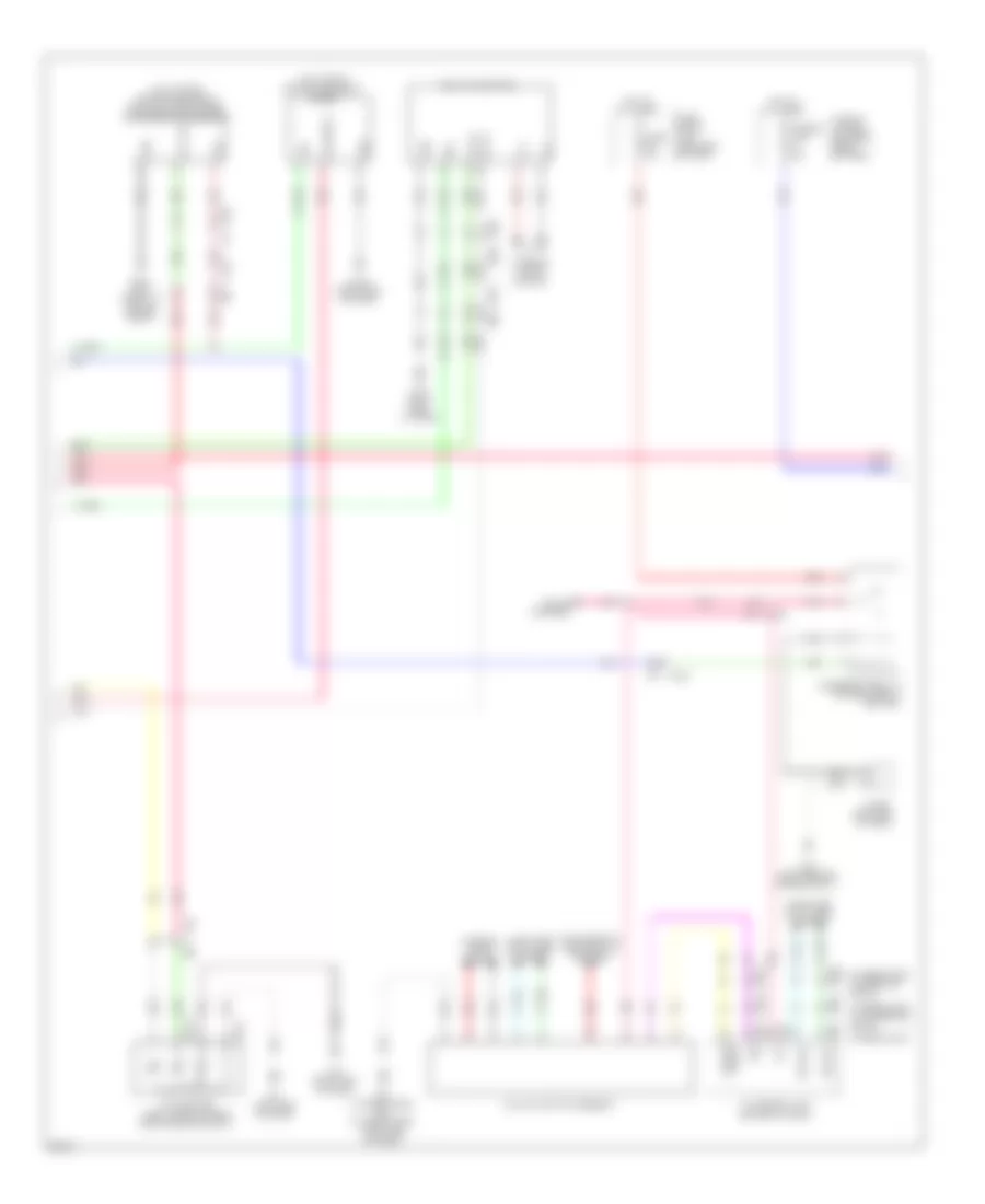
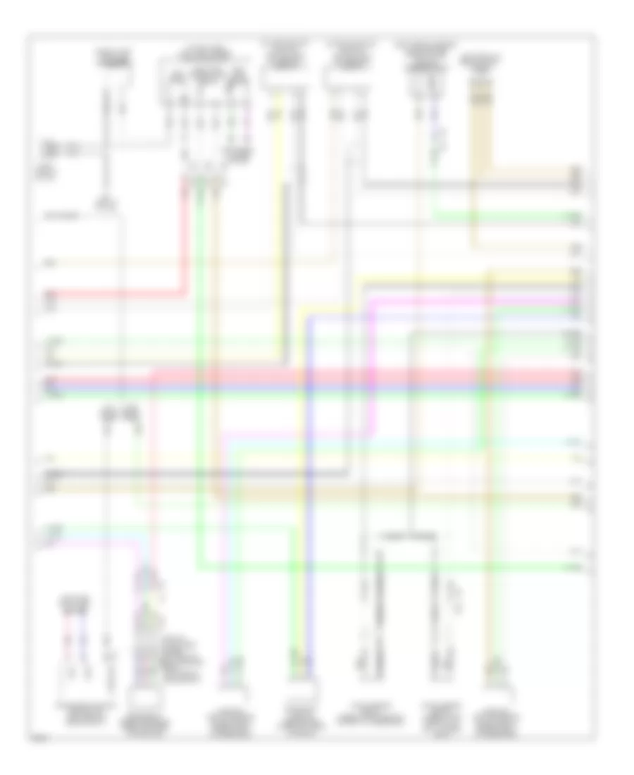
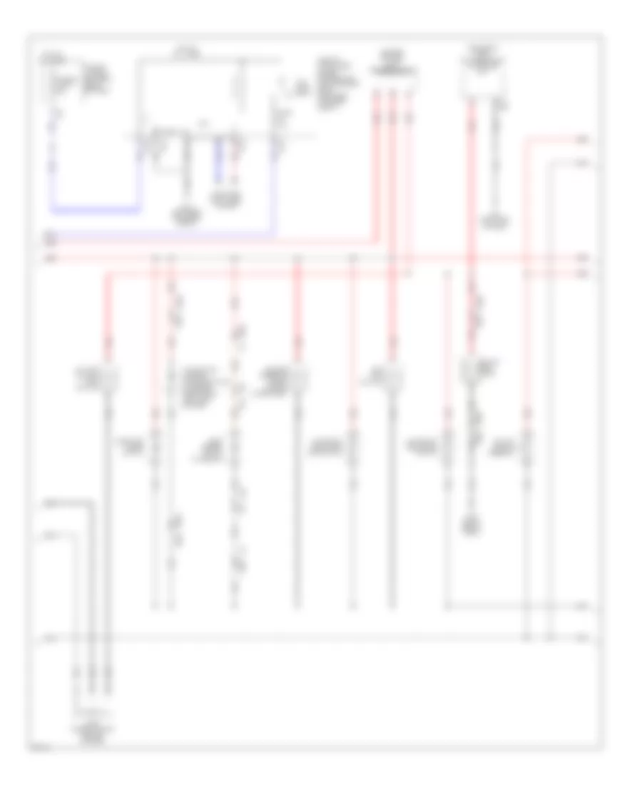
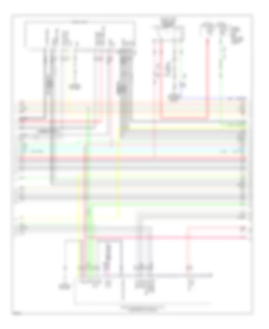
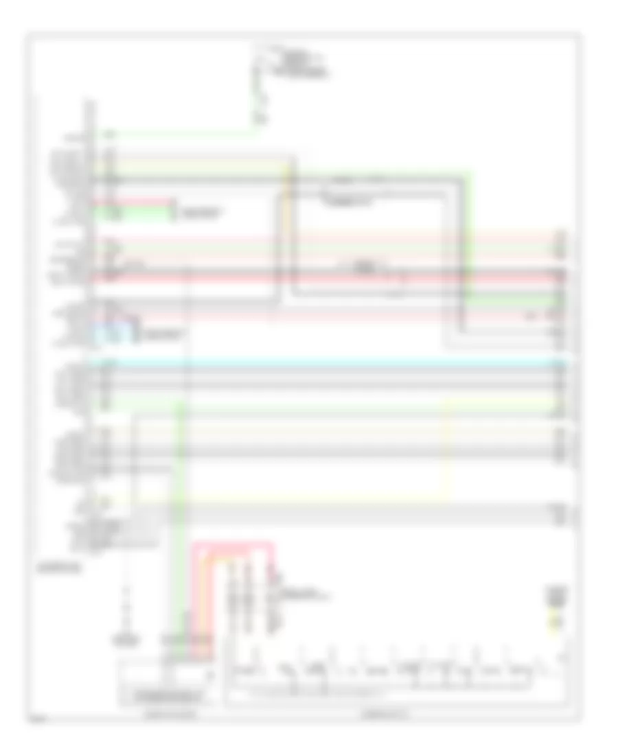
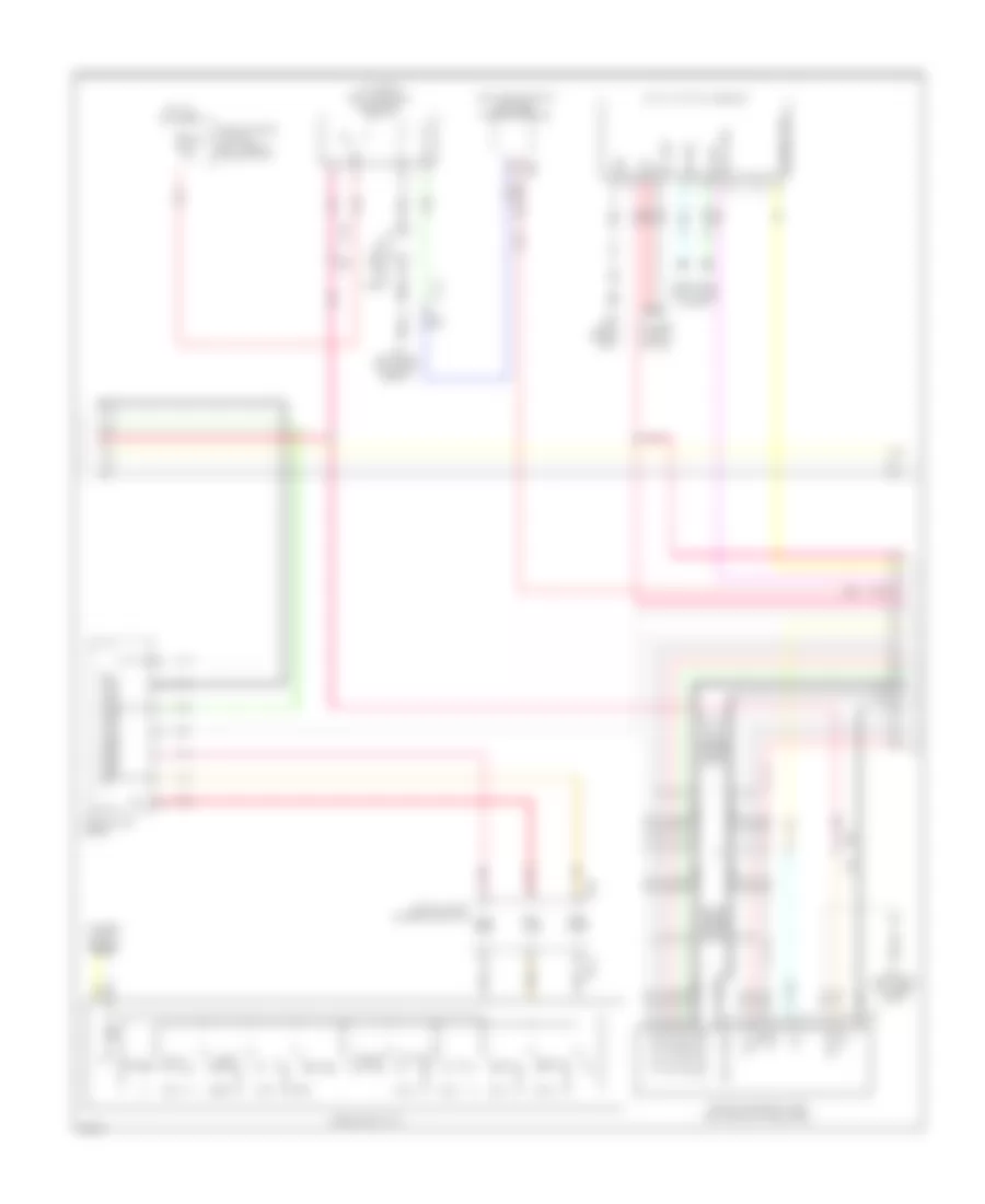
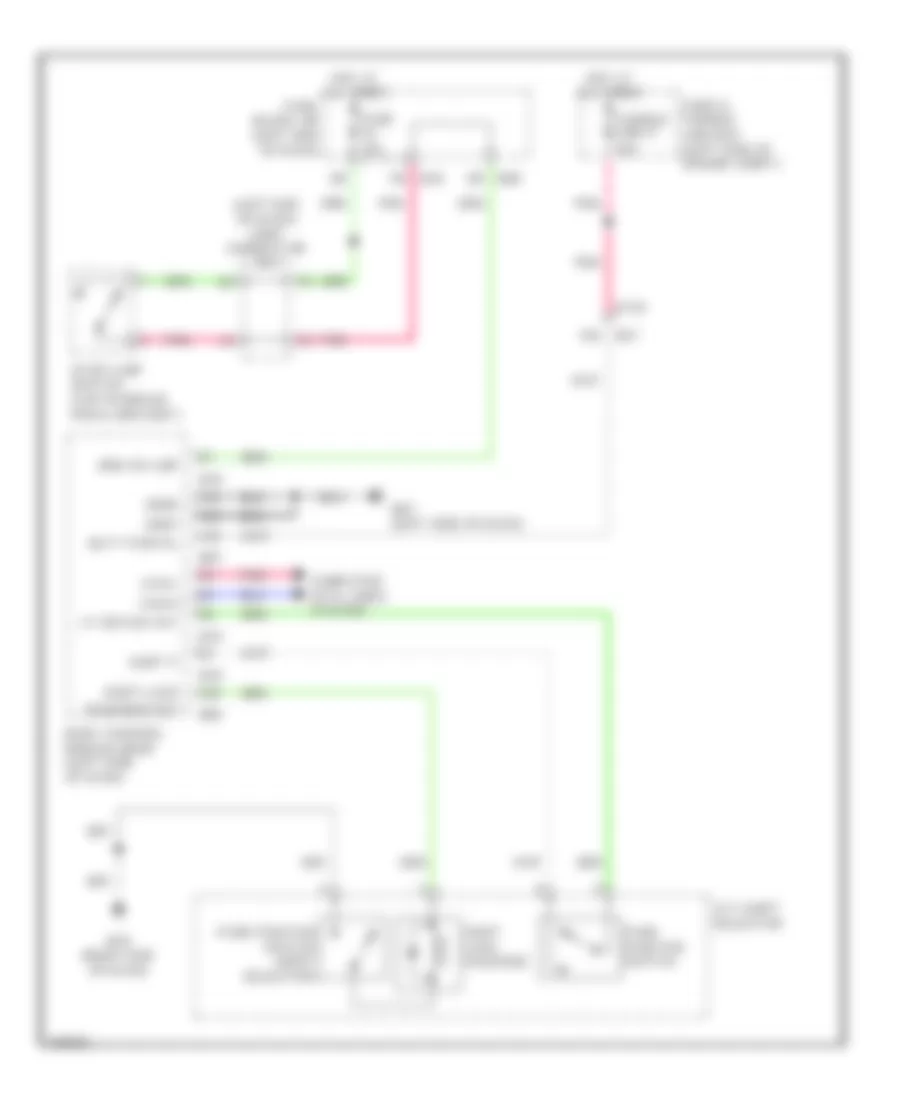
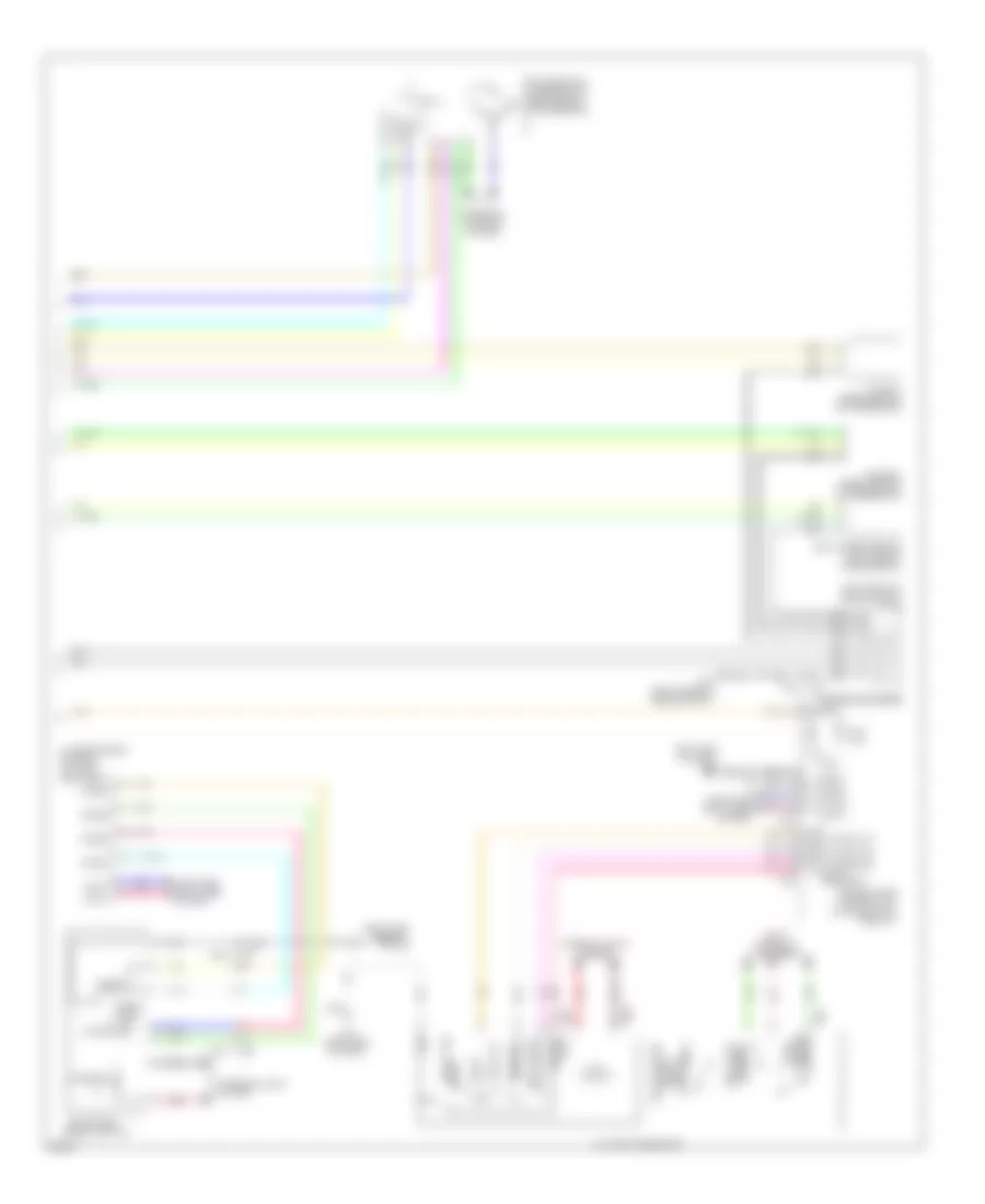
AIR CONDITIONING
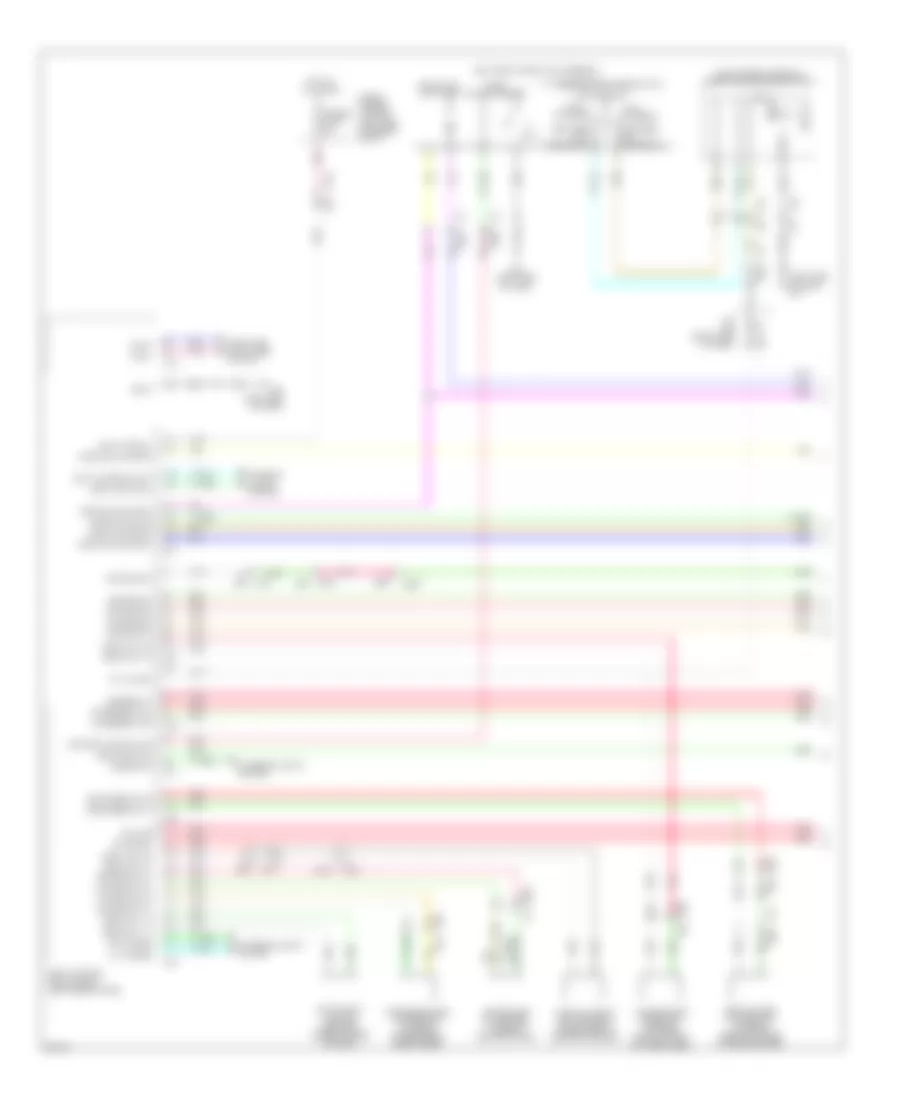
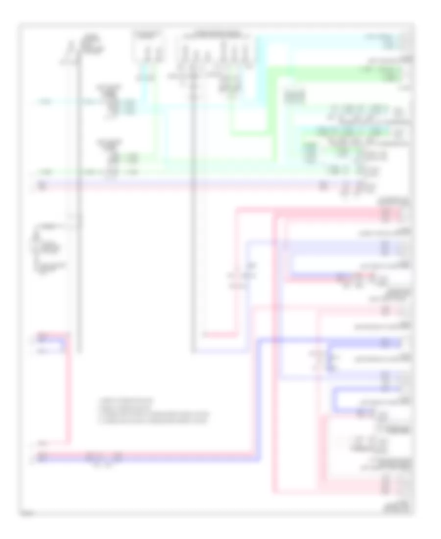
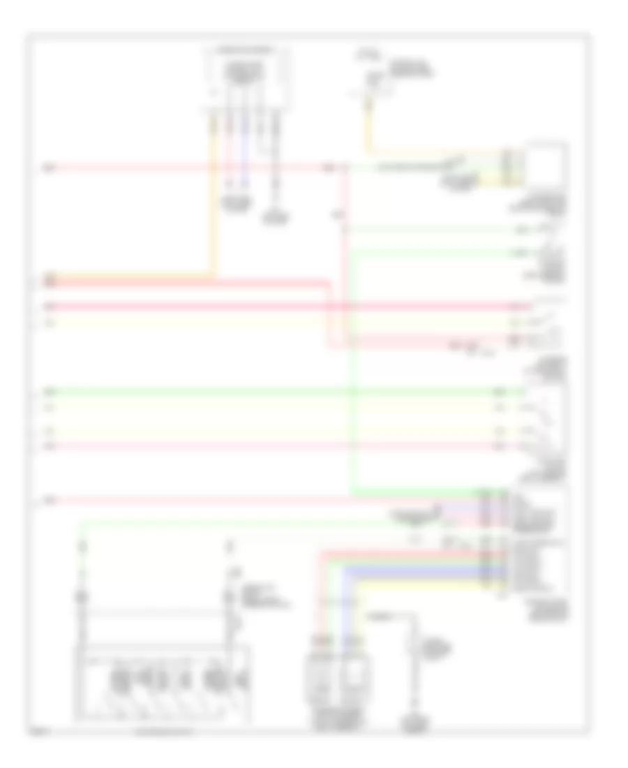
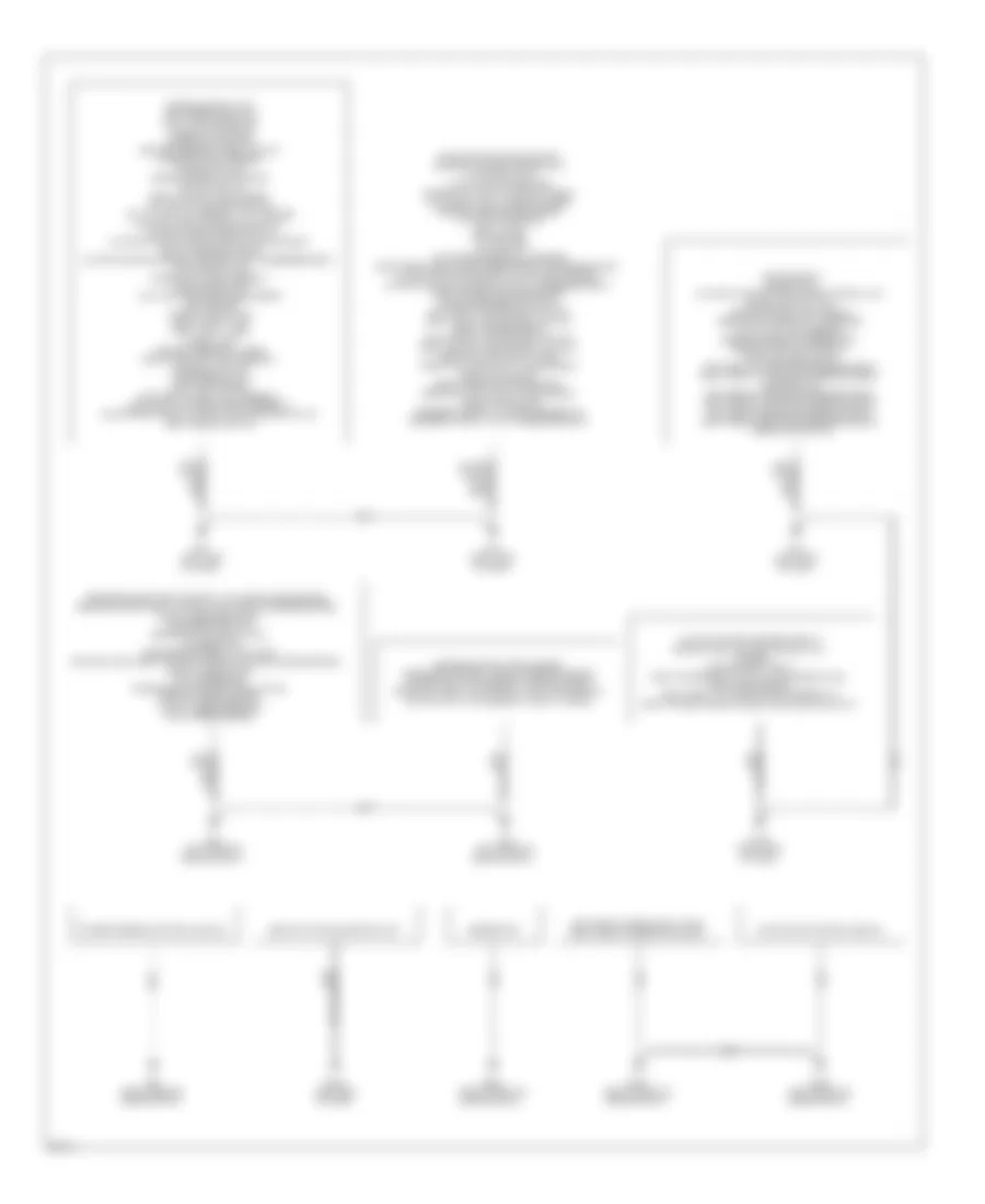
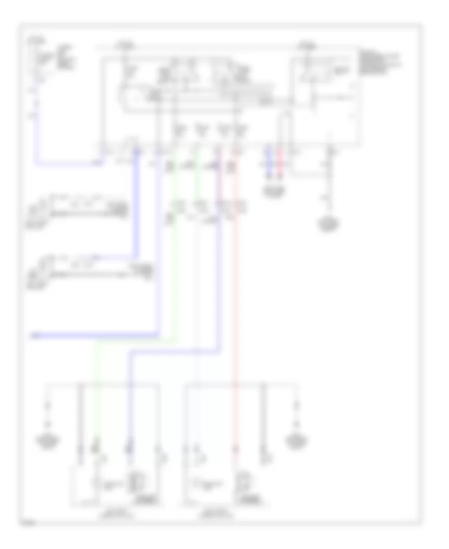
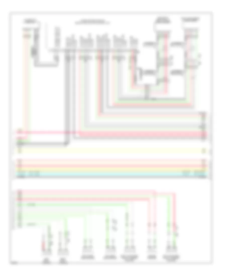
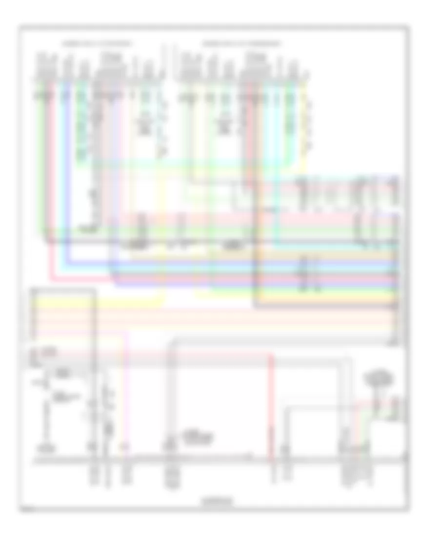
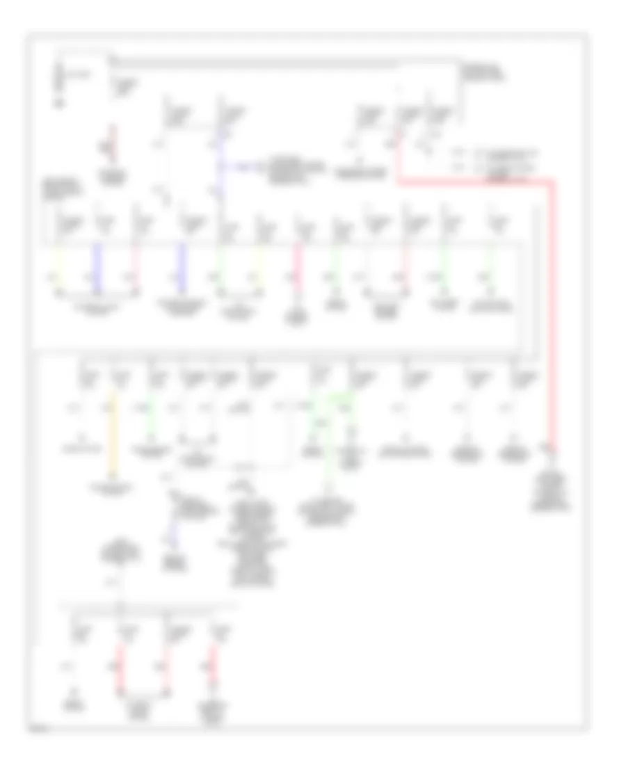
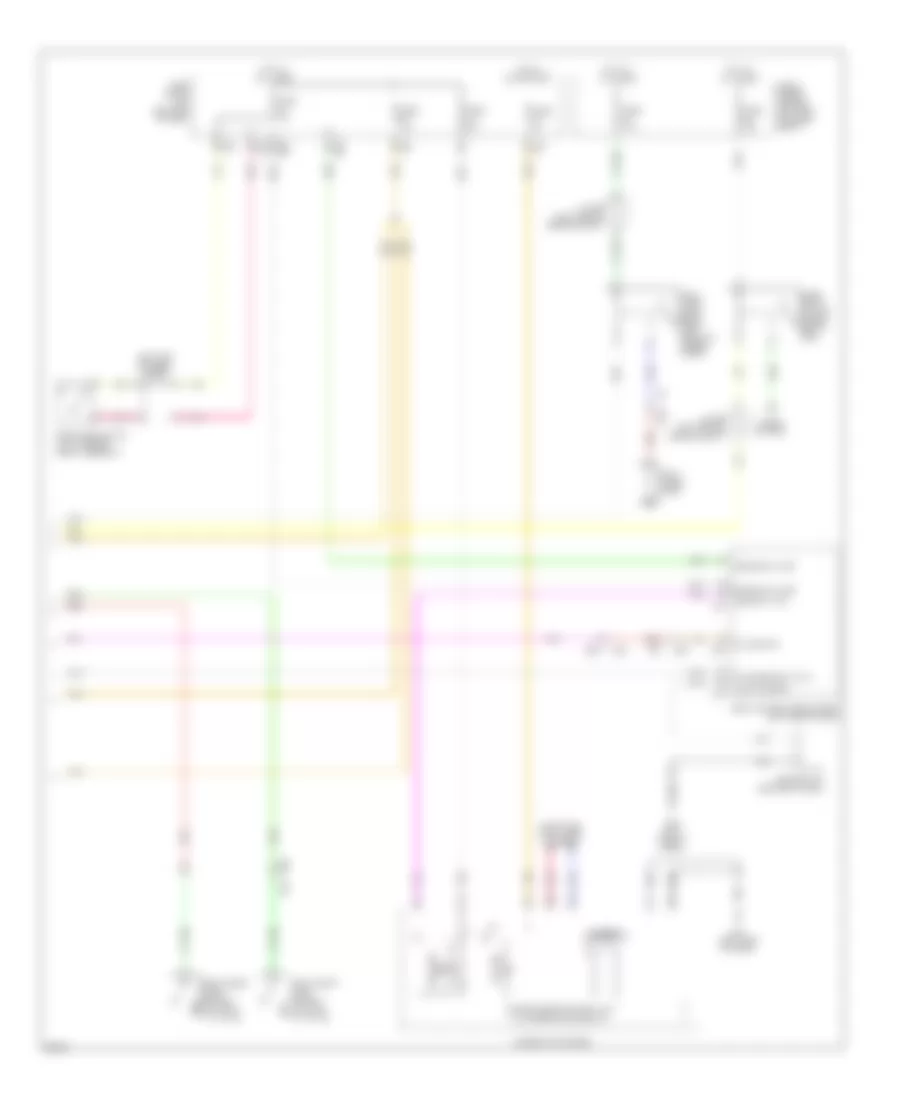
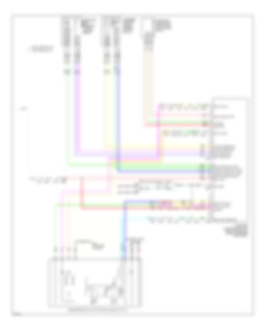
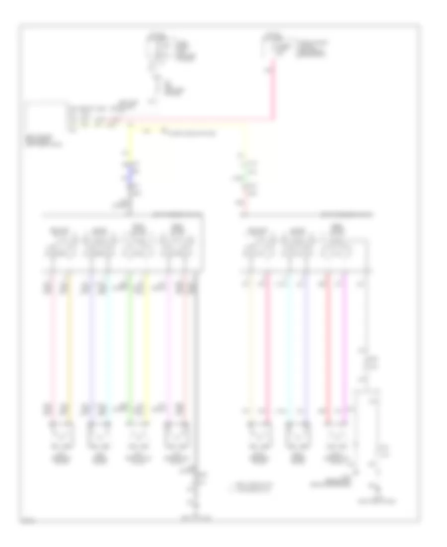
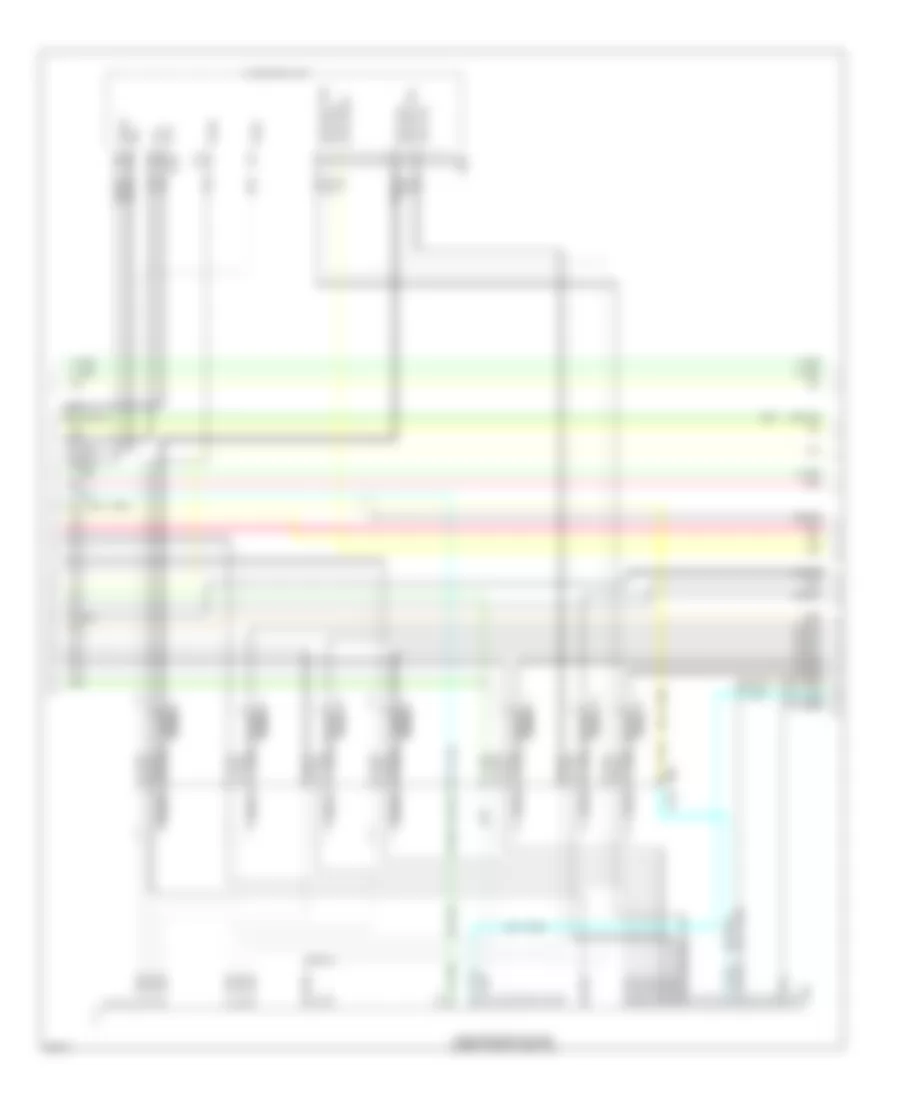
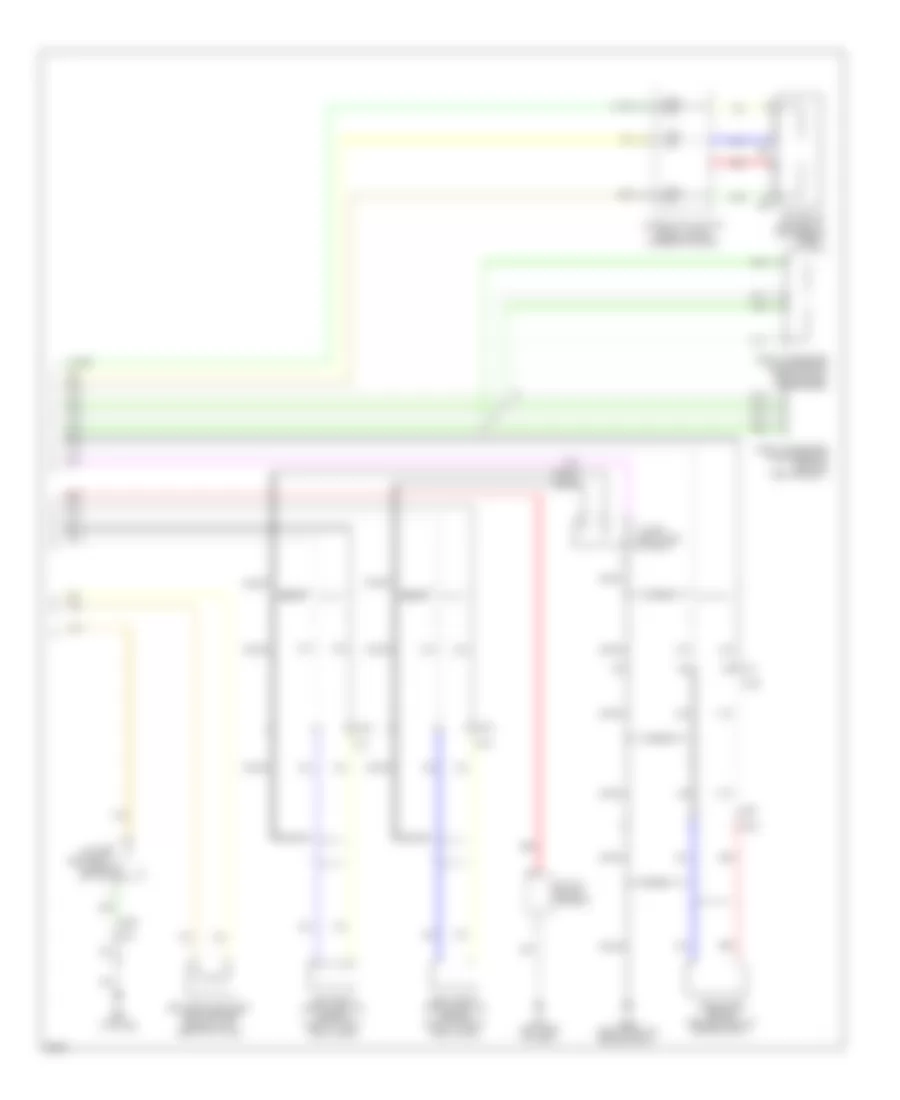
Automatic A/C Wiring Diagram (1 of 4) for Infiniti JX35 2013
 https://portal-diagnostov.com/license.html
Automotive Electricians Portal FZCO
Automotive Electricians Portal FZCO
https://portal-diagnostov.com/license.html
https://portal-diagnostov.com/license.html
Automotive Electricians Portal FZCO
Automotive Electricians Portal FZCO
List of elements for Automatic A/C Wiring Diagram (1 of 4) for Infiniti JX35 2013:
- (left side of dash) m57
- 13r
- 16p
- 94g
- A/c auto amplifier (lower center of dash)
- Actr (lin)
- Actr gnd
- Amb sens
- Amp
- B101
- B161
- Batt
- Can-h
- Can-l
- Computer data lines system
- Driver side air mix door motor (lower left side of hvac unit)
- E152
- E28
- Fan f/b (booster)
- Fan f/b (cooler)
- Fan out (booster)
- Fan out (cooler)
- Fr fan pwm
- Front blower motor (bottom of front heating/cooling unit)
- Front blower motor relay
- Front mode door motor (upper left side of hvac unit)
- Fuse & fusible link box (left side of engine compt)
- Fuse 10a
- Fuse 15a
- Fuse 20a
- Fuse 30a
- Fuse 5a
- Fuse block (j/b) (left end of dash)
- Gas sens
- Gnd
- Gnd (power)
- Hot at all times
- Hot in on or start
- Ign
- Ign 2
- Inc sens
- Int sens
- Intake door motor (right side of front heating unit)
- Ion on/off
- M127
- M157
- M31
- M61 (left side of dash)
- M68
- M79 (right end of dash)
- M84
- Mode 1
- Mode 2
- Mode 3
- Mode 4
- Passenger side air mix door motor (right side of hvac unit)
- Pnk
- Ptc 1
- Ptc 2
- Rear air mix door motor (right side of hvac unit)
- Rear mode door motor (left rear of rear heating/ cooling unit)
- Rear shut-off door motor (left front of rear heating/cooling unit)
- Red
- Rr rx
- Rr tx
- Seats system
- Seats system computer data lines system
- Sens gnd
- Strg htr rly
- Strg htr sw
- Sun sens
- Tan
- Vactr
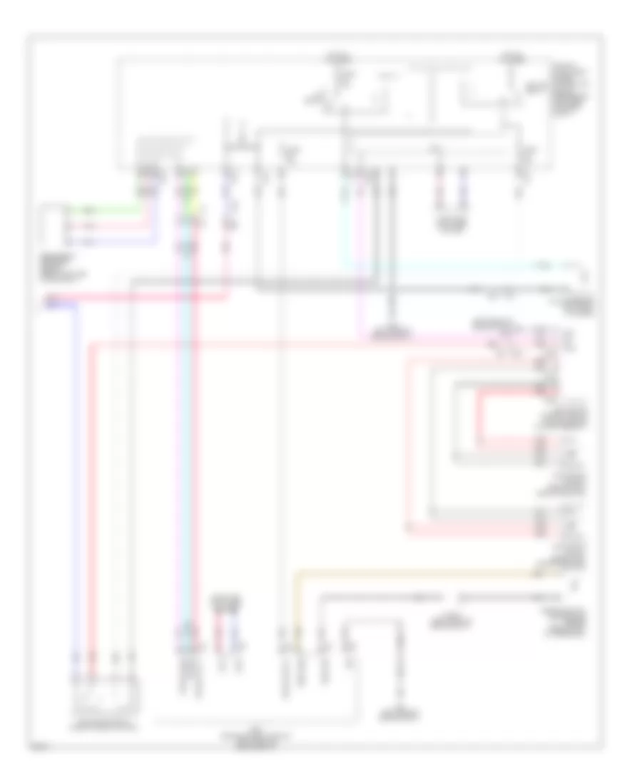
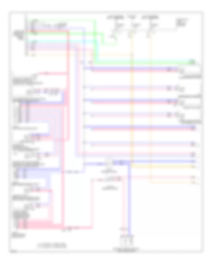
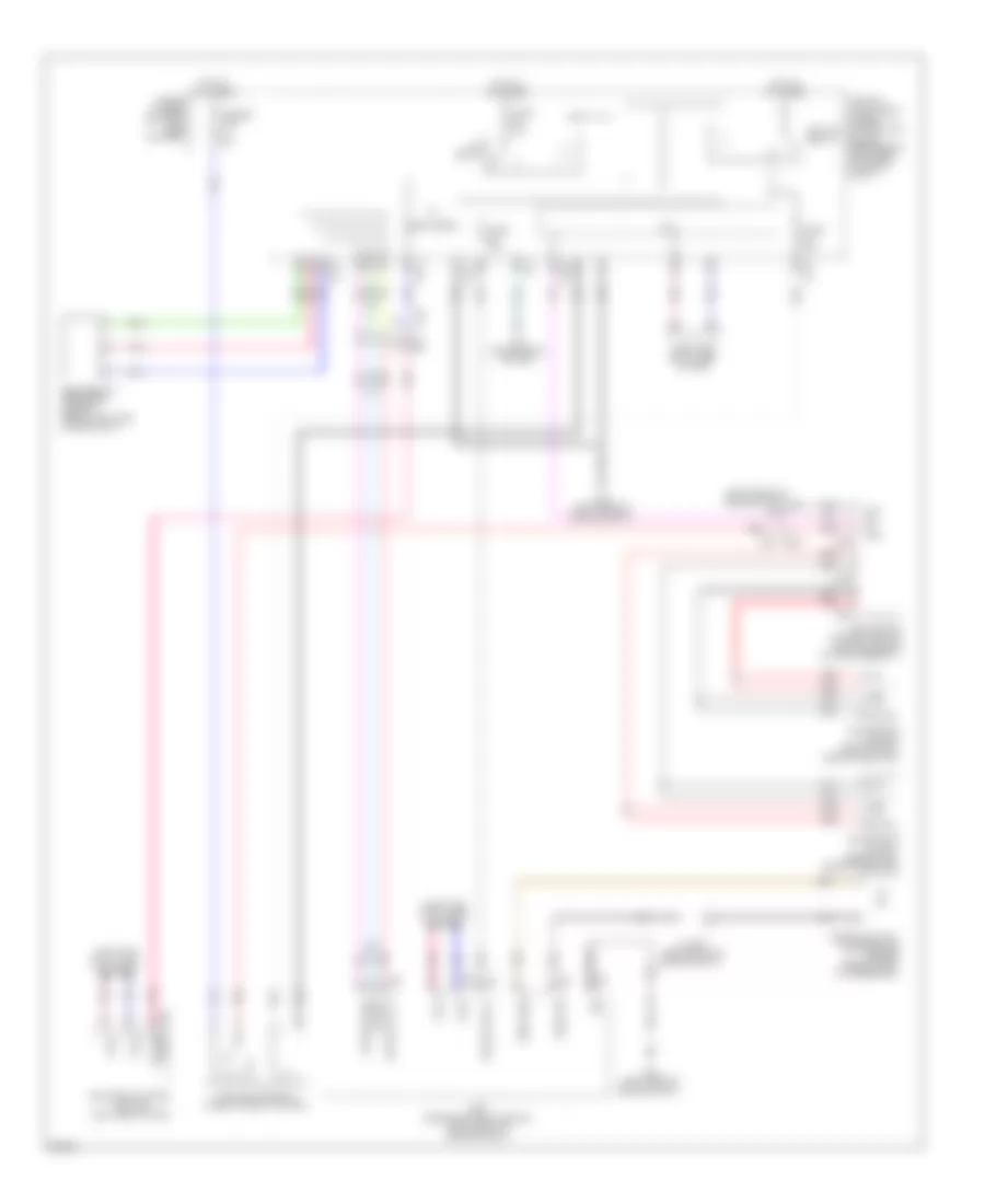
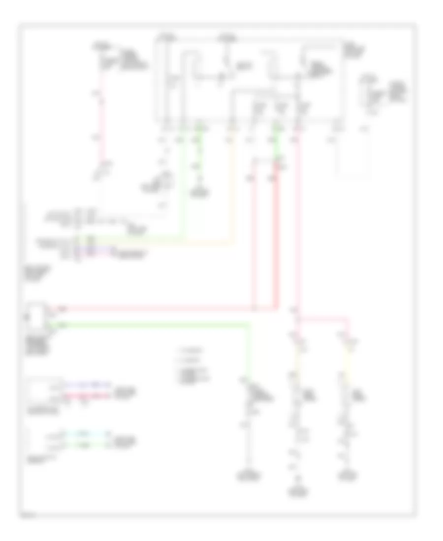
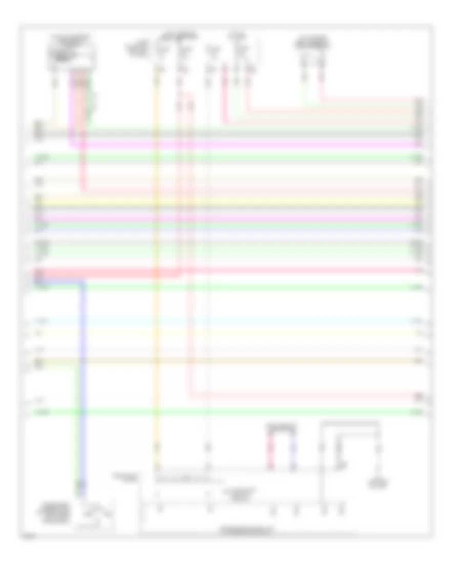
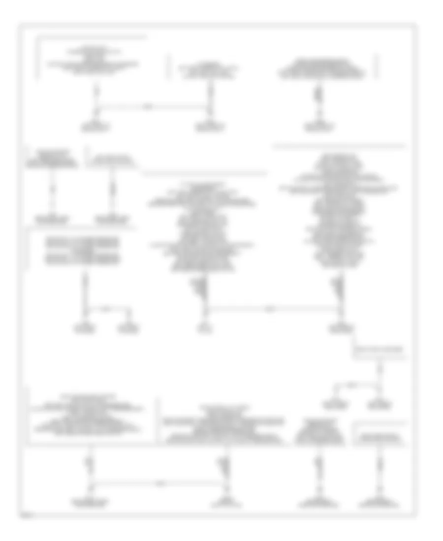
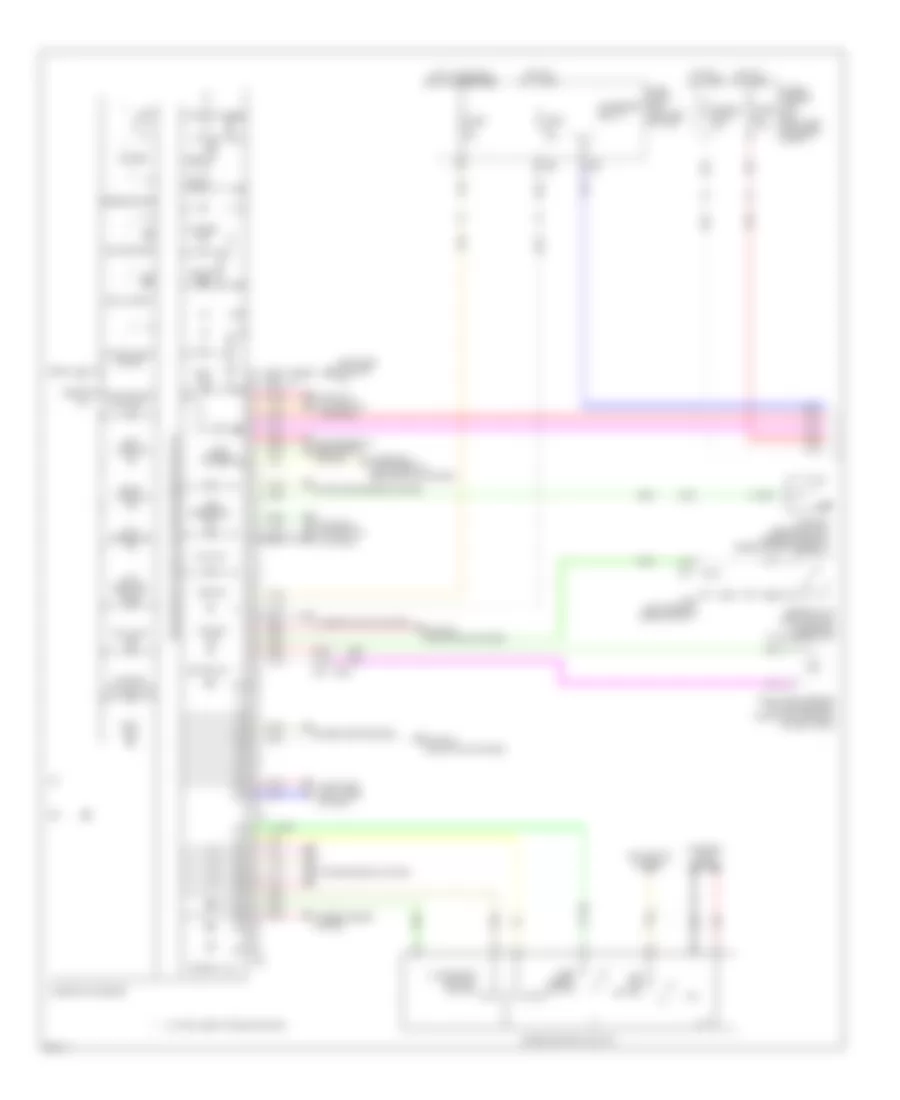
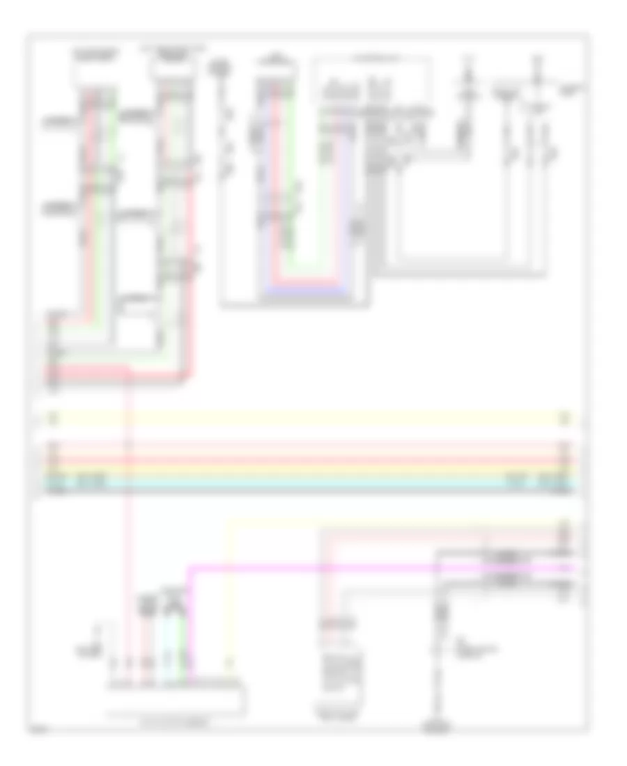
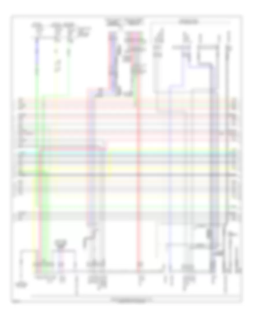
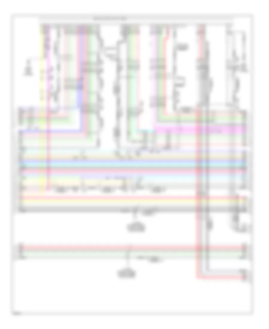
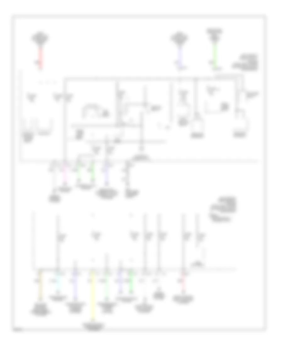
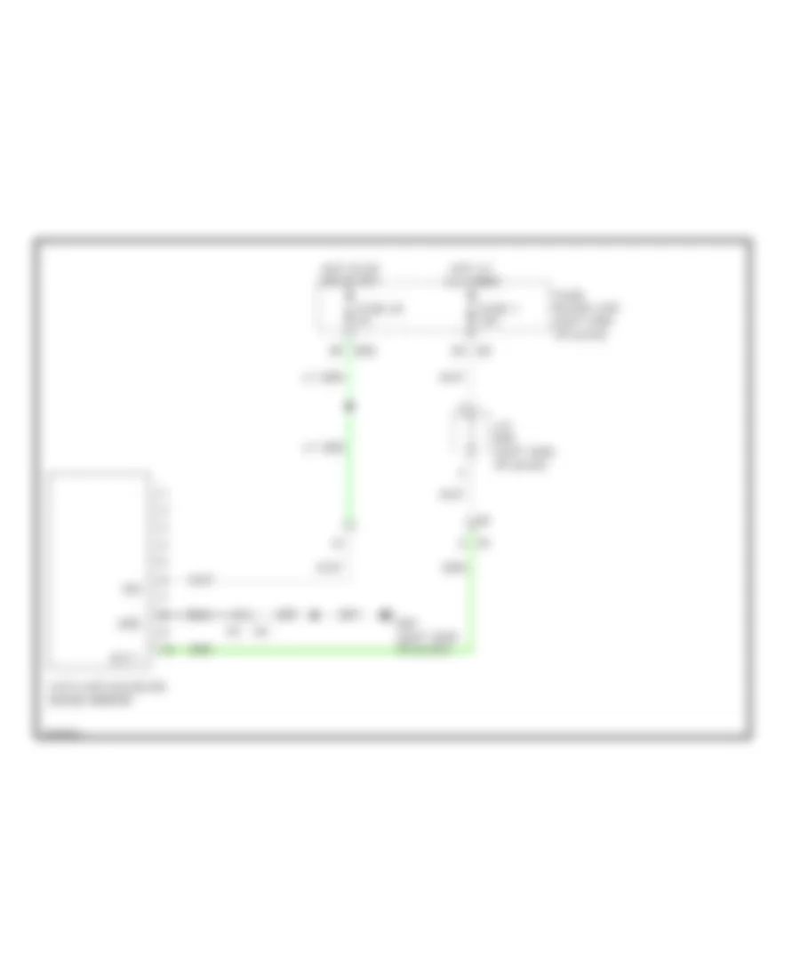
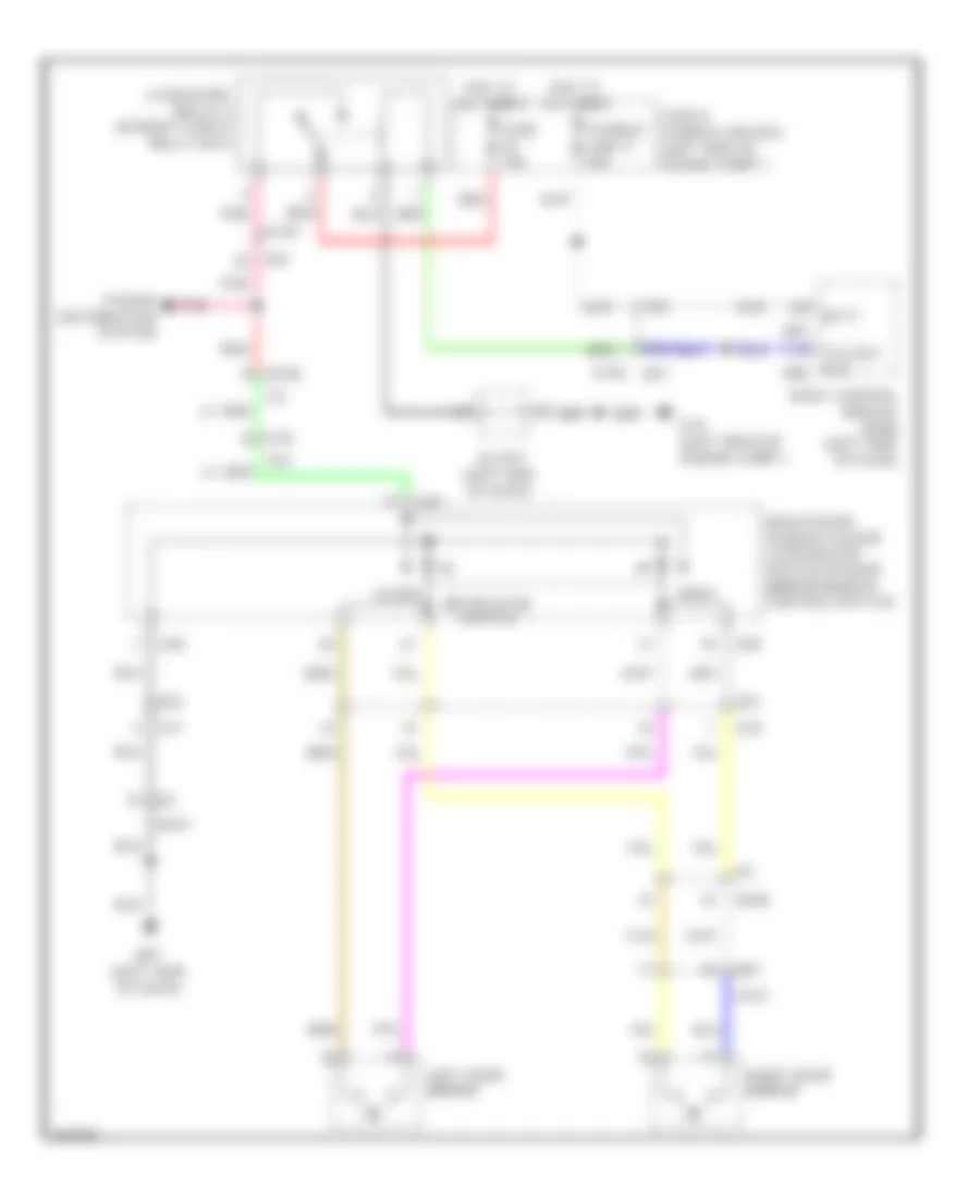
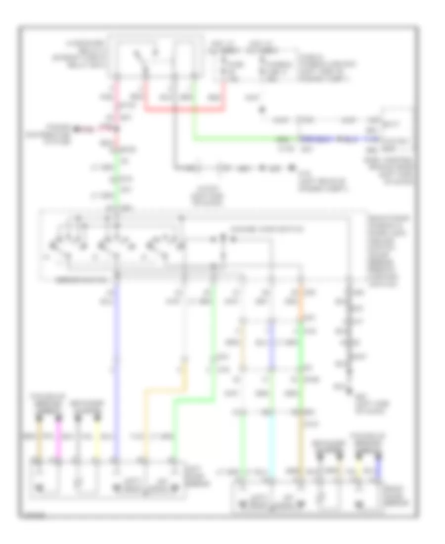
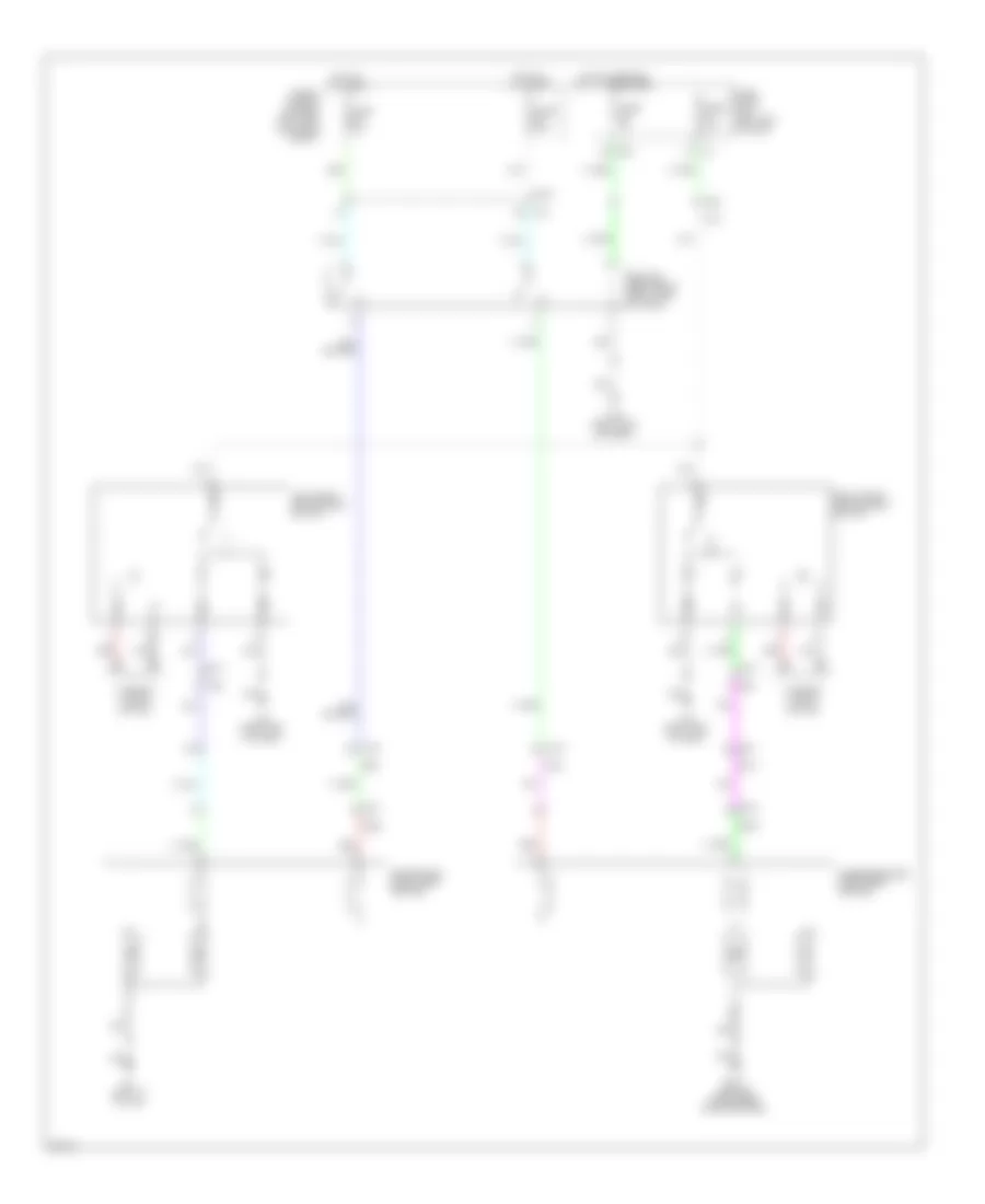
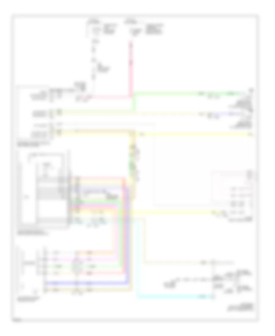
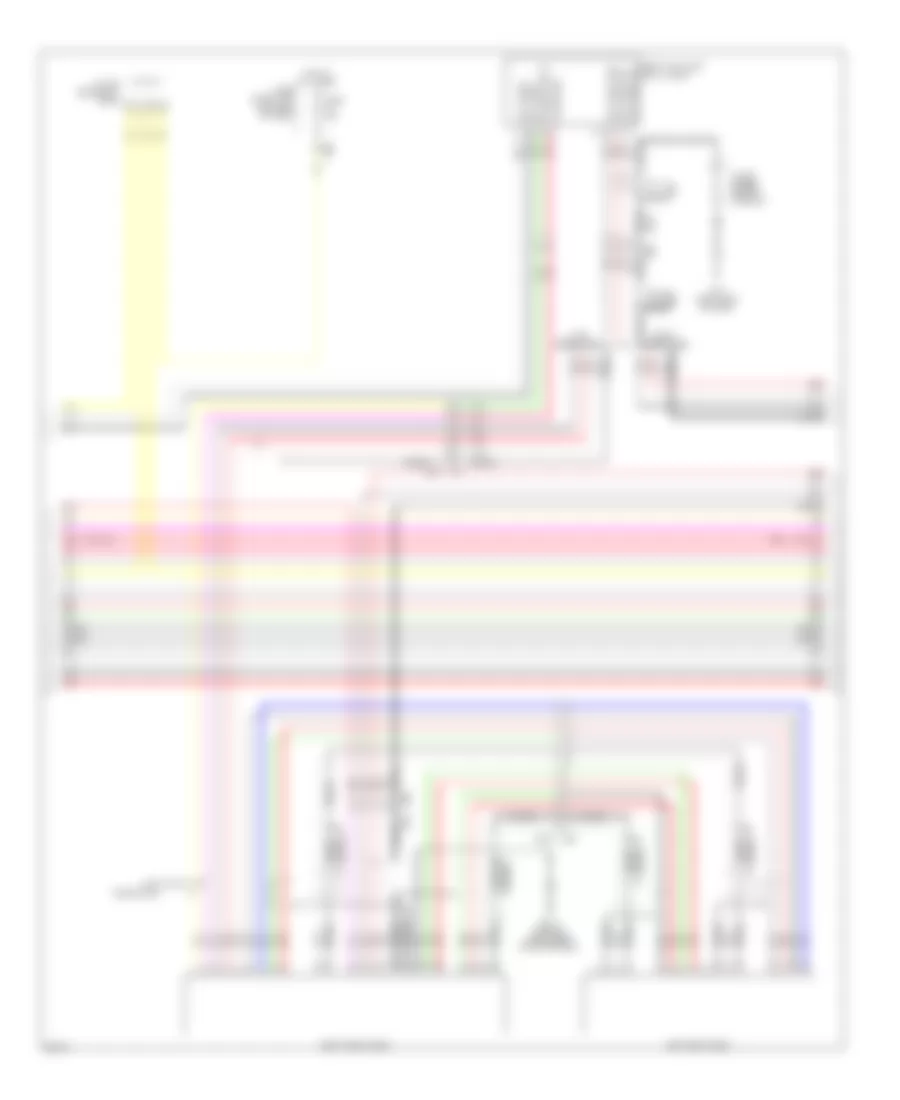
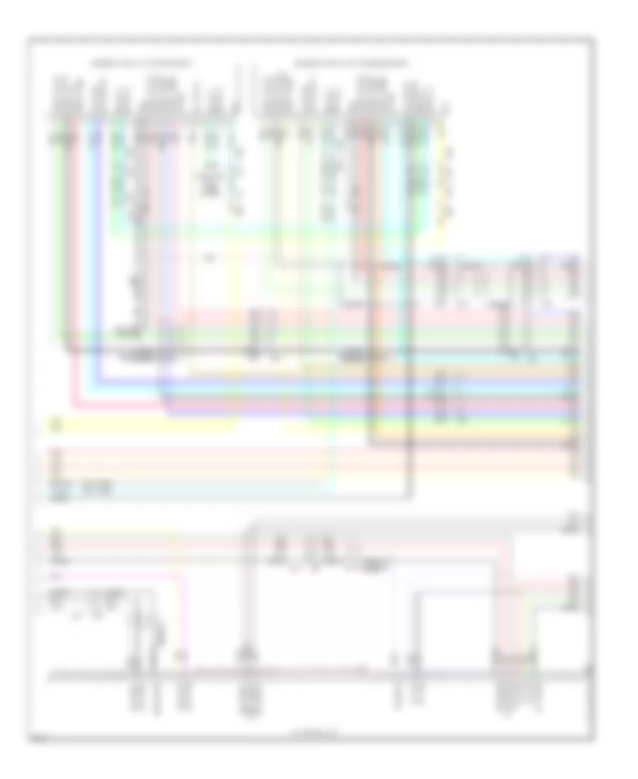
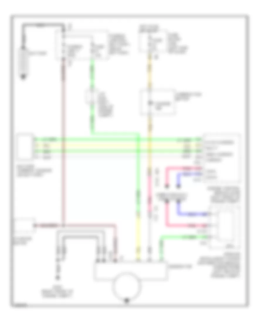
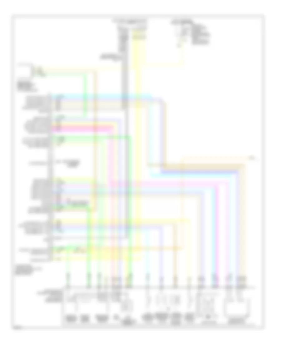
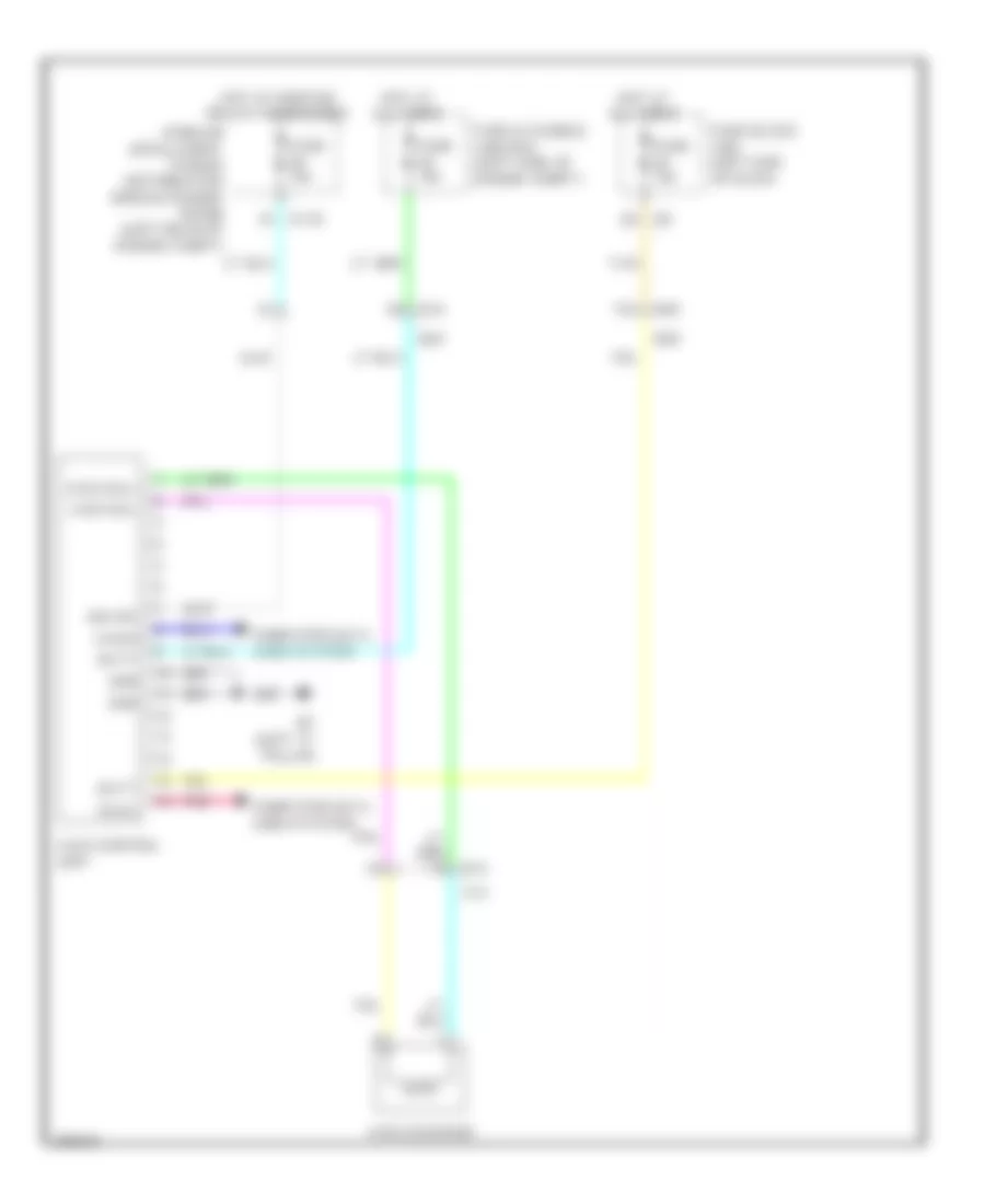
Automatic A/C Wiring Diagram (2 of 4) for Infiniti JX35 2013
List of elements for Automatic A/C Wiring Diagram (2 of 4) for Infiniti JX35 2013:
- (in fuse & relay box (rh)) ptc relay 1
- (in fuse & relay box (rh)) ptc relay 2
- (left side of dash) bcm (body control module)
- (right side of cargo area) rear blower motor 2
- 12g
- 13g
- 37g
- 38g
- Acc rely out
- Ambient sensor (behind center of front bumper)
- B132 (base of right "d" pillar)
- Blwr fan rely out
- Can-h
- Can-l
- Computer data lines system
- Drive mode select switch
- E152
- E209
- E26
- Eco
- Ign usm out 1
- In-vehicle sensor (lower left center of dash)
- Intake sensor (right center of dash, on cooling unit)
- Interior lights system
- J/c m09 (right side of dash)
- M19
- M217
- M31
- M61 (left side of dash)
- M65
- M79 (right end of dash)
- M8 b106
- M80
- Pnk
- Rear blower motor 1 (on rear heating/ cooling unit)
- Rear blower motor relay (right end of dash)
- Rear blower motor resistor 1 (bottom of rear blower motor)
- Rear blower motor resistor 2 (on rear blower motor 2 assembly)
- Red
- Snow
- Sport
- Standard
- Sunload sensor (top left side of dash)
- Tan
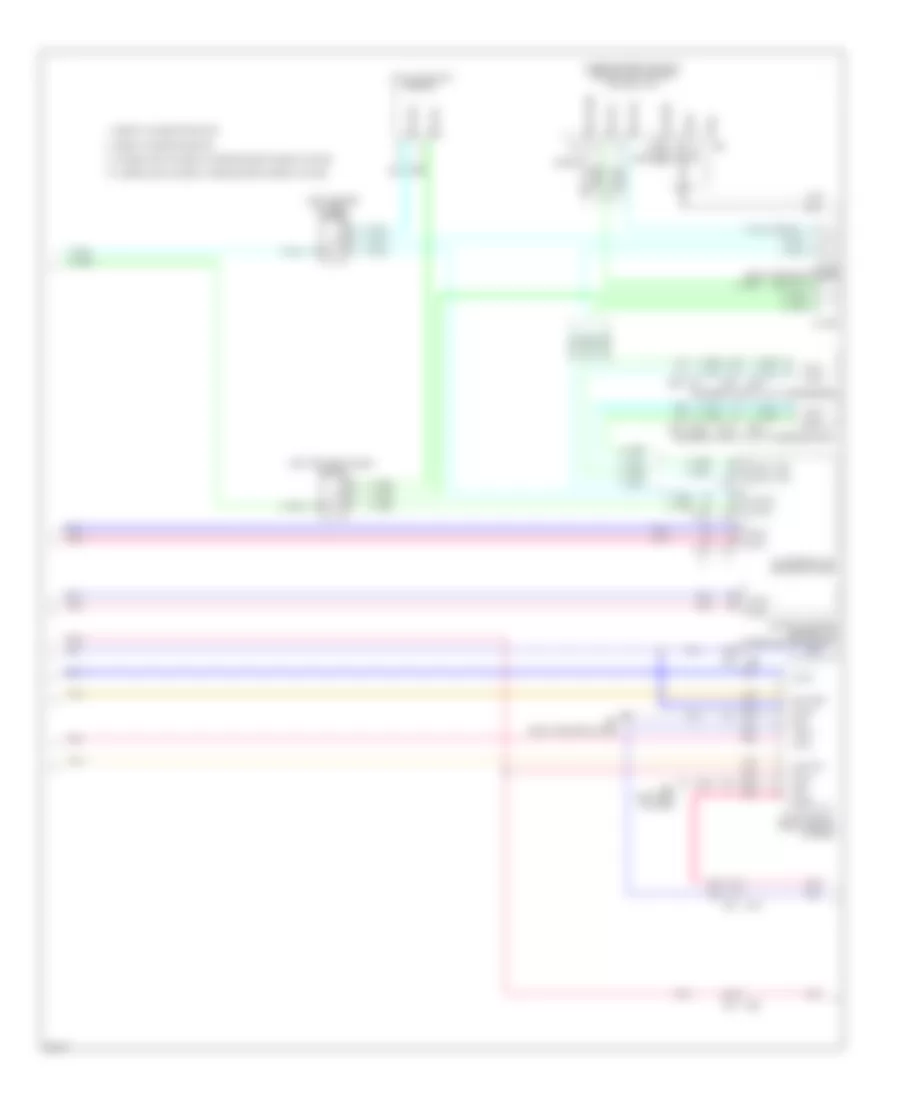
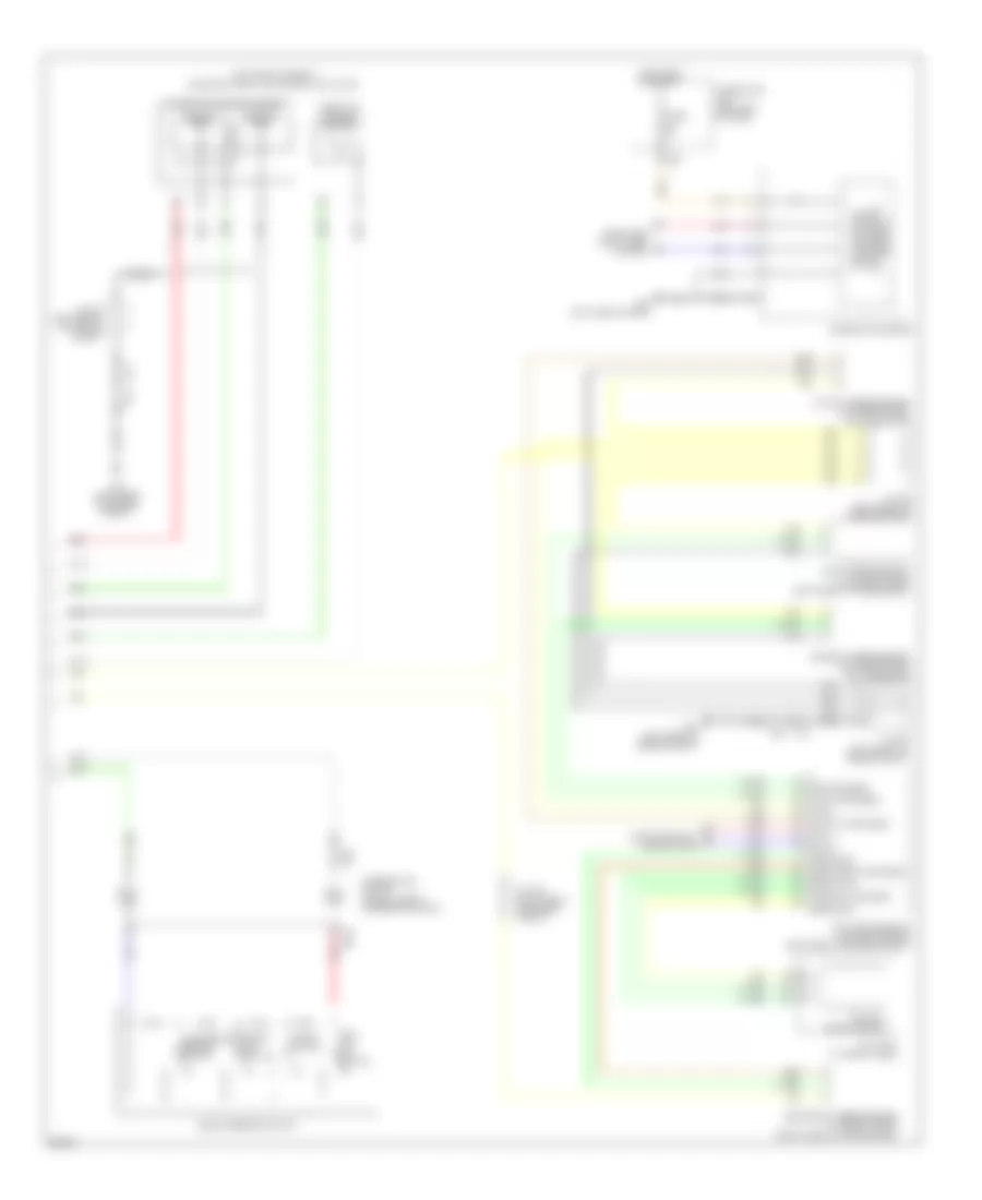
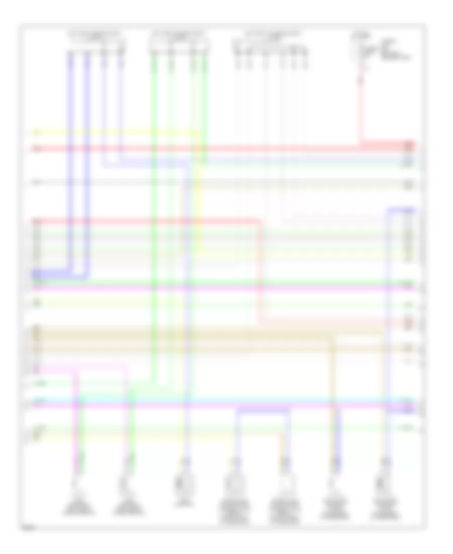
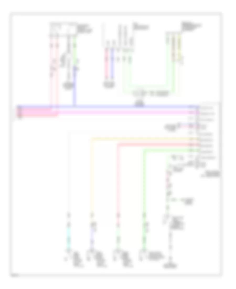
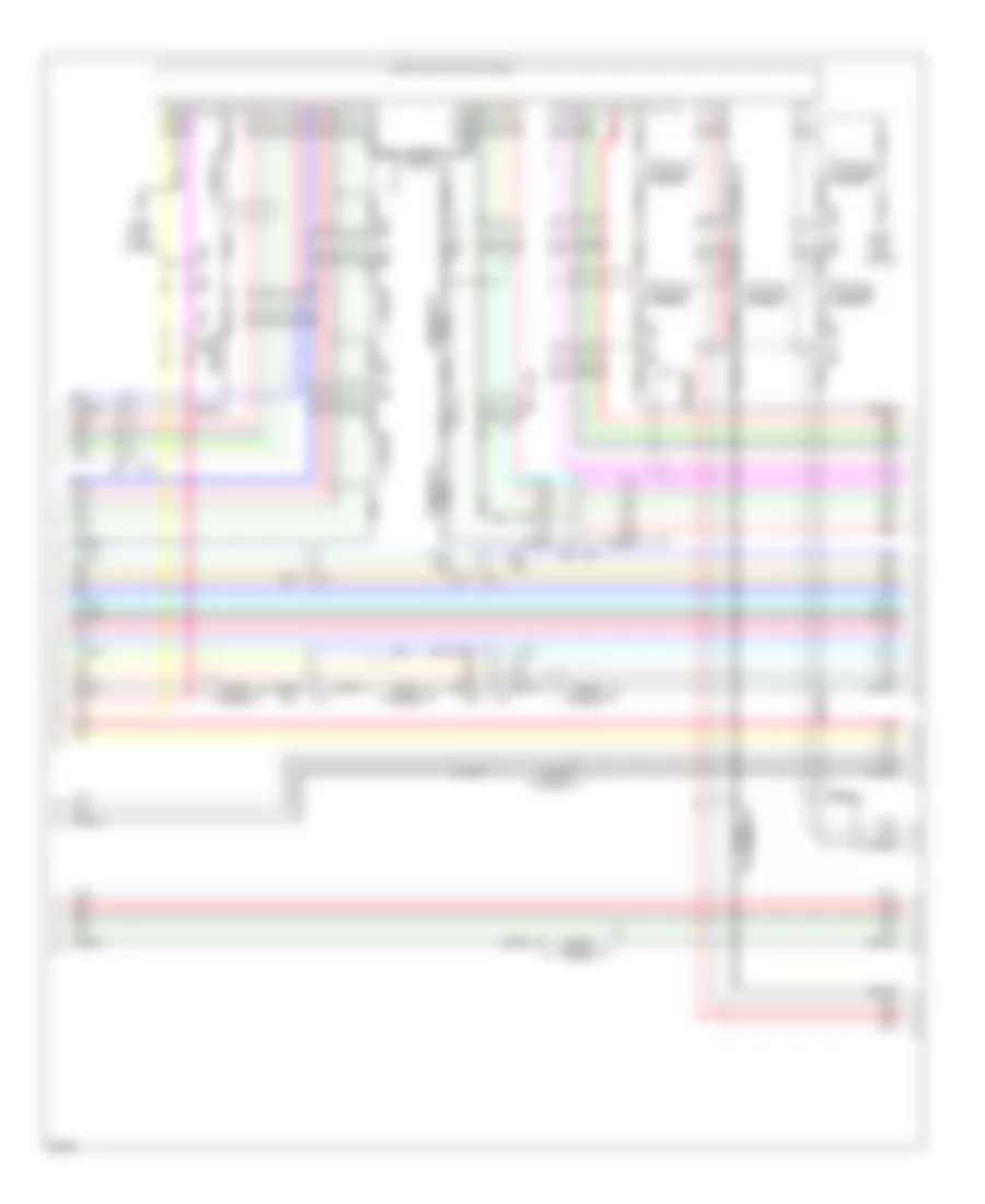
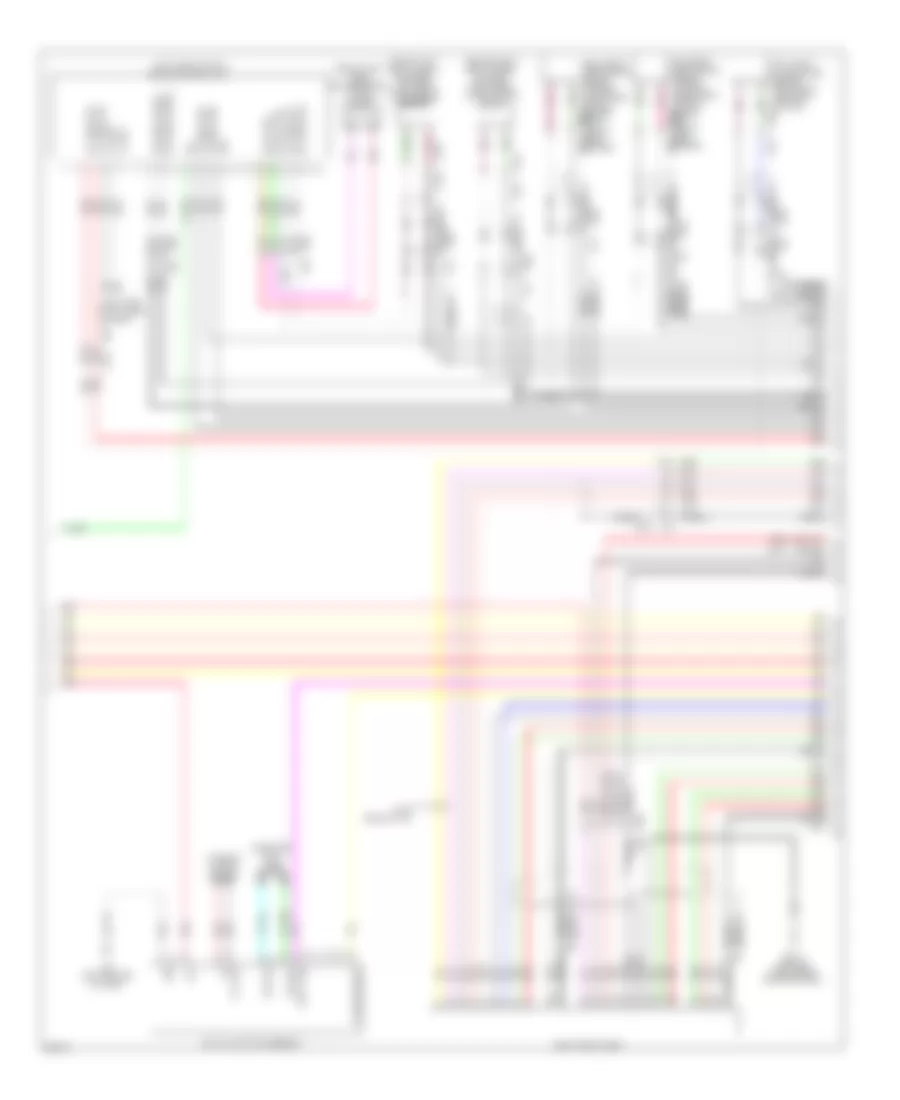
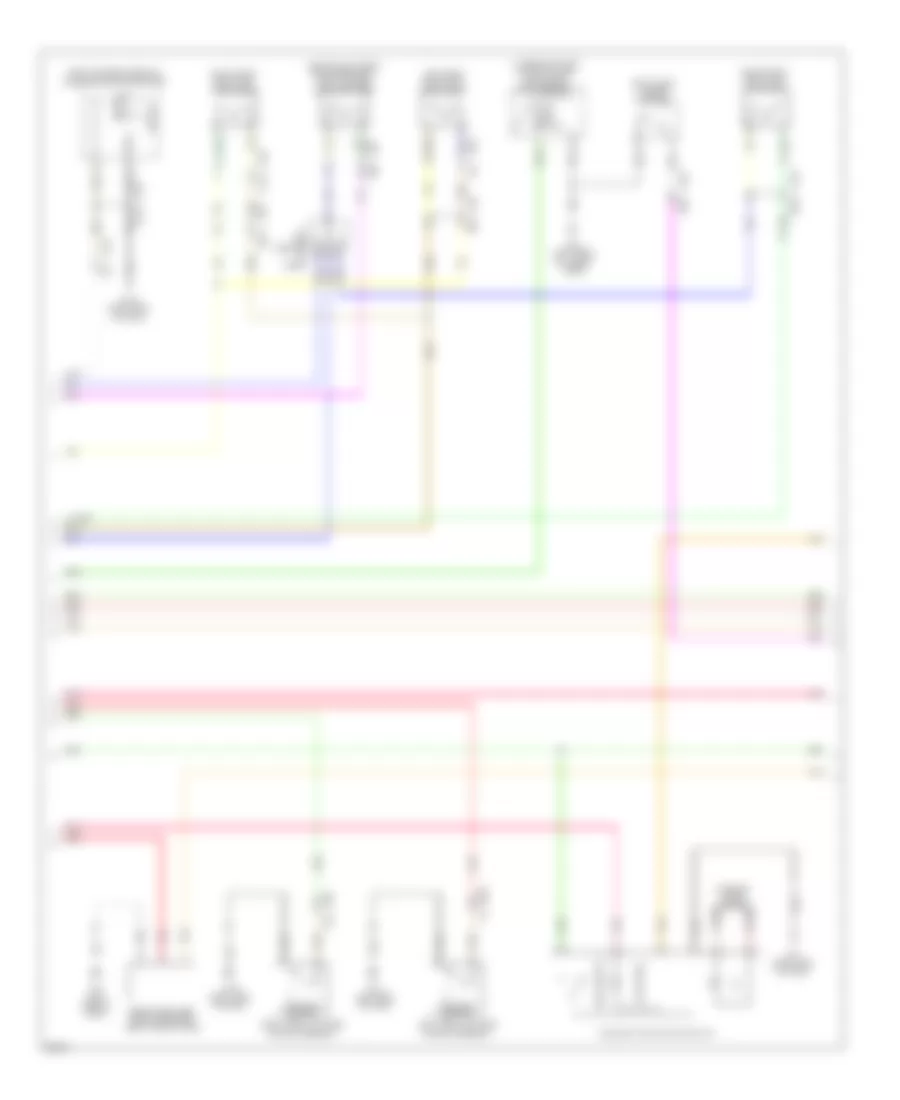
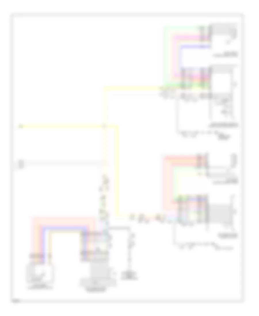
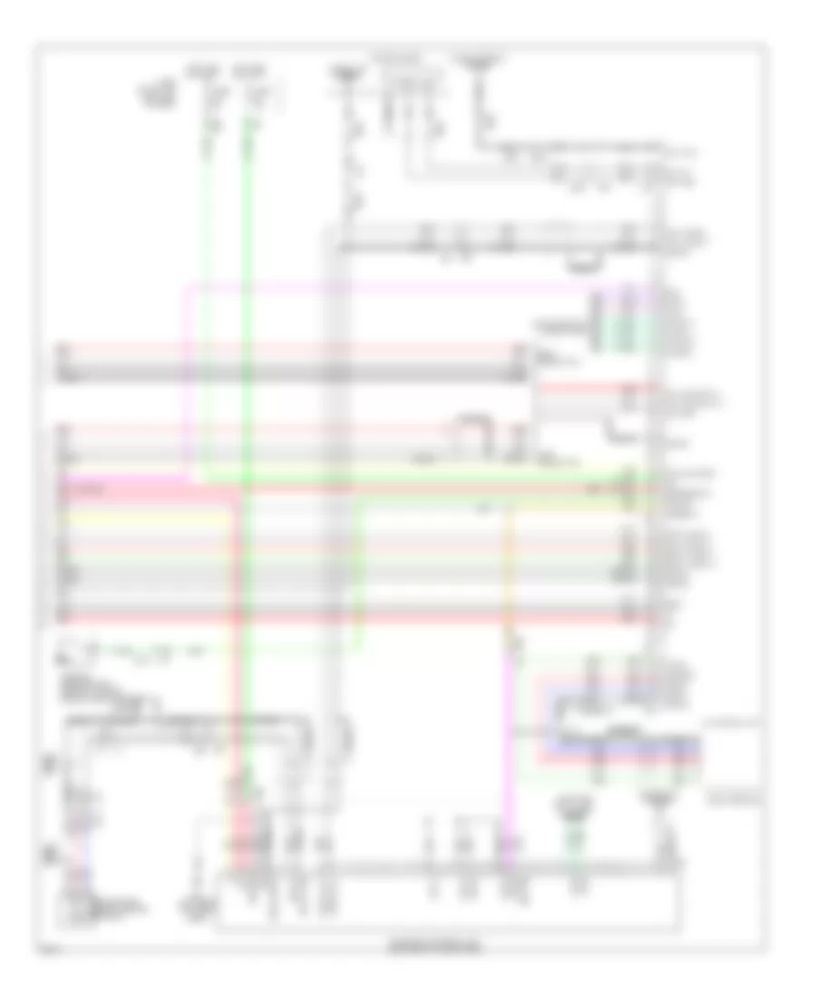
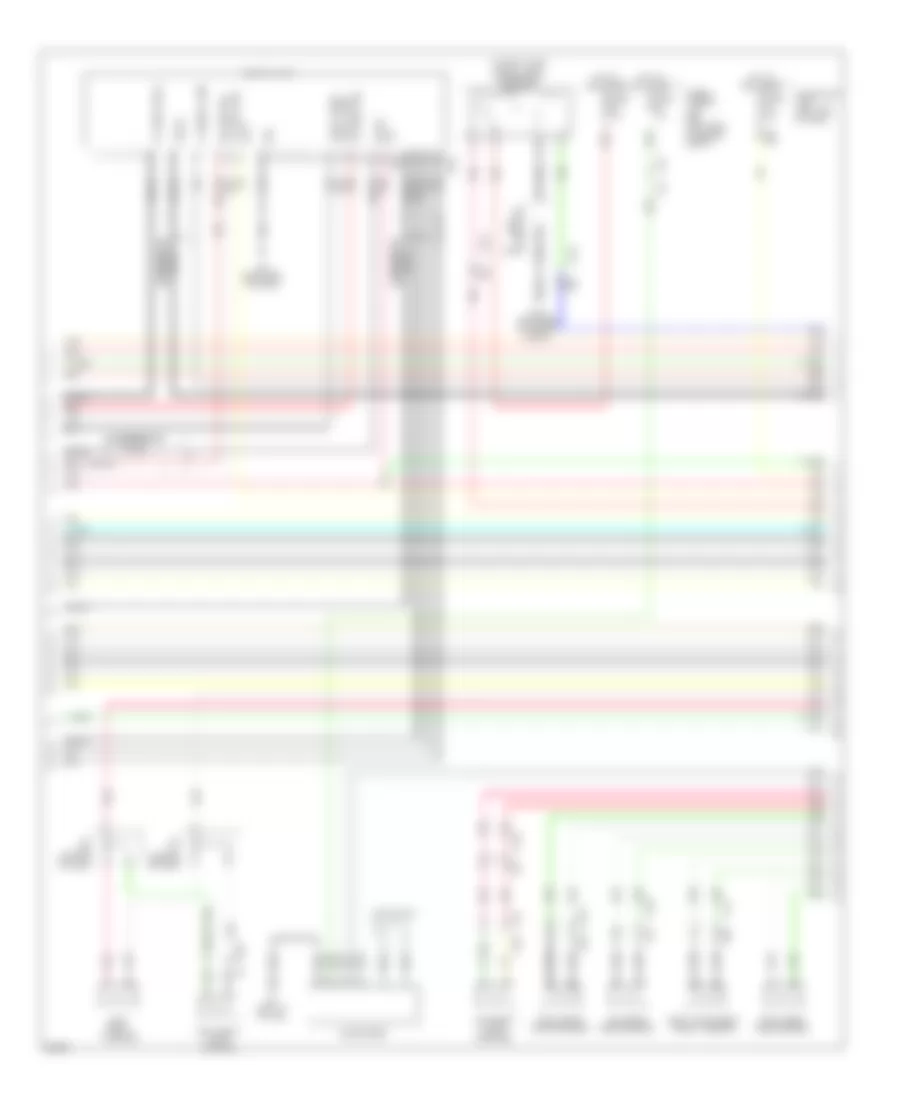
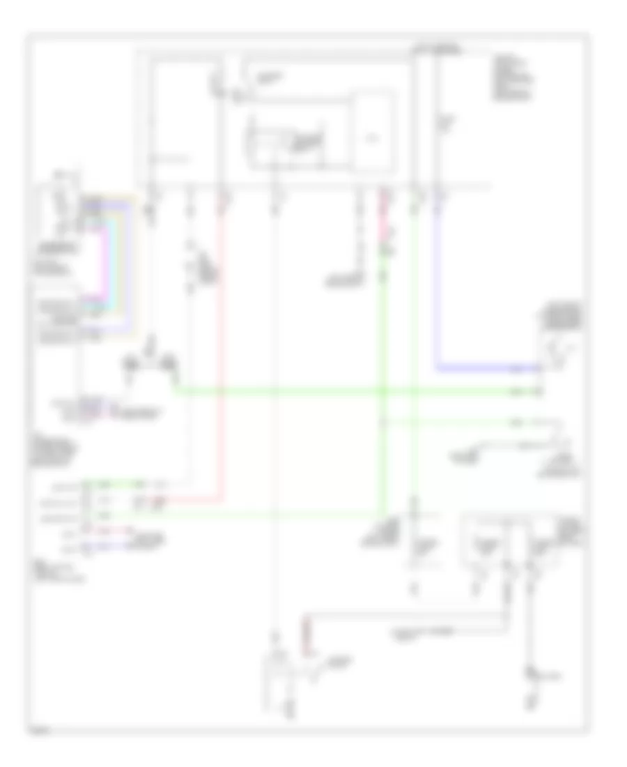
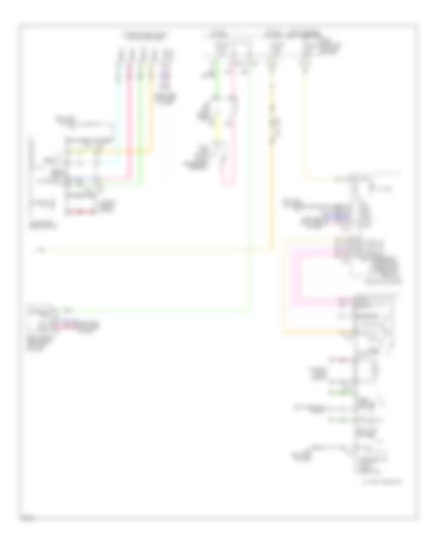
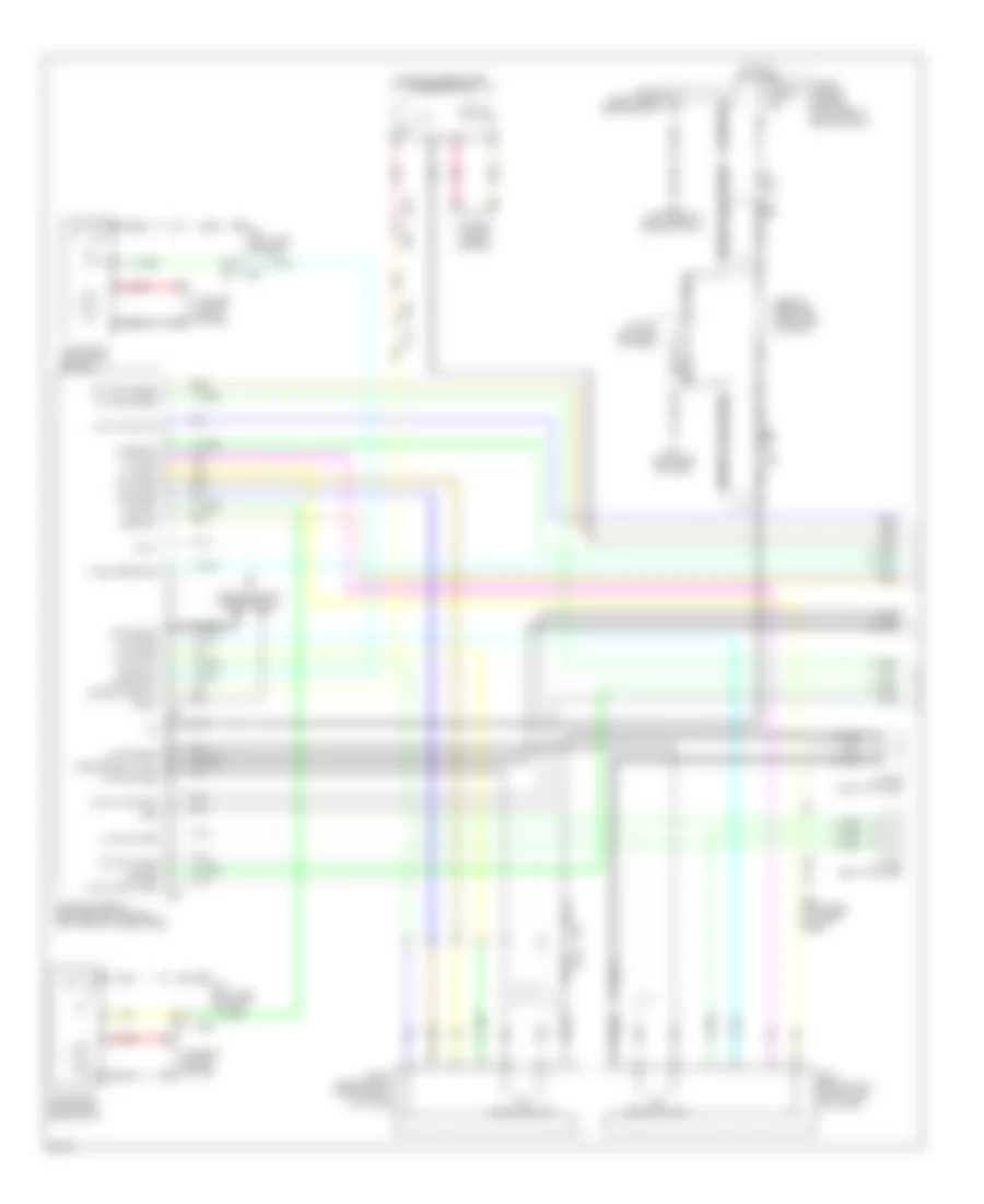
Automatic A/C Wiring Diagram (3 of 4) for Infiniti JX35 2013
List of elements for Automatic A/C Wiring Diagram (3 of 4) for Infiniti JX35 2013:
- (w/ climate controlled seat) exhaust gas/outside door detecting sensor
- (w/ climate controlled seat) ionizer
- 11g
- 21g
- 50g
- A/c & av switch assembly
- Acc
- Accessory relay 2 (in fuse & relay box (rh))
- Av control unit (center of dash)
- Cd(dvd)
- Computer data lines system
- E15 (left rear of engine compt)
- E152
- E152 m31
- E207
- E213 (left front of engine compt)
- E36
- Eject
- Fuse 10a
- Fuse block (j/b) (left end of dash)
- Fusible link box (battery) (near battery)
- Fusible link h 60a
- Gnd
- Hot at all times
- Ign
- Ill +
- Ill -
- Interior lights system
- Ion on/off
- J/c e01 (left end of dash)
- M-can h
- M-can l
- M117
- M118
- M124
- M125
- M139 (right end of dash)
- M163
- M164
- M202
- M217
- M257
- M31
- M31 e152
- M42
- M44
- M57 (left side of dash)
- M61 (w/ bose audio) m57 (w/ base audio) (left side of dash)
- M65
- M75
- M79 (right end of dash)
- Out put
- Pnk
- Ptc heater (right rear of rear heating/cooling unit)
- Rear air control
- Red
- Rr rx
- Rr tx
- Sound systems
- W/ base audio
- W/ bose audio & surround sound
- W/ bose audio w/o surround sound
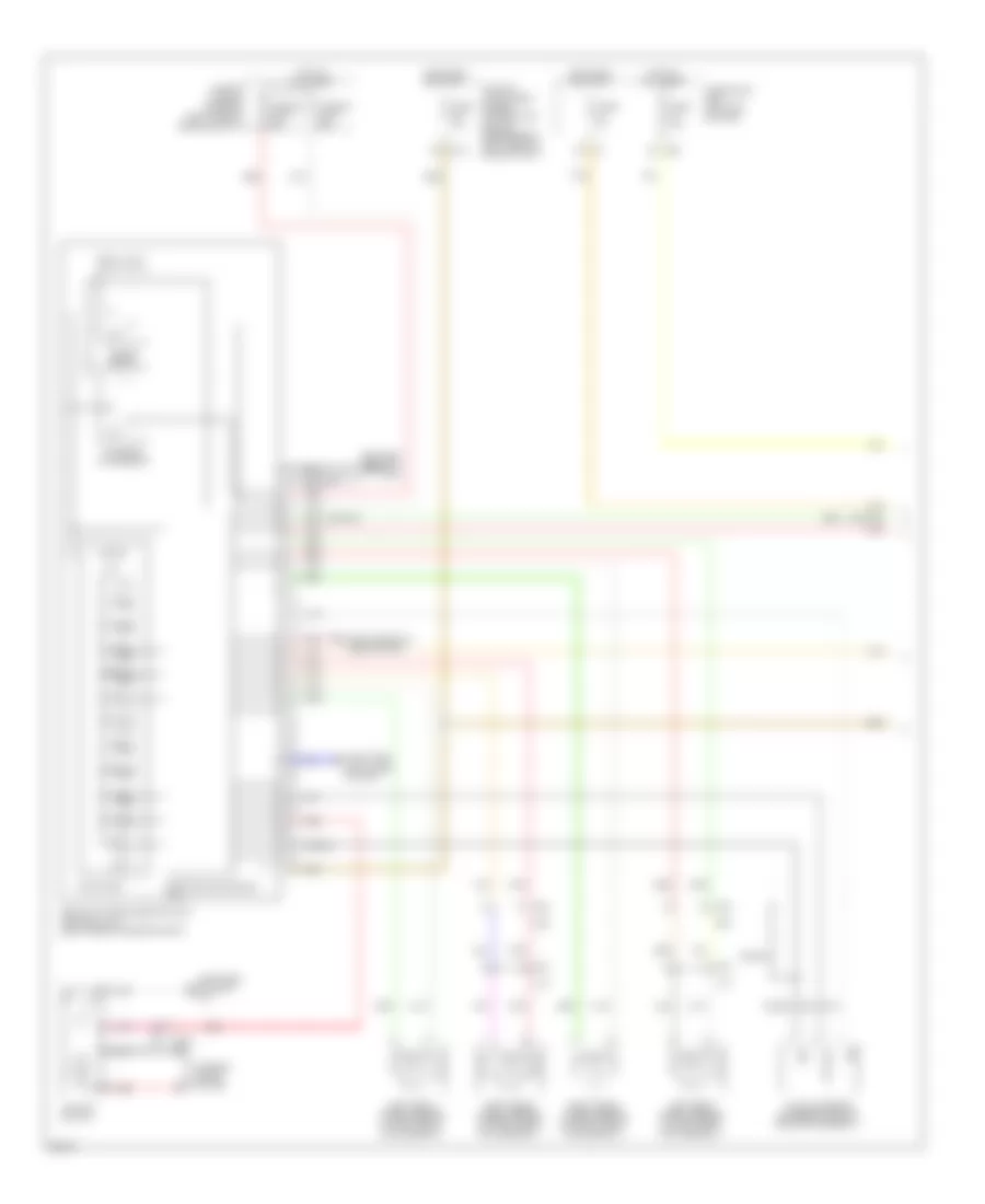
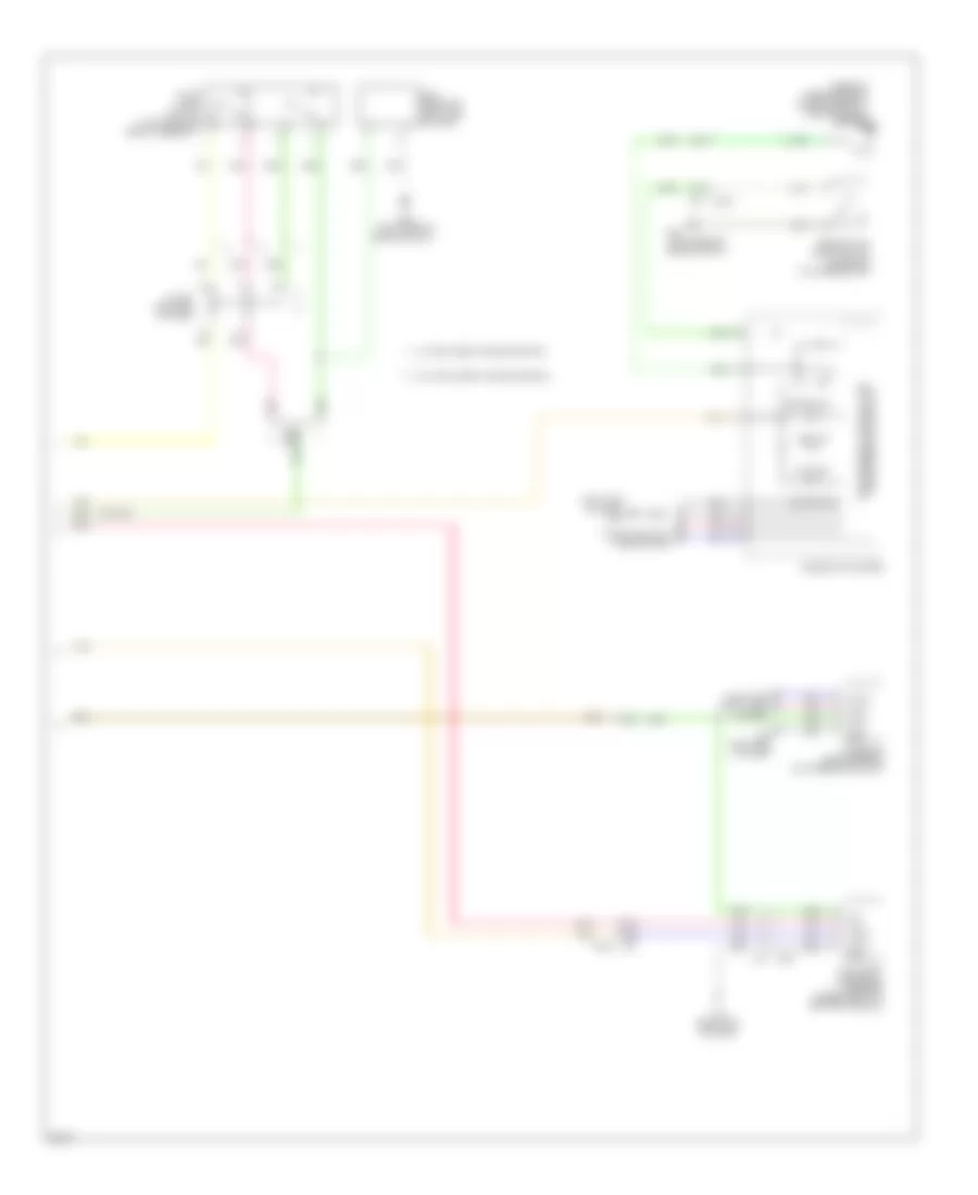
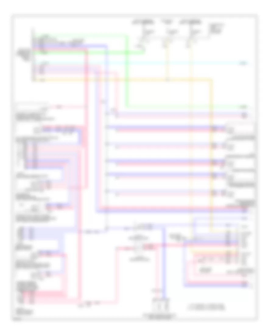
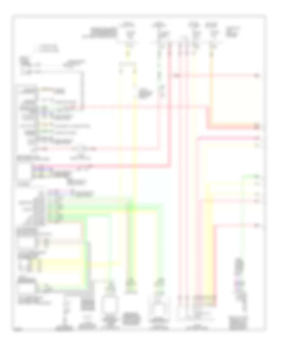
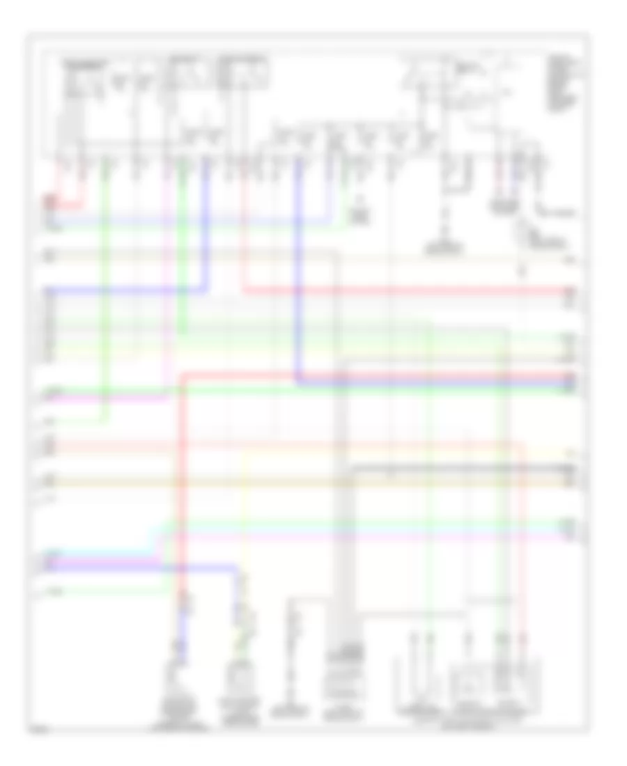
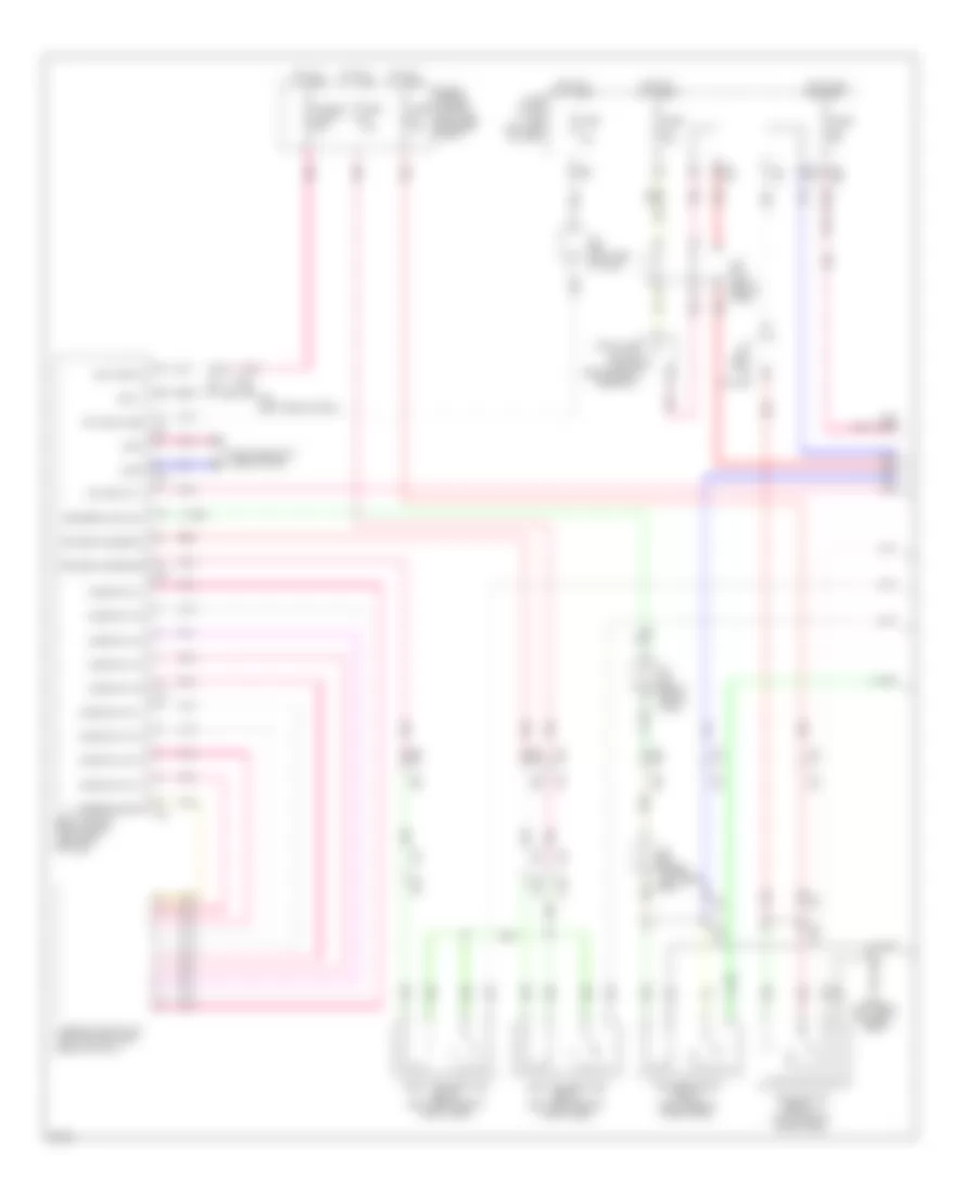
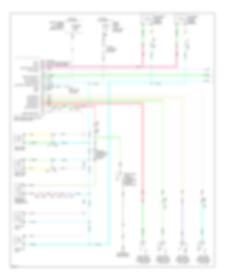
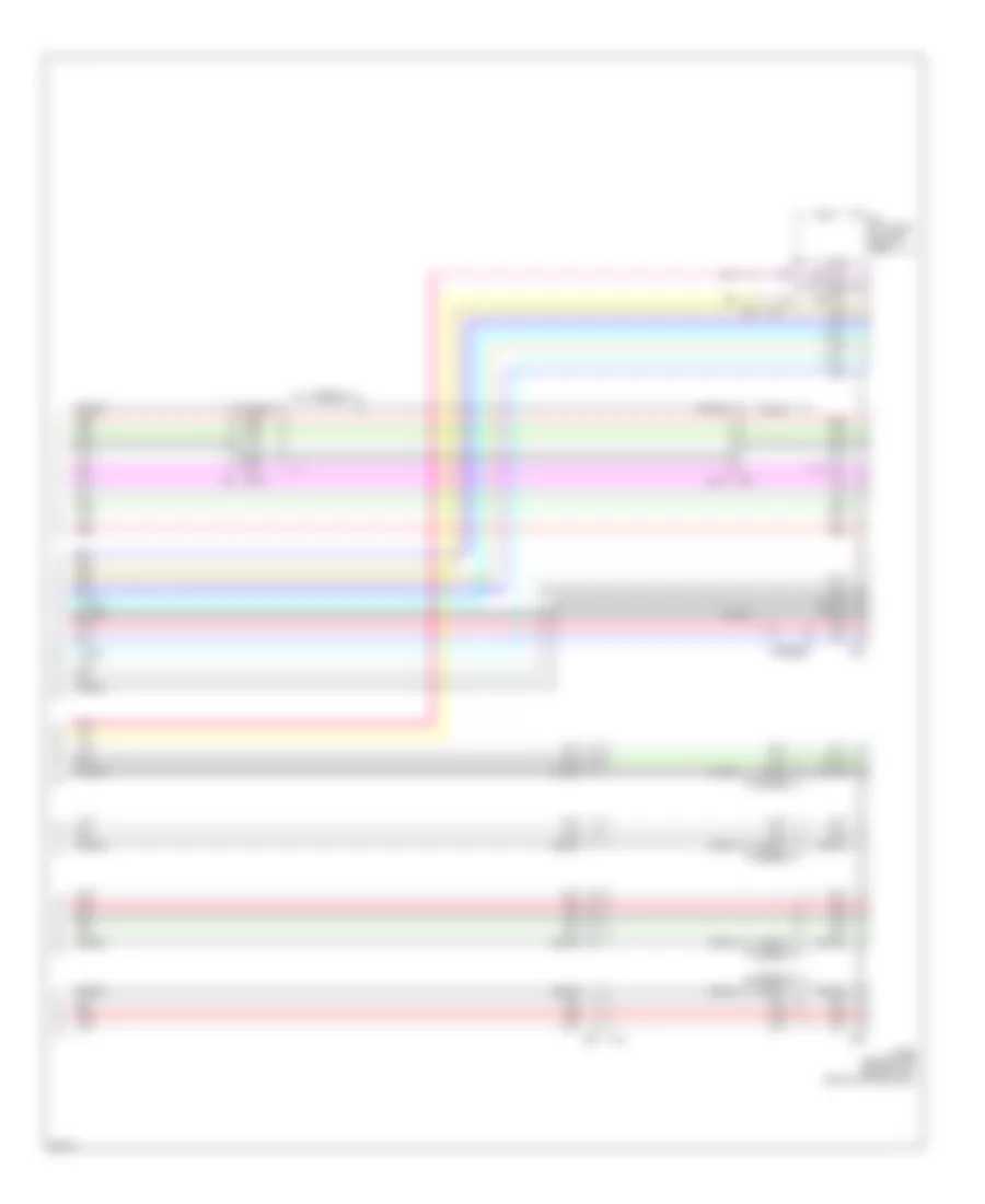
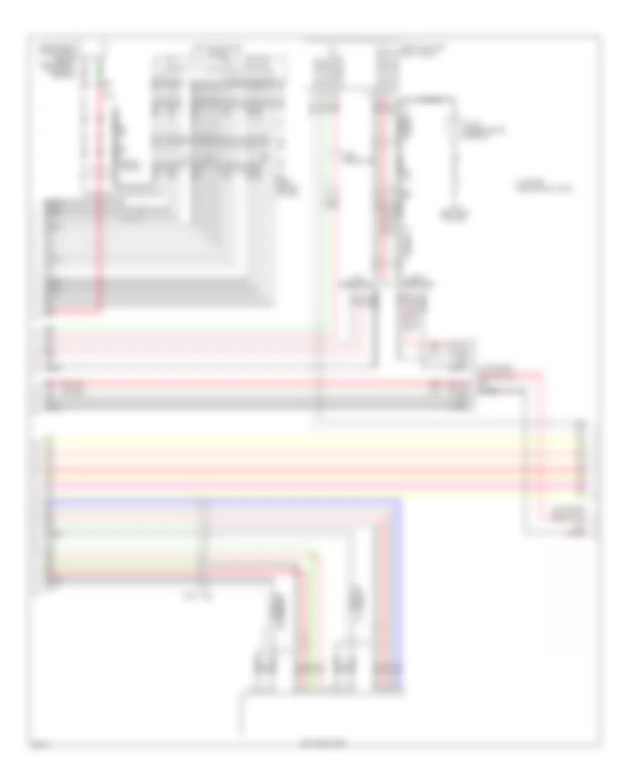
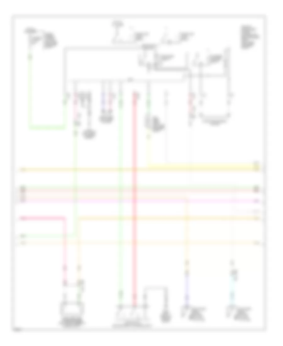
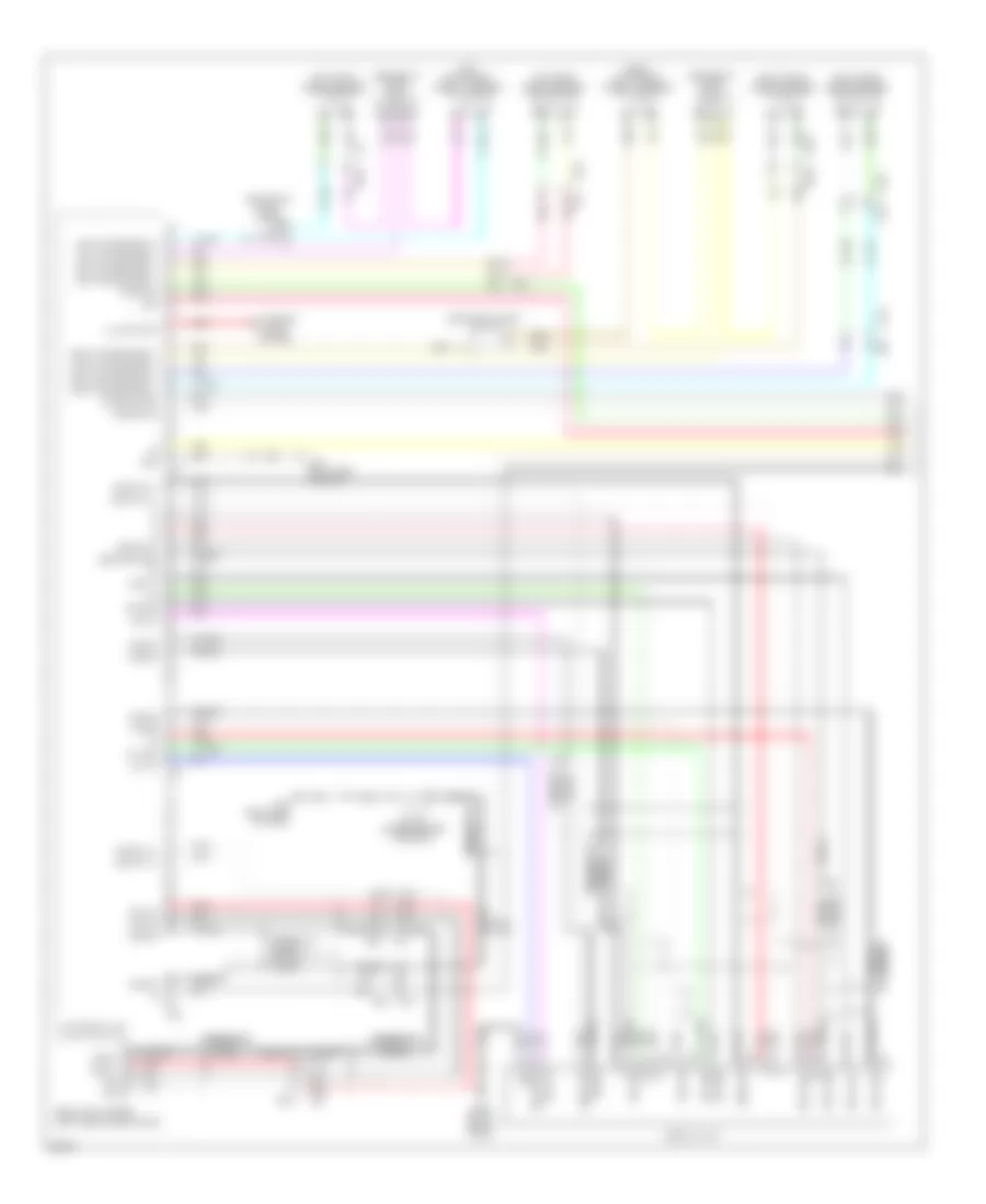
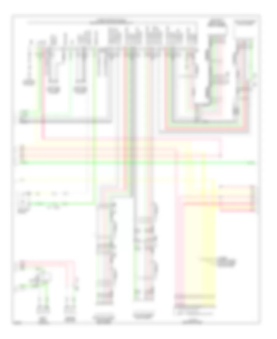
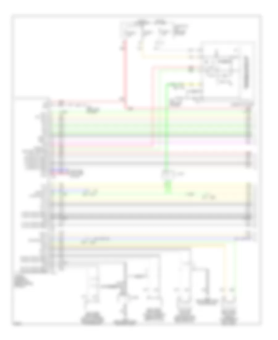
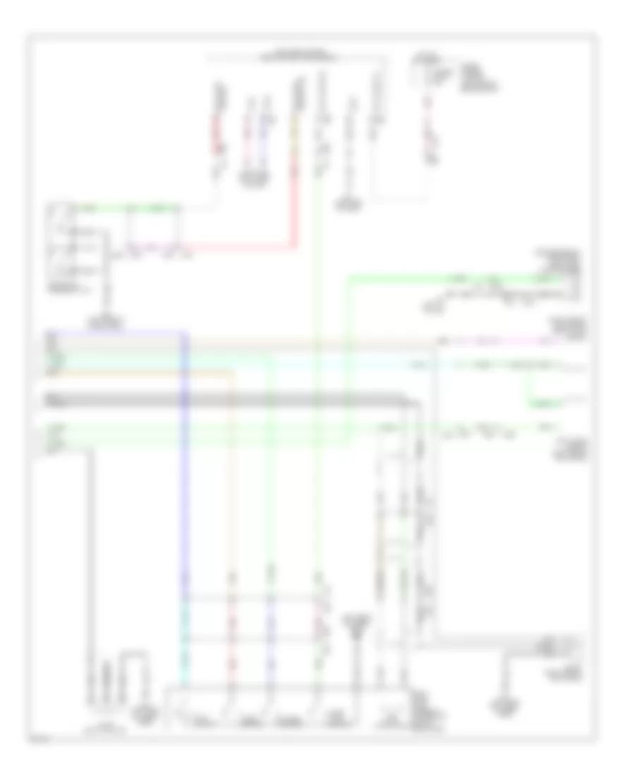
Automatic A/C Wiring Diagram (4 of 4) for Infiniti JX35 2013
List of elements for Automatic A/C Wiring Diagram (4 of 4) for Infiniti JX35 2013:
- (left front of engine compt) e216
- 63g
- A/c compressor (left front of engine)
- A/c relay
- Can-h
- Can-l
- Computer data lines system
- Cooling fan control module (on cooling fan motors assembly)
- Cooling fan motor 1 (behind left side of radiator)
- Cooling fan motor 2 (behind right side of radiator)
- Cooling fan relay (fuse & fusible link box)
- Cpu
- E119
- E121
- E15 (left rear of engine compt)
- E152
- E16
- E19
- E201 e40
- E218
- E225
- E245
- E246
- E9 (left rear of engine compt)
- Ecm (engine control module) (left front of engine compt)
- Engine coolant temperature sensor (rear of left cylinder bank)
- F19
- F32
- F33
- F51
- F52
- Fuse 10a
- Gnd
- Hot at all times
- Ignition relay 1
- Ipdm e/r (intelligent power distribution module engine room) (left rear of engine compt)
- J/c f04 (left front of engine compt)
- M31
- Pdpres
- Pdpres avcc 2
- Pdpres gnda
- Pnk
- Pwr
- Red
- Refrigerant pressure sensor (front left side of radiator)
- Sens gnd
- Sig
- Temp sens
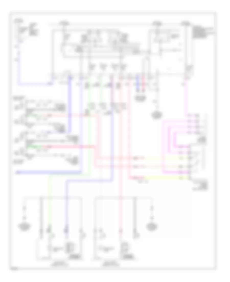
ANTI-LOCK BRAKES
Anti-lock Brakes Wiring Diagram (1 of 2) for Infiniti JX35 2013
List of elements for Anti-lock Brakes Wiring Diagram (1 of 2) for Infiniti JX35 2013:
- (left end of dash) e126
- (left side of dash) m57
- (or pnk)
- 56g
- 8p m4
- Abs actuator & electric unit (control unit) (right rear of engine compt)
- Abs/tcs/vdc control unit
- Actuator
- B13
- B40
- C13
- Computer data lines system
- E119
- E28 5m
- E34
- Fl in
- Fl out
- Fr in
- Fr out
- Fuse & fusible link box (left side of engine compt)
- Fuse 10a
- Fuse 5a
- Fuse block (j/b) (left end of dash)
- Fusible link i 50a
- Fusible link j 30a
- Gnd
- Hot at all times
- Hot in on or start
- Hsv 1
- Hsv 2
- Interior lights system
- Ipdm e/r (intelligent power distribution module engine room) (left rear of engine compt)
- Left front wheel sensor (on left front hub assembly)
- Left rear wheel sensor (on left rear hub assembly)
- M31 e152
- Motor
- Motor relay
- Pnk
- Red
- Relay unit
- Right front wheel sensor (on right front hub assembly)
- Right rear wheel sensor (on right rear hub assembly)
- Rl in
- Rl out
- Rr in
- Rr out
- Shield
- Sig
- Solenoid valve relay
- Tan
- U sv1
- U sv2
- Vacuum sensor (on brake vacuum booster assembly)
- Vcc(+5v)
- Vdc off switch
Anti-lock Brakes Wiring Diagram (2 of 2) for Infiniti JX35 2013
List of elements for Anti-lock Brakes Wiring Diagram (2 of 2) for Infiniti JX35 2013:
- (base of parking brake lever assembly) parking brake switch
- (left side of dash) m57
- (or pnk)
- 33g
- 34g
- 55g
- 57g
- 58g
- Abs ind
- Brake fluid level switch (on brake fluid reservoir)
- Brake ind
- Can-h
- Can-l
- Combination meter
- Computer data lines system
- E15 (left rear of engine compt)
- E152
- E152 m31
- Gnd
- Ign
- J/c e01 (left end of dash)
- M300
- M31
- M57 (left side of dash)
- M79 (right end of dash)
- Pnk
- Pwr
- Slip ind
- Steering angle sensor (on steering column)
- Stop lamp switch (top of brake pedal assembly)
- Tan
- Unified meter control unit (w/ information display)
- Vdc off ind
- Vdc resistor (left side of dash)
- W/ intelligent cruise control
- W/0 intelligent cruise control
- Yaw rate/ side/decel g sensor (under front of center console)
ANTI-THEFT
Forced Entry Wiring Diagram (1 of 4) for Infiniti JX35 2013
List of elements for Forced Entry Wiring Diagram (1 of 4) for Infiniti JX35 2013:
- (left side of dash) m57
- 10g
- 15a
- 16a
- 49a
- 50a
- Acc led
- As door ant a
- As door ant b
- As door sw
- As request sw
- B400
- B41
- B46
- B77
- Batt pwr f/l
- Batt saver output
- Between full stroke & n
- Bk door sw
- Body control module (bcm) (left side of dash)
- Buzzer out
- Can-h
- Can-l
- Computer data lines system
- Console inside key antenna (under rear of center console)
- Cpu
- D101
- D17
- D18
- D501
- D507
- D51
- D53
- D552
- Door key cylinder switch
- Door lock actuator
- Door lock dr/as/fl
- Door lock rr/rl
- Door unlock as
- Door unlock dr/fl
- Door unlock rr/rl
- Door unlock sensor
- Dr door ant a
- Dr door ant b
- Dr door lock status
- Dr door sw
- Dr request sw
- Driver side outside key antenna (driver's door)
- E152 m31
- Eng start sw
- Exterior lights system
- Fl flasher
- Fr flasher
- Full stroke
- Fuse & fusible link box (left side of engine compt)
- Fusible link o 40a
- Gnd
- Gnd 2
- Hazard sw
- Hot at all times
- Instrument center inside key (under center of dash)
- Interior lights system
- J/c m09 (right side of dash)
- Left front door lock assembly
- Lock
- Lock unlock
- Luggage room inside key antenna (center front of cargo area)
- M167
- M168
- M168 d3
- M18
- M19
- M20
- M202
- M217
- M257
- M40 b69
- M57 (left side of dash)
- M65
- M69
- M80
- M81
- M91
- Main power window & door lock/unlock switch
- Passenger side outside key antenna (passenger's front door)
- Pnk
- Pw lin/com
- Rear bumper outside key antenna (behind center of rear bumper)
- Red
- Rf nimoco
- Rl door sw
- Room ant 1 a
- Room ant 1 b
- Room ant 2 a
- Room ant 2 b
- Room ant 3 a
- Room ant 3 b
- Room lamp cont
- Rr bumper ant a
- Rr bumper ant b
- Rr door sw
- Tan
- Unlock
Forced Entry Wiring Diagram (2 of 4) for Infiniti JX35 2013
List of elements for Forced Entry Wiring Diagram (2 of 4) for Infiniti JX35 2013:
- (behind left rear quarterpanel) fuel lid door lock actuator
- (lower left side of back door) back door lock assembly
- 77a
- 78a
- Acc/on ind
- B139
- B161
- B19 (left rear of cargo area)
- B51
- B69
- Back door opener switch
- Cpu
- D101
- D102
- D110
- D151
- D201
- D301
- D507
- D552
- D91
- Door ajar switch
- Gnd
- Ill
- Interior lights system
- J/c m22 (center of dash)
- Left front outside handle assembly
- Left rear door lock actuator
- Lock
- M139 (right end of dash)
- M157
- M158
- M168 d3
- M40
- M57 (left side of dash)
- M61 (left side of dash)
- M79 (right end of dash)
- M91 d101
- Pnk
- Push button ignition switch
- Push switch
- Red
- Remote keyless entry receiver (right end of dash)
- Request switch
- Right front door lock actuator
- Right front outside handle assembly
- Right power window & door lock/unlock switch
- Right rear door lock actuator
- Tan
- Unlock
Forced Entry Wiring Diagram (3 of 4) for Infiniti JX35 2013
List of elements for Forced Entry Wiring Diagram (3 of 4) for Infiniti JX35 2013:
- 62g
- 64g
- 65a
- 66a
- 69g
- 70g
- Anti- theft diode (left side of engine compt)
- Computer data lines system
- Cpu
- E119
- E120
- E121
- E15 (left rear of engine compt)
- E152
- E213 (left front of engine compt)
- E218
- F17
- F24
- Fuse & fusible link box (left side of engine compt)
- Fusible link k 40a
- Headlamp high relay
- Headlamp low relay
- Headlights system
- Hood switch (center front of engine compt)
- Hot at all times
- Intelligent key warning buzzer (left rear corner of engine compt)
- Ipdm e/r (intelligent power distribution module engine room) (left rear of engine compt)
- Left front door switch (at left "b" pillar)
- Left rear door switch (at left "c" pillar)
- M31
- M31 e152
- M40 b69
- Pnk
- Red
- Starter control relay
- Starter relay
- Starting/charging system
- Tan
Forced Entry Wiring Diagram (4 of 4) for Infiniti JX35 2013
List of elements for Forced Entry Wiring Diagram (4 of 4) for Infiniti JX35 2013:
- (left end of dash) j/c e01
- 10r
- 13p
- Anti- theft horn
- Anti- theft horn relay (left front of engine compt)
- Audio dongle
- B41
- B46
- Body control module (bcm) (left side of dash)
- Brake sw fuse
- Brake sw lamp
- Buzzer
- Combination meter
- Computer data lines system
- D501
- Dongle unit (center of dash)
- E207
- E28
- Fuse & fusible link box (left side of engine compt)
- Fuse 10a
- Fuse 15a
- Fuse 5a
- Fuse block (j/b) (left end of dash)
- Horn relay (in left fuse & relay box)
- Horns system
- Hot at all times
- Hot in on or start
- J/c e05 (left side of engine compt)
- Key ind
- M18
- M19
- M20
- M57 (left side of dash)
- M61 (left side of dash)
- M68
- M69
- M84 b101
- Pnk
- Red
- Right front door switch (at right "b" pillar)
- Right rear door switch (at right "c" pillar)
- Rl door sw
- Security ind
- Starter relay out
- Stop lamp switch (top of brake pedal assembly)
- Tan
- Unified meter control unit (w/ information display)
Immobilizer Wiring Diagram for Infiniti JX35 2013
List of elements for Immobilizer Wiring Diagram for Infiniti JX35 2013:
- 10g
- 13p
- Batt pwr f/l
- Body control module (bcm) (left side of dash)
- Can-h
- Can-l
- Combination meter
- Computer data lines system
- E152 m31
- Fuse & fusible link box (left side of engine compt)
- Fuse 10a
- Fuse 5a
- Fuse block (j/b) (left end of dash)
- Fusible link o 40a
- Gnd 2
- Hot at all times
- Hot in on or start
- Immo start button ant a
- Immo start button ant b
- M18
- M19
- M57 (left side of dash)
- M80
- M81
- Nats antenna amp (left center of dash)
- Pnk
- Security ind
- Tan
- Unified meter control unit (w/ information display)
BODY CONTROL MODULES
Body Control Modules Wiring Diagram for Infiniti JX35 2013
List of elements for Body Control Modules Wiring Diagram for Infiniti JX35 2013:
- (left side of dash) m57
- (or pnk)
- 6n m3
- 6q b30
- 9p m4
- A/l pwr sply 5v
- A/l signal
- Acc led
- Acc rly out
- Air conditioning system
- Anti-theft system
- As door ant a
- As door ant b
- As door sw
- As request switch
- At device out
- Audio dongle
- Back bumper ant a
- Back bumper ant b
- Back door open sw
- Back door req sw
- Back door sw
- Bat bcm fuse
- Bat rear door
- Bat rear wiper fuse
- Batt front door
- Batt pwr f/l
- Battery saver out
- Bcm (body control module) (left side of dash)
- Blower fan rly out
- Brake sw fuse
- Brake sw lamp
- Buzzer out
- Can-h
- Can-l
- Combi sw in 1
- Combi sw in 2
- Combi sw in 3
- Combi sw in 4
- Combi sw in 5
- Combi sw out 1
- Combi sw out 2
- Combi sw out 3
- Combi sw out 4
- Combi sw out 5
- Computer data lines system
- Defogger system
- Door handle lamp
- Door lk dr/as/fl
- Door lk rr/rl
- Door locks & anti-theft systems
- Door locks system
- Door locks system trunk, tailgate, fuel doors system
- Door ulk dr/fl
- Door ulk rr/rl
- Door unlock as
- Dr door ant a
- Dr door ant b
- Dr door lk status
- Dr door sw
- Dr request switch
- Engine controls system
- Engine start switch
- Exterior lights system
- Fl flasher
- Fr flasher
- Fuse & fusible link box (left side of engine compt)
- Fuse 10a
- Fuse 15a
- Fuse 5a
- Fuse block (j/b) (left end of dash)
- Fusible link o 40a
- Gnd 1
- Gnd 2
- Gnd rf a/l
- Hazard switch
- Headlights system
- Headlights, interior lights & exterior lights systems
- High side start sw led
- Hot at all times
- I-key link signal
- Ign elec rly out 2
- Ign usm out 1
- Immo st butt ant a
- Immo st butt ant b
- Interior lights system
- Interior lights system door locks & anti-theft systems
- J/c m36 (left side of dash)
- Low side start sw led
- M18
- M19
- M20
- M57 (left side of dash)
- M79 (right end of dash)
- M80
- M81
- Mr output
- Navigation & sound systems
- Navigation & sound systems door locks & anti-theft systems interior lights system
- P/w pwr sply bat
- P/w pwr sply ign
- Pnk
- Power distribution system
- Power windows system
- Power windows, power tops & seats systems
- Push button ignition switch
- Push switch
- Pw lin/com
- R sensor k-line
- R wiper autostop sw
- Rear defogger rly out
- Rear wiper out
- Red
- Reverse lamp out
- Reverse signal
- Rf nimoco
- Rl door sw
- Rl flasher
- Room ant 1 a
- Room ant 1 b
- Room ant 2 a
- Room ant 2 b
- Room ant 3 a
- Room ant 3 b
- Room lamp cont
- Room lamp timer
- Rr door sw
- Rr flasher
- Security indicator
- Shift interlock system
- Shift lock sol out
- Shift n/p
- Shift p
- Shorting input
- Starter rly out
- Starting/charging system
- Step lamp cont
- Tan
- Trailer flasher rl
- Trailer flasher rr
- Trunk, tailgate, fuel doors system
- Wiper/washer system
COMPUTER DATA LINES
Computer Data Lines Wiring Diagram, with Memory with ICC (1 of 3) for Infiniti JX35 2013
List of elements for Computer Data Lines Wiring Diagram, with Memory with ICC (1 of 3) for Infiniti JX35 2013:
- (left side of dash) m57
- 35g
- 36g
- A/c auto amplifier (lower center of dash)
- Abs actuator & electric unit (control unit) (right rear of engine compt)
- Bcm (body control module) (left side of dash)
- Can-h
- Can-l
- Combination meter
- Cpu
- Cvt control w/ sport mode
- Cvt control w/o sport mode
- Data link
- Data link connector (lower left side of dash)
- E119
- E152
- E16
- E62
- Ecm (engine control module) (left front of engine compt)
- F32
- Fuse 25 10a
- Fuse 30 10a
- Fuse 31 5a
- Fuse block (j/b) (left end of dash)
- Hot at all times
- Hot w/ ignition relay 2 energized
- Ipdm e/r (intelligent power distribution module engine room) (left rear of engine compt)
- J/c e12 (left side of engine compt)
- J/c e14 (right rear of engine compt)
- J/c e15 (right rear of engine compt)
- J/c m17 (center of dash)
- J/c m18 (center of dash)
- K-line
- M19
- M24
- M31
- Occupant classification system control unit (under front passenger's seat)
- Pnk
- Power steering control module (lower right rear of engine compt)
- Red
- Steering angle sensor (on steering column)
- Tan
- Tcm (transmission control module) (left front of engine compt)
- Tcu (under rear of console)
Computer Data Lines Wiring Diagram, with Memory with ICC (2 of 3) for Infiniti JX35 2013
List of elements for Computer Data Lines Wiring Diagram, with Memory with ICC (2 of 3) for Infiniti JX35 2013:
- (left center of dash) j/c m56
- (left center of dash) j/c m57
- (under center console) around view monitor control unit
- 89a
- 90a
- A/c & av switch assembly
- Air bag diagnosis sensor unit (under center console)
- Av control unit (center of dash)
- B101
- B137
- B201
- B23
- B301
- B69
- Battery
- Bose w/ surround sound
- Bose w/o surround sound
- Can gateway (right center of dash)
- Can gnd
- Can-h
- Can-l
- Gnd
- Headrest display unit (driver seat)
- Headrest display unit (passenger seat)
- Ignition
- J/c m58 (right center (of dash)
- J/c m59
- M can gnd
- M can-1h
- M can-1l
- M can-h
- M can-l
- M124
- M163
- M36 b136
- M40
- M61 (left side of dash)
- M61 (right center of dash)
- M66 b6
- M84
- M96
- Mcan-h trm
- Mcan-l trm
- Pnk
- Shield
- Tan
- W/ bose audio system w/ rear entertainment system
- W/ bose audio system w/o rear entertainment system
Computer Data Lines Wiring Diagram, with Memory with ICC (3 of 3) for Infiniti JX35 2013
List of elements for Computer Data Lines Wiring Diagram, with Memory with ICC (3 of 3) for Infiniti JX35 2013:
- (base of right "b" pillar) lane camera unit
- (left center of dash) j/c m04
- (left rear of cargo area) j/c b12
- (left side of dash) sonar control unit
- (right rear of cargo area) j/c b13
- 40g
- 41g
- 80a
- 81a
- Accelerator pedal actuator (above accelerator pedal)
- Adas control unit (right rear of cargo area)
- Automatic back door control module (left rear of cargo area)
- Awd control unit (if equipped)
- B124
- B124 b32
- B132 (base of right "d" pillar)
- B32
- B400 b77
- B54 b200
- B69 m40
- Can-h
- Can-l
- Driver seat control unit (under driver's seat)
- E26 e209
- Icc sensor
- J/c b01 (left "d" pillar)
- J/c b08 (right "c" pillar)
- J/c b10 (base of left "b" pillar)
- J/c b11 (under third row seating)
- J/c b12 (left rear of cargo area)
- J/c b14 (center rear of cargo area)
- J/c b15 (center rear of cargo area)
- J/c e06 (near steering column)
- J/c e07 (near steering column)
- J/c m03
- J/c m27 (center of dash)
- J/c m28
- J/c m29
- Left side radar
- M31 e152
- M57 (left center of dash)
- Pnk
- Pre-crash seat belt control unit (driver side) (if equipped)
- R1 m1
- Right side radar (right rear corner of vehicle)
- Shield
- Tan
Computer Data Lines Wiring Diagram, with Memory without ICC (1 of 2) for Infiniti JX35 2013
List of elements for Computer Data Lines Wiring Diagram, with Memory without ICC (1 of 2) for Infiniti JX35 2013:
- (left side of dash)
- (left side of dash) m57
- (left side of dash) m61
- 35g
- 36g
- A/c auto amplifier (lower center of dash)
- Abs actuator & electric unit (control unit) (right rear of engine compt)
- Airbag diagnosis sensor unit (under center console)
- Battery
- Bcm (body control module) (left side of dash)
- Can gateway (right center of dash)
- Can-h
- Can-l
- Combination meter
- Cpu
- Cvt control w/ sport mode
- Cvt control w/o sport mode
- Data link
- Data link connector (lower left side of dash)
- E119
- E152
- E16
- E62
- Ecm (engine control module) (left front of engine compt)
- F32
- Fuse 25 10a
- Fuse 30 10a
- Fuse 31 5a
- Fuse block (j/b) (left end of dash)
- Gnd
- Hot at all times
- Hot w/ ignition relay 2 energized
- Ignition
- Ipdm e/r (intelligent power distribution module engine room) (left rear of engine compt)
- J/c e12 (left side of engine compt)
- J/c e14 (right rear of engine compt)
- J/c e15 (right rear of engine compt)
- J/c m17 (center of dash)
- J/c m18 (center of dash)
- K-line
- M19
- M24
- M31
- M61
- Occupant classification system control unit (under front passenger's seat)
- Pnk
- Power steering control module (lower right rear of engine compt)
- Steering angle sensor (on steering column)
- Tan
- Tcm (transmission control module) (left front of engine compt)
- Tcu (under rear of console)
Computer Data Lines Wiring Diagram, with Memory without ICC (2 of 2) for Infiniti JX35 2013
List of elements for Computer Data Lines Wiring Diagram, with Memory without ICC (2 of 2) for Infiniti JX35 2013:
- (left center of dash) j/c m56
- (left center of dash) j/c m57
- (left center of dash) m57
- (right end of dash)
- (under center console) around view monitor control unit
- 89a m40
- 90a
- A/c & av switch assembly
- Automatic back door control module (left rear of cargo area)
- Av control unit (center of dash)
- Awd control unit (if equipped)
- B101
- B124
- B136
- B137
- B200
- B201
- B23
- B301
- B32
- B54
- B69
- Bose w/ surround sound
- Bose w/o surround sound
- Can gnd
- Can-h
- Can-l
- Control unit
- Driver seat
- Headrest display unit (driver seat)
- Headrest display unit (passenger seat)
- J/c b09 (under third row seating)
- J/c b10 (left rear of cargo area)
- J/c b11 (under third row seating)
- J/c b12 (left rear of cargo area)
- J/c b14 (center rear of cargo area)
- J/c b15 (center rear of cargo area)
- J/c m27 (left end of dash)
- J/c m58 (right center of dash)
- J/c m59
- M can gnd
- M can-1h
- M can-1l
- M can-h
- M can-l
- M124
- M163
- M36
- M66
- M84
- M96
- Mcan-h trm
- Mcan-l trm
- Pnk
- Shield
- Sonar control unit (left side of dash)
- W/ bose audio system w/ rear entertainment system
- W/ bose audio system w/o rear entertainment system
Computer Data Lines Wiring Diagram, without Memory for Infiniti JX35 2013
List of elements for Computer Data Lines Wiring Diagram, without Memory for Infiniti JX35 2013:
- (below center of dash)
- (left center of dash) j/c m57
- (left side of dash) m57
- (on steering column)
- (right center of dash) j/c m58
- 35g
- 36g
- 89a
- 90a
- A/c & av switch assembly
- A/c auto amplifier (lower center of dash)
- Abs actuator & electric unit (control unit) (right rear of engine compt)
- Air bag diagnosis sensor unit
- Around view monitor control unit (under center console)
- Automatic back door control module (left rear of cargo area)
- Av control unit (center of dash)
- Awd control unit (if equipped)
- B101
- B136 m36
- B137
- B201
- B23
- B301
- B32 b124
- B69
- Bcm (body control module) (left side of dash)
- Bose w/ surround sound
- Bose w/o surround sound
- Can h
- Can l
- Can-h
- Can-l
- Combination meter
- Cpu
- Cvt control w/ sport mode
- Cvt control w/o sport mode
- Data link
- Data link connector (lower left side of dash)
- E119
- E152
- E16
- E62
- Ecm (engine control module) (left front of engine compt)
- F32
- Fuse 25 10a
- Fuse 30 10a
- Fuse block (j/b) (left end of dash)
- Headrest display unit (driver seat)
- Headrest display unit (passenger seat)
- Hot at all times
- Hot w/ ignition relay 2 energized
- Ipdm e/r (intelligent power distribution module engine room) (left rear of engine compt)
- J/c b09 (base of left "b" pillar)
- J/c b10 (base of left "b" pillar)
- J/c b11 (under third row seating)
- J/c b12 (left rear of cargo area)
- J/c b14 (center rear of cargo area)
- J/c b15 (center rear of cargo area)
- J/c e12 (left side of engine compt)
- J/c e14 (right rear of engine compt)
- J/c e15 (right rear of engine compt)
- J/c m17 (center of dash)
- J/c m18 (center of dash)
- J/c m56 (left center of dash)
- J/c m59
- K-line
- M can gnd
- M can-1h
- M can-1l
- M can-h
- M can-l
- M124
- M163
- M19
- M24
- M31
- M40
- M42
- M66 b6
- M84
- M96
- Mcan-h trm
- Mcan-l trm
- Nca
- Occupant classification system control unit (under front passenger's seat)
- Pnk
- Power steering control module (lower right rear of engine compt)
- Red
- Shield
- Steering angle sensor
- Tan
- Tcm (transmission control module) (left front of engine compt)
- W/ bose audio system w/ rear entertainment system
- W/ bose audio system w/o rear entertainment system
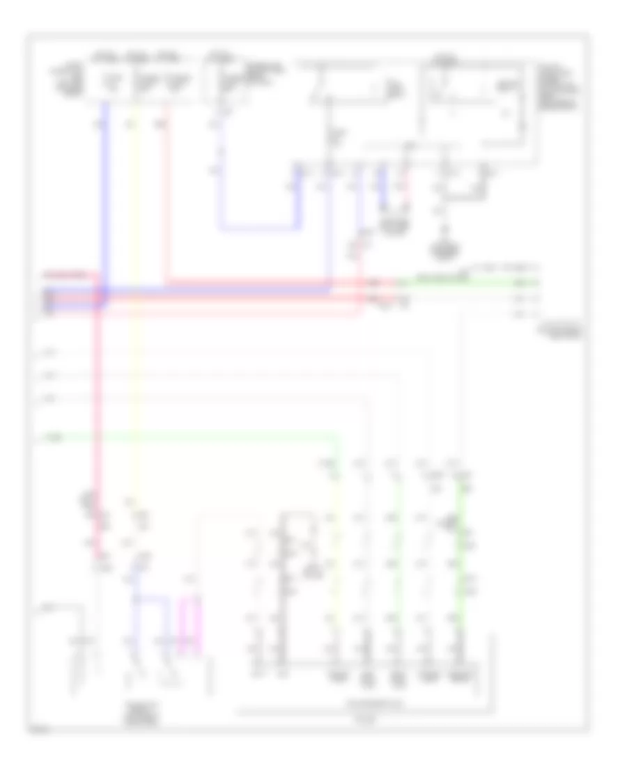
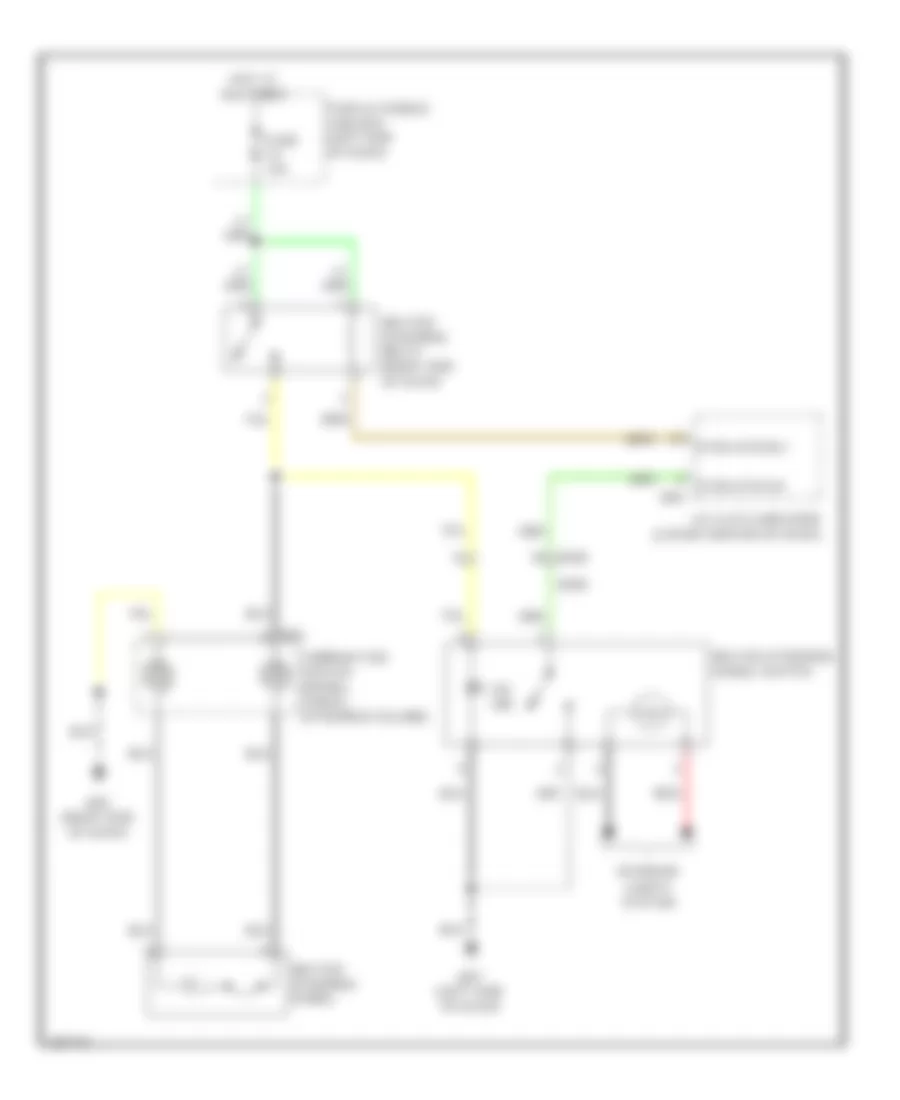
COOLING FAN
Cooling Fan Wiring Diagram for Infiniti JX35 2013
List of elements for Cooling Fan Wiring Diagram for Infiniti JX35 2013:
- (left front of engine compt) e216
- 63g
- A/c relay
- Air conditioning system
- Bcm (body control module) (left side of dash)
- Can-h
- Can-l
- Computer data lines system
- Cooling fan control module (on cooling fan motors assembly)
- Cooling fan motor 1 (behind left side of radiator)
- Cooling fan motor 2 (behind right side of radiator)
- Cooling fan relay (fuse & fusible link box)
- Cpu
- E119
- E121
- E15 (left rear of engine compt)
- E152
- E16
- E201 e40
- E218
- E225
- E245
- E246
- E9 (left rear of engine compt)
- Ecm (engine control module) (left front of engine compt)
- Engine coolant temperature sensor (rear of left cylinder bank)
- F19
- F32
- F51
- F52
- Fuse 10a
- Fusible link box (battery) (near battery)
- Fusible link h 60a
- Gnd
- Hot at all times
- Ignition relay 1
- Ipdm e/r (intelligent power distribution module engine room) (left rear of engine compt)
- J/c f04 (left front of engine compt)
- M19 out 1 ign usm
- M31
- Pdpres
- Pdpres avcc 2
- Pdpres gnda
- Pnk
- Pwr
- Red
- Refrigerant pressure sensor (front left side of radiator)
- Sens gnd
- Sig
- Temp sens
CRUISE CONTROL
Cruise Control Wiring Diagram (1 of 2) for Infiniti JX35 2013
List of elements for Cruise Control Wiring Diagram (1 of 2) for Infiniti JX35 2013:
- 80g
- 81g
- Accelerator pedal position sensor (top of accelerator pedal assembly)
- App sens 1
- App sens 2
- Ascd steering sw
- Can comm line can-h
- Can comm line can-l
- Computer data lines system
- E121
- E152
- E16
- E19 f33
- E28
- E9 (left rear of engine compt)
- Ecm gnd
- Engine control module (ecm) (left front of engine compt)
- F19
- F24
- F51
- Fuse 10a
- Fuse block (j/b) (left end of dash)
- Hot at all times
- Hot in on or start
- Hot w/ ign relay 1 energized
- Ipdm e/r (intelligent power distribution module engine room) (left rear of engine compt)
- J/c e01 (left end of dash)
- M31
- Mtr pwr sply
- Mtr rly
- Pnk
- Pwr sply
- Red
- Sens gnd
- Sens gnd (tps)
- Sens gnd(ascd steering sw)
- Sens pwr sply
- Sens pwr sply (tps)
- Sensor 1
- Sensor 2
- Stop lamp sw
- Stop lamp switch (top of brake pedal assembly)
- Throttle control motor relay
- Throttle ctrl mtr (cls)
- Throttle ctrl mtr (opn)
- Throttle posi sens 1
- Throttle posi sens 2
- W/ sport mode
- W/o sport mode
Cruise Control Wiring Diagram (2 of 2) for Infiniti JX35 2013
List of elements for Cruise Control Wiring Diagram (2 of 2) for Infiniti JX35 2013:
- (left rear of engine compt)
- (on throttle body) electric throttle control actuator
- (w/ information
- Accelerate/ resume switch
- Ascd steering switch
- Can h
- Can l
- Cancel switch
- Coast/ set switch
- Combination meter
- Combination switch (spiral cable) (steering column)
- Computer data lines system
- Control unit
- Cvt unit (w/ sport mode)
- Display)
- E15 (left rear of engine compt)
- E19
- F33
- Fuse 5a
- Fuse block (j/b) (left end of dash)
- Hot in on or start
- Input spd sens
- Input speed sensor (w/o sport mode) (left side of transmission)
- J/c f01 (left front of engine compt)
- J/c f02 (left front of engine compt)
- J/c f03 (left front of engine compt)
- M149
- M30
- M57 (left side of dash)
- Main (on/ off) switch
- Output spd sens
- Output speed sensor (w/o sport mode) (on transaxle)
- Pnk
- Pri spd sens
- Primary spd sens
- Primary speed sensor
- Primary speed sensor (w/o sport mode) (on transaxle)
- Red
- Secondary spd sens
- Secondary speed sensor (w/ sport mode) (right side of transmission)
- Sens gnd
- Sens pwr
- Sensor 1
- Sensor 2
- Shield
- Tan
- Tcm (transmission control module) (left front of engine compt)
- Throttle control motor
- Throttle position sensor
- Unified meter
- Vign
Intelligent Cruise Control Wiring Diagram (1 of 2) for Infiniti JX35 2013
List of elements for Intelligent Cruise Control Wiring Diagram (1 of 2) for Infiniti JX35 2013:
- (base of right "d" pillar) b132
- (right "c" pillar) j/c b08
- Abs actuator & electric unit (control unit) (right rear of engine compt)
- Adas control unit (right rear of cargo area)
- B101
- B136
- Bcp off sw
- Brake hold rly drv sig gnd
- Can h
- Can l
- Can-h
- Can-l
- Computer data lines system
- Cvt unit (w/ sport mode)
- Data lines computer
- E15 (left rear of engine compt)
- E19
- E207
- E214 (right front of engine compt)
- E28
- F19
- F33
- Fuse 10a
- Fuse 30 10a
- Fuse 5a
- Fuse block (j/b) (left end of dash)
- Hot at all times
- Hot in on or start
- Icc sensor
- Ign
- Input spd sens
- Input speed sensor (w/o sport mode) (left side of transmission)
- Instrument cluster system
- Ipdm e/r (intelligent power distribution module engine room) (left rear of engine compt)
- Its comm-h
- Its comm-l
- J/c b08 (right "c" pillar)
- J/c e01 (left end of dash)
- J/c f02 (left front of engine compt)
- J/c f03 (left front of engine compt)
- M36
- M84
- Output spd sens
- Output speed sensor (w/o sport mode) (on transaxle)
- Pnk
- Pri spd sens
- Primary spd sens
- Primary speed sensor
- Primary speed sensor (w/ sport mode) (on transaxle)
- Red
- Secondary spd sens
- Secondary speed sensor (w/ sport mode) (right side of transmission)
- Sens gnd
- Sens pwr
- Stop lamp sw
- System
- Tan
- Tcm (transmission control module) (left front of engine compt)
- W/ sport mode
- W/o sport mode
- Warning buzzer
- Warning sys on ind
- Warning systems
- Warning systems sw
Intelligent Cruise Control Wiring Diagram (2 of 2) for Infiniti JX35 2013
List of elements for Intelligent Cruise Control Wiring Diagram (2 of 2) for Infiniti JX35 2013:
- (on/off) main
- 39g
- 80g
- 81g
- Accelerator pedal actuator (above accelerator pedal)
- Accelerator pedal position sensor (top of accelerator pedal assembly)
- App sens 1
- App sens 2
- Ascd steering sw
- Brake
- Combination meter
- Combination switch (spiral cable) (steering column)
- Comm line can-h
- Comm line can-l sens gnd(ascd steering sw)
- Computer data lines system
- E15 (left rear of engine compt)
- E152
- E16
- E9 (left rear of engine compt)
- Engine control module (ecm) (left front of engine compt)
- Fuse 10a
- Fusible link box (battery) (near battery)
- Gnd
- Hot at all times
- Icc brake hold relay (in fuse & relay box (rh))
- Icc brake switch (near steering column)
- Icc steering switch
- J/c e05 (left side of engine compt)
- M149
- M30
- M31
- M57 (left side of dash)
- Nca
- Pnk
- Red
- Sens gnd
- Sens pwr sply
- Sensor 1
- Sensor 2
- Shield
- Stop lamp switch (top of brake pedal assembly)
- Switch accelerate resume/
- Switch assistance driver dynamic
- Switch cancel
- Switch coast set/
- Switch distance
- Tan
- Unified meter control unit (w/ information display)
DEFOGGERS
Defoggers Wiring Diagram for Infiniti JX35 2013
List of elements for Defoggers Wiring Diagram for Infiniti JX35 2013:
- 10g m31
- 13r m68
- 5p m4
- 5t b29
- 6n m3
- 6p m4
- Ac & av switch assembly
- Av control unit (center of dash)
- B47
- Bat bcm fuse
- Bat pwr f/l
- Body control module (bcm) (left side of dash)
- Can h
- Can l
- Computer data lines system
- D101
- D102
- D502
- D508
- D509
- D510
- D513 (left side of back door)
- D525
- E13 1s
- E152
- E30
- Fuse & fusible link box (left side of engine compt)
- Fuse 10a
- Fuse 15a
- Fuse block (j/b) (left end of dash)
- Fusible link box (battery) (near battery)
- Fusible link f 100a
- Fusible link o 40a
- Gnd 2
- Hot at all times
- Ign elec rly out 2
- Ignition relay 2
- J/c m36 (left side of dash)
- Left door mirror
- M can-h
- M can-l
- M124
- M139 (right end of dash)
- M158
- M167
- M168
- M19
- M4 3p
- M42
- M57 (left side of dash)
- M81
- M91
- Pnk
- Rear window defogger
- Rear window defogger condenser (left side of back door)
- Rear window defogger relay
- Red
- Right door mirror
- Rr defg rly out
- Tan
- W/ bose audio system
- W/ memory
- W/o bose audio system
- W/o memory
ELECTRONIC POWER STEERING
Electronic Power Steering Wiring Diagram for Infiniti JX35 2013
List of elements for Electronic Power Steering Wiring Diagram for Infiniti JX35 2013:
- (lower right rear of engine compt) power steering control module
- Bat
- Can-h
- Can-l
- Combination meter
- Computer data lines system
- E119
- E16
- E61 (right rear of engine compt)
- E62
- E63
- Engine control module (ecm) (left front of engine compt)
- Eps ind
- Fuse 10a
- Fuse 5a
- Fuse block j/b (left end of dash)
- Fusible link box (battery) (near battery)
- Fusible link d 100a
- Gnd
- Hot at all times
- Hot w/ ignition relay 1 energized
- Hot w/ ignition relay 2 energized
- Ign
- Ipdm e/r (intelligent power distribution module engine room) (left rear of engine compt)
- M24
- M57 (left side of dash)
- Pnk
- Steering angle sensor (on steering column)
- Tan
- Unified meter control unit (w/ information display)
ENGINE PERFORMANCE
3.5L
3.5L, Engine Performance Wiring Diagram (1 of 6) for Infiniti JX35 2013
List of elements for 3.5L, Engine Performance Wiring Diagram (1 of 6) for Infiniti JX35 2013:
- (left rear of engine) condenser 1
- (top of left cylinder bank) ignition coil 2 (w/ power transistor)
- (top of left cylinder bank) ignition coil 4 (w/ power transistor)
- (top of left cylinder bank) ignition coil 6 (w/ power transistor)
- (top of right cylinder bank) ignition coil 1 (w/ power transistor)
- (top of right cylinder bank) ignition coil 3 (w/ power transistor)
- (top of right cylinder bank) ignition coil 5 (w/ power transistor)
- A/f sens 1 htr(bank 1)
- A/f sens 1 htr(bank 2)
- E19
- E9 (left rear of engine compt)
- Ecm ground
- Ecm rly (self shut-off)
- Electronic ctrl eng sol vlv
- Eng oil press sens
- Engine control module (ecm) (left front of engine compt)
- F33
- F51
- F52
- F60 (left front of engine)
- Fuel inj 1
- Fuel injector 2
- Fuel injector 3
- Fuel injector 4
- Fuel injector 4 (left side of intake manifold)
- Fuel injector 5
- Fuel injector 6
- Fuel pump rely
- Heated o2 sens 2 htr 1(bank 1)
- Heated o2 sens 2 htr 2(bank 2) evap canister purge vol ctrl sol valve
- Heated oxygen sens 2 (bank 1)
- Heated oxygen sens 2 (bank 2)
- Heated oxygen sensor 2 (bank 1) (in exhaust, downstream of right three way catalyst)
- Heated oxygen sensor 2 (bank 2) (in exhaust, downstream of left three way catalyst)
- Ign sig no.1
- Ign sig no.2
- Ign sig no.3
- Ign sig no.4
- Ign sig no.5
- Ign sig no.6
- Intake vlv timing ctrl sol vlv (bank 2)
- J/c f04 (left front of engine compt)
- Loop wire
- Nca
- Plug spark
- Pwr sply for ecm
- Red
- Refrigerant press sens
- Sens gnd
- Sens ground
- Sens pwr sply
- Sens pwr sply intake vlv timing ctrl sol vlv (bank 1)
- Spark plug
- Throttle ctrl mtr (close)
- Throttle ctrl mtr (open)
- Throttle ctrl mtr pwr sply
- Throttle ctrl mtr rly
- Throttle position sens 1
- Throttle position sens 2
- Vias ctrl sol valve 1
- Vias ctrl sol valve 2
3.5L, Engine Performance Wiring Diagram (2 of 6) for Infiniti JX35 2013
List of elements for 3.5L, Engine Performance Wiring Diagram (2 of 6) for Infiniti JX35 2013:
- (left front of engine compt) j/c f04
- (left side of engine compt) j/c f07
- (left side of engine compt) j/c f08
- Fuel injector 1
- Fuel injector 2 (left side of intake manifold)
- Fuel injector 6 (left side of intake manifold)
- Fusible link box (battery) (near battery)
- Fusible link e 80a
- Hot at all times
- Intake valve timing control solenoid valve (bank 1) (front of right cylinder bank)
- Intake valve timing control solenoid valve (bank 2) (front of left cylinder bank)
- Red
- Vias control solenoid valve 1 (top of right cylinder bank)
- Vias control solenoid valve 2 (top of right cylinder bank)
3.5L, Engine Performance Wiring Diagram (3 of 6) for Infiniti JX35 2013
List of elements for 3.5L, Engine Performance Wiring Diagram (3 of 6) for Infiniti JX35 2013:
- Computer data lines system
- Cooling fans system
- Cpu
- E118
- E119
- E121
- E15 (left rear of engine compt)
- E2 f32
- E34 b40
- E9 (left rear of engine compt)
- Ecm relay
- Electric throttle control actuator (on throttle body)
- Electronic controlled engine mount control solenoid valve (left front of engine)
- Evap canister vent control valve (under spare tire housing)
- F19
- F24
- F32 e2
- F33 e19
- Fuel pump relay
- Fuse 10a
- Fuse 15a
- Ignition relay 1
- Ipdm e/r (intelligent power distribution module engine room) (left rear of engine compt)
- J/c e05 (left side of engine compt)
- J/c f01 (left front of engine compt)
- Pnk
- Red
- Sensor 1
- Sensor 2
- Shield
- Throttle control motor
- Throttle control motor relay
- Throttle position sensor
3.5L, Engine Performance Wiring Diagram (4 of 6) for Infiniti JX35 2013
List of elements for 3.5L, Engine Performance Wiring Diagram (4 of 6) for Infiniti JX35 2013:
- (base of left " b" pillar) condenser 2
- (in fuel tank) fuel level sensor unit & fuel pump
- (left front of engine compt) j/c f04
- (on left exhaust manifold) air fuel ratio (a/f) sensor 1 (bank 2)
- (on right exhaust manifold) air fuel ratio (a/f) sensor 1 (bank 1)
- (right rear of engine) evap canister purge volume control solenoid valve
- B40 e34
- B43 e33
- B7 (left "c" pillar)
- Camshaft position sensor (phase) (bank 1) (rear of right cylinder bank)
- Camshaft position sensor (phase) (bank 2) (rear of left cylinder bank)
- Can-h
- Can-l
- Computer data lines system
- Crankshaft position sensor (pos) (lower left rear of engine)
- E119
- F15
- F26 f201
- F32 e2
- F33 e19
- Fuel level sensor
- Fuel pump
- Fuel tank temperature sensor
- Instrument cluster system
- Ipdm e/r (intelligent power distribution e218 module engine room) (left rear of engine compt)
- J/c b01 (left "d" pillar)
- Knock sensor (bank 1) (under intake manifold, on right cylinder bank)
- Knock sensor (bank 2) (under intake manifold, on left cylinder bank)
- Pnk
- Red
- Refrigerant pressure sensor (front left side of radiator)
- Shield
- Strt rly
- Transmission control module (tcm) (left front of engine compt)
- W/ sport mode
- W/o sport mode
3.5L, Engine Performance Wiring Diagram (5 of 6) for Infiniti JX35 2013
List of elements for 3.5L, Engine Performance Wiring Diagram (5 of 6) for Infiniti JX35 2013:
- (on air cleaner box) mass air flow sensor
- (top of brake pedal assembly) stop lamp switch
- 13p
- Bat
- Can-h
- Can-l
- Combination meter
- Computer data lines system
- E28
- F33 e19
- Fuse 10a
- Fuse 5a
- Fuse block (j/b) (left end of dash)
- Gnd 1
- Gnd 2
- Hot at all times
- Hot w/ ignition relay 2 energized
- Ign
- Intake air temperature sensor
- M24
- M57 (left side of dash)
- Malfunction indicator lamp (mil)
- Pnk
- Red
- Shield
- Tan
- Transmission range switch (w/o sport mode) (left side of transmission)
- Unified meter control unit (w/ information display)
3.5L, Engine Performance Wiring Diagram (6 of 6) for Infiniti JX35 2013
List of elements for 3.5L, Engine Performance Wiring Diagram (6 of 6) for Infiniti JX35 2013:
- (left end of dash) j/c e01
- (left front of engine compt) j/c f04
- (lower right front of engine) engine oil temperature sensor
- (on battery) battery current sensor
- (or red)
- (rear of left cylinder bank) engine coolant temperature sensor
- A/f sens 1 (bank 1)
- A/f sens 1 (bank 2)
- Accelerator pdl pos sens 1
- Accelerator pdl pos sens 2
- Accelerator pedal position sensor (top of accelerator pedal assembly)
- Ascd steering sw
- Batt current sens
- Batt temp sens
- Brake pedal position switch (top of brake pedal assembly)
- Can-h
- Can-l
- Computer data lines system
- Crankshaft pos sens (pos)
- Cruise control system
- Data link connector
- E16
- E34 b40
- E9 (left rear of engine compt)
- Ecm gnd
- Eng coolant temp sens
- Eng oil temp sens
- Engine control module (ecm) (left front of engine compt)
- Engine oil pressure sensor (lower front of engine)
- Evap canister vent ctrl vlv
- Evap control system pressure sensor (under spare tire housing)
- F32
- F52
- Fuel tank temp sens
- Ign sw
- Intake air temp sens
- J/c e01 (left end of dash)
- J/c e05 (left side of engine compt)
- Knock sens (bank 1)
- Knock sens (bank 2)
- Mass air flow sens
- Pnk
- Pnp sig
- Pwr sply for ecm
- Red
- Sens gnd
- Sens gnd ascd steering sw/ icc steering sw evap ctrl sys press sens
- Sens gnd camshaft pos sens (phase) (bank 2) camshaft pos sens (phase) (bank 1)
- Sens pwr sig
- Sens pwr sply
- Sensor 1
- Sensor 2
- Shield
- Stp lp sw
- Tan
- W/ intelligent cruise control
- W/o intelligent cruise control
EXTERIOR LIGHTS
Backup Lamps Wiring Diagram for Infiniti JX35 2013
List of elements for Backup Lamps Wiring Diagram for Infiniti JX35 2013:
- (center of dash)
- (left center of dash) m57
- 79a
- Av control unit
- B19 (left rear of cargo area)
- B246
- B45
- B46
- B69
- Bat bcm fuse
- Bat pwr f/l
- Body control module (bcm) (left side of dash)
- Can-h
- Can-l
- Computer data
- Computer data lines system
- D501
- D507
- D552
- F24
- Fuse & fusible link box (left side of engine compt)
- Fuse 1 10a
- Fuse 48 10a
- Fuse block (j/b) (left end of dash)
- Fusible link o 40a
- Gnd1
- Hot at all times
- Hot w/ ignition relay 1 energized
- Ipdm e/r (intelligent power distribution module engine room) (left rear of engine compt)
- J/c b20 (under left rear seat)
- J/c m21 (right end of dash)
- J/c m36 (right end of dash)
- Left backup lamp
- Lines system
- M124
- M163
- M19
- M20
- M40
- M80
- M81
- Pnk
- R p
- R range sw
- Red
- Rev lmp out
- Rev sig
- Right backup lamp
- Trailer backup relay (left rear of cargo area)
- Transmission control module (tcm) (left front of engine compt)
- Transmission range switch (left side of transmission)
- W/ surround sound
- W/o surround sound
Exterior Lamps Wiring Diagram (1 of 2) for Infiniti JX35 2013
List of elements for Exterior Lamps Wiring Diagram (1 of 2) for Infiniti JX35 2013:
- 11a
- 12a
- 19g
- 20g
- 63g
- A/c & av switch assembly
- As door sw
- B19 (left rear of cargo area)
- B232
- B233
- B29
- B30
- B400
- B46
- B47
- B69
- B77
- Bat bcm fuse
- Bat pwr f/l
- Body control module (bcm) (left side of dash)
- Can-h
- Can-l
- Combi sw in 1
- Combi sw in 2
- Combi sw in 3
- Combi sw in 4
- Combi sw in 5
- Combi sw out 1
- Combi sw out 2
- Combi sw out 3
- Combi sw out 4
- Combi sw out 5
- Combination switch (lighting & turn signal switch)
- Computer data lines system
- D501
- D502
- Dr door sw
- E152
- E209
- E213 (left front of engine compt)
- E214 (right front of engine compt)
- E215 (right front of engine compt)
- E232
- E233
- E234
- E235
- E239
- E240
- E241
- E26
- E28
- E325
- E326
- E329
- Fl flasher
- Fr flasher
- Fuse & fusible link box (left side of engine compt)
- Fuse 1 10a
- Fuse 10a
- Fuse block (j/b) (left end of dash)
- Fusible link g 30a
- Fusible link o 40a
- Gnd 1
- Hazard sw
- High mounted stop lamp
- Hot at all times
- Ign usm out 1
- Interior lights system
- J/c e01 (left end of dash)
- J/c m36 (left side of dash)
- Left front combination lamp
- M18
- M19
- M20
- M28
- M31
- M40
- M57 (left side of dash)
- M80
- M81
- Parking
- Pnk
- Red
- Right front combination lamp
- Rl door sw
- Rl flasher
- Rr door sw
- Rr flasher
- Side marker
- Stop lamp switch (top of brake pedal assembly)
- Tan
- Turn signal
Exterior Lamps Wiring Diagram (2 of 2) for Infiniti JX35 2013
List of elements for Exterior Lamps Wiring Diagram (2 of 2) for Infiniti JX35 2013:
- (right end of dash) m79
- (w/ information display) unified meter control unit
- 13p
- 43g
- B19 (left rear of cargo area)
- B34
- B40
- B400
- B405
- B406
- B407
- B408
- B409
- B410
- B450
- B46
- B69
- B7 (left "c" pillar)
- B77
- Bat
- Buzzer
- Can-h
- Can-l
- Combination meter
- Computer data lines system
- Cpu
- D501
- D507
- D552
- E118
- E119
- E121
- E15 (right front of engine compt)
- E152
- E218
- E27
- E34
- Electric brake
- Electric brake (pre-wiring)
- Fuse 10a
- Fuse 5a
- Fuse block (j/b) (left end of dash)
- Fusible link box (battery) (near battery)
- Fusible link c 80a
- Gnd (sig)
- Gnd1
- Hot at all times
- Hot in on or start
- Ign
- Ign 1 rly
- Ignition relay 1
- Ipdm e/r (intelligent power distribution module engine room) (left rear of engine compt)
- J/c b01 (left "d" pillar)
- Left license plate lamp
- Left rear combination lamp
- Left turn ind
- M31
- M40 8a
- M57 (left center of dash)
- Nca
- Pnk
- Red
- Right license plate lamp
- Right rear combination lamp
- Right turn ind
- Stop
- Tail
- Tail (green) ind
- Tail/l rly
- Taillamp relay
- Tan
- Trailer
- Trailer receptacle
- Turn signal
Trailer Tow Wiring Diagram (1 of 2) for Infiniti JX35 2013
List of elements for Trailer Tow Wiring Diagram (1 of 2) for Infiniti JX35 2013:
- 10g
- 69a
- 70a
- 79a
- B19 (left rear of cargo area)
- B29
- B426
- B43
- B45
- B69
- Bat bcm fuse
- Bat pwr f/l
- Body control module (bcm) (left side of dash)
- Can-h
- Can-l
- Combi sw in 1
- Combi sw in 2
- Combi sw in 3
- Combi sw in 4
- Combi sw in 5
- Combi sw out 1
- Combi sw out 2
- Combi sw out 3
- Combi sw out 4
- Combi sw out 5
- Combination switch (lighting and turn signal switch)
- Computer data lines system
- E152
- E28
- E33
- Fuse & fusible link box (left side of engine compt)
- Fuse 10a
- Fuse 15a
- Fuse 5a
- Fuse block (j/b) (left end of dash)
- Fusible link o 40a
- Gnd 1
- Hot at all times
- Hot in on or start
- Ign usm out 1
- J/c b01 (left "d" pillar)
- J/c b20 (under left rear seat)
- J/c e01 (left end of dash)
- J/c m21 (right end of dash)
- J/c m36 (left side of dash)
- Left trailer turn relay (left rear side of cargo area)
- M18
- M19
- M20
- M31
- M40
- M57 (left side of dash)
- M68
- M81
- Pnk
- Red
- Reverse lamp out
- Right trailer turn relay (left rear side of cargo area)
- Stop lamp switch (top of brake pedal assembly)
- Tan
- Trailer backup relay (left rear of cargo area)
- Trailer flasher rl
- Trailer flasher rr
- Trailer tow relay 1 (left rear of cargo area)
Trailer Tow Wiring Diagram (2 of 2) for Infiniti JX35 2013
List of elements for Trailer Tow Wiring Diagram (2 of 2) for Infiniti JX35 2013:
- 43g
- 63g m31
- B33
- B34
- B404
- B405
- B410
- B411
- B425
- B426
- B44
- B45
- B450
- B451
- B48
- B69
- B7 (left "c" pillar)
- Backup lamps
- Batt
- Computer data lines system
- Cpu
- E118
- E119
- E121
- E15 (left rear of engine compt)
- E152
- E27
- E35
- Electric brake
- Electric brake (pre-wiring)
- Fuse & fusible link box (left side of engine compt)
- Fuse 10a
- Fusible link 61 30a
- Fusible link box (battery) (near battery)
- Fusible link c 80a
- Fusible link g 30a
- Gnd
- Hot at all times
- Ignition relay 1
- Ipdm e/r (intelligent power distribution module engine room) (left rear of engine compt)
- Left stop/ turn
- M31
- M40 68a
- M40 8a
- M79 (right end of dash)
- Nca
- Pnk
- Red
- Right stop/ turn
- Running lamps
- Tail lamp relay
- Trailer
- Trailer receptacle
- Trailer tow relay 2 (left rear of cargo area)
GROUND DISTRIBUTION
Ground Distribution Wiring Diagram (1 of 2) for Infiniti JX35 2013
List of elements for Ground Distribution Wiring Diagram (1 of 2) for Infiniti JX35 2013:
- (or shield)
- Abs actuator & electric unit
- Can gateway, dongle unit, automatic driver positioner control unit, sonar control unit, sonar control unit shield, remote keyless entry receiver, a/c & av switch assembly, rear blower motor resistor 1, rear blower motor relay, front blower motor, left front outer sonar sensor shield, right front outer sonar sensor shield, inverter unit, left rear outer sonar sensor shield, right rear outer sonar sensor shield, left rear inner sonar sensor shield, right rear inner sonar sensor shield & telematics switch
- Climate controlled seat relay, around view monitor control unit, ionizer, heated seat relay, right power seat switch (late production), right door mirror, right front outside handle assembly & right power window & door lock/unlock switch
- Cooling fan control module
- E126 (left end of dash)
- E15 (left rear of engine compt)
- E203 (right front of engine compt)
- E215 (right front of engine compt)
- E216 (left front of engine compt)
- E61 (right rear of engine compt)
- E9 (left rear of engine compt)
- Engine control module (ecm), accelerator pedal position sensor shield, air fuel ratio (a/f) sensor 1 (bank 2) shield, electric throttle control actuator shield & air fuel ratio (a/f) sensor 1 (bank 1) shield
- Generator
- Left front combination lamp & right front combination lamp
- M139 (right end of dash)
- M57 (left side of dash)
- M61 (left side of dash)
- M79 (right end of dash)
- Power steering control module
- Pre-crash seat belt control unit shield (driver side), pre-crash seat belt control unit shield (passenger side), circuit breaker shield, accessory relay-2, brake fluid level switch, vdc resistor, accelerator pedal actuator, ipdm e/r (intelligent power distribution module engine room), front wiper motor, a/c compressor, transmission control module (tcm), primary speed sensor, output speed sensor & input speed sensor
- Push button ignition start, air bag diagnosis sensor unit, av control unit, tcu, a/c auto amplifier, combination switch (spiral cable), glove box lamp, warning buzzer, electric brake (pre-wiring), cvt shift selector, display unit, ptc heater, twin switch, yaw rate/side/decel g sensor, right front seat shield (pre-wiring) (late production), climate controlled seat switch (driver seat), climate controlled seat switch (passenger seat), front console power socket, drive mode select switch, left front heated seat switch, right front heated seat switch, front power socket, left 2nd row heated seat switch, right 2nd row heated seat switch, rear auxiliary input jacks, front auxiliary input jacks shield, rear air control, rear console power socket, rear auxiliary input jacks shield, video distributor, headrest display unit (driver seat) & headrest display unit (passenger seat)
- Sonar control unit, adp steering switch, data link connector, combination meter, combination switch, heated steering wheel switch, steering angle sensor, fuse block (j/b), sonar control unit shield, vdc off switch, body control module (bcm), a/c 120v outlet main switch, a/c & av switch assembly, ptc heater, automatic back door main switch, automatic back door switch, automatic back door control module shield, circuit breaker shield, climate controlled seat control unit (passenger seat) (late production), moonroof motor assembly, lane camera unit, auto anti-dazzling inside mirror, rain sensor, telematics switch, right vanity lamp, left vanity lamp, cargo lamp, 2nd row personal lamps, front room/map lamp assembly, moonroof switch, sunshade switch, left door mirror, left front door lock assembly, left front outside handle assembly, main power window & door lock/unlock switch & seat memory switch
Ground Distribution Wiring Diagram (2 of 2) for Infiniti JX35 2013
List of elements for Ground Distribution Wiring Diagram (2 of 2) for Infiniti JX35 2013:
- (or shield)
- A/c 120v outlet shield, condenser-2, fuel level sensor unit & fuel pump, left 2nd row seat heater, pre-crash seat belt control unit (driver side), pre-crash seat belt control unit shield (driver side), awd control unit, subwoofer, left rear lifting motor, left power seat switch, driver seat control unit, left sliding motor, lumbar support switch, left reclining motor, left front lifting motor, climate controlled seat control unit (driver seat), front seat heater (driver seat), seat belt buckle switch (driver seat), back door warning chime, left rear combination lamp, right rear combination lamp & left rear power window switch
- Adas control unit shield, adas control unit, right side radar, right blind spot warning/blind spot intervention indicator, right blind spot warning/blind spot intervention indicator shield, bose speaker amplifier, rear blower motor resistor 2, pre-crash seat belt control unit (passenger side) & pre-crash seat belt control unit shield (passenger side)
- Air bag diagnosis
- Air bag diagnosis sensor unit, air bag diagnosis sensor unit shield & right rear side air bag satellite sensor shield
- B117 (behind right rear quarterpanel)
- B132 (base of right "d" pillar)
- B152 (behind right rear quarterpanel)
- B158 (behind right rear quarterpanel)
- B19 (left rear of cargo area)
- B27 (behind left rear quarterpanel)
- B28 (behind left rear quarterpanel)
- B7 (left "c" pillar)
- Crash zone sensor shield, air bag diagnosis sensor unit, air bag diagnosis sensor unit shield, right front door satellite sensor shield & left front door satellite sensor shield
- D513 (left side of back door)
- D514 (right side of back door)
- E213 (left front of engine compt)
- E214 (right front of engine compt)
- E229 (right front of engine compt)
- F59 (left front of engine)
- F60 (left front of engine)
- Hood switch, washer fluid level switch, horn (high), horn (low), exhaust gas/outside odor detecting sensor, right front combination lamp & right front fog lamp
- Icc sensor, left front combination lamp & left front fog lamp (w/o daytime light system)
- Ignition coil 2 (w/ power transistor), ignition coil 4 (w/ power transistor), ignition coil 6 (w/ power transistor), condenser-1, ignition coil 1 (w/ power transistor), ignition coil 3 (w/ power transistor) & ignition coil 5 (w/ power transistor)
- Left side curtain air bag module shield
- Rear window defogger
- Right 2nd row seat heater, right front seat, seat belt buckle switch (passenger side), climate controlled seat control unit (passenger seat) (early production), right power seat switch, front seat heater (passenger seat), occupant classification system control unit, pre-crash seat belt control unit (passenger side) & right rear power window switch
- Right side curtain air bag module shield
- Sensor unit & left rear side air bag satellite sensor shield
- Shield
HEADLIGHTS
Headlights Wiring Diagram, with DRL (1 of 2) for Infiniti JX35 2013
List of elements for Headlights Wiring Diagram, with DRL (1 of 2) for Infiniti JX35 2013:
- "b" pillar)
- 10g
- 13p
- 33g
- 63g
- 65a
- 66a
- A/l pwr sply 5v
- A/l signal
- As door sw
- B101
- B69
- Bat bcm fuse
- Bat pwr f/l
- Body control module (bcm) (left side of dash)
- Brake ind
- Can-h
- Can-l
- Combi sw in 1
- Combi sw in 2
- Combi sw in 3
- Combi sw in 4
- Combi sw in 5
- Combi sw out 1
- Combi sw out 2
- Combi sw out 3
- Combi sw out 4
- Combi sw out 5
- Combination meter
- Combination switch (lighting & turn signal switch)
- Computer data lines system
- Dr door sw
- E152
- Fog light ind
- Fuse & fusible link box (left side of engine compt)
- Fuse 10a
- Fuse 5a
- Fuse block (j/b) (left end of dash)
- Fusible link o 40a
- Gnd
- Gnd rf a/l
- Gnd1
- Gnd2
- Hot at all times
- Hot w/ ignition relay 2 energized
- Ign usm out 1
- J/c m36 (left side of dash)
- Left front door switch (at left
- Left rear door switch (at left "c" pillar)
- M18
- M19
- M20
- M24
- M28
- M3 6n
- M31
- M40
- M57 (left side of dash)
- M81
- M84
- Optical sensor (at top center of dash)
- Output
- Parking brake switch (base of parking brake lever assembly)
- Pnk
- Pwr
- Red
- Right front door switch (at right
- Right rear door switch (at right "c" pillar)
- Rl door sw
- Rr door sw
- Tan
- Unified meter control unit (w/ information display)
Headlights Wiring Diagram, with DRL (2 of 2) for Infiniti JX35 2013
List of elements for Headlights Wiring Diagram, with DRL (2 of 2) for Infiniti JX35 2013:
- (left front of engine compt) e213
- (right front of engine compt) e214
- Combination lamp
- Computer data lines system
- Cpu
- Day time
- Daytime light relay (in fuse & relay box (rh))
- E118
- E119
- E121
- E15 (left rear of engine compt)
- E207
- E211
- E212
- E213 (left front of engine compt)
- E214 (right front of engine compt)
- E217
- E218
- E232
- E233
- E27
- E301
- E302
- E303
- E304
- E305
- E306
- E325
- E326
- E327
- E328
- E331
- E332
- Fog lamp
- Front fog lamp relay
- Fuse 10a
- Fuse 15a
- Fusible link box (battery) (near battery)
- Fusible link c 80a
- Head- lamp high relay
- Head- lamp low relay
- Headlamp high
- Headlamp low beam
- Hid cont
- Hot at all times
- Ignition relay 1
- Ipdm e/r (intelligent power engine room) distribution module (left rear of engine compt)
- J/c e01 (left end of dash)
- Left front
- Left front fog lamp
- Pnk
- Red
- Right front
- Right front fog lamp
Headlights Wiring Diagram, without DRL (1 of 2) for Infiniti JX35 2013
List of elements for Headlights Wiring Diagram, without DRL (1 of 2) for Infiniti JX35 2013:
- "b" pillar)
- 10g
- 13p
- 33g
- 63g
- 65a
- 66a
- A/l pwr sply 5v
- A/l signal
- As door sw
- B101
- B69
- Bat bcm fuse
- Bat pwr f/l
- Body control module (bcm) (left side of dash)
- Brake ind
- Can-h
- Can-l
- Combi sw in 1
- Combi sw in 2
- Combi sw in 3
- Combi sw in 4
- Combi sw in 5
- Combi sw out 1
- Combi sw out 2
- Combi sw out 3
- Combi sw out 4
- Combi sw out 5
- Combination meter
- Combination switch (lighting & turn signal switch)
- Computer data lines system
- Dr door sw
- E152
- Fog light ind
- Fuse & fusible link box (left side of engine compt)
- Fuse 10a
- Fuse 5a
- Fuse block (j/b) (left end of dash)
- Fusible link o 40a
- Gnd
- Gnd rf a/l
- Gnd1
- Gnd2
- Hot at all times
- Hot w/ ignition relay 2 energized
- Ign usm out 1
- J/c m36 (left side of dash)
- Left front door switch (at left
- Left rear door switch (at left "c" pillar)
- M18
- M19
- M20
- M24
- M28
- M3 6n
- M31
- M40
- M57 (left side of dash)
- M81
- M84
- Optical sensor (at top center of dash)
- Output
- Parking brake switch (base of parking brake lever assembly)
- Pnk
- Pwr
- Red
- Right front door switch (at right
- Right rear door switch (at right "c" pillar)
- Rl door sw
- Rr door sw
- Tan
- Unified meter control unit (w/ information display)
Headlights Wiring Diagram, without DRL (2 of 2) for Infiniti JX35 2013
List of elements for Headlights Wiring Diagram, without DRL (2 of 2) for Infiniti JX35 2013:
- (left front of engine compt) e213
- (right front of engine compt) e214
- Combination lamp
- Computer data lines system
- Cpu
- E118
- E119
- E121
- E15 (left rear of engine compt)
- E211
- E212
- E213 (left front of engine compt)
- E214 (right front of engine compt)
- E217
- E232
- E233
- E27
- E301
- E302
- E325
- E326
- E327
- E328
- E331
- E332
- Fog lamp
- Front fog lamp relay
- Fuse 10a
- Fuse 15a
- Fusible link box (battery) (near battery)
- Fusible link c 80a
- Head- lamp high relay
- Head- lamp low relay
- Headlamp high
- Headlamp low beam
- Hid cont
- Hot at all times
- Ignition relay 1
- Ipdm e/r (intelligent power engine room) distribution module (left rear of engine compt)
- Left front
- Left front fog lamp
- Pnk
- Red
- Right front
- Right front fog lamp
HORN
Horn Wiring Diagram for Infiniti JX35 2013
List of elements for Horn Wiring Diagram for Infiniti JX35 2013:
- Anti-theft diode (left side of engine compt)
- Combination switch (spiral cable) (steering column)
- Cpu
- E119
- E152
- E207
- E213 (left front of engine compt)
- E220
- E221
- E222
- E223
- Fuse & fusible link box (left side of engine compt)
- Fuse 63 15a
- Horn (high) (right front of engine compt)
- Horn (low) (left front of engine compt)
- Horn relay (in left fuse & relay box)
- Horn switch
- Hot at all times
- Ipdm e/r (intelligent power distribution module engine room) (left rear of engine compt)
- J/c e05 (left side of engine compt)
- M149
- M31 45g
- M53
- Red
INSTRUMENT CLUSTER
Instrument Cluster Wiring Diagram (1 of 2) for Infiniti JX35 2013
List of elements for Instrument Cluster Wiring Diagram (1 of 2) for Infiniti JX35 2013:
- (left side of dash) m57
- 13p
- 33g
- 34g
- 44a
- 45a
- Abs ind
- Accessory relay 1
- Air bag ind
- B69
- Bci off switch
- Belt ind
- Brake fluid level switch (on brake fluid reservoir)
- Brake ind
- Buzzer
- Charge ind
- Combination meter
- Computer data lines system
- Cvt ind
- Down
- E15 (left rear of engine compt)
- E152
- Eps ind
- Fog light ind
- Fuel gauge
- Fuel level sensor unit & fuel pump (fuel level sensor) (in fuel tank)
- Fuse & fusible link box (left side of engine compt)
- Fuse 10a
- Fuse 5a
- Fuse block (j/b) (left end of dash)
- Fusible link o 40a
- Hot at all times
- Hot w/ ignition relay 2 energized
- Iba off ind
- Illumination control switch
- Interior lights system
- Left turn ind
- M23
- M24
- M31
- M40
- Malfunction ind lamp
- Meter control switch
- Meter illum
- Navigation system
- Parking brake switch (base of parking brake lever assembly)
- Pnk
- Power tops system
- Red
- Right turn ind
- Security ind
- Slip ind
- Sound & navigation systems
- Speedometer
- Starting/charging system
- Tachometer
- Tail (green) ind
- Tan
- Tire pressure ind
- Transmissions system
- Trip reset switch
- Unified meter control unit (w/ information display)
- Vdc off ind
- W/ intelligent cruise control
- Water temp gauge
- Wiper/washer system
Instrument Cluster Wiring Diagram (2 of 2) for Infiniti JX35 2013
List of elements for Instrument Cluster Wiring Diagram (2 of 2) for Infiniti JX35 2013:
- 50g
- 65a
- 66a
- Acc rly out
- Accessory relay 2 (in right fuse & relay box)
- As door sw
- Avcc2-ftprs/oil prs
- B101
- B19 (left rear of cargo area)
- B41
- B46
- B69
- Back door lock assembly (lower left side of back door)
- Back door sw
- Bat pwr (f/l)
- Body control module (bcm) (left side of dash)
- Can-h
- Can-l
- Computer data lines system
- D501
- D507
- D552
- Dr door sw
- E15 (left rear of engine compt)
- E152
- E16
- Ecm (left front of engine compt)
- Engine oil pressure sensor (lower front of engine)
- F32
- F51
- Gnd1
- Gnd2
- Gnda-ftprs/oil prs
- Interior lights system
- J/c e01 (left end of dash)
- Left front door switch (at left front "b" pillar)
- Left rear door switch (at left rear "c" pillar)
- M18
- M19
- M20
- M31
- M40
- M57 (left side of dash)
- M69
- M80
- M81
- M84
- Oilpres
- Pnk
- Red
- Right front door switch (at right front "b" pillar)
- Right rear door switch (at right rear "c" pillar)
- Rl door sw
- Rr door sw
- Security ind
- Tan
INTERIOR LIGHTS
Courtesy Lamps Wiring Diagram (1 of 2) for Infiniti JX35 2013
List of elements for Courtesy Lamps Wiring Diagram (1 of 2) for Infiniti JX35 2013:
- 65a
- 66a
- As door sw
- Automatic back door close switch
- B101
- B19 (left rear of cargo area)
- B41
- B46
- B69
- Back door lock assembly (lower left side of back door)
- Back door sw
- Bat bcm fuse
- Bat-power f/l
- Battery saver output
- Body control module (bcm) (left side of dash)
- Can-h
- Can-l
- Computer data lines system
- D101
- D501
- D507
- D552
- Diode-2 (left side of back door)
- Door handle lamp
- Dr door sw
- Fuse & fusible link box (left side of engine compt)
- Fuse 10a
- Fuse block (j/b) (left end of dash)
- Fusible link o 40a
- Gnd1
- Gnd2
- Hot at all times
- J/c m36 (left side of dash)
- Left foot lamp
- Left front door switch (at left front "b" pillar)
- Left front outside handle assembly
- Left front step lamp
- Left rear door switch (at left rear "c" pillar)
- M168
- M18
- M19
- M20
- M40
- M57 (left side of dash)
- M69
- M81
- M84
- M91
- Pnk
- Pw lin/com
- Red
- Right foot lamp
- Right front door switch (at right front "b" pillar)
- Right front outside handle assembly
- Right front step lamp
- Right rear door switch (at right rear "c" pillar)
- Rl door sw
- Room lamp cont
- Rr door sw
- Step lamp cont
- Tan
Courtesy Lamps Wiring Diagram (2 of 2) for Infiniti JX35 2013
List of elements for Courtesy Lamps Wiring Diagram (2 of 2) for Infiniti JX35 2013:
- (left side of dash) m57
- 2nd row personal lamp
- Between full full stroke
- Between full stroke & n
- Cargo lamp
- Cpu
- D101
- D110
- D151
- D17
- D18
- D51
- D53
- Door
- Front room/map lamp assembly
- Full stroke
- Gnd
- Illumination circuit
- Interior off
- Interior off switch (all) on
- J/c m09 (right side of dash)
- Key cylinder switch
- Left front door lock assembly
- Left personal lamp
- Left vanity lamp
- Lock
- Lock switch
- M139 (right end of dash)
- M168
- M57 (left side of dash)
- M91
- Main power window & door lock/unlock switch
- Off
- On left map lamp switch
- R101
- R11
- Red
- Right map on lamp switch
- Right personal lamp
- Right power window & door lock/unlock switch
- Right vanity lamp
- Stroke & n
- Switch (door) on
- Un lock switch
- Unlock
Instrument Illumination Wiring Diagram (1 of 3) for Infiniti JX35 2013
List of elements for Instrument Illumination Wiring Diagram (1 of 3) for Infiniti JX35 2013:
- 13p
- A/l pwr sply 5v
- A/l sig
- Bat bcm fuse
- Bat-pwr f/l
- Body control module (bcm) (left side of dash)
- Can-h hi side start sw led
- Can-l
- Comb sw out 1
- Comb sw out 2
- Comb sw out 3
- Combi sw in 1
- Combi sw in 2
- Combi sw in 3
- Combi sw in 4
- Combi sw in 5
- Combi sw out 4
- Combi sw out 5
- Combination meter
- Combination switch
- Computer data lines system
- Diode 3
- Down
- E28
- Fuse & fusible link box (left side of engine compt)
- Fuse 10a
- Fuse 5a
- Fuse block (j/b) (left end of dash)
- Fusible link o 40a
- Gnd
- Gnd rf a/l
- Gnd1
- Hot at all times
- Hot w/ ignition 2 relay energized
- Illumi- nation
- Illumination
- Joint connector m36 (left end of dash)
- Low side start sw led
- M18
- M19
- M23
- M24
- M57 (left side of dash)
- M68
- M80
- M81
- Meter control switch
- Meter illum ind
- Optical sensor (at top center of dash)
- Output
- Pnk
- Power
- Push-button ignition switch
- Red
- Tan
- Unified meter control unit (w/ information display)
Instrument Illumination Wiring Diagram (2 of 3) for Infiniti JX35 2013
List of elements for Instrument Illumination Wiring Diagram (2 of 3) for Infiniti JX35 2013:
- (center of dash) (w/o bose audio) av control unit
- (center of dash) joint connector m22
- A/c & av switch assembly
- A/c 120v outlet main switch
- Automatic back door main switch
- Automatic back door switch
- Computer data lines system
- Cpu
- D19
- D52
- E118
- E119
- E121
- E15 (left rear of engine compt)
- E27
- Fuse 10a
- Fusible link box (battery) (near battery)
- Fusible link c 80a
- Glove box lamp
- Headlamp aiming switch
- Heated steering wheel switch (if equipped)
- Hot at all times
- Ipdm e/r (intelligent power distribution module engine room) (left rear of engine compt)
- Joint connector m22 (center of dash)
- M168
- M188
- M189
- M44
- M79 (right end of dash)
- Pnk
- Red
- Seat memory switch (w/ memory)
- Tail lamp relay
- Twin switch (warning systems switch) (w/ driver assistance) (left side of dash)
- Vdc off switch
Instrument Illumination Wiring Diagram (3 of 3) for Infiniti JX35 2013
List of elements for Instrument Illumination Wiring Diagram (3 of 3) for Infiniti JX35 2013:
- (steering column) combination switch (spiral cable)
- 2nd row personal lamp
- Ascd steering switch (w/o intelligent cruise control)
- Cvt shift selector
- Drive mode select switch
- Front room/map lamp assembly
- Left 2nd row heated seat switch (if equipped)
- Left climate control led seat switch (if equipped)
- Left front heated seat switch
- M149
- M201
- M202
- M217
- M251
- M257
- M53
- M57 (left side of dash)
- M65
- R101
- R11
- Rear air control
- Red
- Right 2nd row heated seat switch (if equipped)
- Right climate control led seat switch (if equipped)
- Right front heated seat switch
- Steering switch
- Telematics switch (rearview mirror)
MEMORY SYSTEMS
Memory Power Tilt & Power Telescopic Wiring Diagram for Infiniti JX35 2013
List of elements for Memory Power Tilt & Power Telescopic Wiring Diagram for Infiniti JX35 2013:
- (under driver's seat) driver seat control unit
- 59a
- 60a
- 98a
- Address 1
- Address 2
- Adp steering switch
- Automatic drive positioner control unit (right center of dash)
- B200
- B209
- B210
- B50
- B54
- B69
- B7 (left "c" pillar)
- Backward
- Bat (ptc)
- Bat bcm fuse
- Body control module (bcm) (left side of dash)
- Can-h
- Can-l
- Circuit breaker 2 (left center of dash)
- Computer data lines system
- D19
- D52
- Down
- Forward
- Fuse & fusible link box (left side of engine compt)
- Fuse 10a
- Fuse block (j/b) (left end of dash)
- Fusible link o 40a
- Gnd
- Gnd (pwr)
- Gnd (sens gnd)
- Hot at all times
- Ind 1
- Ind 2
- Interior lights system
- J/c m09 (right side of dash)
- J/c m36 (left side of dash)
- M168
- M19
- M33
- M34
- M40
- M57 (left side of dash)
- M61 (left side of dash)
- M81
- Memory ind 1
- Memory ind 2
- Memory switch
- Pnk
- Pulse (telescopic)
- Pulse (tilt)
- Red
- Seat memory switch
- Sens pwr sply (16v)
- Set sw
- Set switch
- Strg mtr comm (up/fwd)
- Switch memory
- Tan
- Teles- copic switch
- Telescopic motor (on steering column)
- Telescopic mtr (back)
- Telescopic sw (back)
- Telescopic sw (front)
- Tilt motor (on steering column)
- Tilt mtr (down)
- Tilt sw (down)
- Tilt sw (up)
- Tilt switch
- Ward back-
- Ward for-
Memory Seat & Mirrors Wiring Diagram (1 of 2) for Infiniti JX35 2013
List of elements for Memory Seat & Mirrors Wiring Diagram (1 of 2) for Infiniti JX35 2013:
- (left side of dash) m57
- Automatic drive positioner control unit (right center of dash)
- Bat (ptc)
- Change over switch
- D101
- D113
- D116
- D17
- D19
- D20
- D52
- D53
- D56
- D57
- Defogger system
- Down up
- Fuse 10a
- Fuse block (j/b) (left end of dash)
- Gnd (pwr)
- Gnd (sens gnd)
- Hot at all times
- J/c m09 (right side of dash)
- Left
- Left door mirror
- Left right
- Lh mirror select sw
- M168
- M33
- M34
- M61 (left side of dash)
- M91
- Main power window & door lock/unlock switch (power mirror remote control switch)
- Memory power tilt & power telescopic circuit
- Mirror mtr (lh comm (dwn & rh))
- Mirror mtr (lh hrz (lh))
- Mirror mtr (lh vert (up))
- Mirror mtr (rh comm (dwn & rh))
- Mirror mtr (rh hrz (lh))
- Mirror mtr (rh vert (up))
- Mirror sens (lh hrz)
- Mirror sens (lh vert)
- Mirror sens (rh hrz)
- Mirror sens (rh vert)
- Mirror sw (down)
- Mirror sw (left)
- Mirror sw (right)
- Mirror sw (up)
- Mirror switch
- Mirrors & navigation systems
- Navigation system
- Pnk
- Red
- Rh mirror select sw
- Right
- Right door mirror
- Sens pwr sply (16v)
- Sens pwr sply (5v)
- Shield
- Side camera
- Strg mtr comm (up/fwd)
- Tan
- Telescopic mtr (back)
- Telescopic sw (back)
- Telescopic sw (front)
- Tilt mtr (down)
- Tilt sw (down)
- Tilt sw (up)
- U l
- Uart (tx/rx)
Memory Seat & Mirrors Wiring Diagram (2 of 2) for Infiniti JX35 2013
List of elements for Memory Seat & Mirrors Wiring Diagram (2 of 2) for Infiniti JX35 2013:
- (left side of dash) m57
- 10g
- 61a
- 66a
- 98a
- Address 1
- Address 2
- B200
- B209
- B210
- B50
- B54
- B69
- B7 (left "c" pillar)
- Backward
- Bat (ptc)
- Bat bcm fuse
- Bat pwr (f/l)
- Body control module (bcm) (left side of dash)
- Can-h
- Can-l
- Circuit breaker 2 (left center of dash)
- Computer data lines system
- D19
- D52
- Down
- Dr door sw
- Driver seat control unit (under driver's seat)
- E152
- Forward
- Front lift mtr (dwn)
- Front lift mtr (up)
- Front lift sw (dwn)
- Front lift sw (up)
- Front lifting switch
- Fuse & fusible link box (left side of engine compt)
- Fusible link o 40a
- Gnd
- Gnd 1
- Gnd 2
- Hot at all times
- Ind 1
- Ind 2
- Interior lights system
- J/c m36 (left side of dash)
- Left front door switch (at left "b" pillar)
- Left front lifting motor
- Left power seat switch
- Left rear lifting motor
- Left reclining motor
- Left sliding motor
- M168
- M19
- M20
- M31
- M40
- M57 (left side of dash)
- M81
- Memory ind 1
- Memory ind 2
- Memory power tilt & power telescopic circuit
- Memory switch
- Pnk
- Pulse (front lift)
- Pulse (rear lift)
- Pulse (recliner)
- Pulse (slide)
- Pulse (telescopic)
- Pulse (tilt)
- Pwr sply (encoder)
- Rear lift mtr (dwn)
- Rear lift mtr (up)
- Rear lift sw (dwn)
- Rear lift sw (up)
- Rear lifting switch
- Recliner mtr (back)
- Recliner mtr (forwd)
- Recliner sw (back)
- Recliner sw (forwd)
- Reclining switch
- Red
- Seat memory switch
- Set sw
- Set switch
- Slide mtr (back)
- Slide mtr (forwd)
- Slide sw (back)
- Slide sw (forwd)
- Sliding switch
- Switch memory
- Tan
- Uart (tx/rx)
- Ward back-
- Ward for-
NAVIGATION
Blind Spot Information System Wiring Diagram for Infiniti JX35 2013
List of elements for Blind Spot Information System Wiring Diagram for Infiniti JX35 2013:
- (base of right "d" pillar) b132
- (left "d" pillar)
- 14a
- 6n m3
- Abs actuator & electric unit (control unit) (right rear of engine compt)
- Adas control unit (right rear of cargo area)
- B101
- B136
- B19 (left rear of cargo area )
- B400
- B50
- B69
- B77
- Bcm (body control module) (left side of dash)
- Can-h
- Can-l
- Computer data lines system
- D101
- Fuse 10a
- Fuse block (j/b) (left end of dash)
- Hot at all times
- Hot in on or start
- Ignition
- Indicator
- Its comm-h
- Its comm-l
- J/c-b01
- J/c-b08 (right "c" pillar)
- Left bsw/bsi indicator
- Left side radar
- M188
- M189
- M19
- M36
- M40
- M79 (right end of dash)
- M84
- M91
- Pnk
- Red
- Right bsw/bsi indicator
- Right side radar (right rear corner of vehicle)
- Shield
- Twin switch (warning system switch) (left side of dash)
- Warning buzzer
- Warning buzzer (left side of dash)
- Warning sys on ind
- Warning sys sw
Lane Departure Warning Wiring Diagram for Infiniti JX35 2013
List of elements for Lane Departure Warning Wiring Diagram for Infiniti JX35 2013:
- Abs actuator & electric unit (control unit) (right rear of engine compt)
- Adas control unit (right rear of cargo area)
- B101
- B136
- Bcm (body control module) (left side of dash)
- Can-h
- Can-l
- Computer data lines system
- Fuse 10a
- Fuse block (j/b) (left end of dash)
- Hot at all times
- Hot in on or start
- Ignition
- Indicator
- Its comm-h
- Its comm-l
- J/c-b08 (right "c" pillar)
- Lane camera unit (w/ pre-crash seat belt) (base of right "b" pillar)
- M188
- M189
- M19
- M3 6n
- M36
- M57 (left side of dash)
- M79 (right end of dash)
- M84
- Pnk
- Red
- Twin switch (warning system switch) (left side of dash)
- Warning buzzer
- Warning buzzer (left side of dash)
- Warning sys on ind
- Warning sys sw
Navigation Wiring Diagram, with Surround Sound (1 of 12) for Infiniti JX35 2013
List of elements for Navigation Wiring Diagram, with Surround Sound (1 of 12) for Infiniti JX35 2013:
- 14p
- 15p
- 33g
- Acc
- Av control unit
- B111
- Back
- Combination meter
- Combination switch
- Comp 1 shield
- Computer data lines system
- Disp it
- Disp shield
- Display
- E152
- Enter
- Fr lh pre+
- Fr lh pre-
- Fr rh pre+
- Fr rh pre-
- Fuse 15a
- Fuse 5a
- Fuse block (j/b) (left end of dash)
- Gnd
- Hot at all times
- Hot w/ ignition relay 2 energized
- Ign
- Interior lights system
- It disp
- M can-h
- M can-h trm
- M can-l
- M-can l trm
- M10
- M149
- M161
- M163
- M30
- M31
- M68
- M79 (right end of dash)
- Menu down
- Menu up
- Mic gnd
- Mic sig
- Mic vcc
- Mr output
- Navi comp 1+
- Navi comp 1-
- Parking brake switch (base of parking brake lever assembly)
- Pkb sw
- Pnk
- Red
- Reverse i1
- Reverse i2
- Reverse sig
- Rr lh pre+
- Rr lh pre-
- Rr rh pre+
- Rr rh pre-
- Shield
- Source
- Speed
- Steering switch
- Strg sw a
- Strg sw b
- Strg sw gnd
- Tan
- Tel
- Unified meter control unit (w/ information display)
- V can-h
- V can-l
- Volume down
- Volume up
Navigation Wiring Diagram, with Surround Sound (2 of 12) for Infiniti JX35 2013
List of elements for Navigation Wiring Diagram, with Surround Sound (2 of 12) for Infiniti JX35 2013:
- (in right fuse & relay box) accessory relay 2
- (or pnk)
- 50g
- Ac out
- Acc
- Aud type config1
- Av acc
- B43
- Batt
- Dcm mic gnd
- Dcm mic sig
- Display unit
- E call sw
- E15 (left rear of engine compt)
- E152
- E33
- Fr comp shield
- Front comp sync
- Front comp+
- Front comp-
- Front disp it
- Fuse & fusible link box (left side of engine compt)
- Fuse 10a
- Gnd
- Gvif +
- Gvif -
- Hot at all times
- Ign
- It front disp
- J/c e01 (left end of dash)
- Led a
- Lines system computer data
- M141
- M31
- M47
- M79 (right end of dash)
- M92
- Mic gnd
- Mic sig
- Mic vcc
- Mic vcc dect
- Pnk
- R camera comp
- Red
- Shield
- Tan
- Telematics communication unit (tcu) (under rear of console)
- V-can h
- V-can l
Navigation Wiring Diagram, with Surround Sound (3 of 12) for Infiniti JX35 2013
List of elements for Navigation Wiring Diagram, with Surround Sound (3 of 12) for Infiniti JX35 2013:
- (left side of dash) bcm
- (or pnk)
- Acc rly out
- Av control unit
- Chass gnd
- Conn chass gnd
- D voice
- I-key sig
- J/c m21 (right end of dash)
- M134
- M135
- M136
- M19
- M20
- M61 (left side of dash)
- M80
- Manf specific
- Microphone (front center of roof)
- Mr output
- Pnk
- R101
- R11
- Red
- Rev lp out
- Rev sig
- Shield
- Tan
- Tel antenna
- Telematics communication unit (tcu) (under rear of console)
- Telematics switch (rearview mirror)
- U-voice
- Usb d
- Usb d-
- Usb gnd
- Usb vbus
- Voice gnd
Navigation Wiring Diagram, with Surround Sound (4 of 12) for Infiniti JX35 2013
List of elements for Navigation Wiring Diagram, with Surround Sound (4 of 12) for Infiniti JX35 2013:
- (or pnk)
- Av control unit
- B120
- B136
- Bose speaker amplifier (under third row seating)
- Cntr pre+
- Cntr pre-
- Cntr shield
- Gnd
- Guid shld
- Guide+
- Guide-
- Gvif+
- Gvif-
- M140
- M165
- M36
- Pnk
- Shield
- Sub wofr pre+
- Sub wofr pre-
Navigation Wiring Diagram, with Surround Sound (5 of 12) for Infiniti JX35 2013
List of elements for Navigation Wiring Diagram, with Surround Sound (5 of 12) for Infiniti JX35 2013:
- (or pnk)
- (under center console) around view monitor control unit
- Acc
- Computer data lines system
- Fuse 15a
- Fuse block (j/b) (left end of dash)
- Gnd
- Hot at all times
- Ign
- J/c b11 (under third row seating)
- J/c m09 (right side of dash)
- J/c m22 (center of dash)
- Left door mirror
- M-can-1h
- M-can-1l
- M-can-gnd
- M139 (right end of dash)
- M168
- M68
- M96
- Mirr sig 1
- Mirr sig 2
- Pnk
- Rev
- Shield
- Tan
- V-can1 gnd
- V-can1 h
- V-can1 l
Navigation Wiring Diagram, with Surround Sound (6 of 12) for Infiniti JX35 2013
List of elements for Navigation Wiring Diagram, with Surround Sound (6 of 12) for Infiniti JX35 2013:
- (behind left end of rear bumper) left rear outer sonar sensor
- (behind left rear quarterpanel) sonar buzzer
- (behind right end of rear bumper) right rear outer sonar sensor
- (behind right side of rear bumper) (w/ drive assistance system) right rear inner sonar sensor
- (left side of dash) sonar control unit
- (or pnk)
- 16g
- 17a
- 23a
- 25g
- 26a
- 30a
- 74a
- 75a
- B139
- B140
- B400
- B401
- B452
- B49
- B51
- B69
- B7 (left "c" pillar)
- B77
- Computer data lines system
- D102
- D201
- D202
- D251
- D301
- D302
- D351
- E152
- Fol snsr sig
- Fr snsr gnd
- Gnd
- Ign
- Left rear door speaker
- Left rear door tweeter
- M158
- M31
- M40
- Nca
- Pnk
- Red
- Right front door speaker
- Right rear door speaker
- Right rear door tweeter
- Ril snsr sig
- Rir snsr signal
- Rol snsr sig
- Ror snsr signal
- Shield
- Spkr pwr
- Spkr rr sig
- Subwoofer
- Tan
- V can-h
- V can-l
Navigation Wiring Diagram, with Surround Sound (7 of 12) for Infiniti JX35 2013
List of elements for Navigation Wiring Diagram, with Surround Sound (7 of 12) for Infiniti JX35 2013:
- (behind left side of rear bumper) (w/ drive assistance system) left rear inner sonar sensor
- (left end of dash) j/c m27
- (left front corner of vehicle) left outer front sonar sensor
- (or red)
- (right front corner of vehicle) right outer front sonar sensor
- 17g
- 18a
- 18g
- 19a
- 20a
- 21a
- 22g
- 23g
- 24a
- 25a
- 27a
- 28a
- B111
- B121
- B122
- B132 (base of right "d" pillar)
- B140
- B400
- B401
- B452
- B49
- B69
- B77
- Bose speaker amplifier (under third row seating)
- E152
- E209
- E211
- E212
- E26
- E301
- E302
- Left front door speaker
- M10
- M167
- M31
- M40
- M61 (left side of dash)
- Pnk
- Red
- Shield
- Tan
Navigation Wiring Diagram, with Surround Sound (8 of 12) for Infiniti JX35 2013
List of elements for Navigation Wiring Diagram, with Surround Sound (8 of 12) for Infiniti JX35 2013:
- (center of front grille) front camera
- (or red)
- (under center console) around view monitor control unit
- 26g
- 27g
- 28g
- 29g
- 30g
- B111
- B140
- B49
- Calibration control
- Center speaker
- D101
- E152
- E209 e26
- External video out +
- External video out -
- Fv pwr
- Fv pwr gnd
- Fv serial sig
- Fv video +
- Fv video -
- Left front tweeter
- Left instrument panel tweeter speaker
- Left rear side speaker
- M10
- M31
- M91
- M97
- Pnk
- Red
- Right door mirror (side camera)
- Right front tweeter
- Right instrument panel tweeter speaker
- Right rear side speaker
- Rv pwr
- Rv pwr gnd
- Rv serial sig
- Rv video +
- Rv video -
- Shield
- Sv1 pwr
- Sv1 pwr gnd
- Sv1 serial sig
- Sv1 video +
- Sv1 video -
- Sv2 pwr
- Sv2 pwr gnd
- Sv2 serial sig
- Sv2 video +
- Tan
- Video out +
- Video out -
Navigation Wiring Diagram, with Surround Sound (9 of 12) for Infiniti JX35 2013
List of elements for Navigation Wiring Diagram, with Surround Sound (9 of 12) for Infiniti JX35 2013:
- (left side of back door) rear view camera
- A/c & av switch assembly
- Ant +b
- Ant main
- Ant sub
- Antenna amp
- Antenna base
- Aux audio gnd
- Aux audio lh+
- Aux audio rh+
- Aux video +
- Aux video -
- Av control unit
- B41
- B46
- Computer data lines system
- D501
- Front auxiliary input jacks
- Glass antenna (fm sub)
- Gps antenna
- Interior lights system
- J/c m01 (under center console)
- Left door mirror (side camera)
- M115
- M133
- M138
- M143
- M168
- M210
- M25
- M500
- M501
- M502
- M503
- M504
- M505
- M509
- M55
- M61 (left side of dash)
- M69
- M79 (right end of dash)
- M95
- Nca
- Pnk
- Red
- Satellite antenna
- Shield
- Usb d+
- Usb d-
- Usb gnd
- Usb interface
- Vbus
Navigation Wiring Diagram, with Surround Sound (10 of 12) for Infiniti JX35 2013
List of elements for Navigation Wiring Diagram, with Surround Sound (10 of 12) for Infiniti JX35 2013:
- Acc det in
- Aux audio
- Aux audio rh
- Aux img lh
- Aux req out
- Aux shield
- Aux video+
- Aux video-
- Av control unit
- Av gnd
- B101
- B107
- B137
- B145
- B201
- B23
- B301
- B41 m69
- B75
- Bat
- Comp 2 shield
- Computer data lines system
- Cont gnd
- Dvd eject
- Eject gnd
- Gnd
- Headrest display unit (driver seat)
- Headrest display unit (passenger seat)
- Hp 1 lh+
- Hp 1 lh-
- Hp 1 rh+
- Hp 1 rh-
- Hp 1 shield
- M-can 1 h
- M-can 1 l
- M-can 2 h
- M-can 2 l
- M162
- M164
- M217
- M65
- M66
- M79 (right end of dash)
- M84
- Navi comp 2+
- Navi comp 2-
- Pnk
- Rear 1 comp
- Rear 1 comp -
- Rear 1 comp+
- Rear 1 hp
- Rear 1 hp lh+
- Rear 1 hp lh-
- Rear 1 hp rh+
- Rear 1 hp rh-
- Rear 1 hp shld
- Red
- Shield
- Shld m-can
- Video shield
Navigation Wiring Diagram, with Surround Sound (11 of 12) for Infiniti JX35 2013
List of elements for Navigation Wiring Diagram, with Surround Sound (11 of 12) for Infiniti JX35 2013:
- B137
- B145
- B301
- B75
- M201
- M208
- M214
- M215
- M251
- M259
- M56
- M63
- M66
- M79 (right end of dash)
- Pnk
- Rear auxiliary input jacks
- Red
- Shield
- Tan
Navigation Wiring Diagram, with Surround Sound (12 of 12) for Infiniti JX35 2013
List of elements for Navigation Wiring Diagram, with Surround Sound (12 of 12) for Infiniti JX35 2013:
- B107
- B145
- B19 (left rear of cargo area)
- B24
- B25
- B41
- B75
- M69
- Pnk
- Red
- Shield
- Video distributor (behind left rear quarterpanel)
Navigation Wiring Diagram, without Surround Sound (1 of 10) for Infiniti JX35 2013
List of elements for Navigation Wiring Diagram, without Surround Sound (1 of 10) for Infiniti JX35 2013:
- (or tan)
- 33g
- Acc
- Amp on
- Av acc (dcm)
- Av control unit (center of dash)
- Back
- Can-h
- Can-l
- Combination meter
- Comp 1 shield
- Comp 1 sync
- Computer data lines system
- Disp it
- Disp shield
- Display
- E152
- Enter
- Fr lh pre+
- Fr lh pre-
- Fr rh pre+
- Fr rh pre-
- Gnd
- Gvif+
- Gvif-
- I-key memory
- Ign
- Interior lights system
- It disp
- M can-h
- M can-h trm
- M can-l
- M can-l trm
- M122
- M124
- M140
- M149
- M30
- M31
- M79 (right end of dash)
- Menu down
- Menu up
- Mic sig
- Mic vcc
- Mr output
- Navi comp 1+
- Navi comp 1-
- Parking brake switch (base of parking brake lever assembly)
- Pkb sig
- Pkb sigmic
- Pnk
- Red
- Reverse sig
- Rr lh pre+
- Rr lh pre-
- Rr rh pre+
- Rr rh pre-
- Shield
- Source
- Speed
- Spiral cable (steering column)
- Steering switch
- Strg sw a
- Strg sw b
- Strg sw gnd
- Tan
- Tel
- Unified meter control unit (w/ information display)
- Volume down
- Volume up
Navigation Wiring Diagram, without Surround Sound (2 of 10) for Infiniti JX35 2013
List of elements for Navigation Wiring Diagram, without Surround Sound (2 of 10) for Infiniti JX35 2013:
- (center of dash) av control unit
- (front center of roof) microphone
- (rearview mirror) telematics switch
- 14p
- 15p
- Ac out
- Acc
- Aud type config1
- Av acc
- B111
- Chass gnd
- Computer data lines system
- Conn chass gnd
- D voice
- Dcm mic gnd
- Dcm mic sig
- E call sw
- Fuse 15a
- Fuse 5a
- Fuse block (j/b) (left end of dash)
- Gnd
- Hot at all times
- Hot in on or start
- Ign
- Interior lights system
- Led a
- M10
- M134
- M135
- M136
- M47
- M61 (left side of dash)
- M68
- M79 (right side of dash)
- Manf specific
- Mic gnd
- Mic sig
- Mic vcc
- Mic vcc dect
- Pnk
- R101
- R11
- Red
- Shield
- Tan
- Tel antenna
- Telematics communication unit (tcu) (under rear of console)
- U-voice
- Usb d
- Usb d-
- Usb gnd
- Usb vbus
- V-can h
- V-can l
- Voice gnd
Navigation Wiring Diagram, without Surround Sound (3 of 10) for Infiniti JX35 2013
List of elements for Navigation Wiring Diagram, without Surround Sound (3 of 10) for Infiniti JX35 2013:
- (in right fuse & relay box) accessory relay 2
- (or pnk)
- 50g
- Acc
- B111
- B139 d301
- B140
- B43
- B49
- B51
- B7 (left "c" pillar)
- Batt
- D201
- Display unit
- E15 (left rear of engine compt)
- E152
- E33
- Fr comp shield
- Fr comp sync
- Front comp+
- Front comp-
- Fuse & fusible link box (left side of engine compt)
- Fuse 10a
- Fuse 15a
- Fuse block (j/b) (left end of dash)
- Gnd
- Hot at all times
- It front disp
- J/c e01 (left end of dash)
- J/c m10 (center of dash)
- J/c m11 (center of dash)
- Left front door speaker
- Left front tweeter
- Left rear door speaker
- Left rear side speaker
- M10
- M141
- M167
- M31
- M68
- M79 (right end of dash)
- M92
- Nca
- Pnk
- R camera comp
- Red
- Right instrument panel tweeter
- Right rear door speaker
- Right rear side speaker
- Rir sens sig
- Shield
- Subwoofer
- Tan
Navigation Wiring Diagram, without Surround Sound (4 of 10) for Infiniti JX35 2013
List of elements for Navigation Wiring Diagram, without Surround Sound (4 of 10) for Infiniti JX35 2013:
- (center of dash) av control unit
- (left side of dash) body control module (bcm)
- (or red)
- Acc rly out
- Ant +b
- Ant main
- Ant sub
- Antenna amp
- Antenna base
- B111
- B129
- B130
- B132 (base of right "d" pillar)
- B136
- B140
- B49
- Bose speaker amplifier
- D102
- Glass antenna (fm sub)
- Gps antenna
- I-key sig
- J/c m09 (right side of dash)
- J/c m13 (center of dash)
- J/c m21 (right end of dash)
- Left instrument panel tweeter
- M10
- M115
- M133
- M138
- M143
- M158
- M19
- M20
- M210
- M25
- M36
- M500
- M501
- M502
- M503
- M504
- M505
- M509
- M55
- M80
- M95
- Mr output
- Nca
- Pnk
- Red
- Rev lp out
- Rev sig
- Right front door speaker
- Satellite antenna
- Shield
- Tan
- Usb d+
- Usb d-
- Usb gnd
- Usb interface
- Vbus
Navigation Wiring Diagram, without Surround Sound (5 of 10) for Infiniti JX35 2013
List of elements for Navigation Wiring Diagram, without Surround Sound (5 of 10) for Infiniti JX35 2013:
- (33 to 40 pins not used)
- (41 to 46 pins not used)
- (5 to 18 pins not used)
- (center of front grille) front camera
- (under center console) around view monitor control unit
- 26g
- 27g
- 28g
- 29g
- 30g
- Acc
- B111
- B41
- B46
- Center speaker
- Computer data lines system
- D101
- D501
- E152
- E209 e26
- Fv power
- Fv power gnd
- Fv serial sig
- Fv video+
- Fv video-
- Gnd
- Ign
- J/c m12 (center of dash)
- J/c m22 (center of dash)
- Left door mirror
- Left door mirror (side camera)
- M10
- M139 (right end of dash)
- M168
- M31
- M69
- M91
- M96
- M97
- Mcan gnd
- Mcan-1h
- Mcan-1l
- Mirror sig 1
- Mirror sig 2
- Pnk
- Rear view camera (left side of back door)
- Red
- Rev
- Right door mirror (side camera)
- Right front tweeter
- Rv power
- Rv power gnd
- Rv serial sig
- Rv video+
- Rv video-
- Shield
- Sv1 power
- Sv1 power gnd
- Sv1 serial sig
- Sv1 video+
- Sv1 video-
- Sv2 power
- Sv2 power gnd
- Sv2 serial sig
- Sv2 video+
- V-can1 gnd
- V-can1 h
- V-can1 l
- Video output+
- Video output-
- W/ rear entertainment system & bose audio system
Navigation Wiring Diagram, without Surround Sound (6 of 10) for Infiniti JX35 2013
List of elements for Navigation Wiring Diagram, without Surround Sound (6 of 10) for Infiniti JX35 2013:
- (behind left end of rear bumper) left rear outer sonar sensor
- (behind left rear quarterpanel) sonar buzzer
- (behind right end of rear bumper) right rear outer sonar sensor
- (left side of dash)
- (or red)
- 16g
- 17a
- 23a
- 25g
- 26a
- 30a
- 74a
- 75a
- A/c & av switch assembly
- Acc
- B101
- B107
- B117 (behind right rear quarterpanel)
- B400
- B401
- B452
- B69
- B77
- Cd (dvd) eject
- Computer data lines system
- E152
- E209
- E212
- E26
- E302
- Eject gnd
- Fol snsr sig
- Fr snsr gnd
- Gnd
- Ign
- Ill
- Ill cont
- Interior lights system
- Late
- Left front outer sonar sensor (left front corner of vehicle)
- Left rear inner sonar sensor (w/ drive assistance system) (behind left side of b452 rear b401 bumper)
- M can-h
- M can-l
- M31
- M40
- M61 (left center of dash)
- M84
- Pnk
- Production
- Red
- Right front seat
- Right rear inner sonar sensor (w/ drive assistance system) (behind right b452 side of rear b401 bumper)
- Ril snsr sig
- Rir snsr signal
- Rol snsr sig
- Ror snsr signal
- Rr snsr gnd
- Shield
- Sonar control unit
- Spkr pwr
- Spkr rr sig
- V can-h
- V can-l
Navigation Wiring Diagram, without Surround Sound (7 of 10) for Infiniti JX35 2013
List of elements for Navigation Wiring Diagram, without Surround Sound (7 of 10) for Infiniti JX35 2013:
- (left end of dash) j/c m27
- (or red)
- 17g
- 18a
- 18g
- 19a
- 20a
- 21a
- 22g
- 23g
- 24a
- 25a
- 27a
- 28a
- Assistance system
- Aux audio gnd
- Aux audio lh+
- Aux audio rh+
- Aux video+
- Aux video-
- B125
- B32
- B69
- E152
- E209
- E211
- E26
- E301
- Early
- Front auxiliary input jacks
- J/c m01 (under center console)
- Late
- Left front seat
- M217
- M31
- M40
- M61 (left center of dash)
- M65
- M79 (right end of dash)
- Plogin detect
- Plugin gnd
- Pnk
- Production
- Red
- Right front outer sonar sensor (right front corner of vehicle)
- Shield
- W/ driver
Navigation Wiring Diagram, without Surround Sound (8 of 10) for Infiniti JX35 2013
List of elements for Navigation Wiring Diagram, without Surround Sound (8 of 10) for Infiniti JX35 2013:
- (or red)
- Acc det in
- Aux audio
- Aux audio rh
- Aux req out
- Aux shield
- Aux video+
- Aux video-
- Av control unit (center of dash)
- Av gnd
- B101
- B107
- B137
- B145
- B201
- B23
- B301
- B41 m69
- B75
- Bat
- Comp 2 shield
- Computer data lines system
- Cont gnd
- Dvd eject
- Eject gnd
- Gnd
- Headrest display unit (driver seat)
- Headrest display unit (passenger seat)
- Hp 1 lh+
- Hp 1 lh-
- Hp 1 rh+
- Hp 1 rh-
- Hp 1 shield
- J/c m01 (under center console)
- M-can 1 h
- M-can 1 l
- M-can 2 h
- M-can 2 l
- M123
- M125
- M217
- M65
- M66
- M79 (right end of dash)
- M84
- Navi comp 2+
- Navi comp 2-
- Pnk
- Rear 1 comp
- Rear 1 comp+
- Rear 1 comp-
- Rear 1 hp
- Rear 1 hp lh+
- Rear 1 hp lh-
- Rear 1 hp rh+
- Rear 1 hp rh-
- Red
- Shield
- Video shield
- W/ rear entertainment system & bose audio system
Navigation Wiring Diagram, without Surround Sound (9 of 10) for Infiniti JX35 2013
List of elements for Navigation Wiring Diagram, without Surround Sound (9 of 10) for Infiniti JX35 2013:
- B107
- B137
- B145
- B301
- B75
- M201
- M202
- M208
- M214
- M215
- M251
- M257
- M259
- M56
- M63
- M66
- M79 (right end of dash)
- Pnk
- Rear auxiliary input jacks
- Red
- Shield
- Tan
- W/ rear entertainment system & bose audio system
Navigation Wiring Diagram, without Surround Sound (10 of 10) for Infiniti JX35 2013
List of elements for Navigation Wiring Diagram, without Surround Sound (10 of 10) for Infiniti JX35 2013:
- B145
- B19 (left rear of cargo area)
- B24
- B25
- B41
- B75
- M69
- Pnk
- Red
- Shield
- Video distributor (behind left rear quarterpanel)
PASSIVE RESTRAINTS
Passive Restraints Wiring Diagram for Infiniti JX35 2013
List of elements for Passive Restraints Wiring Diagram for Infiniti JX35 2013:
- 3r m68
- 53a
- B101
- B117 (behind right rear quarterpanel)
- B124
- B132 (base of right "d" pillar)
- B157
- B161
- B220
- B300
- B32
- B40
- B43
- B69
- B7 (left "c" pillar)
- B74
- Brake pedal stroke sensor (above brake pedal assembly)
- Buckle sw lh
- Buckle sw rh
- Can-h
- Can-l
- Computer data lines system
- Driver side pre-crash seat belt control unit
- E15 (left rear of engine compt)
- E152
- E33
- E34
- Fuse & fusible link box (left side of engine compt)
- Fuse 5a
- Fuse block (j/b) (left end of dash)
- Fusible link l 30a
- Fusible link m 30a
- Gnd
- Hot at all times
- J/c b05 (base of left "b" pillar)
- J/c b06 (base of left "b" pillar)
- J/c b21 (base of right "b" pillar)
- J/c e10 (left side of engine compt)
- Local comm 1
- Local comm 2
- M157
- M31
- M40
- M84
- Motor bat
- Motor gnd
- Out 1
- Out 2
- Passenger side pre-crash seat belt control unit (base of right "b" pillar)
- Pnk
- Red
- Seat belt buckle switch (driver seat) (in left front seat belt buckle)
- Seat belt buckle switch (passenger seat) (in right front seat belt buckle)
- Sens gnd 1
- Sens power 1
- Shield
- Shield gnd
- Sig bat
- Sig gnd
- Vcc
POWER DISTRIBUTION
Power Distribution Wiring Diagram (1 of 4) for Infiniti JX35 2013
List of elements for Power Distribution Wiring Diagram (1 of 4) for Infiniti JX35 2013:
- (left side of engine compt) fuse & fusible link box
- Air conditioning & cooling fans systems
- Air conditioning system
- Anti-lock brakes system
- Anti-theft system
- Battery
- Circuit breaker 2 (left center of dash)
- Cruise control system
- Door locks, power windows, wiper/washer, headlights, exterior lights, shift interlock, warning, body computer systems interior lights, anti-theft, defogger, power tops, trunk, tailgate, fuel doors & seats systems
- E27
- E30
- Electronic power steering system
- Exterior lights system
- From fusible link box (battery) (diagram 1 of 4)
- Fuse 10a
- Fuse 15a
- Fuse 20a
- Fusible link 59 30a
- Fusible link 60 30a
- Fusible link 61 30a
- Fusible link a 250a
- Fusible link b 100a
- Fusible link box (battery) (near battery)
- Fusible link c 80a
- Fusible link d 100a
- Fusible link e 80a
- Fusible link f 100a
- Fusible link g 30a
- Fusible link h 60a
- Fusible link i 50a
- Fusible link j 30a
- Fusible link k 40a
- Fusible link l 30a
- Fusible link m 30a
- Fusible link n 40a
- Fusible link o 40a
- Horns system
- Navigation & sound systems
- Passive restraints system
- Pnk
- Red
- Seats & memory systems
- Seats system
- Starting/ charging system
- Tan
- To accessory relay 2 (diagram 2 of 4)
- To fuse & fusible link box (diagram 1 of 4)
- To fuse block (j/b) (diagram 2 of 4)
- To ipdm e/r (intelligent power distribution module engine room) (diagram 4 of 4)
- To j/c m08 (diagram 3 of 4)
- Transmissions system
- Trunk, tailgate, fuel doors system
Power Distribution Wiring Diagram (2 of 4) for Infiniti JX35 2013
List of elements for Power Distribution Wiring Diagram (2 of 4) for Infiniti JX35 2013:
- (left end of dash) fuse block (j/b)
- 10r
- 13p
- 13r
- 14p
- 15p
- 16r
- 5r m68
- Accessory relay 1
- Accessory relay 2 (right in fuse & relay box)
- Air conditioning, instrument cluster, mirrors, navigation & sound systems
- B19 (left rear of cargo area)
- B29
- B30
- Body computer system
- Computer data lines, cruise control, air conditioning & seats systems
- Cruise control, engine controls & air conditioning systems
- Door locks, anti-theft, computer data lines & transmissions systems
- Door locks, anti-theft, warning & body computer systems
- E13
- E15 (left rear of engine compt)
- E152
- E17
- E28
- Engine controls, anti-lock brakes, door locks, exterior lights, cruise control, shift interlock & anti-theft systems
- From bcm (body control module) (diagram 3 of 4)
- From fuse & fusible link box (diagram 1 of 4)
- From fusible link box (battery) (diagram 1 of 4)
- Front blower motor relay
- Front console power socket
- Front power socket (for cigarette lighter)
- Fuse 10a
- Fuse 15a
- Fuse 20a
- Fuse 5a
- Ignition relay 2
- J/c e01 (left end of dash)
- M201
- M216
- M251
- M31 50g
- M4 9p
- M57 (left side of dash)
- M64
- M68
- M79 (right end of dash)
- Navigation & sound systems
- Passive restraints, air conditioning & wiper/washer systems
- Pnk
- Rear cargo power socket
- Rear console power socket
- Rear window defogger relay
- Red
- Tan
- To a/c 120v outlet main switch (diagram 3 of 4)
- To fuse 29 (diagram 3 of 4)
- To push button ignition switch (diagram 3 of 4)
- Wiper/washer, headlights, exterior lights, warning, defogger, interior lights, mirrors, power tops, seats, power windows, memory & body computer systems
Power Distribution Wiring Diagram (3 of 4) for Infiniti JX35 2013
List of elements for Power Distribution Wiring Diagram (3 of 4) for Infiniti JX35 2013:
- (diagram 2 of 4)
- (left "c" pillar)
- (left end of dash) fuse block (j/b)
- (left rear of cargo area)
- (left side of dash)
- 5g m31
- 62g
- A/c 120v outlet
- A/c 120v outlet main switch
- Acc led
- Acc rly out
- Acc/ on ind
- B42
- B42 shield
- Bcm (body control module)
- Cpu
- E119
- E152
- Eng start sw
- Exterior lights, mirrors, seats, navigation & sound systems
- From fuse & fusible link box (diagram 1 of 4)
- From fuse block (j/b) (diagram 2 of 4)
- From fuse block j/b (diagram 2 of 4)
- From h ignition relay 2 (diagram 2 of 4)
- Fuse 10a
- Fuse 15a
- Fuse 5a
- Gnd
- Ign elec rly out
- Illumination
- Interior lights system
- Inverter unit
- Ipdm e/r (intelligent power distribution module engine room) (left rear of engine compt)
- J/c b01 (left "d" pillar)
- J/c m08 (left side of dash)
- Led
- M18
- M188
- M189
- M19
- M216
- M251
- M31
- M57
- M57 (left side of dash)
- M64
- M68
- M74
- M79 (right end of dash)
- M80
- Output 1
- Output 2
- Pnk
- Push switch
- Push-button ignition switch
- Red
- Seats system
- Shield
- Shield m201
- Sw input
- Tan
- To fuse block (j/b)
- To fuse block (j/b) (diagram 2 of 4)
Power Distribution Wiring Diagram (4 of 4) for Infiniti JX35 2013
List of elements for Power Distribution Wiring Diagram (4 of 4) for Infiniti JX35 2013:
- (left rear of engine compt)
- (left rear of engine compt) ipdm e/r (intelligent power distribution module engine room)
- A/c relay
- Air conditioning & cooling fans systems
- Anti-lock brakes & electronic power steering systems
- Cpu
- Cruise control & transmissions systems
- E118
- E119
- E120
- E121
- E15
- E217
- E218
- Ecm relay
- Engine controls system
- Exterior lights system
- F19
- F24
- From fuse & fusible link box (diagram 1 of 4)
- From fusible link box (battery) (diagram 1 of 4)
- From l ignition relay 1 (diagram 4 of 4)
- Front fog lamp relay
- Front wiper high relay
- Front wiper relay
- Fuel pump relay
- Fuse
- Fuse 10a
- Fuse 15a
- Fuse 30a
- Headlamp high relay
- Headlamp low relay
- Headlights system
- Headlights, exterior lights & interior lights systems
- Ignition relay 1
- Ipdm e/r (intelligent power distribution module engine room)
- Red
- Starter relay
- Tail lamp relay
- Throttle control motor relay
- To fuse 47 (diagram 4 of 4)
- Transmissions & exterior lights systems
- Transmissions & starting/ charging systems
- Transmissions system
- Wiper/washer & body computer systems
POWER DOOR LOCKS
Power Door Locks Wiring Diagram (1 of 4) for Infiniti JX35 2013
List of elements for Power Door Locks Wiring Diagram (1 of 4) for Infiniti JX35 2013:
- (left side of dash) m57
- 10g
- 15a
- 16a
- 49a
- 50a
- Acc led
- As door ant a
- As door ant b
- As door sw
- As request sw
- B400
- B41
- B46
- B77
- Batt pwr f/l
- Batt saver output
- Between full stroke & n
- Bk door sw
- Body control module (bcm) (left side of dash)
- Buzzer out
- Can-h
- Can-l
- Computer data lines system
- Console inside key antenna (under rear of center console)
- Cpu
- D101
- D17
- D18
- D501
- D507
- D51
- D53
- D552
- Door key cylinder switch
- Door lock actuator
- Door lock dr/as/fl
- Door lock rr/rl
- Door unlock as
- Door unlock dr/fl
- Door unlock rr/rl
- Door unlock sensor
- Dr door ant a
- Dr door ant b
- Dr door lock status
- Dr door sw
- Dr request sw
- Driver side outside key antenna (driver's door)
- E152 m31
- Eng start sw
- Exterior lights system
- Fl flasher
- Fr flasher
- Full stroke
- Fuse & fusible link box (left side of engine compt)
- Fusible link o 40a
- Gnd
- Gnd 2
- Hazard sw
- Hot at all times
- Instrument center inside key (under center of dash)
- Interior lights system
- J/c m09 (right side of dash)
- Left front door lock assembly
- Lock
- Lock unlock
- Luggage room inside key antenna (center front of cargo area)
- M167
- M168
- M168 d3
- M18
- M19
- M20
- M202
- M217
- M257
- M40 b69
- M57 (left side of dash)
- M65
- M69
- M80
- M81
- M91
- Main power window & door lock/unlock switch
- Passenger side outside key antenna (passenger's front door)
- Pnk
- Pw lin/com
- Rear bumper outside key antenna (behind center of rear bumper)
- Red
- Rf nimoco
- Rl door sw
- Room ant 1 a
- Room ant 1 b
- Room ant 2 a
- Room ant 2 b
- Room ant 3 a
- Room ant 3 b
- Room lamp cont
- Rr bumper ant a
- Rr bumper ant b
- Rr door sw
- Tan
- Unlock
Power Door Locks Wiring Diagram (2 of 4) for Infiniti JX35 2013
List of elements for Power Door Locks Wiring Diagram (2 of 4) for Infiniti JX35 2013:
- (behind left rear quarterpanel) fuel lid door lock actuator
- (lower left side of back door) back door lock assembly
- 77a
- 78a
- Acc/on ind
- B139
- B161
- B19 (left rear of cargo area)
- B51
- B69
- Back door opener switch
- Cpu
- D101
- D102
- D110
- D151
- D201
- D301
- D507
- D552
- D91
- Door ajar switch
- Gnd
- Ill
- Interior lights system
- J/c m22 (center of dash)
- Left front outside handle assembly
- Left rear door lock actuator
- Lock
- M139 (right end of dash)
- M157
- M158
- M168 d3
- M40
- M57 (left side of dash)
- M61 (left side of dash)
- M79 (right end of dash)
- M91 d101
- Pnk
- Push button ignition switch
- Push switch
- Red
- Remote keyless entry receiver (right end of dash)
- Request switch
- Right front door lock actuator
- Right front outside handle assembly
- Right power window & door lock/unlock switch
- Right rear door lock actuator
- Tan
- Unlock
Power Door Locks Wiring Diagram (3 of 4) for Infiniti JX35 2013
List of elements for Power Door Locks Wiring Diagram (3 of 4) for Infiniti JX35 2013:
- 62g
- 64g
- 65a
- 66a
- 69g
- 70g
- Anti- theft diode (left side of engine compt)
- Computer data lines system
- Cpu
- E119
- E120
- E121
- E15 (left rear of engine compt)
- E152
- E213 (left front of engine compt)
- E218
- F17
- F24
- Fuse & fusible link box (left side of engine compt)
- Fusible link k 40a
- Headlamp high relay
- Headlamp low relay
- Headlights system
- Hood switch (center front of engine compt)
- Hot at all times
- Intelligent key warning buzzer (left rear corner of engine compt)
- Ipdm e/r (intelligent power distribution module engine room) (left rear of engine compt)
- Left front door switch (at left "b" pillar)
- Left rear door switch (at left "c" pillar)
- M31
- M31 e152
- M40 b69
- Pnk
- Red
- Starter control relay
- Starter relay
- Starting/charging system
- Tan
Power Door Locks Wiring Diagram (4 of 4) for Infiniti JX35 2013
List of elements for Power Door Locks Wiring Diagram (4 of 4) for Infiniti JX35 2013:
- (left end of dash) j/c e01
- 10r
- 13p
- Anti- theft horn
- Anti- theft horn relay (left front of engine compt)
- Audio dongle
- B41
- B46
- Body control module (bcm) (left side of dash)
- Brake sw fuse
- Brake sw lamp
- Buzzer
- Combination meter
- Computer data lines system
- D501
- Dongle unit (center of dash)
- E207
- E28
- Fuse & fusible link box (left side of engine compt)
- Fuse 10a
- Fuse 15a
- Fuse 5a
- Fuse block (j/b) (left end of dash)
- Horn relay (in left fuse & relay box)
- Horns system
- Hot at all times
- Hot in on or start
- J/c e05 (left side of engine compt)
- Key ind
- M18
- M19
- M20
- M57 (left side of dash)
- M61 (left side of dash)
- M68
- M69
- M84 b101
- Pnk
- Red
- Right front door switch (at right "b" pillar)
- Right rear door switch (at right "c" pillar)
- Rl door sw
- Security ind
- Starter relay out
- Stop lamp switch (top of brake pedal assembly)
- Tan
- Unified meter control unit (w/ information display)
POWER MIRRORS
Auto Anti-dazzling Inside Mirror Wiring Diagram for Infiniti JX35 2013
List of elements for Auto Anti-dazzling Inside Mirror Wiring Diagram for Infiniti JX35 2013:
- 2r m68
- 6n m3
- Auto anti-dazzling inside mirror
- Bat+
- Fuse 1 10a
- Fuse 29 5a
- Fuse block (j/b) (left end of dash)
- Gnd
- Hot at all times
- Hot in on or start
- Ign
- J/c m36 (left side of dash)
- M57 (left side of dash)
Fold-back Mirrors Wiring Diagram, with Memory for Infiniti JX35 2013
List of elements for Fold-back Mirrors Wiring Diagram, with Memory for Infiniti JX35 2013:
- 10g
- 50g
- Acc rly out m80
- Accessory relay-2 (in right fuse & relay box)
- Batt
- Body control module (bcm) (left side of dash)
- Close
- D101
- D17
- D19
- D52
- D53
- D56
- D57
- E15 (left rear of engine compt)
- E152
- E152 m31
- Fuse & fusible link box (left side of engine compt)
- Fuse 10a
- Fusible link o 40a
- Hot at all times
- J/c e01 (left end of dash)
- Left door mirror
- M167
- M168
- M31
- M57 (left side of dash)
- M81
- M91
- Main power window & door lock/unlock switch (power mirror remote control switch)
- Open
- Pnk
- Power distribution system
- Red
- Retractor switch
- Right door mirror
- Tan
Fold-back Mirrors Wiring Diagram, without Memory for Infiniti JX35 2013
List of elements for Fold-back Mirrors Wiring Diagram, without Memory for Infiniti JX35 2013:
- 10g
- 50g
- Acc rly out m80
- Accessory relay-2 (in right fuse & relay box)
- Batt
- Body control module (bcm) (left side of dash)
- Close
- D101
- D17
- D18
- D51
- D53
- D55
- D56
- E15 (left rear of engine compt)
- E152
- E152 m31
- Fuse & fusible link box (left side of engine compt)
- Fuse 10a
- Fusible link o 40a
- Hot at all times
- J/c e01 (left end of dash)
- Left door mirror
- M167
- M168
- M31 3g
- M57 (left side of dash)
- M81
- M91
- Main power window & door lock/unlock switch (power mirror remote control switch)
- Open
- Pnk
- Power distribution system
- Red
- Retractor switch
- Right door mirror
- Tan
Power Mirrors Wiring Diagram for Infiniti JX35 2013
List of elements for Power Mirrors Wiring Diagram for Infiniti JX35 2013:
- 10g
- 50g
- Acc rly out m80
- Accessory relay-2 (in right fuse & relay box)
- Batt
- Body control module (bcm) (left side of dash)
- Change over switch
- D101
- D17
- D18
- D51
- D53
- D55
- D56
- Defogger system
- E15 (left rear of engine compt)
- E152
- E152 m31
- Fold-back mirrors circuit
- Fuse & fusible link box (left side of engine compt)
- Fuse 10a
- Fusible link o 40a
- Hot at all times
- J/c e01 (left end of dash)
- Left door mirror
- Left/ right
- M167
- M168
- M31 3g
- M57 (left side of dash)
- M81
- M91
- Main power window & door lock/ unlock switch (door mirror remote control switch)
- Mirror switch
- Pnk
- Power distribution system
- Red
- Right door mirror
- Tan
- Up/ down
POWER SEATS
Climate Control Seats Wiring Diagram (1 of 2) for Infiniti JX35 2013
List of elements for Climate Control Seats Wiring Diagram (1 of 2) for Infiniti JX35 2013:
- 2r m68
- 54a
- 55a
- 56a
- 57a
- 58a
- B203
- B204
- B205
- B220
- B69
- B7 (left "c" pillar)
- B74
- Back sens gnd
- Back sens sig
- Back ted+cool/-heat
- Back ted-cool/+heat
- Bat (ptc)
- Blr gnd
- Blr mtr spd ctrl
- Blr pwr
- Climate controlled seat relay (right side of dash)
- Cool
- Cool ind
- Cool on ind
- Cushion sens gnd
- Cushion sens sig
- Cushion ted+cool/-heat
- Cushion ted-cool/+heat
- Driver climate controlled seat control unit (under driver front seat)
- Driver side climate controlled seat blower motor
- Driver side climate controlled seat switch
- Driver side seat back thermal electric device
- Driver side seat cushion thermal electric device
- E152
- Fuse & fusible link box (left side of engine compt)
- Fuse 15a
- Fuse 5a
- Fuse block (j/b) (left end of dash)
- Gnd
- Heat
- Heat ind
- Heat on ind
- Heat sw input
- Heat/cool sw res pwr
- Hot at all times
- Hot w/ ignition relay 2 energized
- Interior lights system
- M139 (right end of dash)
- M217
- M31 6g
- M40
- M65
- M79 (right end of dash)
- Main gnd
- Mid
- Nca
- Off
- Pnk
- Pwr
- Red
- Rpm ctrl pwm
- Run
- Sens rtn
- Sens sig
- Sensor
- Tan
- Ted
- Ted+heat (-cool)
- Ted-heat (+cool)
Climate Control Seats Wiring Diagram (2 of 2) for Infiniti JX35 2013
List of elements for Climate Control Seats Wiring Diagram (2 of 2) for Infiniti JX35 2013:
- (right end
- B101
- B101 m84
- B157
- B300
- B304
- B305
- B306
- B42
- Back sens gnd
- Back sens sig
- Back ted+cool/-heat
- Back ted-cool/+heat
- Bat (ptc)
- Blr gnd
- Blr mtr spd ctrl
- Blr pwr
- Cool
- Cool ind
- Cool on ind
- Cool sw input
- Cushion sens gnd
- Cushion sens sig
- Cushion ted+cool/-heat
- Cushion ted-cool/+heat
- Early production
- Gnd
- Heat
- Heat ind
- Heat on ind
- Heat sw input
- Heat/cool res pwr
- Ign run
- Interior lights system
- Late production
- M157 b161
- M217
- M57 (left side of dash)
- M65
- M74
- M79
- M84
- Main gnd
- Mid
- Nca
- Of dash)
- Off
- Passenger climate controlled seat control unit (under passenger front seat)
- Passenger side climate controlled seat blower motor
- Passenger side climate controlled seat switch
- Passenger side seat cushion thermal electric device
- Passenger side sensor seat back thermal electric device
- Pnk
- Pwr
- Red
- Rpm ctrl pwm
- Sens rtn
- Sens sig
- Sensor
- Tan
- Ted
- Ted+heat (-cool)
- Ted-heat (+cool)
Heated Seats Wiring Diagram (1 of 2) for Infiniti JX35 2013
List of elements for Heated Seats Wiring Diagram (1 of 2) for Infiniti JX35 2013:
- 57a
- 7p m4
- B101
- B117 (behind right rear quarterpanel)
- B157
- B161
- B220
- B300
- B69
- B7 (left "c" pillar)
- B74
- Driver side front seat heater
- E152
- Fuse & fusible link box (left side of engine compt)
- Fuse 10a
- Fuse 15a
- Fuse 5a
- Fuse block (j/b) (left end of dash)
- Gnd
- Heated seat relay (right end of dash)
- Hot at all times
- Hot w/ ignition relay 2 energized
- Ign
- Ill+
- Ill-
- In1
- Interior lights
- Left front heated seat switch
- M139 (right end of dash)
- M157
- M217
- M31
- M40
- M65
- M68 2r
- M79 (right end of dash)
- M84
- Passenger side front seat heater
- Red
- Right front heated seat switch
- System
Heated Seats Wiring Diagram (2 of 2) for Infiniti JX35 2013
List of elements for Heated Seats Wiring Diagram (2 of 2) for Infiniti JX35 2013:
- 92a
- B117 (behind right rear quarterpanel)
- B161
- B69
- B7 (left "c" pillar)
- Fuse 15a
- Fuse block (j/b) (left end of dash)
- High
- Hot w/ ignition relay 2 energized
- Interior lights
- J/c b01 (left "d" pillar)
- Left second row heated seat switch
- Left second row seat heater
- Low
- M157
- M201
- M216
- M251
- M4 2p
- M40 97a
- M64
- M79 (right end of dash)
- Off
- Pnk
- Red
- Right second row heated seat switch
- Right second row seat heater
- System
Heated Steering Wheel Wiring Diagram for Infiniti JX35 2013
List of elements for Heated Steering Wheel Wiring Diagram for Infiniti JX35 2013:
- A/c auto amplifier (lower center of dash)
- Combination switch (spiral cable) (steering column)
- Fuse & fusible link box (left end of dash)
- Fuse 10a
- Heated steering relay (right end of dash)
- Heated steering wheel
- Heated steering wheel switch
- Hot at all times
- Interior lights system
- M188
- M189
- M50
- M52
- M57 (left side of dash)
- M79 (right end of dash)
- On ind
- Red
- Strg htr rly
- Strg htr sw
Lumbar Wiring Diagram for Infiniti JX35 2013
List of elements for Lumbar Wiring Diagram for Infiniti JX35 2013:
- 98a
- B200 b54
- B69 m40
- B7 (left "c" pillar)
- Circuit breaker 2 (left center of dash)
- Fuse & fusible link box (left side of engine compt)
- Fusible link o 40a
- Hot at all times
- Lumbar support motor
- Lumbar support switch
- Red
Power Seats Wiring Diagram for Infiniti JX35 2013
List of elements for Power Seats Wiring Diagram for Infiniti JX35 2013:
- (left side of dash) m57
- 10g
- B117 (behind right rear quarterpanel)
- B157
- B161
- B220
- B300
- B69
- B7 (left "c" pillar)
- B74
- Body control module (bcm) (left side of dash)
- E152
- Early production
- Front lifting switch
- Fuse & fusible link box (left side of engine compt)
- Fuse 10a
- Fuse block (j/b) (left end of dash)
- Fusible link o 40a
- Hot at all times
- J/c m36 (left side of dash)
- Late production
- Left front lifting motor
- Left power seat switch
- Left rear lifting motor
- Left reclining motor
- Left sliding motor
- M139 (right end of dash)
- M157
- M31
- M40 98a
- M81
- Pnk
- Pnk (or tan)
- Power windows system
- Rear lifting switch
- Reclining switch
- Red
- Right power seat switch
- Right rear lifting motor
- Right reclining motor
- Right sliding motor
- Sliding switch
- Tan
POWER TOP/SUNROOF
Power Top/Sunroof Wiring Diagram for Infiniti JX35 2013
List of elements for Power Top/Sunroof Wiring Diagram for Infiniti JX35 2013:
- 10g m31
- 66a
- 6n m3
- 83a
- 84a
- As door sw
- B101
- B19 (left rear of cargo area)
- B42
- B69
- Bat bcm fuse
- Bat pwr f/l
- Body control module (bcm) (left side of dash)
- Can h
- Can l
- Can-h
- Can-l
- Combination meter
- Computer data lines system
- Down/open
- Dr door sw
- E152
- Fuse & fusible link box (left side of engine compt)
- Fuse 10a
- Fuse block (j/b) (left end of dash)
- Fusible link o 40a
- Gnd 2
- Hot at all times
- J/c m36 (left side of dash)
- Left front door switch (at left "b" pillar)
- M19
- M20
- M24
- M40
- M57 (left side of dash)
- M74
- M81
- M84
- Moonroof motor assembly (center front of roof)
- Moonroof switch
- P/w pwr sply bat
- P/w pwr sply ign
- Pnk
- R101
- R11
- Right front door switch (at right "b" pillar)
- Speed 2p/r
- Sunshade motor assembly (center rear of roof)
- Sunshade switch (front center of roof)
- Tan
- Unified meter control unit (w/ information display)
- Up/close
- W/ panoramic sunshade
- W/o panoramic sunshade
POWER WINDOWS
Power Windows Wiring Diagram (1 of 2) for Infiniti JX35 2013
List of elements for Power Windows Wiring Diagram (1 of 2) for Infiniti JX35 2013:
- (left side of dash) m57
- 10g
- 66a
- As door sw
- B101
- B69
- Bat bcm fuse
- Bat pwr f/l
- Bcm (body control module) (left side of dash)
- Between full stroke & n
- Cpu
- D17
- D18
- D51
- D53
- Dr door sw
- E152
- Encoder
- Full stroke
- Fuse & fusible link box (left side of engine compt)
- Fuse 10a
- Fuse block (j/b) (left end of dash)
- Fusible link o 40a
- Gnd 2
- Hot at all times
- J/c m09 (right side of dash)
- J/c m36 (left side of dash)
- Left front door lock assembly (key cylinder switch)
- Left front door switch (at left "b" pillar)
- Left front power window motor
- Lock
- Lock switch
- M167
- M168
- M19
- M20
- M31
- M40
- M57 (left side of dash)
- M81
- M84
- Main power window & door lock/unlock switch
- P/w sply bat
- P/w sply ign
- Pnk
- Pw lin/com
- Red
- Right front door switch (at right "b" pillar)
- Tan
- Unlock
- Unlock switch
Power Windows Wiring Diagram (2 of 2) for Infiniti JX35 2013
List of elements for Power Windows Wiring Diagram (2 of 2) for Infiniti JX35 2013:
- 76a
- B101
- B117 (behind right rear quarterpanel)
- B139
- B161
- B51
- B69
- B7 (left "c" pillar)
- Cpu
- D101
- D102
- D110
- D151
- D201
- D202
- D251
- D301
- D302
- D351
- Encoder
- Left rear power window motor
- Left rear power window switch
- Lock
- M139 (right end of dash)
- M157
- M158
- M40
- M84
- M91
- Pnk
- Red
- Right front power window motor
- Right power window & door lock/unlock switch
- Right rear power window motor
- Right rear power window switch
- Tan
- Unlock
RADIO
Radio Wiring Diagram, Base (1 of 4) for Infiniti JX35 2013
List of elements for Radio Wiring Diagram, Base (1 of 4) for Infiniti JX35 2013:
- (center of dash) j/c m10
- (center of dash) j/c m11
- (center of dash) j/c m12
- (center of dash) j/c m13
- 63a
- 64a
- Acc
- Av control unit
- B101
- B139
- B41
- B46
- B51
- B69
- Cam 6.2
- Cam gn
- Comp +
- Comp -
- Comp gnd
- Comp out +
- Comp out -
- Comp sig
- Comp1 in +
- Comp2 in +
- D102
- D201
- D301
- D501
- Disp it
- Display unit
- Gnd
- Illumination
- Instrument panel tweeter
- Interior lights system
- Inv gnd
- Inv vc
- Inverter
- It disp
- J/c m01 (under center console)
- Left
- Left fr speaker (+)
- Left fr speaker (-)
- Left front door speaker
- Left rear door speaker
- Left rr speaker (+)
- Left rr speaker (-)
- M158
- M167
- M217
- M40
- M44
- M45
- M46
- M65
- M69
- M79 (right end of dash)
- M84
- Pnk
- Rear view camera (left side of back door)
- Red
- Rgb sig
- Rgb sync
- Rgb sync gnd
- Right
- Right fr speaker (+)
- Right fr speaker (-)
- Right front door speaker
- Right rear door speaker
- Right rr speaker (+)
- Right rr speaker (-)
- Shield
- Sig gnd
- Sig vc
- Sig vcc
- Strg sw
- Strg sw b
- Strg sw gnd
- Sync gnd
- Uart gnd
- Uart in
- Uart out
- Vcc
Radio Wiring Diagram, Base (2 of 4) for Infiniti JX35 2013
List of elements for Radio Wiring Diagram, Base (2 of 4) for Infiniti JX35 2013:
- (in fuse & relay box (rh)) accessory relay 2
- (left rear of engine compt)
- (left side of dash) bcm (body control module)
- (w/ information display) unified meter control unit
- 50g
- A/c & av switch assembly
- Acc
- B19 (left rear of cargo area)
- B41
- B53
- Back
- Bat
- Cd (dvd) eject
- Combination meter
- Computer data lines system
- Data earth
- Display
- E15
- E152
- Earth
- Earth (sig)
- Eject gnd
- Enter
- Fuse & fusible link box (left side of engine compt)
- Fuse 10a
- Gnd
- Hot at all times
- Ill
- Ill cont
- Interior lights system
- J/c e01 (left end of dash)
- M can-h
- M can-l
- M149
- M30
- M31
- M57 (left side of dash)
- M69
- M80
- Menu down
- Menu up
- Pnk
- Red
- Req 1
- Rxd
- Sat lch (+)
- Sat lch (-)
- Sat rch (+)
- Sat rch (-)
- Satellite radio tuner (left rear of cargo area)
- Shield
- Source
- Spiral cable (steering column)
- Steering switch
- Tan
- Tel
- Txd
- Volume down
- Volume up
Radio Wiring Diagram, Base (3 of 4) for Infiniti JX35 2013
List of elements for Radio Wiring Diagram, Base (3 of 4) for Infiniti JX35 2013:
- Aux audio gnd
- Aux audio lh+
- Aux audio rh+
- Aux video+
- Aux video-
- B101
- B107
- B117 (behind right rear quarterpanel)
- B124
- B32
- Early
- Front auxiliary input jacks
- Fuse 15a
- Fuse block (j/b) (left end of dash)
- Hot at all times
- J/c m01 (under center console)
- J/c m22 (center of dash)
- Late
- Left front seat
- M217
- M65
- M68
- M79 (right end of dash)
- M84
- Plogin detect
- Plugin gnd
- Pnk
- Production
- Red
- Right front seat
- Shield
Radio Wiring Diagram, Base (4 of 4) for Infiniti JX35 2013
List of elements for Radio Wiring Diagram, Base (4 of 4) for Infiniti JX35 2013:
- 33g
- Acc
- Ant +b
- Ant main
- Ant sub
- Antenna amp
- Antenna base
- Audio out +
- Audio out -
- Audio shield
- Aux audio rh (+)
- Aux audio rlh (+)
- Aux gnd
- Av control unit
- B19 (left rear of cargo area)
- B57
- B59
- Can h
- Can l
- Can-h
- Can-l
- Cd (dvd) eject
- Computer data lines system
- Cont 1
- Cont 4
- Cont 5
- Cont 6
- E152
- Early
- Fuse 10a
- Fuse 5a
- Fuse block (j/b) (left end of dash)
- Glass antenna (fm sub)
- Gnd
- Hot in on or start
- Ign
- Ignition
- Late
- Left n bus (+)
- Left n bus (-)
- M-can1 h
- M-can1 l
- M-can2 h
- M-can2 l
- M115
- M143
- M210
- M31
- M42
- M500
- M501
- M502
- M503
- M504
- M505
- M507
- M51
- M55
- M66
- M66 b6
- M68
- M95
- Mic in +
- Mic in - gnd
- Mic pwr
- Mic sig microphone (front center of roof)
- Nca
- Parking brake switch (base of parking brake lever assembly)
- Pkb sig
- Pnk
- Production
- R101
- R11
- Red
- Red mic gnd
- Req 1
- Reverse sig
- Right n bus (+)
- Right n bus (-)
- Satellite antenna
- Shield
- Speed
- Speed 8p
- Tan
- Tel voice (+)
- Tel voice (-)
- Usb d+
- Usb d-
- Usb gnd
- Usb interface
- V bus
Radio Wiring Diagram, Bose with Surround Sound (1 of 12) for Infiniti JX35 2013
List of elements for Radio Wiring Diagram, Bose with Surround Sound (1 of 12) for Infiniti JX35 2013:
- 14p
- 15p
- 33g
- Acc
- Av control unit
- B111
- Back
- Combination meter
- Combination switch
- Comp 1 shield
- Computer data lines system
- Disp it
- Disp shield
- Display
- E152
- Enter
- Fr lh pre+
- Fr lh pre-
- Fr rh pre+
- Fr rh pre-
- Fuse 15a
- Fuse 5a
- Fuse block (j/b) (left end of dash)
- Gnd
- Hot at all times
- Hot w/ ignition relay 2 energized
- Ign
- Interior lights system
- It disp
- M can-h
- M can-h trm
- M can-l
- M-can l trm
- M10
- M149
- M161
- M163
- M30
- M31
- M68
- M79 (right end of dash)
- Menu down
- Menu up
- Mic gnd
- Mic sig
- Mic vcc
- Mr output
- Navi comp 1+
- Navi comp 1-
- Parking brake switch (base of parking brake lever assembly)
- Pkb sw
- Pnk
- Red
- Reverse i1
- Reverse i2
- Reverse sig
- Rr lh pre+
- Rr lh pre-
- Rr rh pre+
- Rr rh pre-
- Shield
- Source
- Speed
- Steering switch
- Strg sw a
- Strg sw b
- Strg sw gnd
- Tan
- Tel
- Unified meter control unit (w/ information display)
- V can-h
- V can-l
- Volume down
- Volume up
Radio Wiring Diagram, Bose with Surround Sound (2 of 12) for Infiniti JX35 2013
List of elements for Radio Wiring Diagram, Bose with Surround Sound (2 of 12) for Infiniti JX35 2013:
- (in right fuse & relay box) accessory relay 2
- (or pnk)
- 50g
- Ac out
- Acc
- Aud type config1
- Av acc
- B43
- Batt
- Dcm mic gnd
- Dcm mic sig
- Display unit
- E call sw
- E15 (left rear of engine compt)
- E152
- E33
- Fr comp shield
- Front comp sync
- Front comp+
- Front comp-
- Front disp it
- Fuse & fusible link box (left side of engine compt)
- Fuse 10a
- Gnd
- Gvif +
- Gvif -
- Hot at all times
- Ign
- It front disp
- J/c e01 (left end of dash)
- Led a
- Lines system computer data
- M141
- M31
- M47
- M79 (right end of dash)
- M92
- Mic gnd
- Mic sig
- Mic vcc
- Mic vcc dect
- Pnk
- R camera comp
- Red
- Shield
- Tan
- Telematics communication unit (tcu) (under rear of console)
- V-can h
- V-can l
Radio Wiring Diagram, Bose with Surround Sound (3 of 12) for Infiniti JX35 2013
List of elements for Radio Wiring Diagram, Bose with Surround Sound (3 of 12) for Infiniti JX35 2013:
- (left side of dash) bcm
- (or pnk)
- Acc rly out
- Av control unit
- Chass gnd
- Conn chass gnd
- D voice
- I-key sig
- J/c m21 (right end of dash)
- M134
- M135
- M136
- M19
- M20
- M61 (left side of dash)
- M80
- Manf specific
- Microphone (front center of roof)
- Mr output
- Pnk
- R101
- R11
- Red
- Rev lp out
- Rev sig
- Shield
- Tan
- Tel antenna
- Telematics communication unit (tcu) (under rear of console)
- Telematics switch (rearview mirror)
- U-voice
- Usb d
- Usb d-
- Usb gnd
- Usb vbus
- Voice gnd
Radio Wiring Diagram, Bose with Surround Sound (4 of 12) for Infiniti JX35 2013
List of elements for Radio Wiring Diagram, Bose with Surround Sound (4 of 12) for Infiniti JX35 2013:
- (or pnk)
- Av control unit
- B120
- B136
- Bose speaker amplifier (under third row seating)
- Cntr pre+
- Cntr pre-
- Cntr shield
- Gnd
- Guid shld
- Guide+
- Guide-
- Gvif+
- Gvif-
- M140
- M165
- M36
- Pnk
- Shield
- Sub wofr pre+
- Sub wofr pre-
Radio Wiring Diagram, Bose with Surround Sound (5 of 12) for Infiniti JX35 2013
List of elements for Radio Wiring Diagram, Bose with Surround Sound (5 of 12) for Infiniti JX35 2013:
- (or pnk)
- (under center console) around view monitor control unit
- Acc
- Computer data lines system
- Fuse 15a
- Fuse block (j/b) (left end of dash)
- Gnd
- Hot at all times
- Ign
- J/c b11 (under third row seating)
- J/c m09 (right side of dash)
- J/c m22 (center of dash)
- Left door mirror
- M-can-1h
- M-can-1l
- M-can-gnd
- M139 (right end of dash)
- M168
- M68
- M96
- Mirr sig 1
- Mirr sig 2
- Pnk
- Rev
- Shield
- Tan
- V-can1 gnd
- V-can1 h
- V-can1 l
Radio Wiring Diagram, Bose with Surround Sound (6 of 12) for Infiniti JX35 2013
List of elements for Radio Wiring Diagram, Bose with Surround Sound (6 of 12) for Infiniti JX35 2013:
- (behind left end of rear bumper) left rear outer sonar sensor
- (behind left rear quarterpanel) sonar buzzer
- (behind right end of rear bumper) right rear outer sonar sensor
- (behind right side of rear bumper) (w/ drive assistance system) right rear inner sonar sensor
- (left side of dash) sonar control unit
- (or pnk)
- 16g
- 17a
- 23a
- 25g
- 26a
- 30a
- 74a
- 75a
- B139
- B140
- B400
- B401
- B452
- B49
- B51
- B69
- B7 (left "c" pillar)
- B77
- Computer data lines system
- D102
- D201
- D202
- D251
- D301
- D302
- D351
- E152
- Fol snsr sig
- Fr snsr gnd
- Gnd
- Ign
- Left rear door speaker
- Left rear door tweeter
- M158
- M31
- M40
- Nca
- Pnk
- Red
- Right front door speaker
- Right rear door speaker
- Right rear door tweeter
- Ril snsr sig
- Rir snsr signal
- Rol snsr sig
- Ror snsr signal
- Shield
- Spkr pwr
- Spkr rr sig
- Subwoofer
- Tan
- V can-h
- V can-l
Radio Wiring Diagram, Bose with Surround Sound (7 of 12) for Infiniti JX35 2013
List of elements for Radio Wiring Diagram, Bose with Surround Sound (7 of 12) for Infiniti JX35 2013:
- (behind left side of rear bumper) (w/ drive assistance system) left rear inner sonar sensor
- (left end of dash) j/c m27
- (left front corner of vehicle) left outer front sonar sensor
- (or red)
- (right front corner of vehicle) right outer front sonar sensor
- 17g
- 18a
- 18g
- 19a
- 20a
- 21a
- 22g
- 23g
- 24a
- 25a
- 27a
- 28a
- B111
- B121
- B122
- B132 (base of right "d" pillar)
- B140
- B400
- B401
- B452
- B49
- B69
- B77
- Bose speaker amplifier (under third row seating)
- E152
- E209
- E211
- E212
- E26
- E301
- E302
- Left front door speaker
- M10
- M167
- M31
- M40
- M61 (left side of dash)
- Pnk
- Red
- Shield
- Tan
Radio Wiring Diagram, Bose with Surround Sound (8 of 12) for Infiniti JX35 2013
List of elements for Radio Wiring Diagram, Bose with Surround Sound (8 of 12) for Infiniti JX35 2013:
- (center of front grille) front camera
- (or red)
- (under center console) around view monitor control unit
- 26g
- 27g
- 28g
- 29g
- 30g
- B111
- B140
- B49
- Calibration control
- Center speaker
- D101
- E152
- E209 e26
- External video out +
- External video out -
- Fv pwr
- Fv pwr gnd
- Fv serial sig
- Fv video +
- Fv video -
- Left front tweeter
- Left instrument panel tweeter speaker
- Left rear side speaker
- M10
- M31
- M91
- M97
- Pnk
- Red
- Right door mirror (side camera)
- Right front tweeter
- Right instrument panel tweeter speaker
- Right rear side speaker
- Rv pwr
- Rv pwr gnd
- Rv serial sig
- Rv video +
- Rv video -
- Shield
- Sv1 pwr
- Sv1 pwr gnd
- Sv1 serial sig
- Sv1 video +
- Sv1 video -
- Sv2 pwr
- Sv2 pwr gnd
- Sv2 serial sig
- Sv2 video +
- Tan
- Video out +
- Video out -
Radio Wiring Diagram, Bose with Surround Sound (9 of 12) for Infiniti JX35 2013
List of elements for Radio Wiring Diagram, Bose with Surround Sound (9 of 12) for Infiniti JX35 2013:
- (left side of back door) rear view camera
- A/c & av switch assembly
- Ant +b
- Ant main
- Ant sub
- Antenna amp
- Antenna base
- Aux audio gnd
- Aux audio lh+
- Aux audio rh+
- Aux video +
- Aux video -
- Av control unit
- B41
- B46
- Computer data lines system
- D501
- Front auxiliary input jacks
- Glass antenna (fm sub)
- Gps antenna
- Interior lights system
- J/c m01 (under center console)
- Left door mirror (side camera)
- M115
- M133
- M138
- M143
- M168
- M210
- M25
- M500
- M501
- M502
- M503
- M504
- M505
- M509
- M55
- M61 (left side of dash)
- M69
- M79 (right end of dash)
- M95
- Nca
- Pnk
- Red
- Satellite antenna
- Shield
- Usb d+
- Usb d-
- Usb gnd
- Usb interface
- Vbus
Radio Wiring Diagram, Bose with Surround Sound (10 of 12) for Infiniti JX35 2013
List of elements for Radio Wiring Diagram, Bose with Surround Sound (10 of 12) for Infiniti JX35 2013:
- Acc det in
- Aux audio
- Aux audio rh
- Aux img lh
- Aux req out
- Aux shield
- Aux video+
- Aux video-
- Av control unit
- Av gnd
- B101
- B107
- B137
- B145
- B201
- B23
- B301
- B41 m69
- B75
- Bat
- Comp 2 shield
- Computer data lines system
- Cont gnd
- Dvd eject
- Eject gnd
- Gnd
- Headrest display unit (driver seat)
- Headrest display unit (passenger seat)
- Hp 1 lh+
- Hp 1 lh-
- Hp 1 rh+
- Hp 1 rh-
- Hp 1 shield
- M-can 1 h
- M-can 1 l
- M-can 2 h
- M-can 2 l
- M162
- M164
- M217
- M65
- M66
- M79 (right end of dash)
- M84
- Navi comp 2+
- Navi comp 2-
- Pnk
- Rear 1 comp
- Rear 1 comp -
- Rear 1 comp+
- Rear 1 hp
- Rear 1 hp lh+
- Rear 1 hp lh-
- Rear 1 hp rh+
- Rear 1 hp rh-
- Rear 1 hp shld
- Red
- Shield
- Shld m-can
- Video shield
Radio Wiring Diagram, Bose with Surround Sound (11 of 12) for Infiniti JX35 2013
List of elements for Radio Wiring Diagram, Bose with Surround Sound (11 of 12) for Infiniti JX35 2013:
- B137
- B145
- B301
- B75
- M201
- M208
- M214
- M215
- M251
- M259
- M56
- M63
- M66
- M79 (right end of dash)
- Pnk
- Rear auxiliary input jacks
- Red
- Shield
- Tan
Radio Wiring Diagram, Bose with Surround Sound (12 of 12) for Infiniti JX35 2013
List of elements for Radio Wiring Diagram, Bose with Surround Sound (12 of 12) for Infiniti JX35 2013:
- B107
- B145
- B19 (left rear of cargo area)
- B24
- B25
- B41
- B75
- M69
- Pnk
- Red
- Shield
- Video distributor (behind left rear quarterpanel)
Radio Wiring Diagram, Bose without Surround Sound (1 of 10) for Infiniti JX35 2013
List of elements for Radio Wiring Diagram, Bose without Surround Sound (1 of 10) for Infiniti JX35 2013:
- (or tan)
- 33g
- Acc
- Amp on
- Av acc (dcm)
- Av control unit (center of dash)
- Back
- Can-h
- Can-l
- Combination meter
- Comp 1 shield
- Comp 1 sync
- Computer data lines system
- Disp it
- Disp shield
- Display
- E152
- Enter
- Fr lh pre+
- Fr lh pre-
- Fr rh pre+
- Fr rh pre-
- Gnd
- Gvif+
- Gvif-
- I-key memory
- Ign
- Interior lights system
- It disp
- M can-h
- M can-h trm
- M can-l
- M can-l trm
- M122
- M124
- M140
- M149
- M30
- M31
- M79 (right end of dash)
- Menu down
- Menu up
- Mic sig
- Mic vcc
- Mr output
- Navi comp 1+
- Navi comp 1-
- Parking brake switch (base of parking brake lever assembly)
- Pkb sig
- Pkb sigmic
- Pnk
- Red
- Reverse sig
- Rr lh pre+
- Rr lh pre-
- Rr rh pre+
- Rr rh pre-
- Shield
- Source
- Speed
- Spiral cable (steering column)
- Steering switch
- Strg sw a
- Strg sw b
- Strg sw gnd
- Tan
- Tel
- Unified meter control unit (w/ information display)
- Volume down
- Volume up
Radio Wiring Diagram, Bose without Surround Sound (2 of 10) for Infiniti JX35 2013
List of elements for Radio Wiring Diagram, Bose without Surround Sound (2 of 10) for Infiniti JX35 2013:
- (center of dash) av control unit
- (front center of roof) microphone
- (rearview mirror) telematics switch
- 14p
- 15p
- Ac out
- Acc
- Aud type config1
- Av acc
- B111
- Chass gnd
- Computer data lines system
- Conn chass gnd
- D voice
- Dcm mic gnd
- Dcm mic sig
- E call sw
- Fuse 15a
- Fuse 5a
- Fuse block (j/b) (left end of dash)
- Gnd
- Hot at all times
- Hot in on or start
- Ign
- Interior lights system
- Led a
- M10
- M134
- M135
- M136
- M47
- M61 (left side of dash)
- M68
- M79 (right side of dash)
- Manf specific
- Mic gnd
- Mic sig
- Mic vcc
- Mic vcc dect
- Pnk
- R101
- R11
- Red
- Shield
- Tan
- Tel antenna
- Telematics communication unit (tcu) (under rear of console)
- U-voice
- Usb d
- Usb d-
- Usb gnd
- Usb vbus
- V-can h
- V-can l
- Voice gnd
Radio Wiring Diagram, Bose without Surround Sound (3 of 10) for Infiniti JX35 2013
List of elements for Radio Wiring Diagram, Bose without Surround Sound (3 of 10) for Infiniti JX35 2013:
- (in right fuse & relay box) accessory relay 2
- (or pnk)
- 50g
- Acc
- B111
- B139 d301
- B140
- B43
- B49
- B51
- B7 (left "c" pillar)
- Batt
- D201
- Display unit
- E15 (left rear of engine compt)
- E152
- E33
- Fr comp shield
- Fr comp sync
- Front comp+
- Front comp-
- Fuse & fusible link box (left side of engine compt)
- Fuse 10a
- Fuse 15a
- Fuse block (j/b) (left end of dash)
- Gnd
- Hot at all times
- It front disp
- J/c e01 (left end of dash)
- J/c m10 (center of dash)
- J/c m11 (center of dash)
- Left front door speaker
- Left front tweeter
- Left rear door speaker
- Left rear side speaker
- M10
- M141
- M167
- M31
- M68
- M79 (right end of dash)
- M92
- Nca
- Pnk
- R camera comp
- Red
- Right instrument panel tweeter
- Right rear door speaker
- Right rear side speaker
- Rir sens sig
- Shield
- Subwoofer
- Tan
Radio Wiring Diagram, Bose without Surround Sound (4 of 10) for Infiniti JX35 2013
List of elements for Radio Wiring Diagram, Bose without Surround Sound (4 of 10) for Infiniti JX35 2013:
- (center of dash) av control unit
- (left side of dash) body control module (bcm)
- (or red)
- Acc rly out
- Ant +b
- Ant main
- Ant sub
- Antenna amp
- Antenna base
- B111
- B129
- B130
- B132 (base of right "d" pillar)
- B136
- B140
- B49
- Bose speaker amplifier
- D102
- Glass antenna (fm sub)
- Gps antenna
- I-key sig
- J/c m09 (right side of dash)
- J/c m13 (center of dash)
- J/c m21 (right end of dash)
- Left instrument panel tweeter
- M10
- M115
- M133
- M138
- M143
- M158
- M19
- M20
- M210
- M25
- M36
- M500
- M501
- M502
- M503
- M504
- M505
- M509
- M55
- M80
- M95
- Mr output
- Nca
- Pnk
- Red
- Rev lp out
- Rev sig
- Right front door speaker
- Satellite antenna
- Shield
- Tan
- Usb d+
- Usb d-
- Usb gnd
- Usb interface
- Vbus
Radio Wiring Diagram, Bose without Surround Sound (5 of 10) for Infiniti JX35 2013
List of elements for Radio Wiring Diagram, Bose without Surround Sound (5 of 10) for Infiniti JX35 2013:
- (33 to 40 pins not used)
- (41 to 46 pins not used)
- (5 to 18 pins not used)
- (center of front grille) front camera
- (under center console) around view monitor control unit
- 26g
- 27g
- 28g
- 29g
- 30g
- Acc
- B111
- B41
- B46
- Center speaker
- Computer data lines system
- D101
- D501
- E152
- E209 e26
- Fv power
- Fv power gnd
- Fv serial sig
- Fv video+
- Fv video-
- Gnd
- Ign
- J/c m12 (center of dash)
- J/c m22 (center of dash)
- Left door mirror
- Left door mirror (side camera)
- M10
- M139 (right end of dash)
- M168
- M31
- M69
- M91
- M96
- M97
- Mcan gnd
- Mcan-1h
- Mcan-1l
- Mirror sig 1
- Mirror sig 2
- Pnk
- Rear view camera (left side of back door)
- Red
- Rev
- Right door mirror (side camera)
- Right front tweeter
- Rv power
- Rv power gnd
- Rv serial sig
- Rv video+
- Rv video-
- Shield
- Sv1 power
- Sv1 power gnd
- Sv1 serial sig
- Sv1 video+
- Sv1 video-
- Sv2 power
- Sv2 power gnd
- Sv2 serial sig
- Sv2 video+
- V-can1 gnd
- V-can1 h
- V-can1 l
- Video output+
- Video output-
- W/ rear entertainment system & bose audio system
Radio Wiring Diagram, Bose without Surround Sound (6 of 10) for Infiniti JX35 2013
List of elements for Radio Wiring Diagram, Bose without Surround Sound (6 of 10) for Infiniti JX35 2013:
- (behind left end of rear bumper) left rear outer sonar sensor
- (behind left rear quarterpanel) sonar buzzer
- (behind right end of rear bumper) right rear outer sonar sensor
- (left side of dash)
- (or red)
- 16g
- 17a
- 23a
- 25g
- 26a
- 30a
- 74a
- 75a
- A/c & av switch assembly
- Acc
- B101
- B107
- B117 (behind right rear quarterpanel)
- B400
- B401
- B452
- B69
- B77
- Cd (dvd) eject
- Computer data lines system
- E152
- E209
- E212
- E26
- E302
- Eject gnd
- Fol snsr sig
- Fr snsr gnd
- Gnd
- Ign
- Ill
- Ill cont
- Interior lights system
- Late
- Left front outer sonar sensor (left front corner of vehicle)
- Left rear inner sonar sensor (w/ drive assistance system) (behind left side of b452 rear b401 bumper)
- M can-h
- M can-l
- M31
- M40
- M61 (left center of dash)
- M84
- Pnk
- Production
- Red
- Right front seat
- Right rear inner sonar sensor (w/ drive assistance system) (behind right b452 side of rear b401 bumper)
- Ril snsr sig
- Rir snsr signal
- Rol snsr sig
- Ror snsr signal
- Rr snsr gnd
- Shield
- Sonar control unit
- Spkr pwr
- Spkr rr sig
- V can-h
- V can-l
Radio Wiring Diagram, Bose without Surround Sound (7 of 10) for Infiniti JX35 2013
List of elements for Radio Wiring Diagram, Bose without Surround Sound (7 of 10) for Infiniti JX35 2013:
- (left end of dash) j/c m27
- (or red)
- 17g
- 18a
- 18g
- 19a
- 20a
- 21a
- 22g
- 23g
- 24a
- 25a
- 27a
- 28a
- Assistance system
- Aux audio gnd
- Aux audio lh+
- Aux audio rh+
- Aux video+
- Aux video-
- B125
- B32
- B69
- E152
- E209
- E211
- E26
- E301
- Early
- Front auxiliary input jacks
- J/c m01 (under center console)
- Late
- Left front seat
- M217
- M31
- M40
- M61 (left center of dash)
- M65
- M79 (right end of dash)
- Plogin detect
- Plugin gnd
- Pnk
- Production
- Red
- Right front outer sonar sensor (right front corner of vehicle)
- Shield
- W/ driver
Radio Wiring Diagram, Bose without Surround Sound (8 of 10) for Infiniti JX35 2013
List of elements for Radio Wiring Diagram, Bose without Surround Sound (8 of 10) for Infiniti JX35 2013:
- (or red)
- Acc det in
- Aux audio
- Aux audio rh
- Aux req out
- Aux shield
- Aux video+
- Aux video-
- Av control unit (center of dash)
- Av gnd
- B101
- B107
- B137
- B145
- B201
- B23
- B301
- B41 m69
- B75
- Bat
- Comp 2 shield
- Computer data lines system
- Cont gnd
- Dvd eject
- Eject gnd
- Gnd
- Headrest display unit (driver seat)
- Headrest display unit (passenger seat)
- Hp 1 lh+
- Hp 1 lh-
- Hp 1 rh+
- Hp 1 rh-
- Hp 1 shield
- J/c m01 (under center console)
- M-can 1 h
- M-can 1 l
- M-can 2 h
- M-can 2 l
- M123
- M125
- M217
- M65
- M66
- M79 (right end of dash)
- M84
- Navi comp 2+
- Navi comp 2-
- Pnk
- Rear 1 comp
- Rear 1 comp+
- Rear 1 comp-
- Rear 1 hp
- Rear 1 hp lh+
- Rear 1 hp lh-
- Rear 1 hp rh+
- Rear 1 hp rh-
- Red
- Shield
- Video shield
- W/ rear entertainment system & bose audio system
Radio Wiring Diagram, Bose without Surround Sound (9 of 10) for Infiniti JX35 2013
List of elements for Radio Wiring Diagram, Bose without Surround Sound (9 of 10) for Infiniti JX35 2013:
- B107
- B137
- B145
- B301
- B75
- M201
- M202
- M208
- M214
- M215
- M251
- M257
- M259
- M56
- M63
- M66
- M79 (right end of dash)
- Pnk
- Rear auxiliary input jacks
- Red
- Shield
- Tan
- W/ rear entertainment system & bose audio system
Radio Wiring Diagram, Bose without Surround Sound (10 of 10) for Infiniti JX35 2013
List of elements for Radio Wiring Diagram, Bose without Surround Sound (10 of 10) for Infiniti JX35 2013:
- B145
- B19 (left rear of cargo area)
- B24
- B25
- B41
- B75
- M69
- Pnk
- Red
- Shield
- Video distributor (behind left rear quarterpanel)
SHIFT INTERLOCK
Shift Interlock Wiring Diagram for Infiniti JX35 2013
List of elements for Shift Interlock Wiring Diagram for Infiniti JX35 2013:
- (left end of dash) joint connector e01
- 10g m31
- 7m e28
- 9r m68
- At device out
- Batt pwr f/l
- Body control module (bcm) (left side of dash)
- Brk sw lmp
- Can-h
- Can-l
- Computer data lines system
- Cvt shift selector
- E152
- Fuse & fusible link box (left side of engine compt)
- Fuse 10a
- Fuse block j/b (left end of dash)
- Fusible link o 40a
- Gnd1
- Gnd2
- Hot at all times
- M18
- M19
- M57 (left side of dash)
- M79 (right end of dash)
- M80
- M81
- Park position switch
- Park position switch (shift selector)
- Pnk
- Shift lock
- Shift lock solenoid
- Shift p
- Solenoid out
- Stop lamp switch (top of brake pedal bracket)
STARTING/CHARGING
Charging Wiring Diagram for Infiniti JX35 2013
List of elements for Charging Wiring Diagram for Infiniti JX35 2013:
- 54g
- Avcc1-cursen
- Battery
- Battery current sensor (on battery)
- Can-h
- Can-l
- Charge ind
- Combination meter
- Computer data lines system
- Cpu
- Cursen
- E119
- E16
- E2 f32
- E203 (right front of engine compt)
- E204
- Engine control module (ecm) (left front of engine compt)
- F24
- F39
- F52
- F69
- Fuse 10a
- Fuse 5a
- Fuse block (j/b) (left end of dash)
- Fusible link a 250a
- Fusible link box (battery) (near battery)
- Generator
- Gnda-cursen
- Hot in on or start
- Ipdm e/r (intelligent power distribution module engine room) (left rear of engine compt)
- J/c e05 (left side of engine compt)
- M31 e152
- Nca
- Pnk
- Starter motor
- Tan
- Tbatt
Starting Wiring Diagram for Infiniti JX35 2013
List of elements for Starting Wiring Diagram for Infiniti JX35 2013:
- (left side of transmission) (w/o sport mode) transmission range switch
- 44g
- 62g
- 64g
- Battery
- Bcm (body control module) (left side of dash)
- Can-h
- Can-l
- Charging circuit
- Computer data lines system
- Cpu
- Cvt unit (left side of transmission)
- E119
- E120
- E15 (left rear of engine compt)
- E152
- E27
- Eng strt sw
- F15
- F17
- F24
- F27
- F28
- F39
- F69
- Fuse & fusible link box (left side of engine compt)
- Fuse 10a
- Fusible link a 250a
- Fusible link b 100a
- Fusible link box (battery) (near battery)
- Fusible link k 40a
- Gnd
- Hot w/ ignition relay 1 energized
- Ipdm e/r (intelligent power distribution module engine room) (left rear of engine compt)
- J/c e05 (left side of engine compt)
- M18
- M19
- M31
- M79 (right end of dash)
- Nca
- Pnk
- Push switch
- Push-button ignition switch
- Red
- Shift n/p
- Starter control relay
- Starter motor
- Starter relay
- Strt rly
- Strt rly out
- Tcm (transmission control module) (w/ sport mode) (left front of engine compt)
- Transmission range switch
- Trns rng sw 1
- Trns rng sw 2
- Trns rng sw 3
- Trns rng sw 3 (monitor)
- Trns rng sw 4
- W/ sport mode
- W/o sport mode
SUPPLEMENTAL RESTRAINTS
Supplemental Restraints Wiring Diagram (1 of 3) for Infiniti JX35 2013
List of elements for Supplemental Restraints Wiring Diagram (1 of 3) for Infiniti JX35 2013:
- (or tan)
- 67a
- Air bag diagnosis sensor unit (below center of dash)
- Air bag ind
- Air bag w/l
- As1+
- As1-
- As2+
- As2-
- B113
- B152 (behind right rear quarterpanel)
- B157
- B158 (behind right rear quarterpanel)
- B220
- B300
- B32 b124
- B69
- B74
- Belt ind
- C-lh1+
- C-lh1-
- C-rh1+
- C-rh1-
- Can-h
- Can-l
- Combination meter
- Computer data lines system
- Cutoff tell tale
- Dr 1+
- Dr 1- dr 2-
- Dr 2+
- Eczs 1+
- Eczs 1-
- Fuse 13 10a
- Fuse 31 5a
- Fuse 32 10a
- Fuse block j/b (left end of dash)
- Gnd
- Hot at all times
- Hot in on or start
- Ign
- J/c b04
- J/c b17
- Lh b-pillar sat sens+
- Lh b-pillar sat sens-
- Lh buckle sw +
- Lh c-pillar sat sens+
- Lh c-pillar sat sens-
- Lh door sat sens+
- Lh door sat sens-
- M24
- M35
- M4 13p
- M40
- M57 (left side of dash)
- M79 (right end of dash)
- Nca
- Ods input
- P-lh+
- P-lh-
- P-rh1+
- P-rh1-
- Pnk
- Red
- Rh b-pillar sat sens+
- Rh b-pillar sat sens-
- Rh buckle sw +
- Rh c-pillar sat sens+
- Rh c-pillar sat sens-
- Rh door sat sens+
- Rh door sat sens-
- Right front side air bag module (outer edge of right front seat back)
- Right front side air bag satellite sensor (base of right front "b" pillar)
- Right rear side air bag satellite sensor (behind right rear quarterpanel)
- Right side curtain air bag module (right side outer rear roof rail)
- S-lh+
- S-lh-
- S-rh+
- S-rh-
- Seat belt reminder
- Shield
- Tan
- Unified meter control unit (w/ information display)
Supplemental Restraints Wiring Diagram (2 of 3) for Infiniti JX35 2013
List of elements for Supplemental Restraints Wiring Diagram (2 of 3) for Infiniti JX35 2013:
- (or tan)
- 31a
- B117 (behind right rear quarterpanel)
- B124
- B27 (behind left rear quarterpanel)
- B28 (behind left rear quarterpanel)
- B312 b350
- B32
- B350 b312
- B69
- Data link connector (lower left side of dash)
- Early production
- J/c b07 (left "c" pillar)
- Late production
- Left front occupant classification system sensor (under left front side of front passenger's seat)
- Left front side air bag module (outer edge of left front seat back)
- Left front side air bag satellite sensor (base of left front "b" pillar)
- Left rear occupant classification system sensor
- Left rear side air bag satellite sensor (behind left rear quarterpanel)
- Left side curtain air bag module (left side outer rear roof rail)
- M40
- M84 b101
- Nca
- Occupant classification system control unit (under front passenger's seat)
- Passenger seat belt buckle switch (in right front seat belt buckle)
- Red
- Right front seat belt pre-tensioner (base of right front "b" pillar)
- Shield
- Tan
Supplemental Restraints Wiring Diagram (3 of 3) for Infiniti JX35 2013
List of elements for Supplemental Restraints Wiring Diagram (3 of 3) for Infiniti JX35 2013:
- 60g
- 61g
- A/c & av switch assembly
- B220
- B7 (left "c" pillar)
- B74
- Combination switch (spiral cable) (steering column)
- Crash zone sensor (center front of engine compt)
- D103
- D13
- Driver air bag module (in steering wheel)
- Driver seat belt buckle switch
- E152
- E210
- E229 (right front of engine compt)
- E29
- Front passenger air bag module (behind right side of dash)
- Front passenger air bag module (service replacement)
- J/c m06 (right side of dash)
- Left front door satellite sensor (front of left front door)
- Left front seat belt pre-tensioner (base of left front "b" pillar)
- M159
- M169
- M31 59g
- M57 (left side of dash)
- M87
- M89
- Red
- Right front door satellite sensor (front of right front door)
- Shield
- Tan
TRANSMISSION
A/T Wiring Diagram, with Sport Mode (1 of 2) for Infiniti JX35 2013
List of elements for A/T Wiring Diagram, with Sport Mode (1 of 2) for Infiniti JX35 2013:
- (left front of engine compt) j/c f03
- (left rear of engine compt) e15
- Can-h
- Can-l
- Computer data lines system
- Continuously variable transaxle (cvt) unit (left side of transmission)
- Cvt fluid temp sens
- Cvt fluid temperature sensor
- E19
- F19
- F33
- F33 e19
- Fuse 10a
- Gnd
- Ground
- Hot w/ ignition relay 1 energized
- Ipdm e/r (intelligent power distribution module engine room) (left rear of engine compt)
- Line press sol val
- Line pressure solenoid valve
- Lk-up sel sol valve
- Lock-up select solenoid valve
- Pnk
- Pri speed sens
- Primary press sens
- Primary pressure sensor
- Primary speed sensor
- Pwr sply (mem back-up)
- Rom assy
- Rom assy (chip sel)
- Rom assy (clock)
- Rom assy (data i/o)
- Sec press sens
- Sec press sol val
- Sec speed sens
- Secondary pressure sensor
- Secondary pressure solenoid valve
- Secondary speed sensor (right side of transmission)
- Sens power
- Sensor gnd
- Starter relay
- Starting/ charging system
- Step motor
- Step motor a
- Step motor b
- Step motor c
- Step motor d
- Tan
- Torque converter clutch solenoid valve
- Trans range sw
- Trans range sw 2
- Trans range sw 3
- Trans range sw 4
- Trans rng sw 3 (mtr)
- Transmission control module (tcm) (left front of engine compt)
- Transmission range switch
- Trq cnvrt ctch sol val
A/T Wiring Diagram, with Sport Mode (2 of 2) for Infiniti JX35 2013
List of elements for A/T Wiring Diagram, with Sport Mode (2 of 2) for Infiniti JX35 2013:
- (left side of dash) m57
- (lower center of dash) a/c auto amplifier
- (right end of dash) m79
- At shift dn
- At shift up
- Auto
- Body control module (bcm) (left side of dash)
- Brake sw lamp
- Can-h
- Can-l
- Combination meter
- Computer data lines system
- Cvt ind
- Cvt shift selector
- Down sw
- Drive mode
- E28 7m
- Eco
- Fuse 10a
- Fuse 5a
- Fuse block (j/b) (left end of dash)
- Gnd1
- Gnd2
- Hot at all times
- Hot w/ ignition relay 2 energized
- Ign
- Ill
- Interior
- Interior lights system
- J/c e01 (left end of dash)
- M range se
- M18
- M19
- M204
- M216
- M217
- M23
- M24
- M31 e152
- M64
- M65
- M68 9r
- M78
- M79 (right end of dash)
- Manual
- Mode select sw
- Mode1
- Mode2
- Mode3
- Mode4
- Move down
- Move up
- Not m range sw
- Park position switch
- Park position switch (shift selector)
- Pnk
- Red
- Select switch
- Shift interlock system
- Shift lock solenoid
- Snow
- Sport
- Standard
- Stop lamp switch (top of brake pedal assembly)
- Tan
- Unified meter control unit (w/ information display)
- Up sw
A/T Wiring Diagram, without Sport Mode (1 of 2) for Infiniti JX35 2013
List of elements for A/T Wiring Diagram, without Sport Mode (1 of 2) for Infiniti JX35 2013:
- (left front of engine compt) j/c f01
- (left front of engine compt) j/c f02
- (left side
- Batt
- Body control module (bcm)
- Brake sw
- Can-h
- Can-l
- Computer data lines system
- Continuously variable transaxle (cvt) unit (left side of transmission)
- Control valve
- Cvt fluid temp sens
- Cvt fluid temper- ature sensor
- D range sw
- E152
- E19
- E28 7m
- F19
- F207
- F209
- F24
- F33
- F43
- Fuse 10a
- Fuse 5a
- Fuse block (j/b) (left end of dash)
- Gnd
- Hot at all times
- Hot w/ ignition relay 1 energized
- Hot w/ ignition relay 2 energized
- Input speed sens
- Ipdm e/r (intelligent power distribution module engine room) (left rear of engine compt)
- J/c e01 (left end of dash)
- Lamp
- Line press sol valve
- Line pressure solenoid valve
- M18
- M19
- M3 2n
- M31
- M4 8p
- M68 9r
- N range sw
- Of dash)
- Output speed sens
- P range sw
- Pnk
- Pri press sens
- Pri press sol valve
- Pri speed sens
- Primary pressure sensor
- Primary pressure solenoid valve
- R range sw
- Sec press sens
- Sec press sol valve
- Secondary pressure sensor
- Secondary pressure solenoid valve
- Select sol valve
- Select solenoid valve
- Sens pwr sply
- Sensor gnd
- Stop lamp switch (top of brake pedal assembly)
- Tan
- Tcc sol valve
- Torque converter clutch solenoid valve
- Transmission control module (tcm) (left front of engine compt)
- Vign
A/T Wiring Diagram, without Sport Mode (2 of 2) for Infiniti JX35 2013
List of elements for A/T Wiring Diagram, without Sport Mode (2 of 2) for Infiniti JX35 2013:
- (left front of engine compt) j/c f03
- (left side of dash) m57
- (lower center of dash) a/c auto amplifier
- (right end of dash)
- (shift selector)
- At shift dn
- At shift up
- Auto
- Can-h
- Can-l
- Combination meter
- Computer data lines system
- Cvt ind
- Cvt shift selector
- Down sw
- Drive mode
- E15 (right rear of engine compt)
- E19
- Eco
- F33
- Gnd
- Gnd1
- Gnd2
- Ign
- Ill
- Input speed sensor (left side of transmission)
- Interior
- Interior lights system
- M range se
- M204
- M216
- M217
- M23
- M24
- M64
- M65
- M78
- M79
- M79 (right end of dash)
- Manual
- Mode1
- Mode2
- Mode3
- Mode4
- Move down
- Move up
- Not m range sw
- Output speed sensor (on transaxle)
- Park position
- Pnk
- Position park
- Primary speed sensor (on transaxle)
- Red
- Select sw mode
- Select switch
- Shift interlock system
- Shift lock solenoid
- Snow
- Sport
- Standard
- Starting/ charging system
- Switch
- Tan
- Transmission range switch (left side of transmission)
- Unified meter control unit (w/ information display)
- Up sw
AWD Wiring Diagram for Infiniti JX35 2013
List of elements for AWD Wiring Diagram for Infiniti JX35 2013:
- 73a
- Awd control unit
- Awd sol+
- Awd sol-
- Awd solenoid
- B13
- B40
- B69
- B7 (left "c" pillar)
- Batt
- C13
- Can-h
- Can-l
- Computer data lines system
- E119
- E34
- Fuse & fusible link box (left side of engine compt)
- Fuse 10a
- Fuse block (j/b) (left end of dash)
- Gnd
- Hot at all times
- Hot w/ ignition relay 1 energized
- Ign sw
- Ipdm e/r (intelligent power distribution module engine room) (left rear of engine compt)
- M40
- Pnk
- Tan
TRUNK, TAILGATE, FUEL DOOR
Automatic Back Door Wiring Diagram (1 of 2) for Infiniti JX35 2013
List of elements for Automatic Back Door Wiring Diagram (1 of 2) for Infiniti JX35 2013:
- 85a
- 86a
- 87a
- 95g
- Automatic back door close switch
- Automatic back door control module (left rear of cargo area)
- Automatic back door main switch
- Automatic back door switch
- B19 (left rear of cargo area)
- B46
- B49 b140
- B55
- B56
- B69
- Buzzer
- Can shield
- Can-h
- Can-l
- Circuit breaker (right end of dash)
- Close sw
- Computer data lines system
- D501
- D507
- D552
- Driver sw
- E15 (left rear of engine compt)
- E152 m31
- Fuse & fusible link box (left side of engine compt)
- Fusible link n 40a
- Gnd
- Gnd hall
- Half latch sw
- Hot at all times
- Inside close sw
- Interior lights system
- J/c b01 (left "d" pillar)
- J/c b16 (left "d" pillar)
- J/c e10 (left side of engine compt)
- J/c m44 (left end of dash)
- Latch mtr close
- Latch mtr open
- Left spindle unit (top of left "d" pillar)
- Lh a-sign
- Lh b-sign
- Lh mtr close
- Lh mtr open
- Lh power
- Lh touch sens
- M40
- M40 93a
- M57 (left side of dash)
- Main sw
- Noise shield latch
- Open sw
- Pnk
- Red
- Rh a-sign
- Rh b-sign
- Rh mtr close
- Rh mtr open
- Rh power
- Rh touch sens
- Right spindle unit (top of right "d" pillar)
- Shield
- Shield 100g
- Spindle motor
- Tan
- Touch sens gnd
Automatic Back Door Wiring Diagram (2 of 2) for Infiniti JX35 2013
List of elements for Automatic Back Door Wiring Diagram (2 of 2) for Infiniti JX35 2013:
- (center rear of cargo area) back door warning chime
- (left rear of cargo area) b19
- (left side of dash) body control module (bcm)
- (right side of back door) right touch sensor
- 10g
- B19 (left rear of cargo area)
- B33
- B400
- B404
- B46
- B46 d501
- B47
- B7 (left "c" pillar)
- B77
- Back door lock assembly (lower left side of back door)
- Back door open sw
- Back door opener switch
- Back door request sw
- Back door sw m20
- Bat power f/l m81
- Can-h m19
- Can-l
- Cinch latch motor
- Close switch
- Computer data lines system
- D501
- D502
- D506
- D507
- D507 d552
- D551
- D552
- Door ajar switch
- E152 m31
- Fuse & fusible link box (left side of engine compt)
- Fusible link o 40a
- Gnd 2
- Half switch
- Hot at all times
- J/c b01 (left "d" pillar)
- J/c d01 (right side of back door)
- Left touch sensor (left side of back door)
- M57 (left side of dash)
- M69 b41
- Open switch
- Pnk
- Red
- Shield
- Tan
WARNING SYSTEMS
Warning Systems Wiring Diagram for Infiniti JX35 2013
List of elements for Warning Systems Wiring Diagram for Infiniti JX35 2013:
- "b" pillar)
- (left side
- (left side of dash)
- 10g
- 13p m4
- 33g
- 66a
- 67a
- Air bag diagnosis sensor unit (below center of dash)
- B220
- B69
- B7 (left "c" pillar)
- B74
- Bat bcm fuse
- Bat pwr f/l
- Belt ind
- Body control module (bcm) (left side of dash)
- Brake ind
- Buzzer
- Can-h
- Can-l
- Combi sw in 1
- Combi sw in 2
- Combi sw in 3
- Combi sw in 4
- Combi sw in 5
- Combi sw out 1
- Combi sw out 2
- Combi sw out 3
- Combi sw out 4
- Combi sw out 5
- Combination meter
- Combination switch (lighting & turn signal switch)
- Computer data lines system
- Dr door sw
- Driver seat belt buckle switch
- E152
- Fuse & fusible link box (left side of engine compt)
- Fuse 1 10a
- Fuse 13 10a
- Fuse 25 10a
- Fuse 31 5a
- Fuse block j/b (left end of dash)
- Fusible link o 40a
- Gnd1
- Gnd2
- Hot at all times
- Hot in on or start
- J/c b17
- J/c m36 (left side of dash)
- Left front door switch (at left
- Lh buckle sw+
- M18
- M19
- M20
- M24
- M28
- M31
- M35
- M40
- M40 b69
- M57
- M61 (left side of dash)
- M80
- M81
- Of dash)
- Parking brake switch (base of parking brake lever assembly)
- Pnk
- Red
- Remote keyless entry receiver (right end of dash)
- Rf nimoco
- Seat belt reminder
- Tan
- Tire pressure ind
- Unified meter control unit (w/ information display)
WIPER/WASHER
Front Wiper/Washer Wiring Diagram for Infiniti JX35 2013
List of elements for Front Wiper/Washer Wiring Diagram for Infiniti JX35 2013:
- (left end of dash) j/c e01
- 10g
- 13p
- 46g
- 47g
- 48g
- 49g
- Bat bcm fuse
- Bat-pwr f/l
- Bcm (body control module) (left side of dash)
- Can-h
- Can-l
- Combi sw in 1
- Combi sw in 2
- Combi sw in 3
- Combi sw in 4
- Combi sw in 5
- Combi sw out 1
- Combi sw out 2
- Combi sw out 3
- Combi sw out 4
- Combi sw out 5
- Combination meter
- Combination switch (wiper & washer switch)
- Computer data lines system
- Cpu
- E119
- E121
- E15 (left rear of engine compt)
- E152
- E209
- E213 (left front of engine compt)
- E217
- E26
- Front & rear washer motor (on washer fluid reservoir)
- Front wiper high relay
- Front wiper motor (on left side of firewall)
- Front wiper relay
- Fuse & fusible link box (left side of engine compt)
- Fuse 10a
- Fuse 30a
- Fuse 5a
- Fuse block (j/b) (left end of dash)
- Fusible link o 40a
- Gnd
- Gnd1
- High
- Hot at all times
- Hot in on or start
- Ignition relay 1
- Ipdm e/r (intelligent power distribution module engine room) (left rear of engine compt)
- J/c m36 (left side of dash)
- Low
- M18
- M19
- M23
- M24
- M28
- M31
- M57 (left side of dash)
- M68
- M81
- Move
- Pnk
- R sens k-line
- Rain sensor (if equipped) (base of rearview mirror)
- Red
- Sig
- Tan
- Unified meter control unit (w/ information display)
- Washer fluid level switch (in washer fluid reservoir)
Rear Wiper/Washer Wiring Diagram for Infiniti JX35 2013
List of elements for Rear Wiper/Washer Wiring Diagram for Infiniti JX35 2013:
- 10g
- 46g
- 47g
- 48g
- 88a
- B19 (left rear of cargo area)
- B69
- Bat bcm fuse
- Bat-pwr f/l
- Bcm (body control module) (left side of dash)
- Can-h
- Can-l
- Combi sw in 1
- Combi sw in 2
- Combi sw in 3
- Combi sw in 4
- Combi sw in 5
- Combi sw out 1
- Combi sw out 2
- Combi sw out 3
- Combi sw out 4
- Combi sw out 5
- Combination switch (wiper & washer switch)
- Computer data lines system
- D501 b46
- D502 b47
- D550 d505
- E152
- E209
- E217
- E26
- Front & rear washer motor (on washer fluid reservoir)
- Fuse & fusible link box (left side of engine compt)
- Fuse 10a
- Fuse block (j/b) (left end of dash)
- Fusible link o 40a
- Gnd1
- Hot at all times
- Hot in on or start
- Ipdm e/r (intelligent power distribution module engine room) (left rear of engine compt)
- J/c m36 (left side of dash)
- M18
- M19
- M20
- M28
- M31
- M40
- M57 (left side of dash)
- M81
- Pnk
- R wiper autostop sw
- Rear wiper motor (center of back door)
- Rear wiper out
- Red
- Tan

 Čeština
 Dansk
Dansk Deutsch
 Ελληνικά
 English
 Español
 Suomi
Suomi Français
 Français
 עברית
עברית Hrvatski
 Magyar
 Italiano
 日本語
日本語 한국어
한국어 Nederlands
 Polski
 Português
 Português
 Română
 Русский
 Slovenčina
 Slovenščina
 Svenska
 Türkçe
 中文 (中国)