AIR CONDITIONING
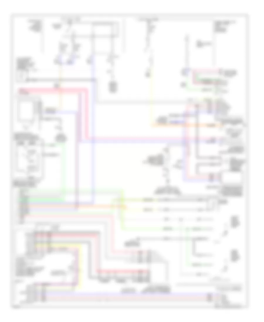
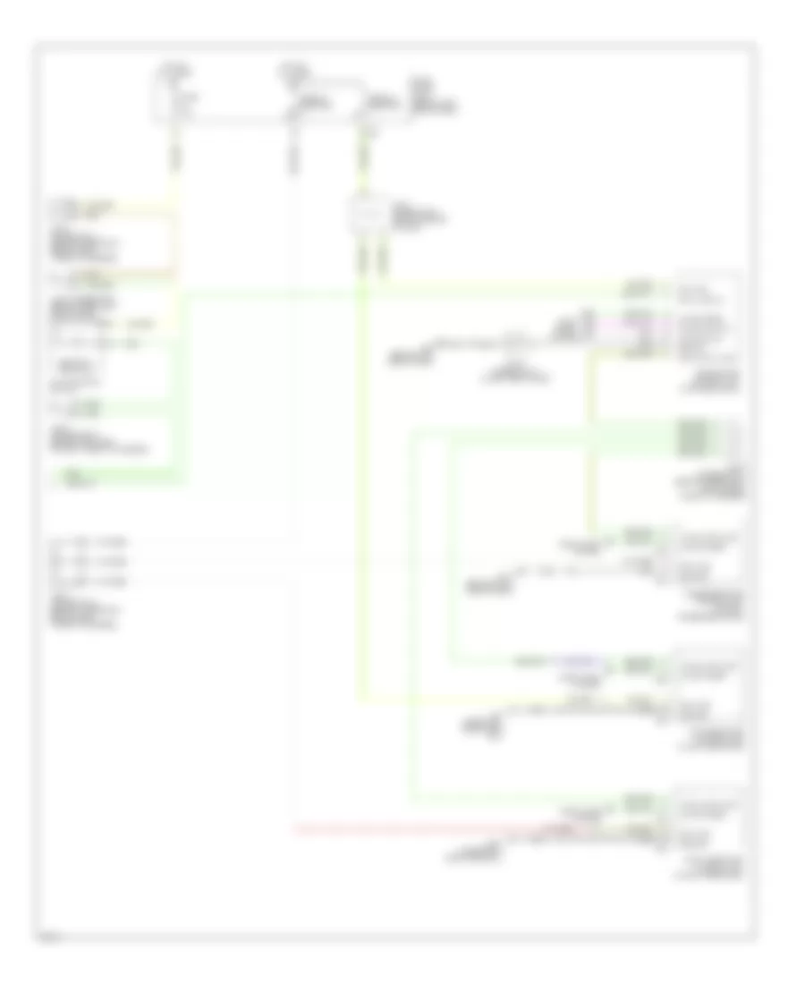
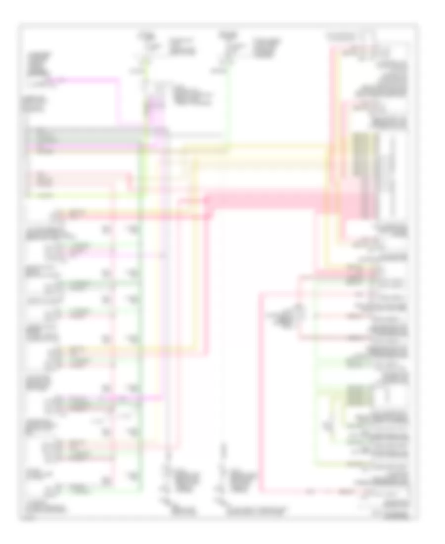
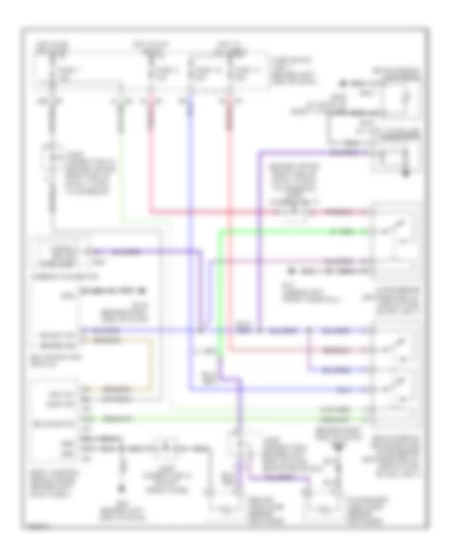
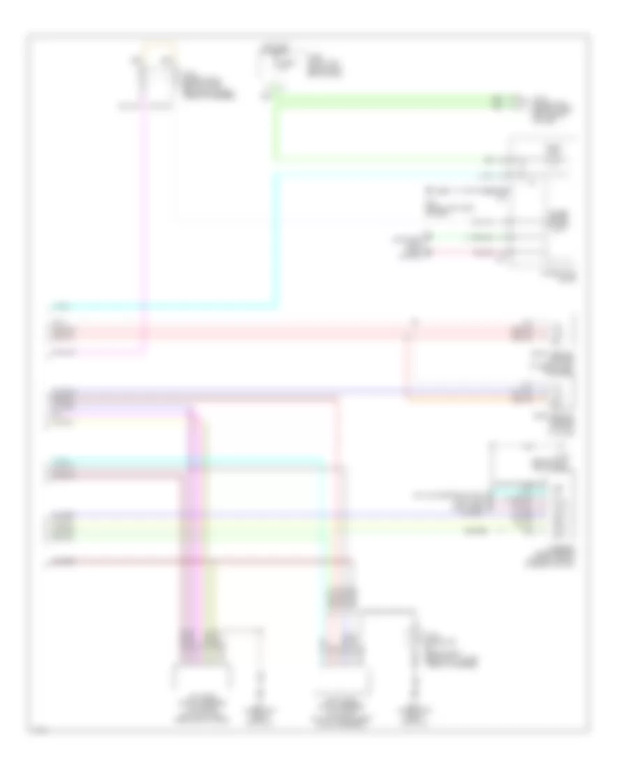
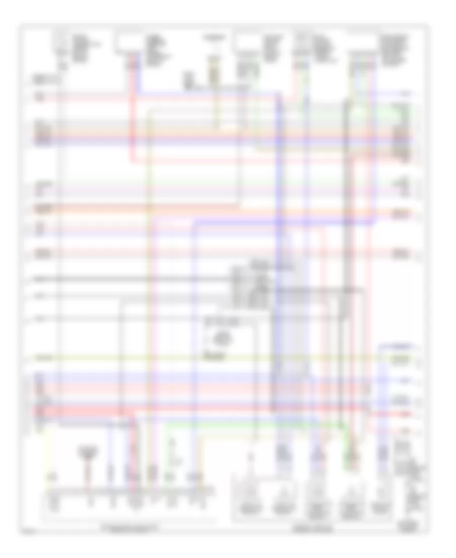
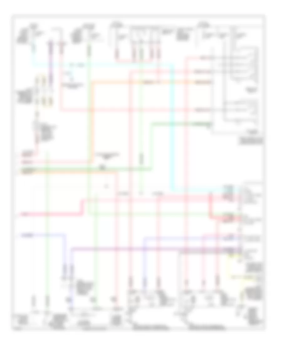
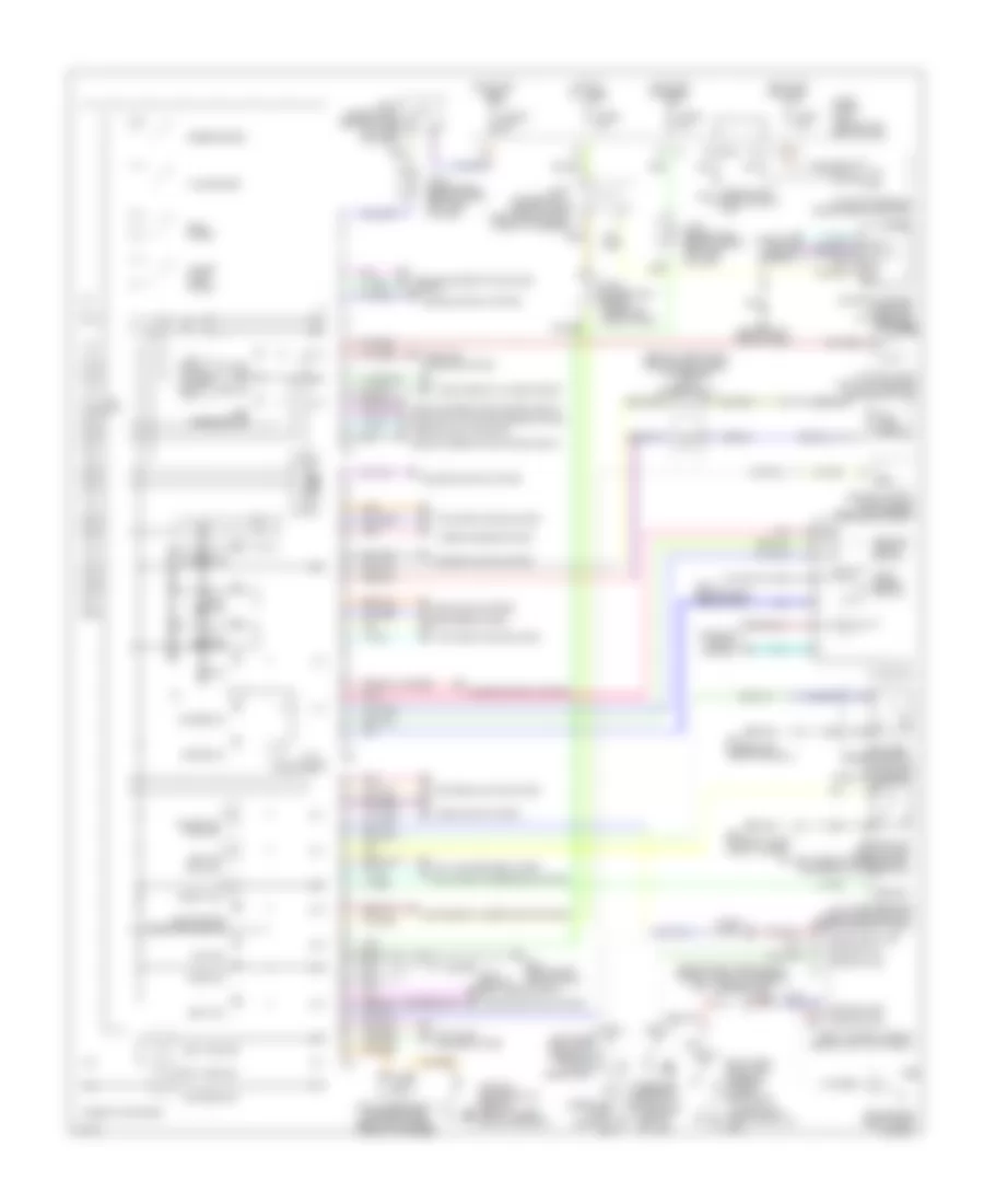
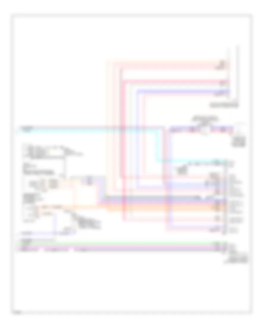
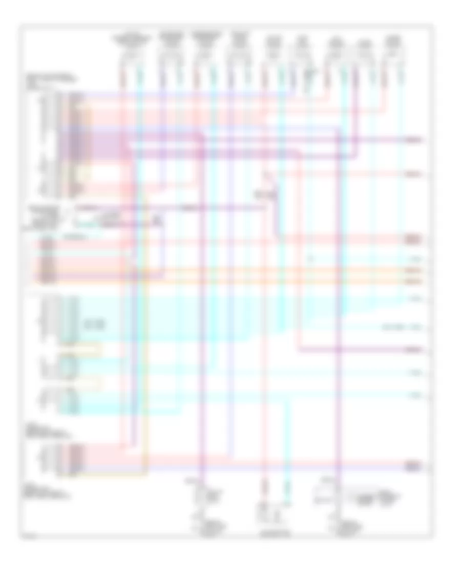
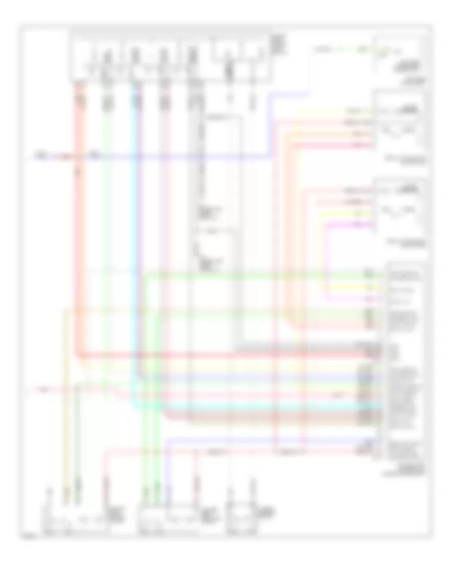
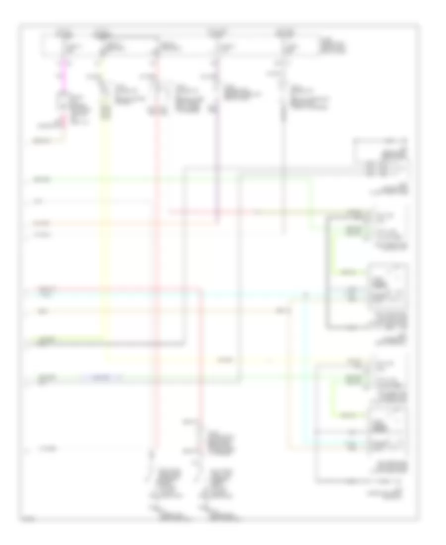
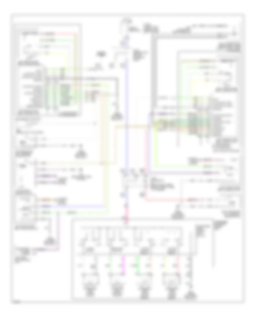
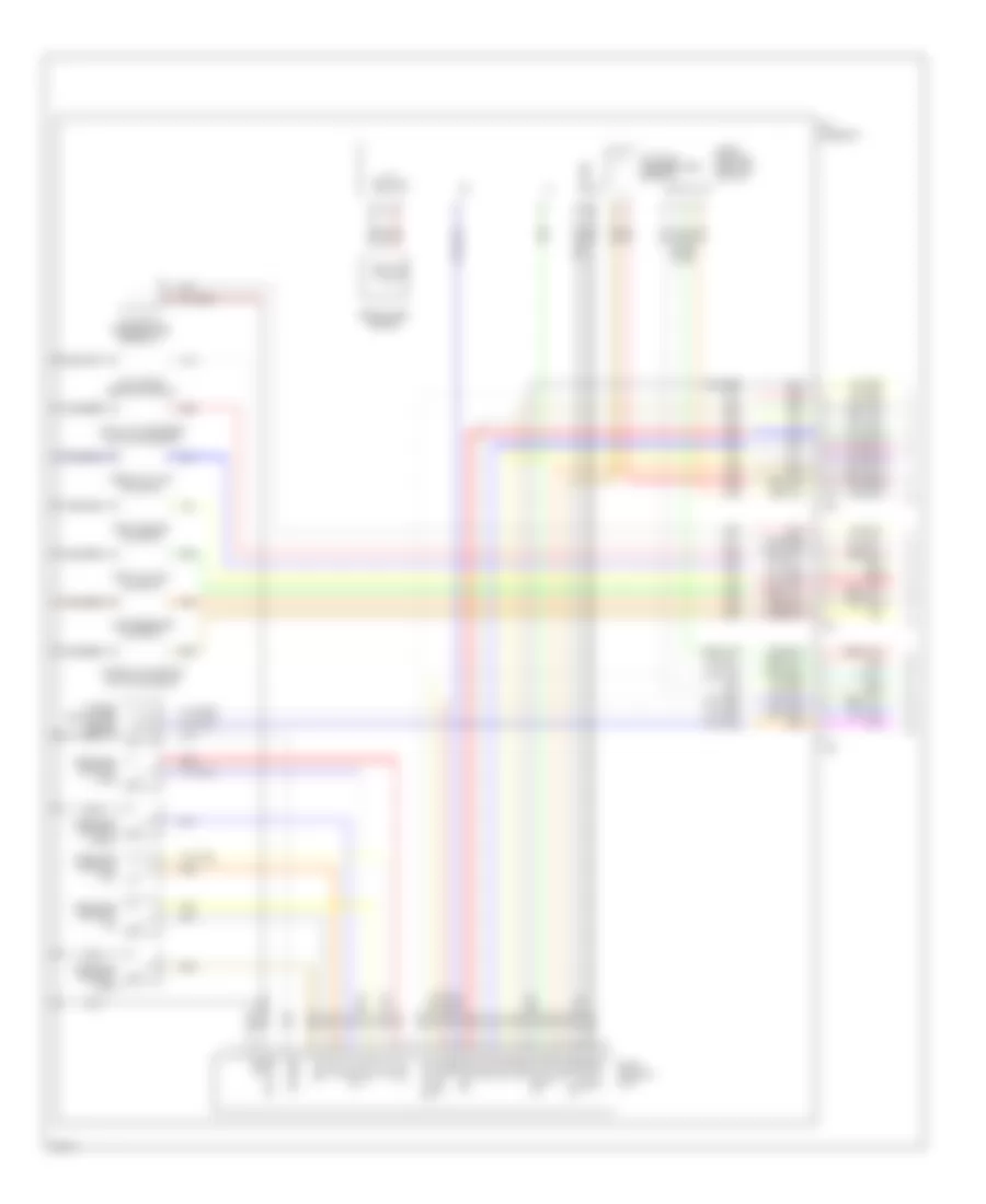
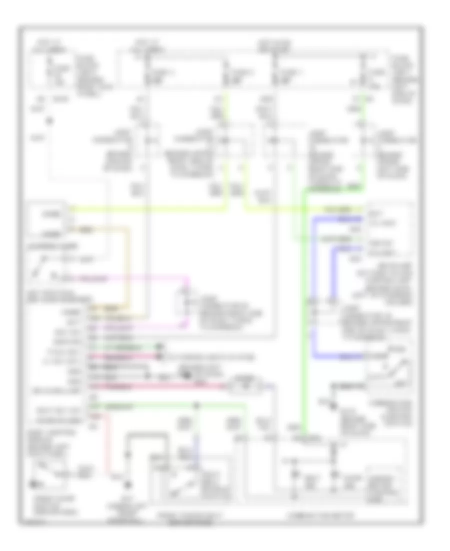
Automatic A/C Wiring Diagram (1 of 2) for Infiniti Q45 2004
 https://portal-diagnostov.com/license.html
Automotive Electricians Portal FZCO
Automotive Electricians Portal FZCO
https://portal-diagnostov.com/license.html
https://portal-diagnostov.com/license.html
Automotive Electricians Portal FZCO
Automotive Electricians Portal FZCO
List of elements for Automatic A/C Wiring Diagram (1 of 2) for Infiniti Q45 2004:
- (behind right side of dash) m114
- (behind right side of dash) m115
- (under right front door sill) b217
- 1a m1
- A/c auto amplifier (behind right side of dash)
- A/c switch
- A/c-av (fr tx)
- Acc
- Air mix door motor (passenger side) (behind right side of center console, on heater unit)
- Amb sens
- Ambient sensor (at center front of engine compt)
- Av-a/c (fr rx)
- Bat
- Clk
- Clk (fr)
- Clk (rr)
- Combination meter
- Comp on
- Computer data lines system
- Ecm comp
- Ecv
- Fan on
- Fan pwm
- Fuse 10a
- Fuse block (j/b) 1 (behind left end of dash)
- Gnd
- Ground
- Hot at all times
- Hot in acc or on
- Hot in on or start
- Ign
- In-vehicle sensor (below lower left side of dash)
- Incar sens
- Intake door motor (under right side of dash, on intake unit)
- Intake sens
- Joint connector (behind right end of dash, taped to harness)
- Joint connector (behind top center of dash, taped to harness)
- Joint connector (behind upper right end of dash, taped to harness)
- Joint connector (behind upper right side of dash, taped to harness)
- Joint connector 14 (behind upper right side of dash, taped to harness)
- Lan sig
- M119
- M120
- M25 (behind left side of dash)
- M41
- M42
- Mode door motor (passenger side) (behind right side of dash)
- Pnk
- Power windows system
- Rear control cancel relay (behind right rear wheel well)
- Rear control cancel switch
- Rear control switch
- Red
- Rr ac (rr tx)
- Rr-a/c (rr rx)
- Rr/vent actr+
- Rr/vent actr-
- Sens gnd
- Speed sens
- Sun sens
- Sunload sensor (behind left side of dash)
- Sw a/c
- Unified meter control unit
- Vactr
- W/t sens
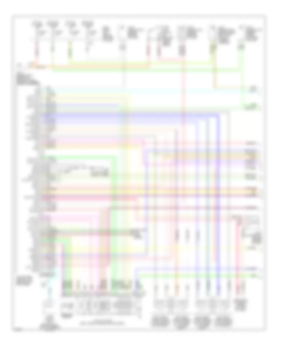
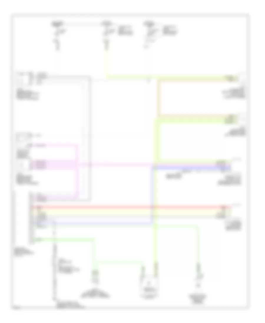
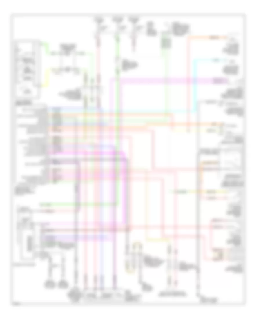
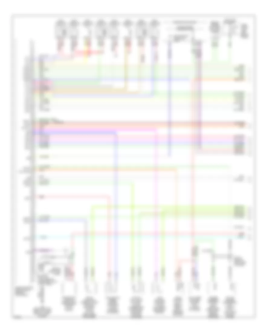
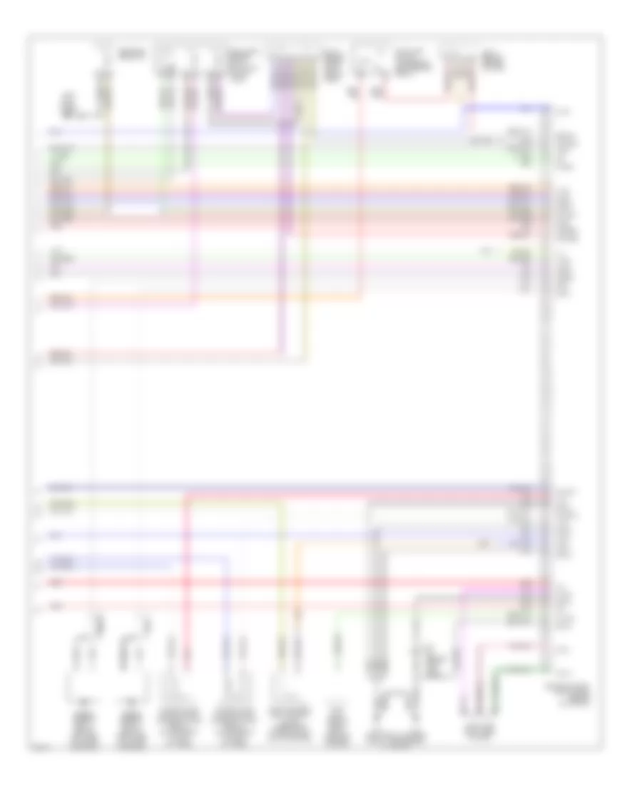
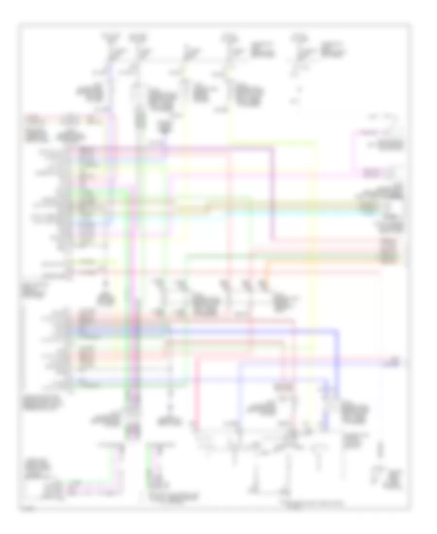
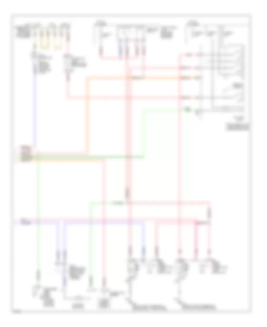
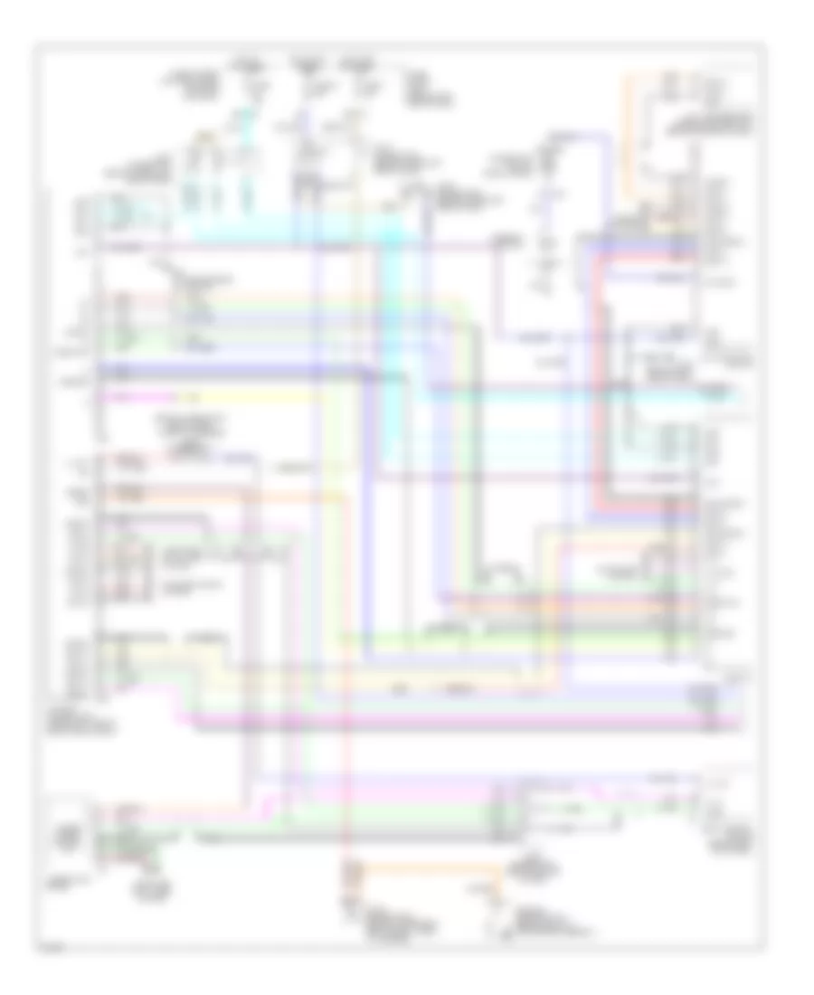
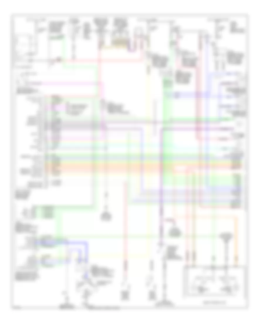
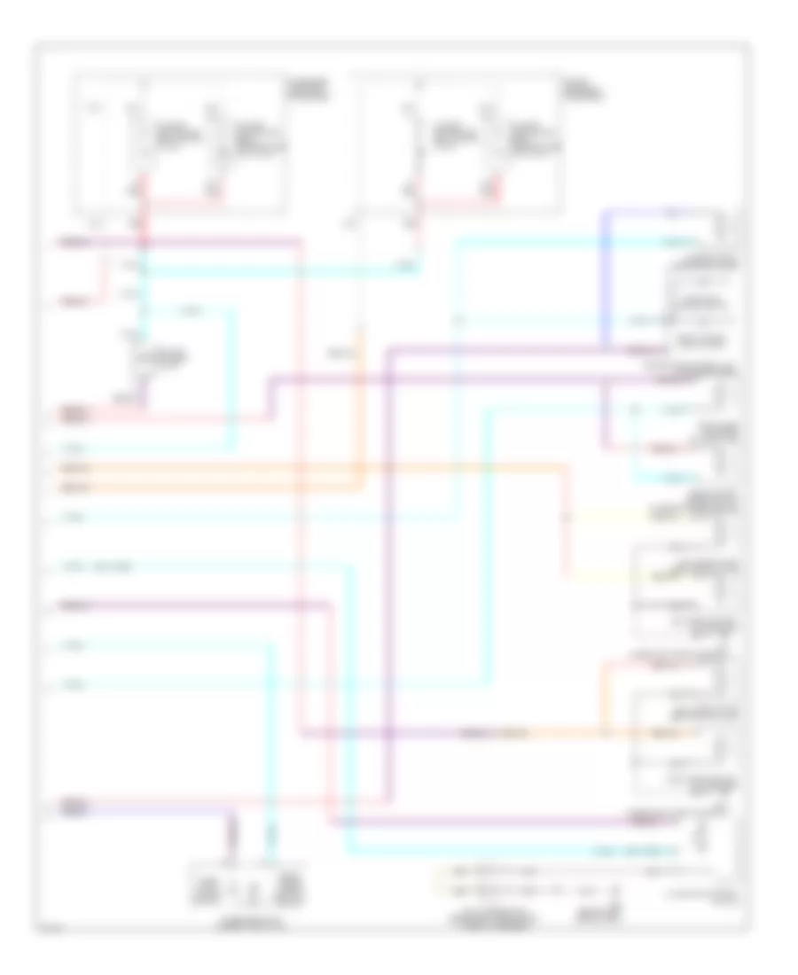
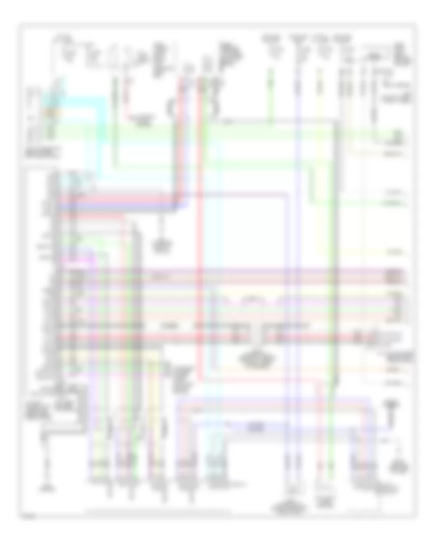
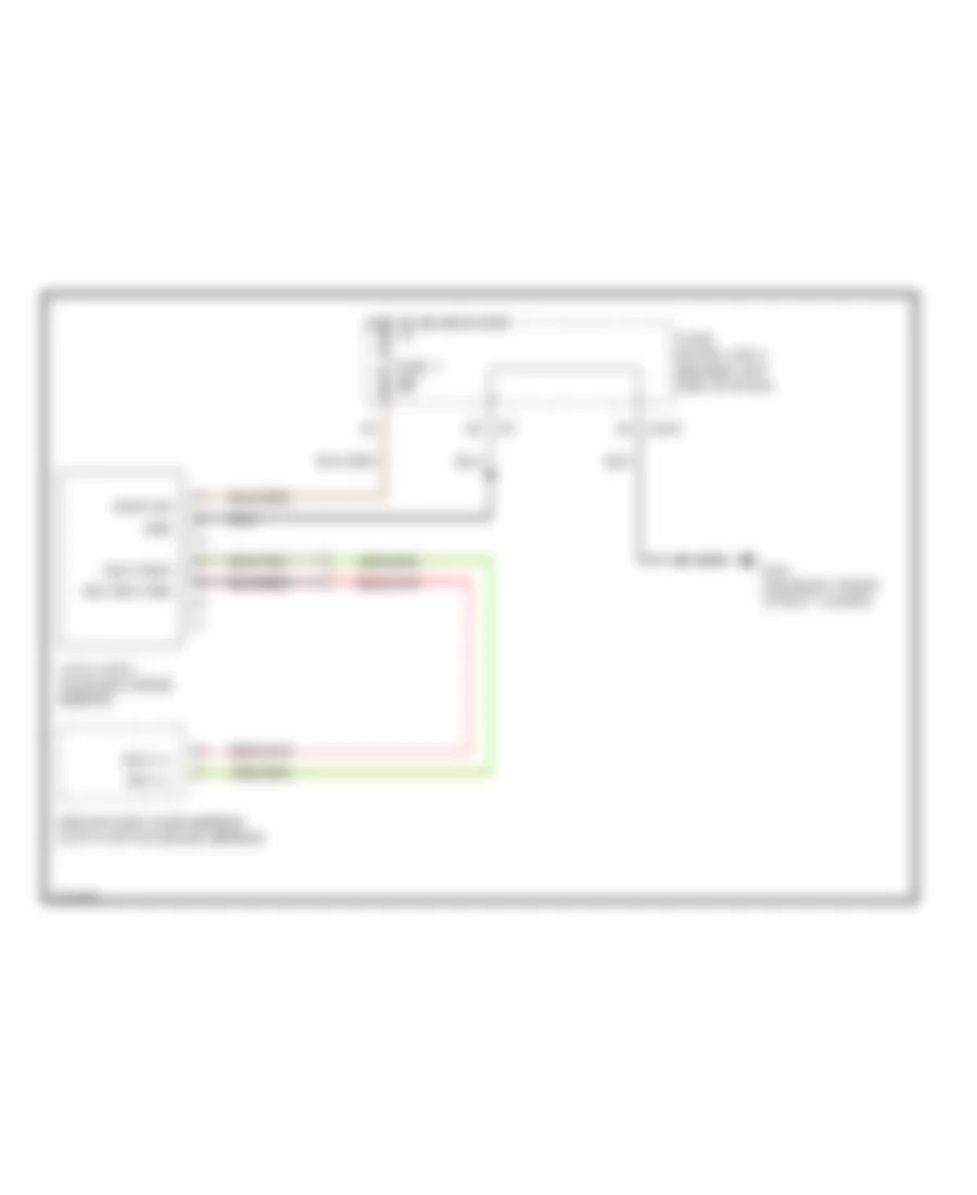
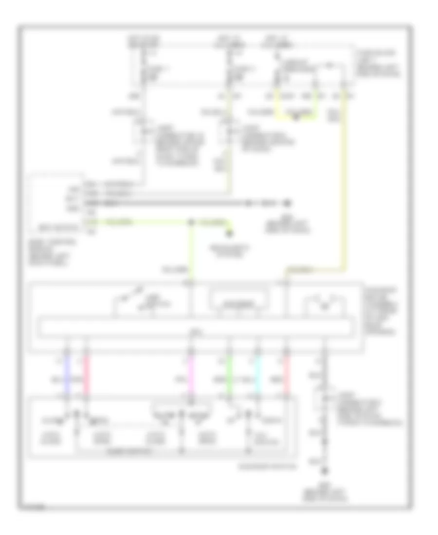
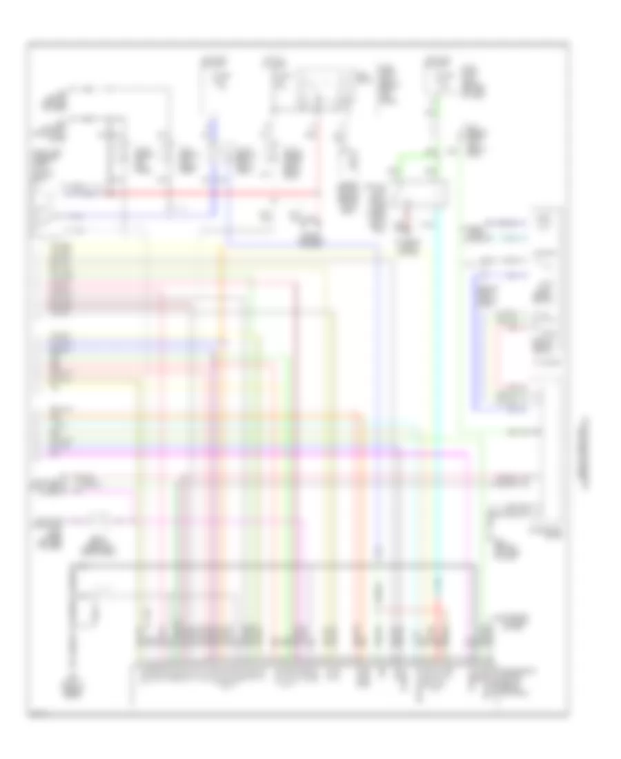
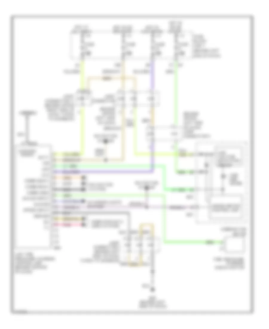
Automatic A/C Wiring Diagram (2 of 2) for Infiniti Q45 2004
List of elements for Automatic A/C Wiring Diagram (2 of 2) for Infiniti Q45 2004:
- (on top rear of engine) engine coolant temperature sensor
- 11r
- 18r e3
- 3n m145
- 5m m144
- Ac-av
- Acclk
- Acrly
- Air conditioner relay
- Air mix door motor (driver side)
- Av & navi control unit (w/ navi) av control unit (w/o navi) (w/ navi: under left side of rear parcel shelf) (w/o navi: behind center of dash)
- Av-ac
- Avcc
- B29
- Blower motor (below right side of dash, on intake unit)
- Blower relay
- Bus +
- Bus -
- Bus shield
- Can-h
- Can-l
- Close
- Closed
- Compressor (left front of engine compartment)
- Computer data lines system
- Cooling unit assembly
- Display
- Ecv solenoid valve
- Engine control module (behind glove box)
- Engine controls system
- F101
- F102
- F8 (at left front of engine compt, near engine oil level gauge)
- Fuse 10a
- Fuse 15a
- Fuse block (j/b) 2 (behind right kick panel)
- Fuse, fusible link & relay box (j/b) (in engine room box)
- Gnd-a
- Hot at all times
- Intake sensor
- Joint connector 12 (behind top center of dash, taped to harness)
- Joint connector 29 (behind right kick panel, taped to harness)
- Joint connector 30 (behind right kick panel, taped to harness)
- M114 (behind right side of dash)
- M115 (behind right side of dash)
- M77
- M83
- Magnet clutch
- Mode door motor (driver side)
- Multi-function switch
- Nca
- Open
- Pdpres
- Pnk
- Rear vent door motor (behind left front of center console)
- Red
- Refrigerant pressure sensor (at front right of engine compartment, near condenser)
- Shield
- W/ av & navi control unit
- W/ navi
- W/o navi
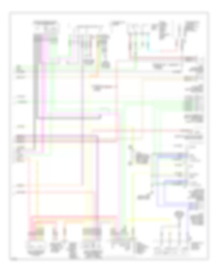
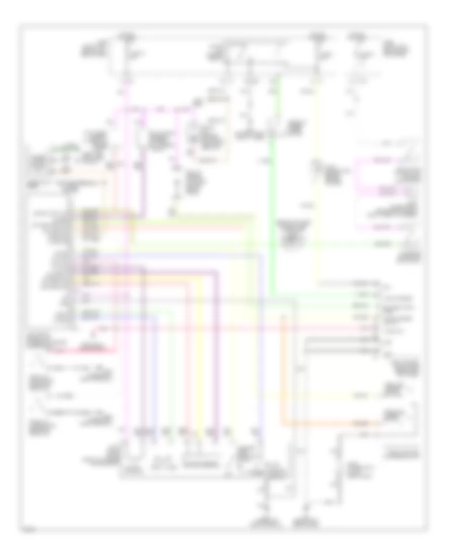
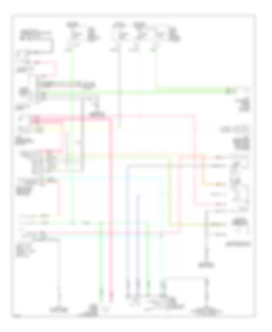
ANTI-LOCK BRAKES
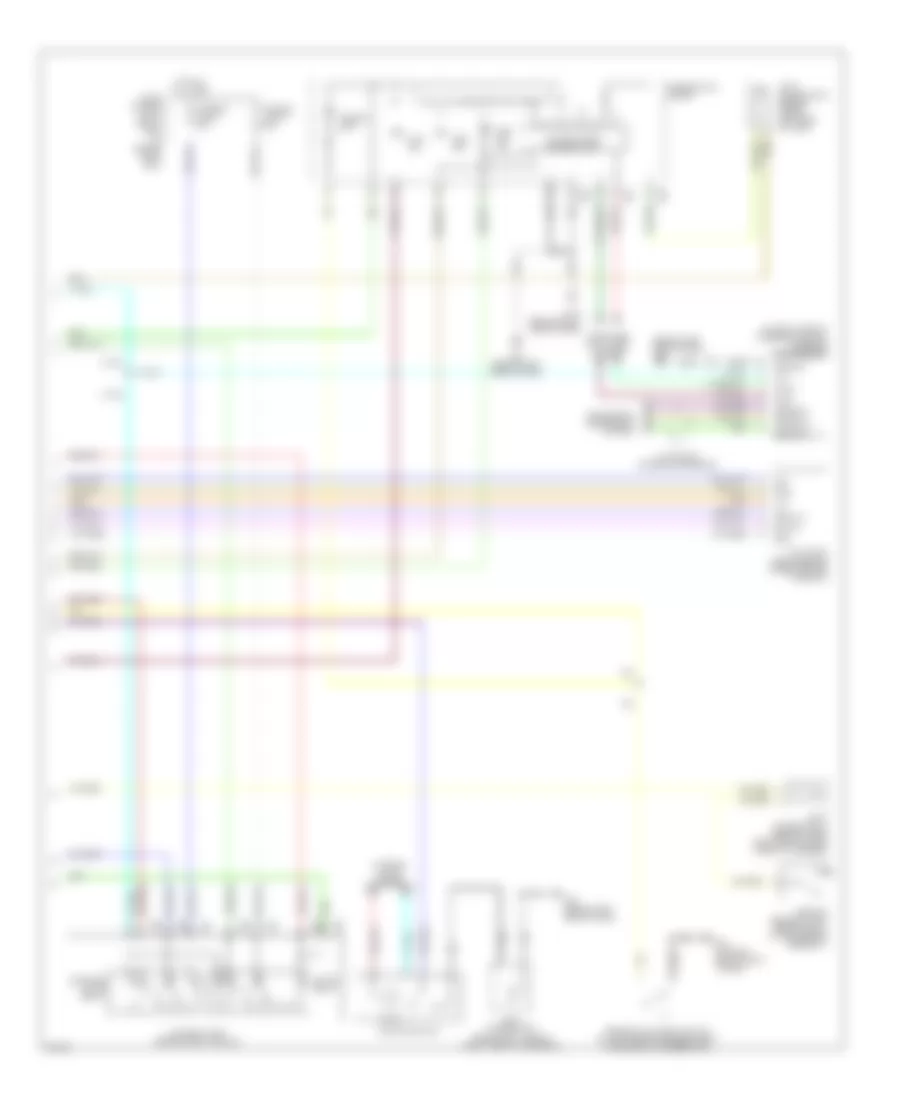
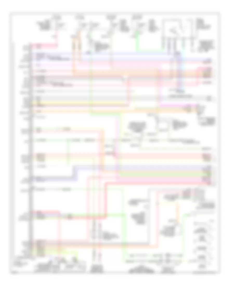
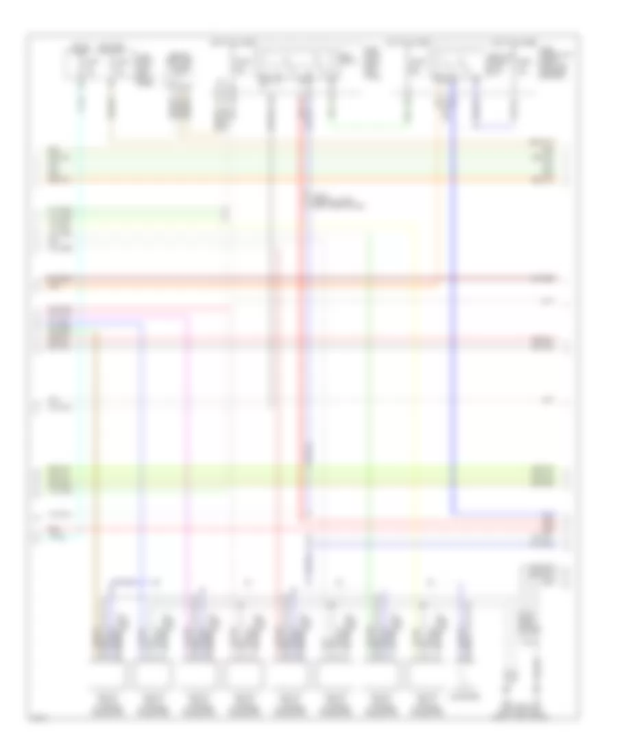
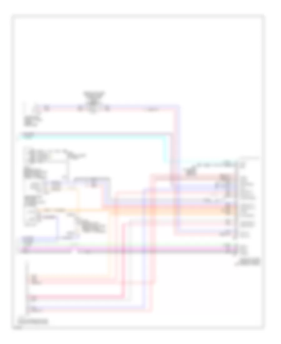
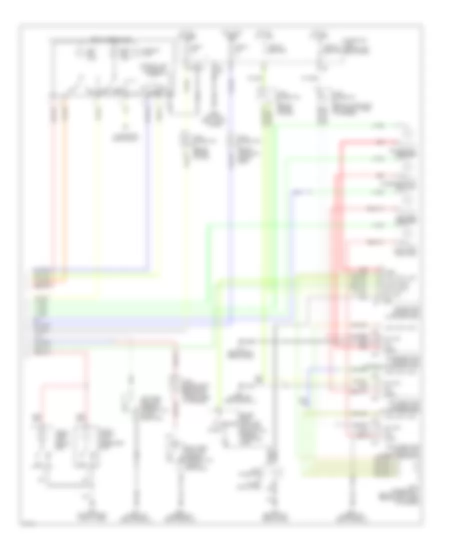
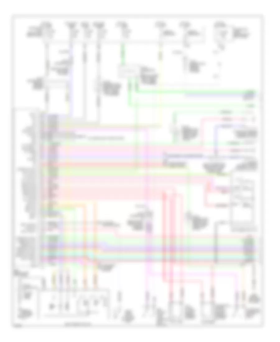
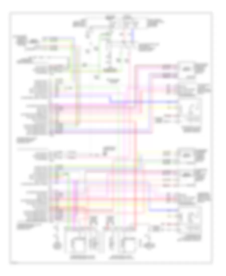
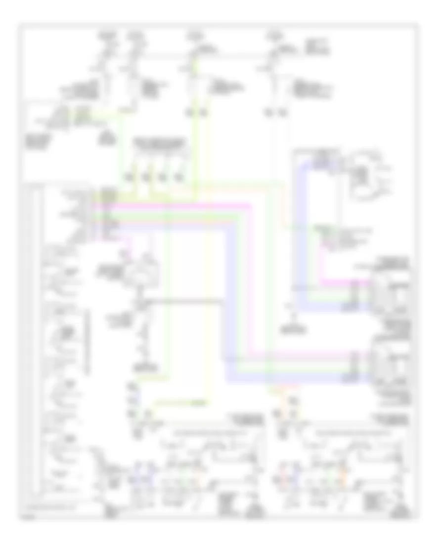
Anti-lock Brakes Wiring Diagram (1 of 2) for Infiniti Q45 2004
List of elements for Anti-lock Brakes Wiring Diagram (1 of 2) for Infiniti Q45 2004:
- (behind left end of dash)
- (on left front strut tower)
- (unused pins not shown)
- Abs w/l
- Ascd
- Ascd control unit (behind dash, left of steering column)
- Bls
- Can-h
- Can-l
- Computer data lines system
- Data link connector (under left side of dash)
- E21
- E22
- E23
- E67
- Fl mav
- Fl mv-av
- Fl mv-ev
- Fl ss
- Fl ss gnd
- Fl usv
- Fl-av4
- Fl-ev4
- Fr mav
- Fr mv-av
- Fr mv-ev
- Fr ss
- Fr ss gnd
- Fr usv
- Fr-av1
- Fr-ev1
- Fuse 17 15a
- Fuse 6 10a
- Fuse 7 10a
- Fuse 9 10a
- Fuse block (j/b) 1
- Gnd
- Gnd1
- Gnd2
- Hot at all times
- Hot in on or start
- Joint connector 11 (behind upper right side of dash, taped to harness)
- Joint connector 12 (behind top center of dash, taped to harness)
- Joint connector 4 (behind upper left side of dash)
- Joint connector 7 (behind center of dash)
- Joint connector 8 (behind center of dash)
- Joint connector 9 (behind center of dash)
- Left front wheel sensor (at left front hub assembly)
- Left rear wheel sensor (at left rear of luggage compt)
- Lis
- Mc1-mav2
- Mc1-usv2
- Mc2-mav1
- Mc2-usv1
- Pkb sw
- Pnk
- Pressure sensor
- Psm
- Pss
- Psu
- Right front wheel sensor (at right front hub assembly)
- Right rear wheel sensor (at left rear of luggage compt)
- Rl mv-av
- Rl mv-ev
- Rl ss
- Rl ss gnd
- Rl-av2
- Rl-ev2
- Rr mv-av
- Rr mv-ev
- Rr ss
- Rr ss gnd
- Rr-av3
- Rr-ev3
- Rxd
- Slip lamp
- Stop lamp switch (on bracket, above brake pedal)
- Tcs in
- Txd
- Vcc
- Vdc actuator (right rear of engine compartment)
- Vdc off lamp
- Vdc off sw
- Vdc/tcs/abs control unit (behind right kick panel)
- Vout
- W/o icc
- Yrsm
- Yrsrff
- Yrss
- Yrst
- Yrsu
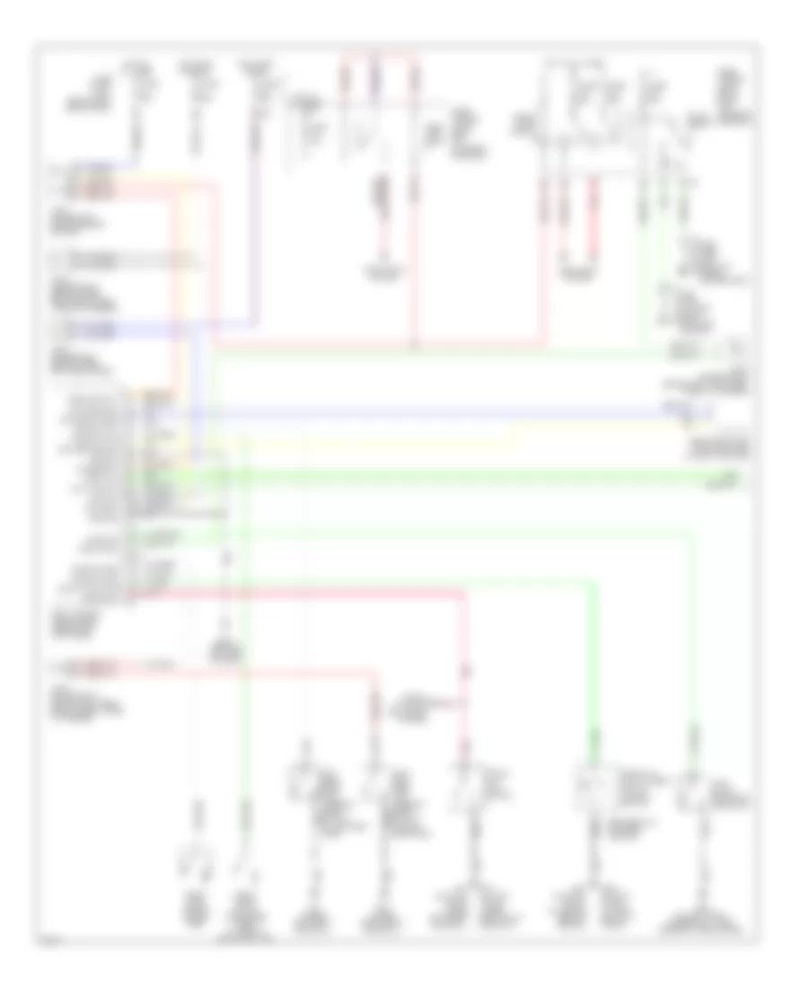
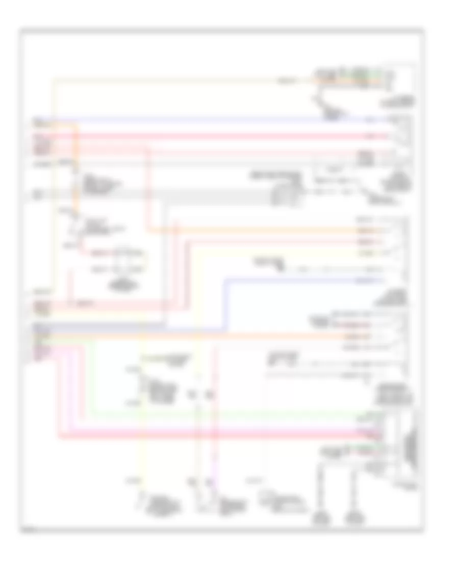
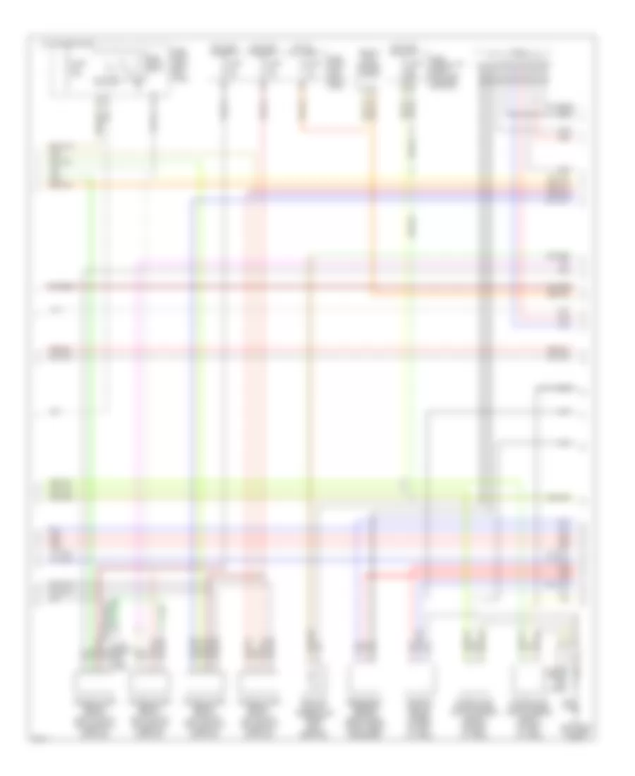
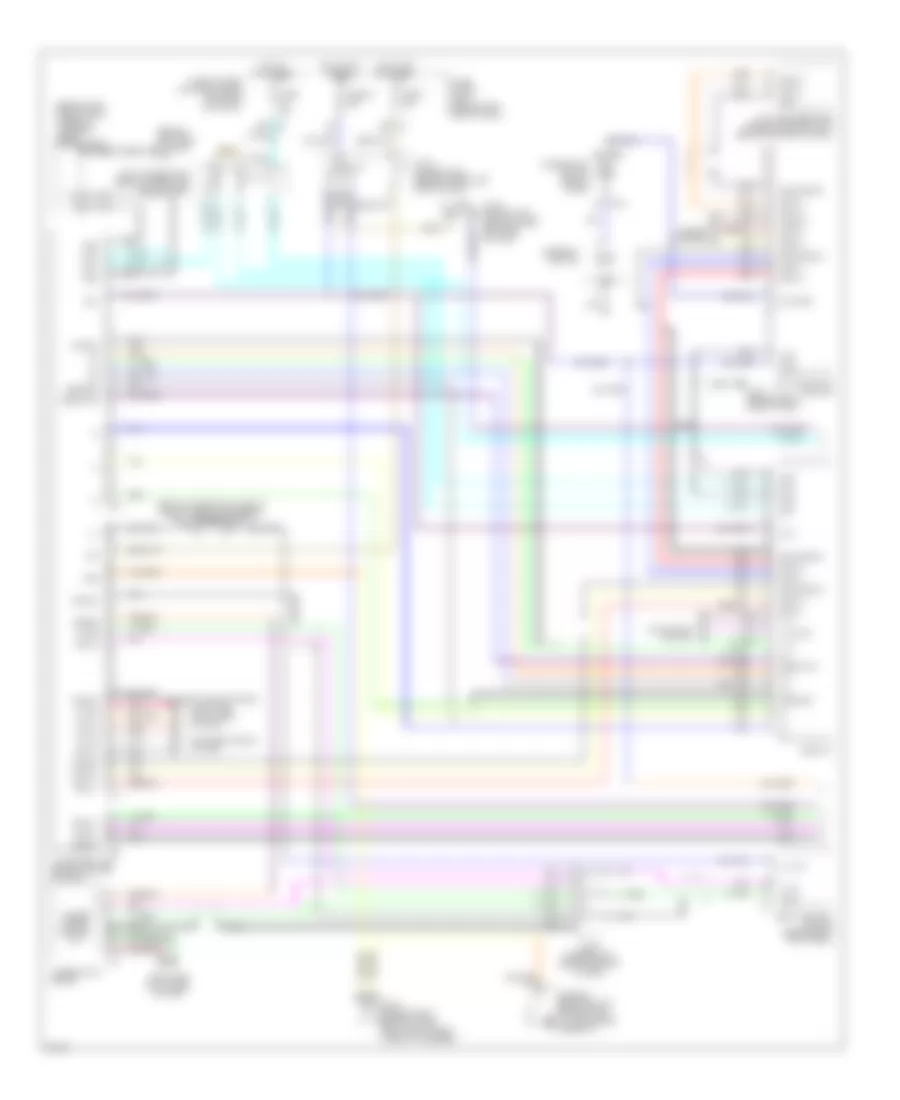
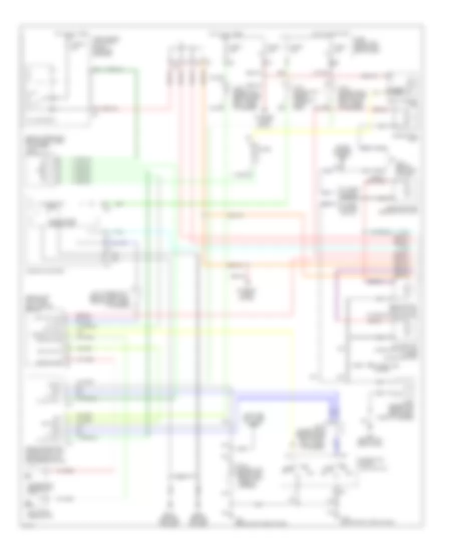
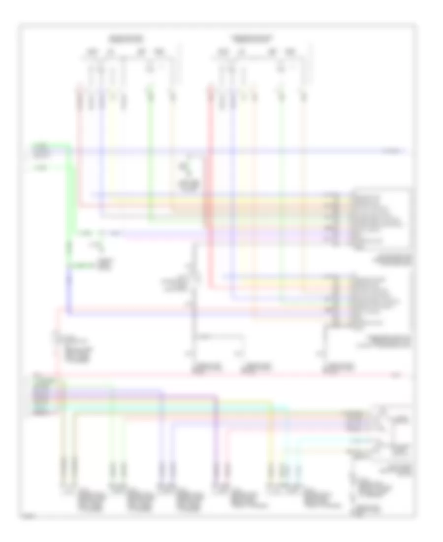
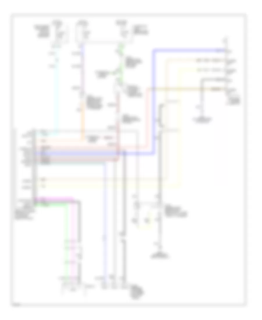
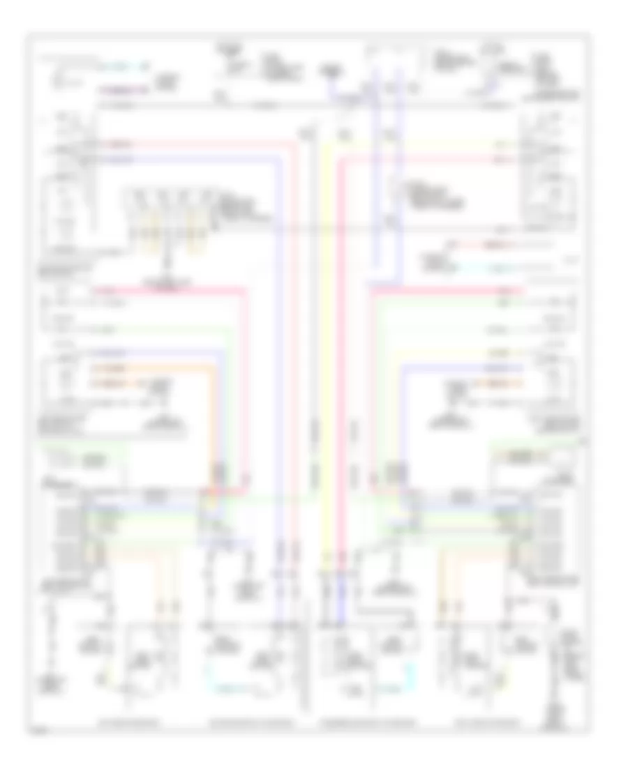
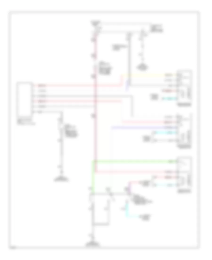
Anti-lock Brakes Wiring Diagram (2 of 2) for Infiniti Q45 2004
List of elements for Anti-lock Brakes Wiring Diagram (2 of 2) for Infiniti Q45 2004:
- (at right side of steering column) steering angle sensor
- (behind left side of dash)
- (behind left side of dash) m25
- (behind left side of dash, taped to harness)
- (on right front strut tower)
- 12v
- Abs ind
- Bite
- Brake fluid level switch (at left rear of engine compt, on brake fluid reservoir)
- Brake ind
- Bs out
- Can-h
- Can-l
- Combination meter
- Computer data lines system
- Drs out
- E24
- E55
- E56
- E57
- Electronic suspension system
- Fuse, fusible link & relay box (in engine room box)
- Fusible link f 30a
- Fusible link k 50a
- Gnd
- Ground
- Hot at all times
- Illum
- Interior lights system
- Joint connector 17 (behind upper right end of dash, taped to harness)
- Joint connector 3 (behind upper left side of dash)
- Joint connector 5
- Low voltage detection circuit
- M114 (behind right side of dash)
- M24 (behind left side of dash)
- M25
- M41
- M43
- Motor relay
- Parking brake switch (behind dash, at park brake assembly)
- Ref
- Sensor 1
- Sensor 2
- Sensor 3
- Slip ind
- Solenoid valve relay
- Unified meter control unit
- Vdc off ind
- Vdc off switch
- Vdc relay box (behind front grille)
- W/ active damper suspension
- Yaw rate/ side g sensor (under center console)
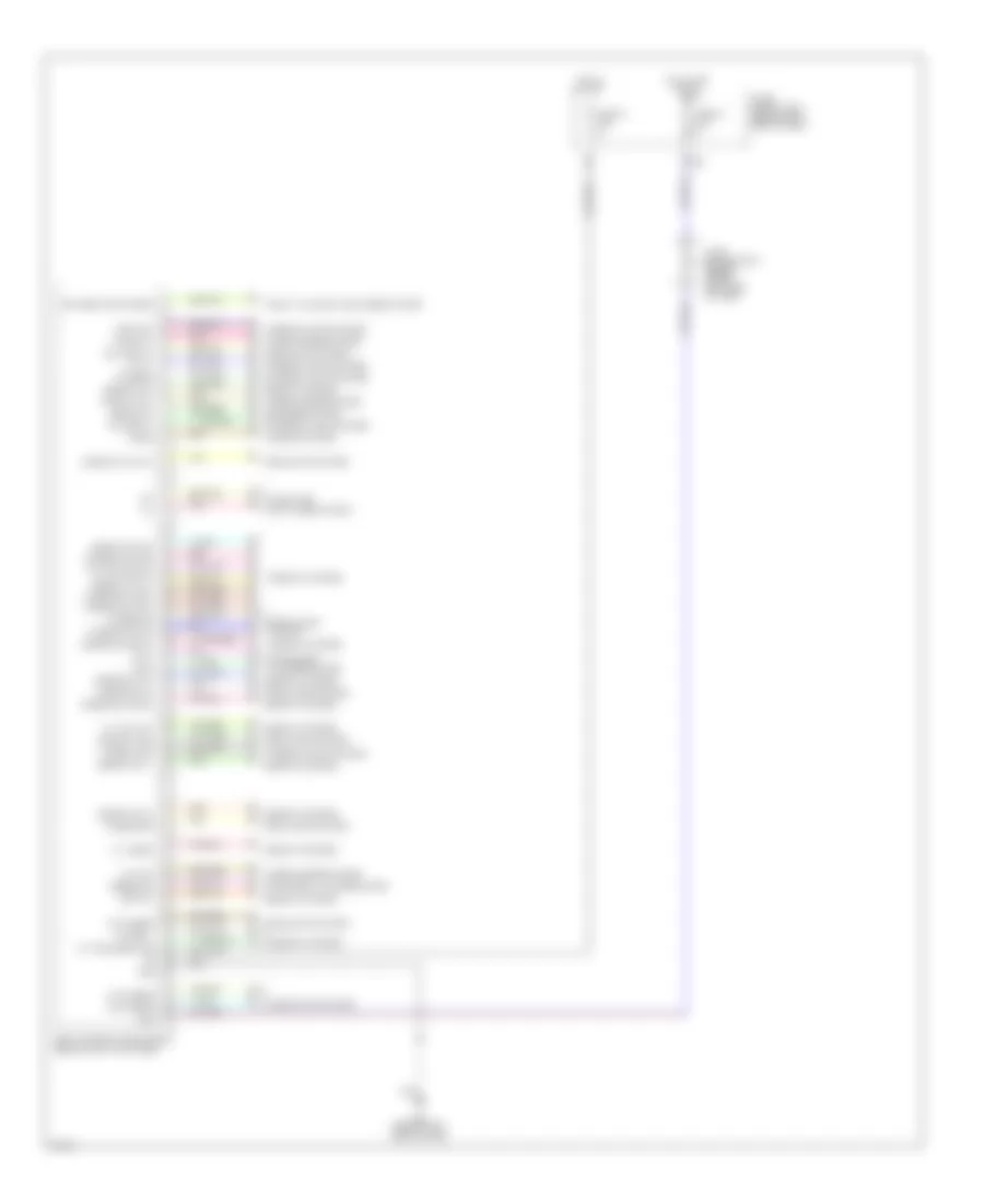
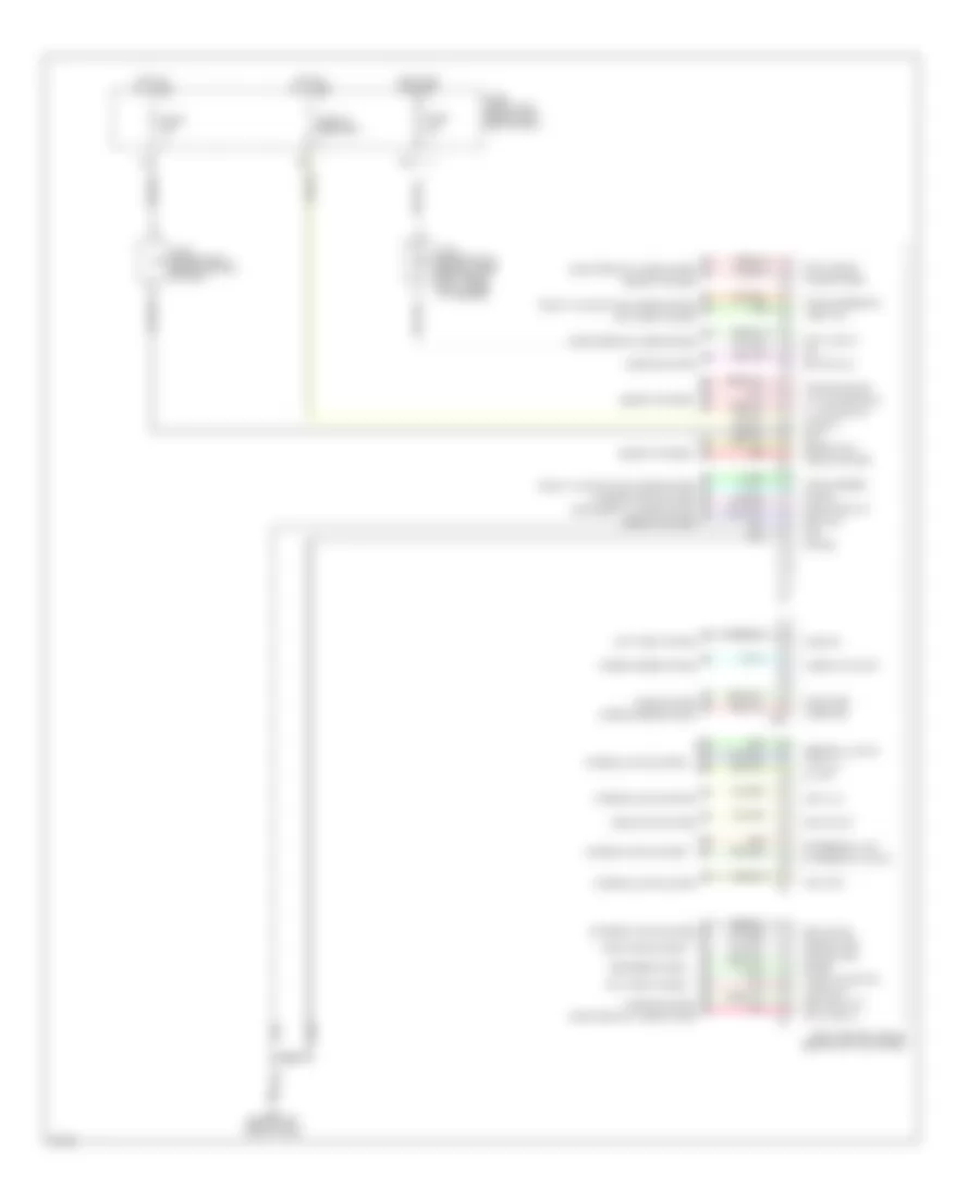
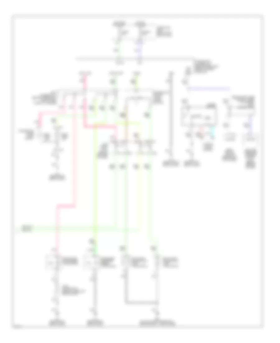
ANTI-THEFT
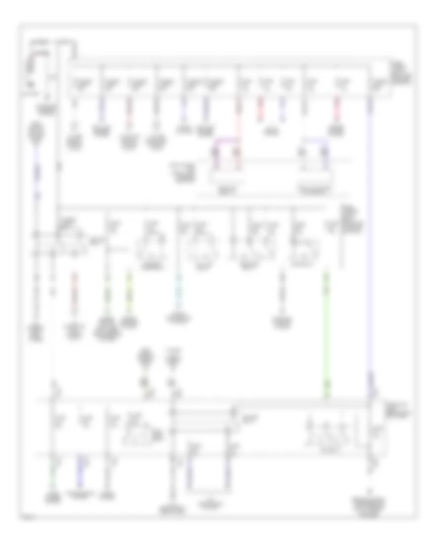
Forced Entry Wiring Diagram (1 of 2) for Infiniti Q45 2004
List of elements for Forced Entry Wiring Diagram (1 of 2) for Infiniti Q45 2004:
- (in engine room box)
- (on left front fenderwell, near engine oil level gauge)
- (under left front door sill)
- (under right front door sill)
- 13r
- 19r
- 20b
- 25r
- Accessory
- B17
- B17 (w/o auto trunk) (under left front door sill)
- B217
- B217 (w/ auto trunk) (under right front door sill)
- B256 (w/ auto trunk) (at right front of trunk)
- B57 (w/o auto trunk) (at center rear of vehicle)
- Battery
- Between full stroke & neutral
- Body control module (bcm) (behind left kick panel)
- Data line a-3
- Door sw (as)
- Door sw (dr)
- Door sw (rl)
- Door sw (rr)
- E204
- E62
- Front door switch (driver side)
- Front door switch (passenger side) (at base of right "b" pillar)
- Fuse 10a
- Fuse 15a
- Fuse 20a
- Fuse block (j/b) 1 (behind left end of dash)
- Fuse, fusible link & relay block (j/b) (in engine room box)
- Fuse, fusible link & relay box
- Ground
- Head- lamp relay
- Headlamp rly
- Headlights system
- High horn (left front of engine compartment)
- Hood sw
- Hood switch (near hood lock stay)
- Horn chirp
- Horn relay
- Hot at all times
- Hot in acc or run
- Hot in on or start
- Ignition
- Joint connector 16 (behind upper right end of dash, taped to harness)
- Joint connector 25 (behind left kick panel, taped to harness)
- Joint connector 3 (behind upper left side of dash)
- Joint connector 37 (behind right rear shock tower, taped to harness)
- Joint connector 9 (behind center of dash)
- Keyless ground
- Keyless power
- Keyless sign
- Left rear door lock assembly (door switch) (in left rear door)
- Low horn (at right front radiator support)
- M24 (behind left side of dash)
- Pnk
- Red
- Remote keyless entry receiver (at left "c" pillar)
- Right rear door lock assembly (door switch) (in right rear door)
- Theft ind
- Trunk lid key cylinder switch (unlock switch)
- Trunk lid lock switch
- Trunk sw
- Trunk unlock sw
- Trunk, tailgate, fuel doors system
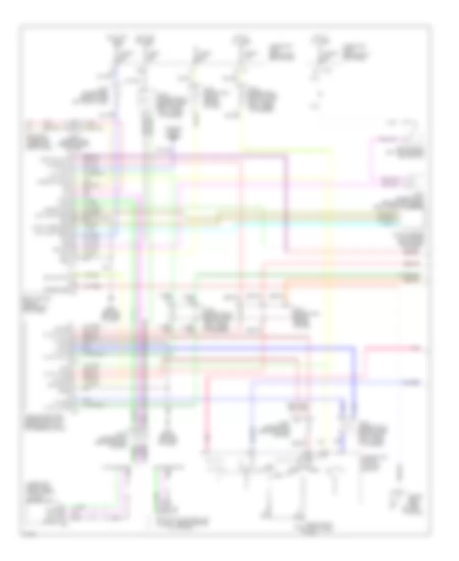
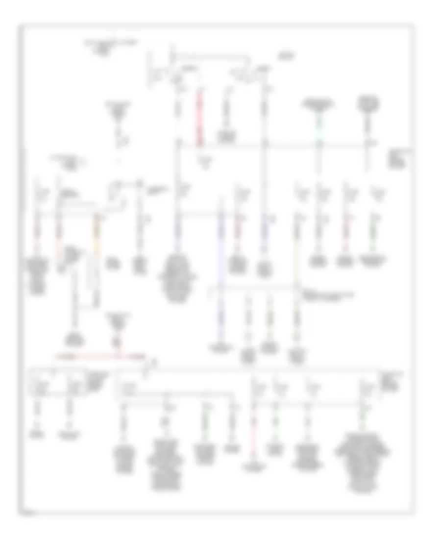
Forced Entry Wiring Diagram (2 of 2) for Infiniti Q45 2004
List of elements for Forced Entry Wiring Diagram (2 of 2) for Infiniti Q45 2004:
- B17 (under left front door sill)
- B217 (under right front door sill)
- Bat (c/b)
- Circuit breaker
- D38
- D39
- D58
- D59
- D78
- D79
- Data line a-3
- Door
- Door locks system
- Driver door control unit (in driver's door)
- Fuse 10a
- Fuse block (j/b) 1 (behind left end of dash)
- Ground
- Hot at all times
- Joint connector 11 (behind upper right side of dash, taped to harness)
- Joint connector 15 (behind upper right end of dash, taped to harness)
- Joint connector 20 (behind right side of dash, taped to harness)
- Joint connector 21 (behind lower right end of dash, taped to harness)
- Joint connector 3 (behind upper left side of dash)
- Joint connector 41 (in left front door)
- Joint connector 6 (behind center of dash)
- Left rear door control unit (in left rear door)
- Local data line
- Lock switch
- Locks
- M114 (behind right side of dash)
- M24 (behind left side of dash)
- Multifunction switch
- Passenger door control unit (in front passenger's door)
- Right rear door control unit (in right rear door)
- Security indicator
- System
- Unlock sens
- Unlock switch
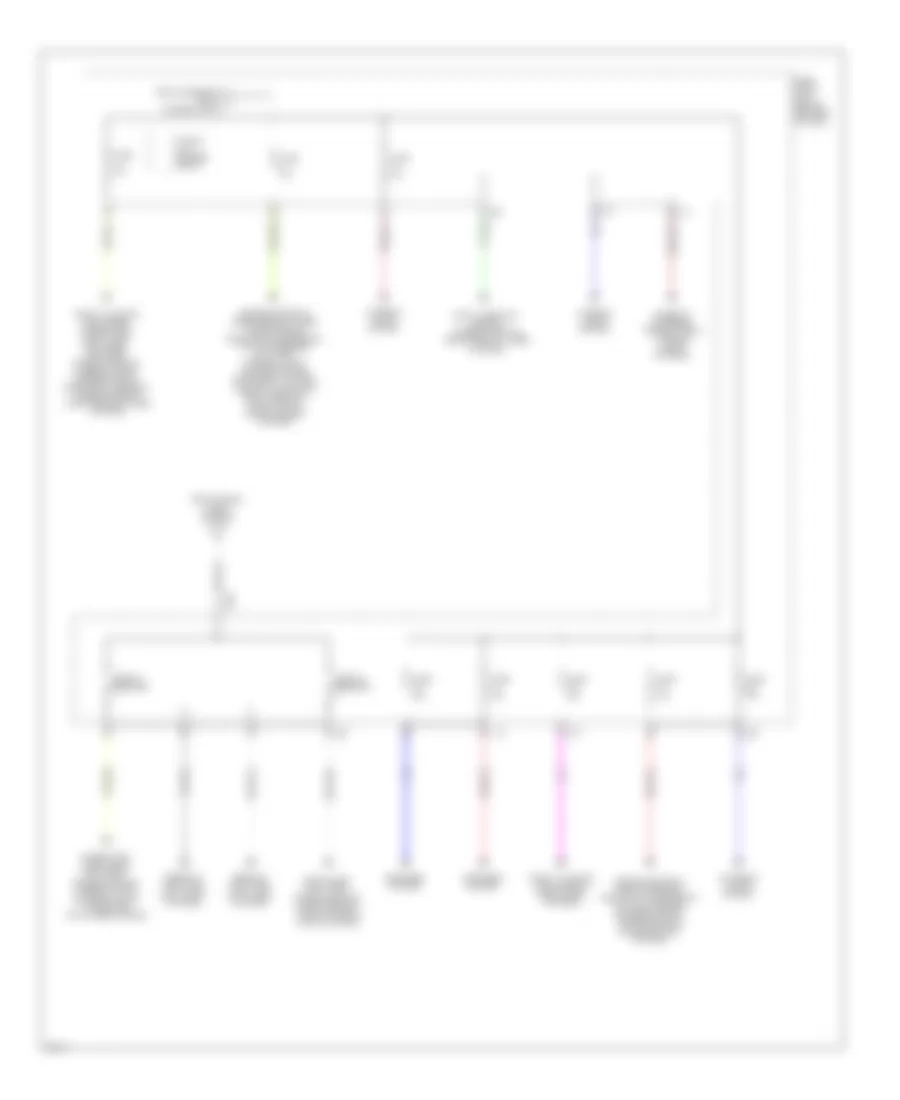
Immobilizer Wiring Diagram (NATS) for Infiniti Q45 2004
List of elements for Immobilizer Wiring Diagram (NATS) for Infiniti Q45 2004:
- (behind right kick panel, taped to harness)
- 6c m1
- 6n m145
- Engine control module (ecm) (behind glove box)
- F102
- F8 (at left front of engine compt, near engine oil level gauge)
- Fuse 1 10a
- Fuse 32 10a
- Fuse 6 10a
- Fuse block (j/b) 1 (behind left end of dash)
- Fuse block (j/b) 2 (behind right kick panel)
- Hot at all times
- Hot in on or start
- Im lime
- Joint connector
- Joint connector 11 (behind upper right side of dash, taped to harness)
- Joint connector 16 (behind upper right end of dash, taped to harness)
- Joint connector 20 (behind right side of dash, taped to harness)
- Joint connector 3 (behind upper left side of dash)
- Key switch & key lock solenoid (key switch)
- M115 (behind right side of dash)
- Multi-function switch
- Nats antenna amplifier (behind right side of dash)
- Nats immu (behind dash, left of steering column)
- Red
- Security indicator
- Steering lock control unit (behind dash, right of steering column)
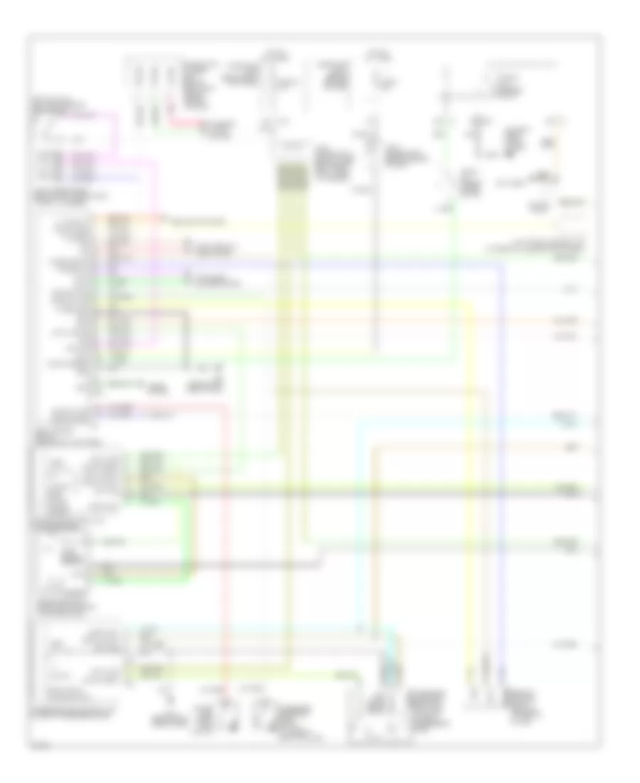
BODY CONTROL MODULES
Body Control Modules Wiring Diagram (1 of 2) for Infiniti Q45 2004
List of elements for Body Control Modules Wiring Diagram (1 of 2) for Infiniti Q45 2004:
- (tilt sw (down)
- (behind left kick panel)
- A/d grd
- Acc
- Auto sens
- Body control module (bcm)
- Chime
- Combo sw (auto)
- Computer data lines system
- D/mirr lamp
- Defog sw
- Defogger system
- Detent sw
- Door locks system
- Door sw (as)
- Door sw (rl)
- Exterior lights system
- Flasher
- Fuse 14 10a
- Fuse 21 10a
- Fuse block (j/b) 1 (behind left end of dash)
- Gnd
- Hdlt relay
- Headlights system
- Hot in acc or on
- Hot in start
- Iiurx
- Iiutx
- Ill out
- Instrument cluster system
- Int (vr)
- Interior lights system
- Joint connector 3 (behind upper left side of dash)
- K/less gnd
- K/less sig
- K/less sig pwr
- Keyless trunk open
- Light sw
- M24 (behind left side of dash)
- Memory sw 1
- Memory sw 2
- Memory systems
- Mirror sw down
- Mirror sw left
- Mirror sw right
- Mirror sw up
- Pnk
- Red
- Select sw lh
- Select sw rh
- Set sw
- Speed sig
- Tail relay
- Telesco sw (fr)
- Tilt sens
- Tilt sw (up)
- Tilt/tele sen pwr
- Trunk, tailgate, fuel doors system
- Warning system
- Wash sw
- Wiper/washer system
- Wipr int sw
Body Control Modules Wiring Diagram (2 of 2) for Infiniti Q45 2004
List of elements for Body Control Modules Wiring Diagram (2 of 2) for Infiniti Q45 2004:
- 20b
- A/d batt
- A/d gnd
- All off
- Anti-theft system
- Batt
- Body control module (behind left kick panel)
- Circuit breaker 1
- Computer data lines system
- Data line a-1
- Data line a2
- Data line a3
- Defogger system
- Door locks system
- Door sw (dr)
- Door sw (rr)
- Door warn lmp
- E204
- Exterior lights system
- Fuse 1 10a
- Fuse 3 10a
- Fuse block (j/b) 1 (behind left end of dash)
- Gnd
- Headlights system
- Hood sw
- Horn chrp
- Horns system
- Hot at all times
- Hot in on or start
- Ign
- Ign key
- Instrument cluster system
- Interior lights system
- Joint connector 16 (behind upper right end of dash, taped to harness)
- Joint connector 9 (behind center of dash)
- Key switch
- M24 (behind left side of dash)
- Map/l (lh)
- Map/l (rh)
- Mem ind 2
- Memory ind 1
- Memory systems
- Personal lmp sw
- Pnk
- Rap output
- Red
- Rev-lmp sw
- Rl personal lmp (rl)
- Rr def
- Rr personal lmp
- Seat belt sw
- Tele motor (fr)
- Tele motor (rr)
- Telesco sens
- Theft ind
- Tilt motor (down)
- Tilt motor (up)
- Total ill
- Trunk opener
- Trunk opener sw
- Trunk sw
- Trunk unlock sw
- Trunk, tailgate, fuel doors system
- Warning system
- Wiper amp
- Wiper auto stop
- Wiper/washer system
COMPUTER DATA LINES
Computer Data Lines Wiring Diagram for Infiniti Q45 2004
List of elements for Computer Data Lines Wiring Diagram for Infiniti Q45 2004:
- (behind left end of dash)
- (under left side of dash) data link connector
- (under rear of center console) air bag diagnosis sensor unit
- 33r e3
- 6c m1
- Active damper suspension control unit
- Ascd control unit (behind dash, left of steering column)
- Av control unit (w/o navigation) av & navi control unit (w/ navigation) (w/o navigation: behind center of dash) (w/ navigation: under left side of rear parcel shelf)
- Av-cn
- B29
- B37
- Body control module (bcm) (behind left kick panel)
- Can h
- Can l
- Cn-av
- Combination meter
- D38
- D58
- D78
- Data line a1
- Data line a2
- Data line a3
- Ddl-rx
- Ddl-tx
- Driver seat control unit
- Drivers door control unit (in driver's door)
- Drivers side door mirror control unit (in driver's door)
- Engine control module (behind glove box)
- F102
- F103
- F8 (at left front of engine compt, near engine oil level gauge)
- Front power seat (driver side)
- Fuse 58 10a
- Fuse 6 10a
- Fuse block (j/b) 1
- Fuse, fusible link & relay block (j/b) (in engine room box)
- Hot at all times
- Hot in on or start
- Icc sensor (at front center of engine compartment)
- Icc unit (at right side of trunk)
- Joint connector 11 (behind upper right side of dash, taped to harness)
- Joint connector 15 (behind upper right end of dash, taped to harness)
- Joint connector 18 (behind center of dash)
- Joint connector 29 (behind right kick panel, taped to harness)
- Joint connector 5 (behind left side of dash, taped to harness)
- Joint connector 8 (behind center of dash)
- K-line
- Kline
- Left rear door control unit (in left rear door)
- Local data line
- Low tire pressure warning control unit (behind left side of dash)
- M103
- M143
- M25 (behind left side of dash)
- M35
- M41
- M77
- M84
- Passenger door control unit (in front passenger's door)
- Passenger side door mirror control unit (in front passenger's door)
- Pnk
- Right rear door control unit (in right rear door)
- Rxd
- Rxi
- Steering angle sensor (at right side of steering column)
- Transmission control module (behind glove box)
- Txd
- Txi
- Vdc/tcs/abs control unit (behind right kick panel)
- W/ icc
- W/ navigation
- W/o navigation
CRUISE CONTROL
Cruise Control Wiring Diagram for Infiniti Q45 2004
List of elements for Cruise Control Wiring Diagram for Infiniti Q45 2004:
- (spiral cable) combination switch
- 21r
- 24r
- 29r
- 31r
- Actr high side
- Air valve
- Air valve low side
- Ascd
- Ascd brake switch (on bracket, above brake pedal)
- Ascd control unit (behind dash, left of steering column)
- Ascd pump (at right rear corner of engine compt)
- Ascd steering wheel switch
- Brake sw input
- Cancel switch
- Combination meter
- Computer data lines system
- Control sw (a/d) input
- Control sw input (gnd)
- Cruise ind
- Cruise lamp input
- Data link connector (under left side of dash)
- Dual mode muffler control unit (at right side of trunk)
- E24 (on right front strut tower)
- Ecm prun input
- Engine control module (behind glove box)
- Etc prun
- F101
- F102
- F104
- F8 (at left front of engine compt, near engine oil level gauge)
- Fuse 12 10a
- Fuse 17 15a
- Fuse 9 10a
- Fuse block (j/b) 1 (behind left end of dash)
- Fuse, fusible link & relay block (j/b) (in engine room box)
- Gnd
- Gnd-c
- Hot at all times
- Hot in on or start
- Ign sw
- Joint connector 12 (behind top center of dash, taped to harness)
- Joint connector 16 (behind upper right end of dash, taped to harness)
- Joint connector 18 (behind upper right end of dash, taped to harness)
- Joint connector 4 (behind upper left side of dash)
- Joint connector 5 (behind left side of dash, taped to harness)
- Joint connector 7 (behind center of dash)
- Joint connector 8 (behind center of dash)
- M114 (behind right side of dash)
- M24 (behind left side of dash)
- M25 (behind left side of dash)
- M41
- M42
- M43
- M441
- M53
- Main switch
- Motor low side
- Od cancel sig
- Park/neutral position relay
- Pnk
- Rel valve low side
- Release valve
- Resume/ accel sw
- Rxi
- Set ind
- Set lamp output
- Set/ coast switch
- Solenoid monitor input
- Start rly
- Stoplight switch (on bracket above brake pedal)
- Tcs input
- Throttle position input
- Transmission control module (behind glove box)
- Tvo0
- Txi
- Unified meter control unit
- Vacuum motor
- Vdc/tcs/abs control unit (behind right kick panel)
- Vehicle speed input
Intelligent Cruise Control Wiring Diagram (1 of 2) for Infiniti Q45 2004
List of elements for Intelligent Cruise Control Wiring Diagram (1 of 2) for Infiniti Q45 2004:
- (on right front fenderwell, forward of engine room box) e42
- (under left side of dash, near ascd control unit) icc warning chime
- 19b
- Accel/ resume sw
- Air valve
- Ascd pump (at right rear corner of engine compt)
- B243
- B244
- B245
- Bat-1
- Bat-2
- Bnc-sw
- Bno-sw
- Brake pressure sensor (at left rear of engine compt)
- Buzz
- Can-h
- Can-l
- Cancel switch
- Coast/ set switch
- Combination switch (spiral cable)
- Computer data lines system
- Cruise
- Data link connector (under left side of dash)
- Ddl-rx
- Ddl-tx
- Distance switch
- Dual mode muffler control unit (at right side of trunk)
- E215
- Engine control module (ecm) (behind glove box)
- Engine controls system
- F102
- Front wiper motor (on left side of firewall)
- Fuse 1 10a
- Fuse 17 15a
- Fuse 34 20a
- Fuse 77 10a
- Fuse 9 10a
- Fuse block (j/b) 1 (behind left end of dash)
- Fuse block (j/b) 2 (behind right kick panel)
- Fuse, fusible link & relay box (in engine room box)
- Gnd
- Gnd-1
- Gnd-2
- Gnd-3
- Gnd-a
- Gnd-s
- Gnd/sw 1
- Hot at all times
- Hot in on or start
- Icc steering switch
- Icc unit (at right side of trunk)
- Ign-1
- Ign-2
- Instrument cluster system
- Joint connector 12 (behind top center of dash, taped to harness)
- Joint connector 3 (behind upper left side of dash)
- Joint connector 30 (behind right kick panel, taped to harness)
- Joint connector 4 (behind upper left side of dash)
- Joint connector 8 (behind center of dash)
- M441
- M53
- Od cancel
- On/off switch
- Pkb sw
- Pnk
- Psen-gnd
- Psen-pwr
- Psen-sig
- Red
- Release valve
- Rls-nc
- Rls-no
- Rls-pwr
- Safety
- Sig/sw 2
- Sol +
- Sol -
- Stp-lmp
- T-rly
- Tvo
- Tvo0
- Vacuum motor
- Vacuum mtr
- Vent
- Vout
- Vpwr
- Warn
- Wip-h
- Wip-l
- Wiper/washer system
Intelligent Cruise Control Wiring Diagram (2 of 2) for Infiniti Q45 2004
List of elements for Intelligent Cruise Control Wiring Diagram (2 of 2) for Infiniti Q45 2004:
- (behind right rear shock tower, taped to harness) joint connector 36
- (on right front strut tower) e24
- (with icc indicator)
- 14r
- 15r
- 21r
- 24r
- 29r
- 31r
- B217 (under right front door sill)
- Boost solenoid
- Brake booster (left rear of engine compt)
- Can-h
- Can-l
- Combination meter
- Computer data lines system
- Control unit unified meter
- E24 (on right front strut tower)
- F104
- Fuse, fusible link & relay block (j/b) (in engine room box)
- Gnd
- Icc brake hold relay (at right side of engine compt)
- Icc brake switch (on bracket, above brake pedal)
- Icc sensor (at front center of engine compt)
- Ign
- Instrument cluster system
- Joint connector 12 (behind top center of dash, taped to harness)
- Joint connector 17 (behind upper right end of dash, taped to harness)
- Joint connector 7 (behind center of dash)
- M114 (behind right side of dash)
- M24 (behind left side of dash)
- M41
- M42
- M43
- Nca
- Park/neutral position relay
- Parking brake switch (behind dash, at park brake assembly)
- Pnk
- Red
- Start -rly
- Starting/ charging system
- Stop lamp switch (on bracket, above brake pedal)
- Transmission control module (tcm) (behind glove box)
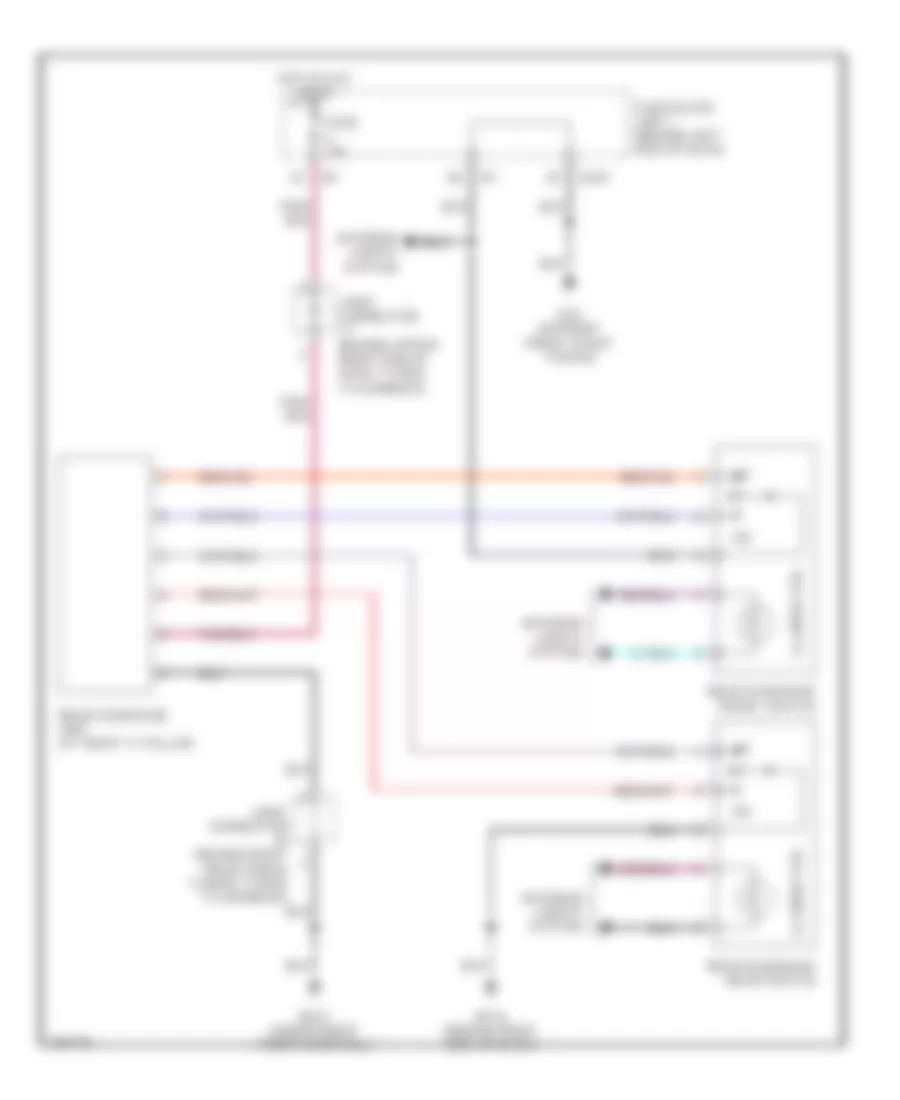
DEFOGGERS
Defoggers Wiring Diagram for Infiniti Q45 2004
List of elements for Defoggers Wiring Diagram for Infiniti Q45 2004:
- (at left "c" pillar) condenser
- (behind right side of dash) m114
- (behind upper right end of dash, taped to harness) joint connector 17
- 20b
- B17 (under left front door sill)
- B181
- B421
- B422 (at base of right "c" pillar)
- Body control module (bcm) (behind left kick panel)
- Combination meter
- Def sw
- Door mirror defogger relay (above fuse block (j/b) 1)
- Driver side door mirror defogger
- Fuse 1 10a
- Fuse 10 20a
- Fuse 11 20a
- Fuse 4 10a
- Fuse block (j/b) 1 (behind left end of dash)
- Gnd
- Grd
- Hot at all times
- Hot in acc or on
- Hot in on or start
- Ignition
- Joint connector 16 (behind upper right end of dash, taped to harness)
- Joint connector 2 (behind left side of dash, near fuse block)
- Joint connector 41 (in left front door)
- M114 (behind right side of dash)
- M24 (behind left side of dash)
- M42
- Multifunction switch
- Passenger side door mirror defogger
- Rear defog
- Rear window defogger
- Rear window defogger and door mirror defogger relay (above fuse block (j/b) 1)
- Rr def f/b
- Rr def on
- Unified meter ctrl unit
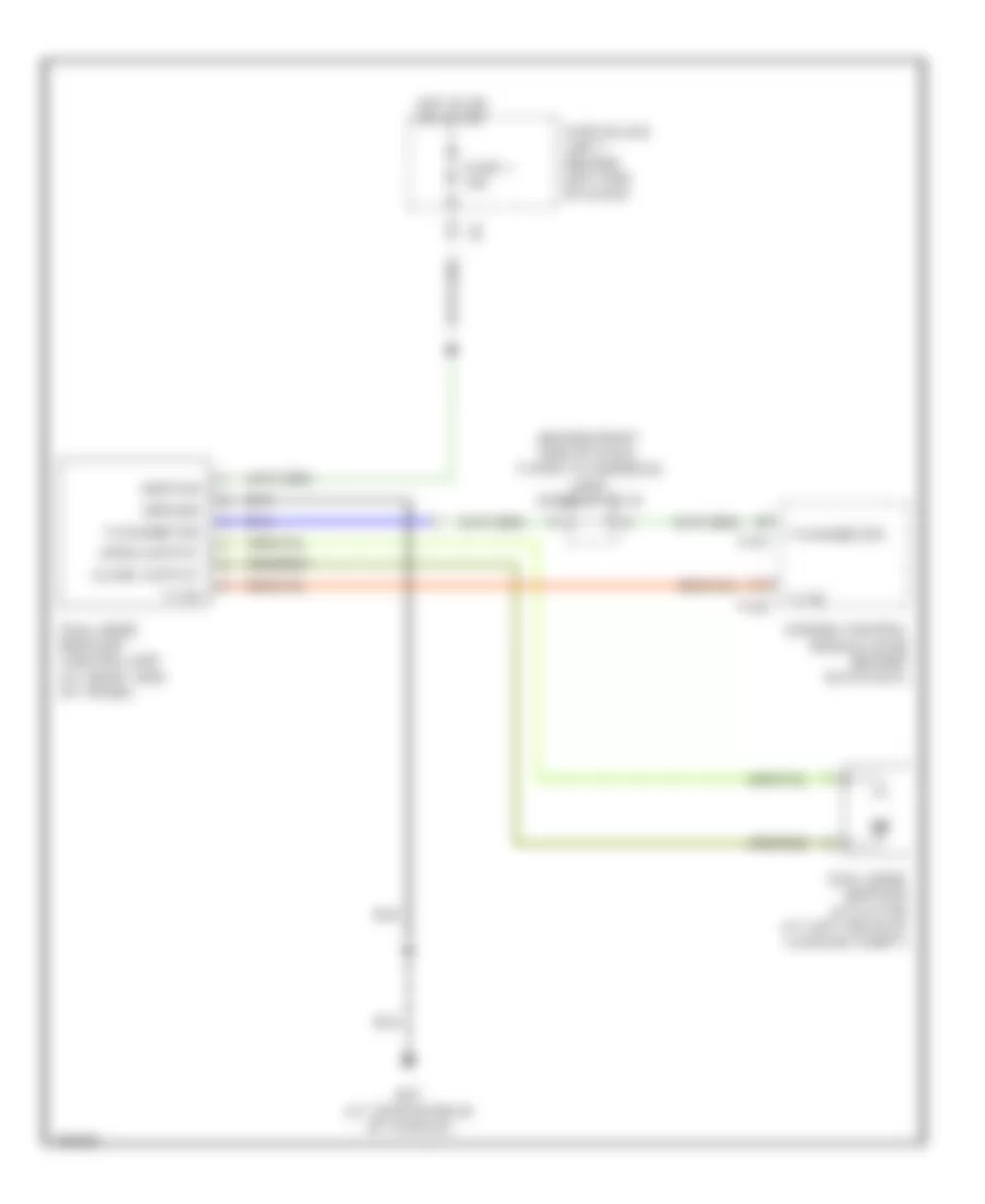
ELECTRONIC MUFFLER
Electronic Muffler Wiring Diagram for Infiniti Q45 2004
List of elements for Electronic Muffler Wiring Diagram for Infiniti Q45 2004:
- (behind right end of dash, taped to harness) joint connector 19
- B57 (at center rear of vehicle)
- Close output
- Dual mode muffler actuator (at left rear of luggage compt)
- Dual mode muffler control unit (at right side of trunk)
- Engine control module (ecm) (behind glove box)
- F101
- F102
- Fuse 1 10a
- Fuse block (j/b) 1 (behind left end of dash)
- Ground
- Hot in on or start
- Ignition
- Open output
- Tachometer
- Tvo0
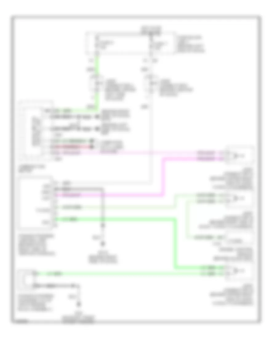
ELECTRONIC POWER STEERING
Electronic Power Steering Wiring Diagram for Infiniti Q45 2004
List of elements for Electronic Power Steering Wiring Diagram for Infiniti Q45 2004:
- (behind left side of dash) m24
- (behind right side of dash) m114
- Combination meter
- Computer data lines system
- E24 (on right front strut tower)
- Engine control module (behind glove box)
- F101
- Fuse 7 10a
- Fuse 9 10a
- Fuse block (j/b) 1 (behind left end of dash)
- Gnd
- Hot in on or start
- Ign
- Joint connector 16 (behind upper right end of dash, taped to harness)
- Joint connector 18 (behind upper right end of dash, taped to harness)
- Joint connector 19 (behind right end of dash, taped to harness)
- Joint connector 4 (behind upper left side of dash)
- Joint connector 9 (behind center of dash)
- M114 (behind right side of dash)
- M41
- M43
- Power steering control unit (behind dash, right side of center console)
- Power steering solenoid valve (on steering rack assembly)
- Sol
- Tacho
- Unified meter control unit
- Vsp
ELECTRONIC SUSPENSION
Electronic Suspension Wiring Diagram (1 of 2) for Infiniti Q45 2004
List of elements for Electronic Suspension Wiring Diagram (1 of 2) for Infiniti Q45 2004:
- (at center rear of vehicle) b57
- (behind left side of dash) m25
- Active damper suspension control unit (behind left rear shock tower)
- Active damper suspension select switch
- Actr lf b
- Auto
- B17 (under left front door sill)
- B37
- B38
- Batt
- Data link connector (under left side of dash)
- E24 (on right front strut tower)
- E62 (on left front fenderwell, near engine oil level gauge)
- Engine control module (behind glove box)
- Eps sol
- Exterior lights system
- F101
- Fr com actr
- Fuse 17 15a
- Fuse 6 10a
- Fuse 7 10a
- Fuse block (j/b) 1 (behind left end of dash)
- G sens fr in
- G sens gnd
- G sens pwr
- G sens rr in
- Gnd 1
- Gnd 2
- Gnd 3
- Hot at all times
- Hot in on or start
- Ign 2
- Ign 3
- Ign 4
- Illum
- Ind
- Interior lights system
- Joint connector (behind center of dash)
- Joint connector (behind upper right end of dash, taped to harness)
- Joint connector 11 (behind upper right side of dash, taped to harness)
- Joint connector 12 (behind top center of dash, taped to harness)
- Joint connector 19 (behind right end of dash, taped to harness)
- Joint connector 3 (behind upper left side of dash)
- Joint connector 5 (behind left side of dash, taped to harness)
- Left front shock absorber actuator (on top of left shock tower, under hood)
- Lf actr a
- Lf actr b
- Lr actr a
- Lr actr b
- Pnk
- Power steering control unit (behind dash, right side of center console)
- Power steering solenoid valve (on steering rack assembly)
- Red
- Rf actr a
- Rf actr b
- Right front shock absorber actuator (on top of right shock tower, under hood)
- Rr actr a
- Rr actr b
- Rr actr com
- Select
- Speed sens
- Sport
- Stop sw
- Stoplight switch (on bracket, above brake pedal)
- Strg sen 1
- Strg sen 2
- Strg sen neu
- Tacho
- Vign
Electronic Suspension Wiring Diagram (2 of 2) for Infiniti Q45 2004
List of elements for Electronic Suspension Wiring Diagram (2 of 2) for Infiniti Q45 2004:
- 12v
- Anti-lock brakes system
- B17 (under left front door sill)
- B217 (under right front door sill)
- Can-h
- Can-l
- Combination meter
- Computer data lines system
- Front vertical g sensor (at base of left kick panel)
- Fuse 9 10a
- Fuse block (j/b) 1 (behind left end of dash)
- Gnd
- Hot in on or start
- Joint connector (behind right rear shock tower, taped to harness)
- Joint connector 16 (behind upper right end of dash, taped to harness)
- Joint connector 4 (behind upper left side of of dash)
- Left rear shock absorber actuator (on top of left rear shock tower)
- M115 (behind right side of dash)
- M24 (behind left side of dash)
- M41
- M43
- Pnk
- Rear vertical g sensor (at right "c" pillar)
- Right rear shock absorber actuator (on top of right rear shock absorber)
- Sen 1
- Sen 2
- Sen 3
- Sport ind
- Steering angle sensor (at right side of steering column)
- Unified meter control unit
- Vcc
- Vout
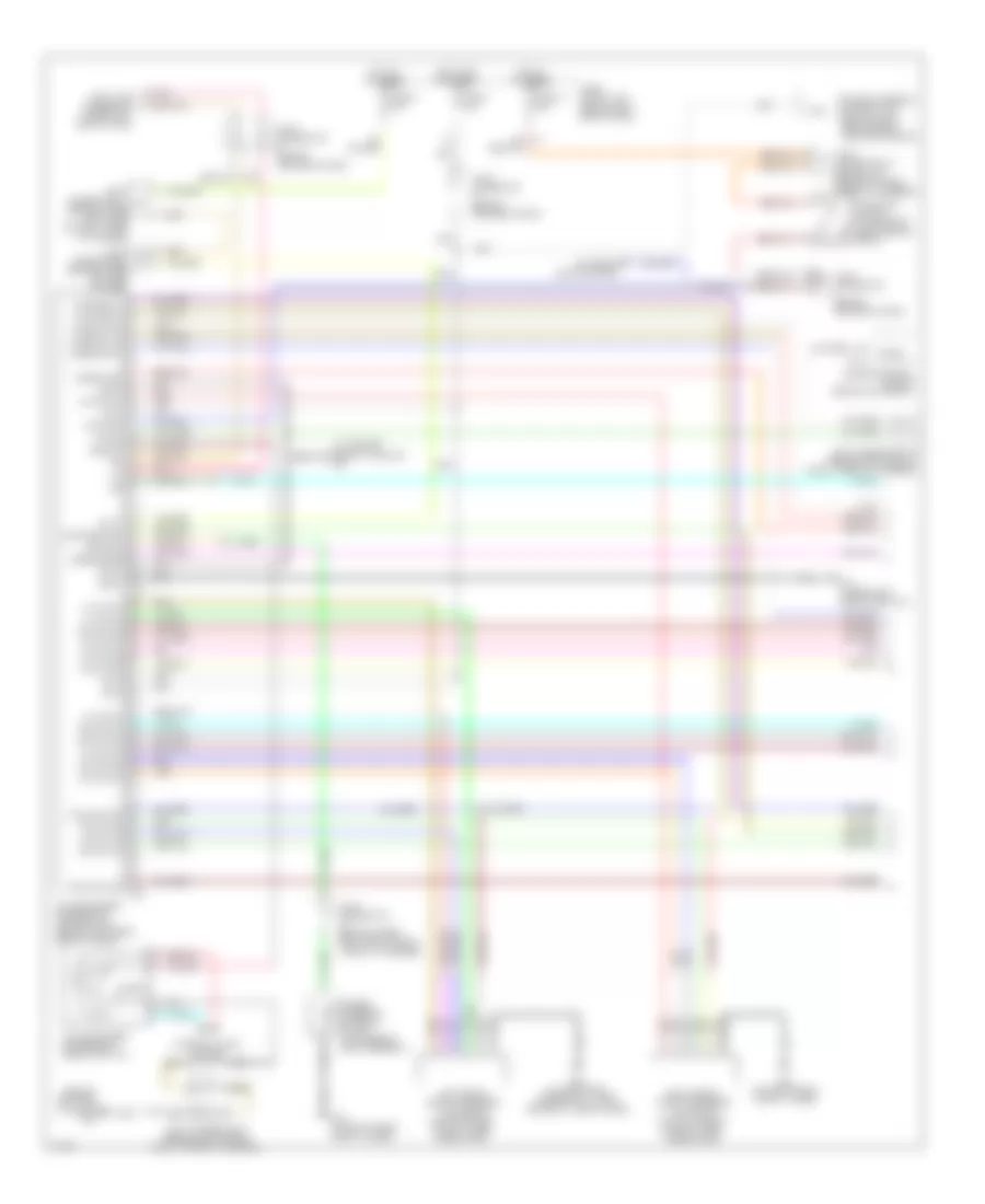
ENGINE PERFORMANCE
4.5L
4.5L, Engine Performance Wiring Diagram (1 of 5) for Infiniti Q45 2004
List of elements for 4.5L, Engine Performance Wiring Diagram (1 of 5) for Infiniti Q45 2004:
- (behind right kick panel)
- (behind upper left side of dash) j/c 4
- A/c system
- Acrly
- Active damper suspension unit control unit (left rear shock tower)
- Ascd control unit (behind dash, left of steering column)
- Combination meter
- Cooling fan speed control solenoid valve (on front of engine)
- Crankshaft position sensor (pos) (on rear of cyl block)
- Crtn
- Cvbv
- Dual mode muffler control unit (at right of trunk)
- Engine control module (ecm) (behind glove box)
- Etc prun
- Evap
- Evap canister purge volume control solenoid valve (on top right rear of engine)
- F8 (left front of eng comp, near eng oil level gauge)
- Fpcm
- Fpr
- Fuel injector
- Fuse 10a
- Fuse block (j/b) 1 (left end of panel)
- Hot in on or start
- Ign 1
- Ign 2
- Ign 3
- Ign 4
- Ign 5
- Ign 6
- Ign 7
- Ign 8
- Ignsw
- Inj 1
- Inj 2
- Inj 3
- Inj 4
- Inj 5
- Inj 6
- Inj 7
- Inj 8
- J/c (behind right kick panel)
- J/c 19 (behind right end of dash)
- J/c 28
- Led
- Malfunction indicator lamp
- Motrly
- Nca
- O2hfl
- O2hfr
- O2hrl
- O2hrr
- Pnk
- Pos
- Power steering control unit (behind dash, right side of center console)
- Prf+
- Prf-
- Prun in
- Red
- Ssoff
- Stsw
- Tacho
- Tp in
- Tvo0
- Unified meter control unit
- Vacuum cut valve bypass valve (under rear of vehicle, forward of evap canister)
- Vias
- Vias control solenoid valve (top front center of engine)
4.5L, Engine Performance Wiring Diagram (2 of 5) for Infiniti Q45 2004
List of elements for 4.5L, Engine Performance Wiring Diagram (2 of 5) for Infiniti Q45 2004:
- (behind right end of dash) j/c 19
- (left front of eng comp, near eng oil level gauge)
- 22r
- Condenser
- Ecm relay
- Fuse 10a
- Fuse 15a
- Fuse 20a
- Fuse block (j/b) 1 (left end of panel)
- Fuse block (j/b) 2 (right kick panel)
- Fuse, fusible link & relay block (j/b) (in engine room box)
- Hot at all times
- Hot in on or start
- Hot in start
- Ignition coil 1 (w/ power transistor)
- Ignition coil 2 (w/ power transistor)
- Ignition coil 3 (w/ power transistor)
- Ignition coil 4 (w/ power transistor)
- Ignition coil 5 (w/ power transistor)
- Ignition coil 6 (w/ power transistor)
- Ignition coil 7 (w/ power transistor)
- Ignition coil 8 (w/ power transistor)
- J/c 21 (behind lower right side of dash)
- Nca
- Plug spark
- Red
- Spark plug
- Throttle control motor relay
4.5L, Engine Performance Wiring Diagram (3 of 5) for Infiniti Q45 2004
List of elements for 4.5L, Engine Performance Wiring Diagram (3 of 5) for Infiniti Q45 2004:
- (behind top center of dash) j/c 12
- 33r
- 34r
- Camshaft position sensor (phase) (on front of left cyl head)
- F8 (left front of engine compt)
- Fuel pump relay
- Fuse 10a
- Fuse 15a
- Fuse block (j/b) 1 (left end of dash)
- Fuse block (j/b) 2 (right kick panel)
- Fuse, fusible link & relay block (j/b) (in engine room box)
- Heated oxygen sensor 1 (bank 1) (on inlet of left manifold three-way catalyst)
- Heated oxygen sensor 1 (bank 2) (on inlet of right manifold three-way catalyst)
- Heated oxygen sensor 2 (bank 1) (on outlet of left manifold three-way catalyst)
- Heated oxygen sensor 2 (bank 2) (on outlet of right manifold three-way catalyst)
- Hot at all times
- Hot in on or start
- Intake valve timing control position sensor (bank 1) (on front of left cyl head)
- Intake valve timing control position sensor (bank 2) (on front of right cyl head)
- J/c 29 (behind right kick panel)
- J/c 30
- Nca
- Panel)
- Radiator coolant temperature sensor (left side of radiator)
- Red
- Refrigerant pressure sensor (front right side of engine compt, near condenser)
4.5L, Engine Performance Wiring Diagram (4 of 5) for Infiniti Q45 2004
List of elements for 4.5L, Engine Performance Wiring Diagram (4 of 5) for Infiniti Q45 2004:
- (right kick panel) b217
- Accelerator pedal position (app) sensor 1
- Accelerator pedal position (app) sensor 2
- Aps1
- Avcc2
- Batt
- Condenser
- Electric throttle control actuator
- Engine control module (ecm) (behind glove box)
- Engine coolant temperature sensor (on top rear of engine)
- Evap control system pressure sensor (in evap purge line)
- F8 (left front of engine compt)
- F8 (left front of engine)
- Fuel pump control module (fpcm) (on right side of trunk)
- Gnd a
- Gnd a2
- Ivcpusl
- Ivcpusr
- J/c
- J/c (behind right kick panel)
- J/c 28 (behind right kick panel)
- J/c 29 (behind right kick panel)
- Mass airflow (maf) sensor (intake air temp sensor) (between air duct & air cleaner housing)
- Nca
- Neut
- Pdpres
- Phase
- Pnk
- Power steering pressure (psp) sensor (lower right front of engine)
- Qa+
- Red
- Starting/ charging system
- Throttle control motor
- Throttle position (tp) sensor 1
- Throttle position (tp) sensor 2
- Tps2
4.5L, Engine Performance Wiring Diagram (5 of 5) for Infiniti Q45 2004
List of elements for 4.5L, Engine Performance Wiring Diagram (5 of 5) for Infiniti Q45 2004:
- (left front of engine compt, near engine oil gauge)
- (left kick panel) b17
- Aps2
- Avcc
- Brksw
- Can h
- Can l
- Cdcv
- Computer data lines system
- Dropping resistor
- Engine control module (ecm) (behind glove box)
- Evap canister vent control valve (under rear of vehicle, on evap canister)
- Fgauge+
- Fgauge-
- Fpcmck
- Ftprs
- Fuel level sensor unit & fuel pump (in fuel tank)
- Gnd c
- Gnd e
- Gnd m
- Im lime
- Intake valve timing control solenoid valve (bank 1) (on top front of left cyl head)
- Intake valve timing control solenoid valve (bank 2) (on top front of right cyl head)
- Ivcl
- Ivcr
- J/c (behind right kick panel)
- J/c 15 (behind upper right side of dash)
- J/c 7 (behind center of dash)
- Kline
- Knk1
- Knk2
- Knock sensor (bank 1) (below left side of intake manifold)
- Knock sensor (bank 2) (below right side of intake manifold)
- Motor 1
- Motor 2
- Nats immu (behind dash, left of steering column)
- Nca
- O2sfl
- O2sfr
- O2srl
- O2srr
- Pnk
- Pspres
- Qa-
- Red
- Stop lamp switch (on bracket, above brake pedal)
- Tps1
- Tvo0
- Twrf
- Vmot
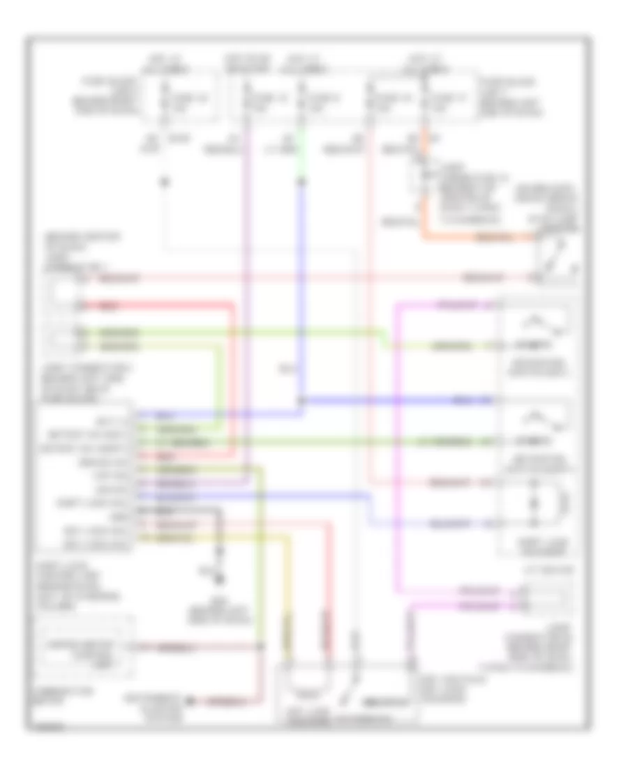
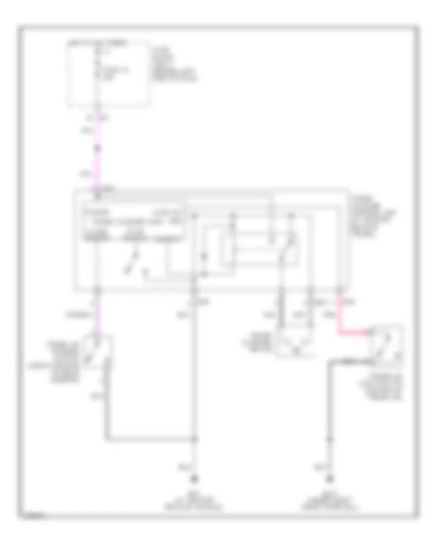
EXTERIOR LIGHTS
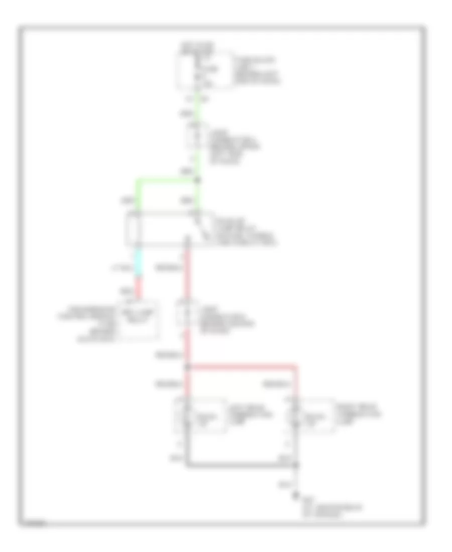
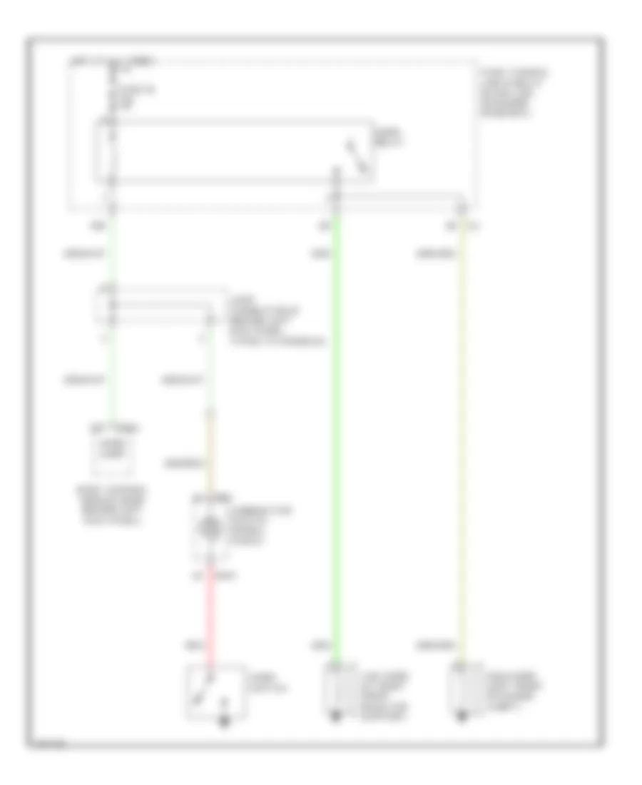
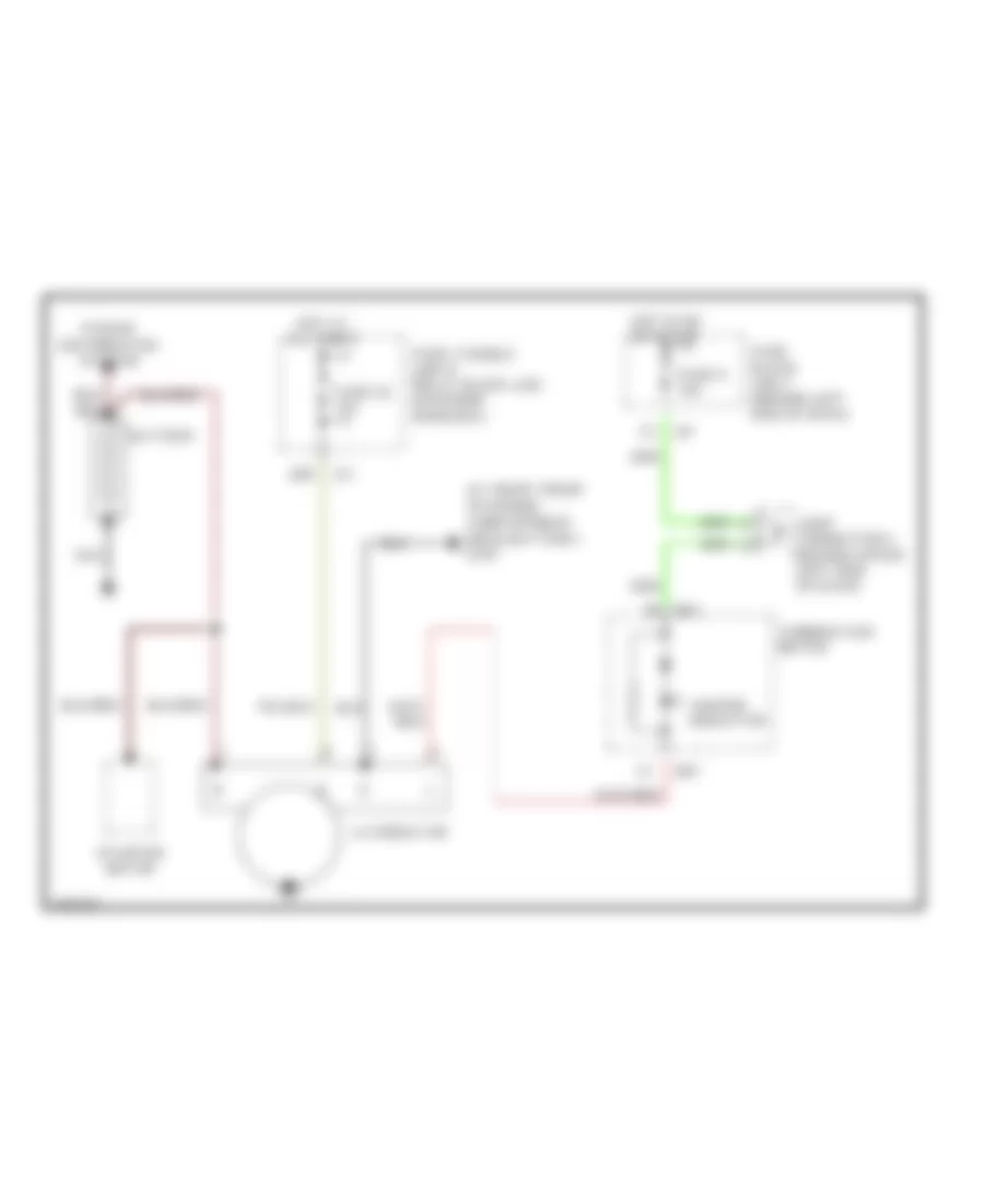
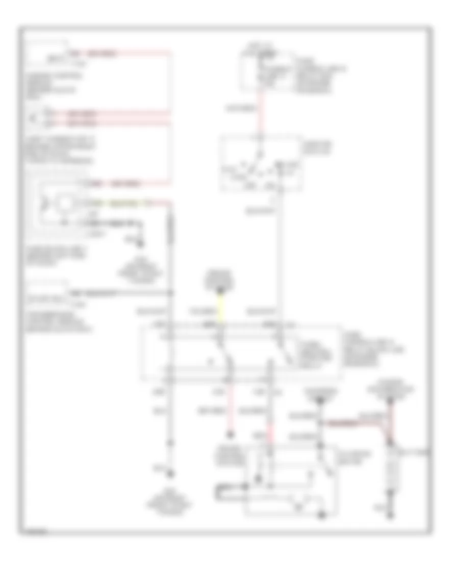
Back-up Lamps Wiring Diagram for Infiniti Q45 2004
List of elements for Back-up Lamps Wiring Diagram for Infiniti Q45 2004:
- B57 (at center rear of vehicle)
- Back- up
- Back-up lamp relay (in fuse, fusible link & relay box)
- Fuse 10a
- Fuse block (j/b) 1 (behind left end of dash)
- Hot in on or start
- Joint connector 4 (behind upper left side of dash)
- Joint connector 9 (behind center of dash)
- Left rear combination lamp
- Red
- Rev-lamp relay
- Right rear combination lamp
- Transmission control module (tcm) (behind glove box)
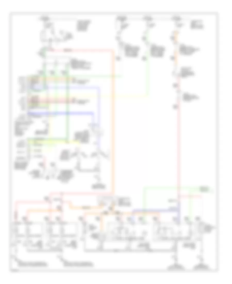
Exterior Lamps Wiring Diagram (1 of 2) for Infiniti Q45 2004
List of elements for Exterior Lamps Wiring Diagram (1 of 2) for Infiniti Q45 2004:
- 12r
- 1st
- 20b
- 26r
- 2nd
- Auto
- B217 (under right front door sill)
- B57 (at center rear of vehicle)
- Bat
- Body control module (bcm) (behind left kick panel)
- Comb sw
- Combi- nation switch (lighting switch)
- Door sw
- Driver side front door switch
- E201
- E42 (on right front fenderwell, forward of engine room box)
- E44 (on right front fenderwell, forward of engine room box)
- E45
- E46
- E65
- E66
- Fuse 1 10a
- Fuse 17 15a
- Fuse 54 15a
- Fuse 6 10a
- Fuse block (j/b) 1 (behind left end of dash)
- Fuse, fusible link & relay block (j/b) (in engine room box)
- Gnd
- H/l rly
- H/l sw
- Headlamp battery saver control unit (behind dash, left of steering column)
- Headlights system
- High- mounted stop lamp
- Hot at all times
- Hot in on or start
- Ign sw
- Joint connector 11 (behind upper right side of dash, taped to harness)
- Joint connector 12 (behind top center of dash, taped to harness)
- Joint connector 16 (behind upper right end of dash, taped to harness)
- Joint connector 18 (behind upper right end of dash, taped to harness)
- Joint connector 7 (behind center of dash)
- Left front combination lamp
- Left license lamp
- Left rear combination lamp
- M115 (behind right side of dash)
- M25 (behind left side of dash)
- M33
- M34
- Off
- Parking
- Passenger side front door switch (at base of right "b" pillar)
- Rap
- Rap out
- Right front combination lamp
- Right license lamp
- Right rear combination lamp
- Side marker
- Stop
- Stop light switch (on bracket, above brake pedal)
- T/l rly
- T/l sw
- Tail
- Tail lamp relay
- Turn
Exterior Lamps Wiring Diagram (2 of 2) for Infiniti Q45 2004
List of elements for Exterior Lamps Wiring Diagram (2 of 2) for Infiniti Q45 2004:
- (behind right side of dash, taped to harness) joint connector 20
- 10b
- 11b
- 17b
- 18b
- Bat
- Body control module (behind left kick panel)
- Combination flasher unit (behind dash, right side of center console)
- Combination meter (turn signal)
- Combination switch (turn signal switch)
- Driver side door mirror (turn signal)
- E201
- E62 (on left front fenderwell, near engine oil level gauge)
- Flasher
- Fuse 22 15a
- Fuse 5 10a
- Fuse block (j/b) 1 (behind left end of dash)
- Gnd
- Haz sw & bcm
- Hazard
- Hazard switch
- Hot at all times
- Hot in on or start
- Ign sw
- Illum
- Interior lights system
- Joint connector 11 (behind upper right side of dash, taped to harness)
- Joint connector 4 (behind upper left side of dash)
- Left front combination lamp (turn signal)
- Left turn
- Left turn ind
- Low tire pressure warning control unit (behind center of dash)
- M114 (behind right side of dash)
- M24 (behind left side of dash)
- M43
- Passenger side door mirror (turn signal)
- Pnk
- Right front combination lamp (turn signal)
- Right turn
- Right turn ind
- T/s sw
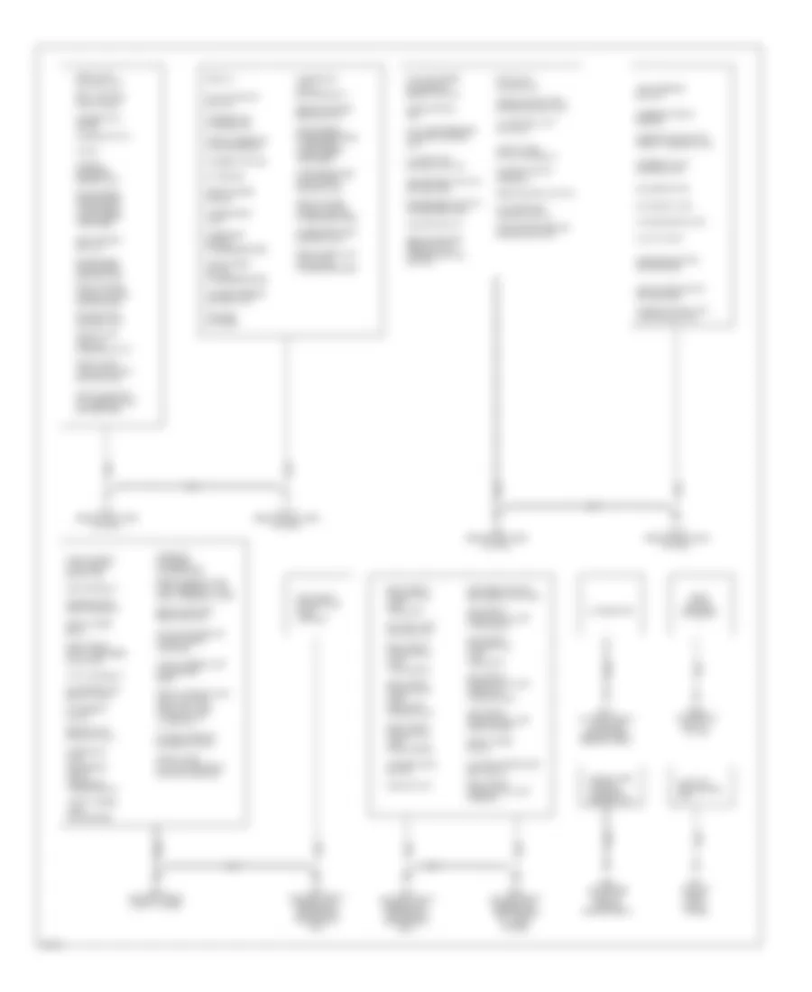
GROUND DISTRIBUTION
Ground Distribution Wiring Diagram (1 of 2) for Infiniti Q45 2004
List of elements for Ground Distribution Wiring Diagram (1 of 2) for Infiniti Q45 2004:
- A/c auto amp
- A/t device
- A/t pv ign relay
- Active damper suspension select switch
- Adp steering switch
- Air bag diagnosis sensor unit
- Air mix door motor (driver side)
- Air mix door motor (passenger side)
- Alternator
- Ascd control unit
- Auto anti-dazzling inside mirror -compass
- Auto return cancel switch
- Av control unit (w/o navi)
- B422 (at base of right "c" pillar)
- Blower motor
- Body control module (bcm)
- Brake fluid level switch
- Cd auto changer
- Climate controlled seat relay
- Clock
- Combination flasher unit
- Combination meter
- Combination switch (front wiper switch)
- Combination switch (lighting switch)
- Console box lamp
- Data link connector
- Daytime light control unit
- Display
- Door mirror (driver side) -turn signal -door mirror defogger
- Door mirror (passenger side) -turn signal -door mirror defogger
- Door mirror remote control switch
- Driver door control unit
- Driver side door mirror control unit
- E24 (on right front strut tower)
- E307 (at right front of engine compartment, near battery)
- E42 (on right front fenderwell, forward of engine room box)
- E44 (on right front fenderwell, forward of engine room box)
- E59 (at center front of engine compartment)
- E62 (on left front fenderwell, near engine oil level gauge)
- E67 (on left front strut tower)
- Front cigarette lighter socket
- Front door key cylinder switch (driver side)
- Front door lock actuator (driver side)
- Front door lock actuator (passenger side)
- Front interior lamp -left map lamp -right map lamp -interior lamp ill switch
- Front power socket
- Front power window motor (driver side)
- Front power window motor (passenger side)
- Front wiper motor
- Front wiper relay
- Fuse block (j/b) 1 -accessory relay -trunk lid opener relay
- Fuse block (j/b) 2 blower relay
- Fuse, fusible link & relay block (j/b)
- Glove box lamp
- Handset (option)
- Hazard switch
- Headlamp battery saver control unit
- Heated seat switch (driver side)
- Heated seat switch (passenger side)
- Homelink universal transceiver
- Hood switch
- Icc brake hold relay (w/icc)
- Icc sensor (w/icc)
- Ignition relay
- Illumination control switch
- Intake door motor
- Left front combination lamp -headlamp
- Left front combination lamp -headlamp aiming motor
- Left front combination lamp -parking
- Left front combination lamp -side marker
- Left front combination lamp -turn signal
- Left front shock absorber actuator
- Low tire pressure warning control unit
- M114 (behind right side of dash)
- M115 (behind right side of dash)
- M24 (behind left side of dash)
- M25 (behind left side of dash)
- Mode door motor (driver side)
- Mode door motor (passenger side)
- Multi-function switch
- Park/neutral position relay
- Passenger door control unit
- Passenger side door mirror control unit
- Power steering control unit
- Power steering solenoid valve
- Rear control switch
- Rear interior lamp -left personal lamp -right personal lamp
- Rear sunshade front switch
- Rear sunshade rear switch
- Rear sunshade rear switch (w/rear control switch)
- Rear window defogger (-)
- Right front combination lamp -headlamp
- Right front combination lamp -headlamp aiming motor
- Right front combination lamp -parking
- Right front combination lamp -side marker
- Right front combination lamp -turn signal
- Right front shock absorber actuator
- Seat memory switch
- Shield wire (a/t pv ign relay)
- Shield wire (air bag diagnosis sensor unit)
- Shield wire [tcm (transmission control module)]
- Shift lock control unit
- Steering angle sensor
- Steering lock control unit
- Sunroof motor assembly
- Trunk lid & fuel lid opener switch
- Vanity mirror lamp (driver side)
- Vanity mirror lamp (passenger side)
- Vdc off switch
- Vdc/tcs/ abs control unit
- Washer level switch
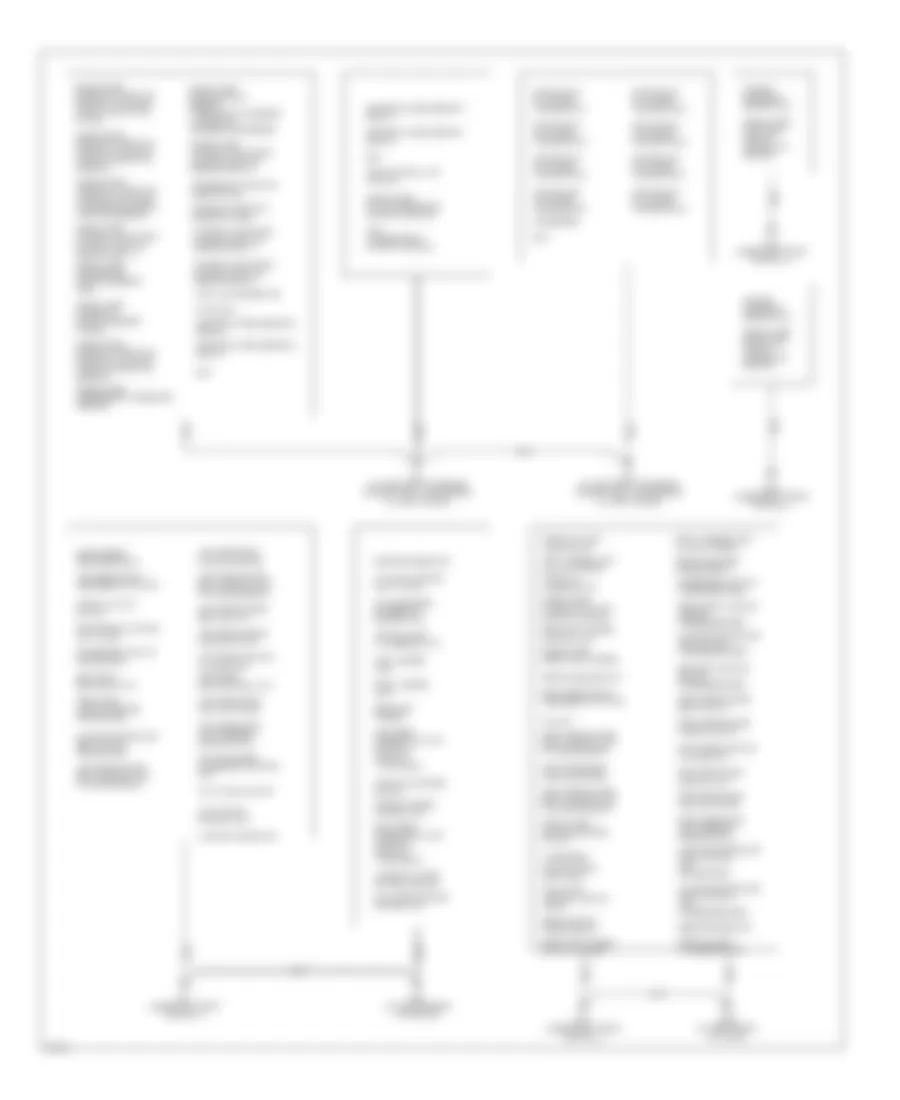
Ground Distribution Wiring Diagram (2 of 2) for Infiniti Q45 2004
List of elements for Ground Distribution Wiring Diagram (2 of 2) for Infiniti Q45 2004:
- Active damper suspension control unit
- Air bag diagnosis sensor unit
- Ascd control unit (w/o icc)
- Auto trunk control unit
- Auto trunk motor
- Av & navi control unit (w/ navi)
- B16 (under left front door sill)
- B17 (under left front door sill)
- B216 (under right front door sill)
- B217 (under right front door sill)
- B256 (at right front of trunk)
- B57 (at center rear of vehicle)
- Bose speaker amp
- Camshaft position sensor (phase)
- Climate controlled seat control unit (driver side)
- Climate controlled seat control unit (passenger side)
- Climate controlled seat switch (driver side)
- Climate controlled seat switch (passenger side)
- Condenser
- Crankshaft position sensor (pos)
- Data link connector
- Door mirror defogger relay
- Driver seat control unit (lcu02)
- Dropping resistor
- Dual mode muffler control unit
- Ecm
- F8 (at left front of engine compartment, near engine oil level gauge)
- F9 (at left front of engine compartment, near engine oil level gauge)
- Front seat cushion heater (driver side)
- Front seat cushion heater (passenger side)
- Fuel pump control module (fpcm)
- Heated oxygen sensor 1 (bank 1)
- Heated oxygen sensor 1 (bank 2)
- Heated oxygen sensor 2 (bank 1)
- Heated oxygen sensor 2 (bank 2)
- High-mounted stop lamp
- Icc unit
- Ignition coil (w/ power transistor) 1
- Ignition coil (w/ power transistor) 2
- Ignition coil (w/ power transistor) 3
- Ignition coil (w/ power transistor) 4
- Ignition coil (w/ power transistor) 5
- Ignition coil (w/ power transistor) 6
- Ignition coil (w/ power transistor) 7
- Ignition coil (w/ power transistor) 8
- Intake valve timing control position sensor (bank 1)
- Intake valve timing control position sensor (bank 2)
- Jumping connector
- Left license lamp
- Left license lamp (w/ auto trunk)
- Left rear ashtray illumination
- Left rear combination lamp -stop/tail -back-up -turn signal
- Left rear door control unit
- Left rear door lock actuator
- Left rear door lock assembly (door switch)
- Left rear power seat control unit (w/ heated seat)
- Left rear power seat control unit (w/o heated seat)
- Left rear power seat switch
- Left rear power window motor
- Left rear seat cushion heater
- Left rear shock absorber actuator
- Nats immu
- Power seat switch (driver side)
- Power seat switch (passenger side)
- Rear control cancel relay
- Rear sunshade cancel relay
- Rear sunshade unit
- Rear view camera
- Rear view camera (w/ auto trunk)
- Rear view camera control unit
- Right license lamp
- Right license lamp (w/ auto trunk)
- Right rear ashtray illumination
- Right rear combination lamp -stop/tail -back-up -turn signal
- Right rear door control unit
- Right rear door lock actuator
- Right rear door lock assembly (door switch)
- Right rear power seat control unit (w/ heated seat)
- Right rear power seat control unit (w/o heated seat)
- Right rear power seat switch
- Right rear power window motor
- Right rear seat cushion heater
- Right rear shock absorber actuator
- Seat belt buckle switch
- Seat belt buckle switch (passenger side)
- Shield wire (brake booster) (w/ icc)
- Shield wire (camshaft position sensor (phase)
- Shield wire (crankshaft position sensor (pos)
- Shield wire (electric throttle control actuator (accelerator pedal position sensor))
- Shield wire (electric throttle control actuator (throttle control motor))
- Shield wire (electric throttle control actuator (throttle position sensor))
- Shield wire (intake valve timing control position sensor (bank 1))
- Shield wire (intake valve timing control position sensor (bank 2))
- Shield wire (mass air flow sensor) - mass air flow sensor - intake air temperature sensor
- Shield wire (rear view camera)
- Shield wire (refrigerant pressure sensor)
- Shield wire (tcm (transmission control module))
- Shield wire (voice activation control module)
- Shield wire [left side air bag (satellite) sensor]
- Shield wire [right side air bag (satellite) sensor]
- Tcm (transmission control module)
- Trunk closure control unit
- Trunk lid close switch
- Trunk lid key cylinder switch
- Trunk lid lock lock switch
- Trunk lid lock switch
- Trunk lid striker switch
- Voice activated control module
HEADLIGHTS
Headlamps Wiring Diagram, with DRL (1 of 2) for Infiniti Q45 2004
List of elements for Headlamps Wiring Diagram, with DRL (1 of 2) for Infiniti Q45 2004:
- (behind center of dash)
- (behind right side of dash) m115
- (under left
- 1st
- 20b
- 2nd
- 6n m145
- Acc
- Auto
- Auto light sens
- Auto lt sens gnd
- Av & navi control unit
- Av control unit (behind center of dash)
- Av-me
- B29
- Bat
- Body control module (behind left kick panel)
- Comb sw (auto)
- Combination switch (lighting switch)
- Data link connector (under left side of dash)
- Door sw as
- Door sw dr
- Driver side front door switch
- Fuse 1 10a
- Fuse 21 10a
- Fuse 3 10a
- Fuse 32 10a
- Fuse 6 10a
- Fuse block (j/b) 1 (behind left end of dash)
- Fuse block (j/b) 2 (behind right kick panel)
- Gnd
- Gnd1
- Gnd2
- H/l rly out1
- H/l rly out2
- H/l sw1
- H/l sw2
- H/lamp rly
- Headlamp battery saver control unit (behind dash, left of steering column)
- Hot at all times
- Hot in acc or on
- Hot in on or start
- Ign
- Ign sw
- Iiurx
- Iiutx
- Ill out
- Interior lights system
- Joint connector 11 (behind upper right side of dash, taped to harness)
- Joint connector 16 (behind upper right end of dash, taped to harness)
- Joint connector 18 (behind upper right end of dash, taped to harness)
- Joint connector 20 (behind right side of dash, taped to harness)
- Joint connector 3 (behind upper left side of dash)
- Joint connector 7 (behind center of dash)
- Joint connector 8 (behind center of dash)
- Joint connector 9
- Joint connector 9 (behind center of dash)
- Key sw
- Key switch & key lock solenoid (key switch)
- Light sw (1st)
- Low
- M1 6c
- M24 (behind left side of dash)
- M25 (behind left side of dash)
- M33
- M34
- M77
- Meav
- Nca
- Off
- Optical sensor (on top right side of dash)
- Pass
- Pnk
- Rap input
- Rap output
- Shield
- Side of rear parcel shelf)
- T/l rly out 1
- T/l rly out2
- T/l sw1
- T/l sw2
- Tail/l rly
- W/ navigation
- W/o navigation
Headlamps Wiring Diagram, with DRL (2 of 2) for Infiniti Q45 2004
List of elements for Headlamps Wiring Diagram, with DRL (2 of 2) for Infiniti Q45 2004:
- 12r
- 13r
- 25r
- 26r
- Alt
- Alternator (right front of engine)
- Combination meter
- Daytime light control unit (left side of engine compt)
- E26
- E27
- E28
- E310
- E42 (on right front fenderwell, forward of engine room box)
- E45
- E46
- E62 (on left front fenderwell, near engine oil level gauge)
- E65
- E66
- Engine controls system
- Fuse 14 10a
- Fuse 54 15a
- Fuse 55 20a
- Fuse 57 20a
- Fuse 73 15a
- Fuse 82 10a
- Fuse block (at right side of engine compt)
- Fuse block (j/b) 1 (behind left end of dash)
- Fuse, fusible link & relay block (j/b) (in engine room box)
- Fuse, fusible link & relay box (in engine room box)
- Gnd
- Headlamp relay 1
- Headlamp relay 2
- Hid
- High
- High beam indicator
- Hot at all times
- Hot in on or start
- Hot in start
- Ign
- Joint connector 13 (behind top center of dash, taped to harness)
- Joint connector 17 (behind upper right end of dash, taped to harness)
- Joint connector 2 (behind left side of dash, near fuse block)
- Joint connector 20 (behind right side of dash, taped to harness)
- Left front combination lamp (headlamp)
- Lh light
- Lh light fuse
- Lh light main
- Lh main sw
- Low
- M42
- M43
- Parking brake switch (behind dash, at park brake assembly)
- Passenger side front door switch (at base of right "b" pillar)
- Pkb sw
- Pnk
- Red
- Rh light
- Rh light fuse
- Rh light main
- Rh main sw
- Right front combination lamp (headlamp)
- Start
- Starting/charging system
- Tail lamp relay
- Unified meter control unit
Headlamps Wiring Diagram, without DRL (1 of 2) for Infiniti Q45 2004
List of elements for Headlamps Wiring Diagram, without DRL (1 of 2) for Infiniti Q45 2004:
- (behind right side of dash) m115
- (under left
- 1st
- 20b
- 2nd
- 6n m145
- Acc
- Auto
- Auto light sens
- Auto lt sens gnd
- Av & navi control unit
- Av control unit (behind center of dash)
- Av-me
- B29
- Bat
- Body control module (behind left kick panel)
- Comb sw (auto)
- Combination switch (lighting switch)
- Data link connector (under left side of dash)
- Door sw as
- Door sw dr
- Driver side front door switch
- Fuse 1 10a
- Fuse 21 10a
- Fuse 3 10a
- Fuse 32 10a
- Fuse 6 10a
- Fuse block (j/b) 1 (behind left end of dash)
- Fuse block (j/b) 2 (behind right kick panel)
- Gnd
- Gnd1
- Gnd2
- H/l rly out1
- H/l rly out2
- H/l sw1
- H/l sw2
- H/lamp rly
- Headlamp battery saver control unit (behind dash, left of steering column)
- Hot at all times
- Hot in acc or on
- Hot in on or start
- Ign
- Ign sw
- Iiurx
- Iiutx
- Ill out
- Interior lights system
- Joint connector 11 (behind upper right side of dash, taped to harness)
- Joint connector 16 (behind upper right end of dash, taped to harness)
- Joint connector 18 (behind upper right end of dash, taped to harness)
- Joint connector 20 (behind right side of dash, taped to harness)
- Joint connector 3 (behind upper left side of dash)
- Joint connector 7 (behind center of dash)
- Joint connector 8 (behind center of dash)
- Joint connector 9 (behind center of dash)
- Key sw
- Key switch & key lock solenoid (key switch)
- Light sw (1st)
- Low
- M1 6c
- M24 (behind left side of dash)
- M25 (behind left side of dash)
- M33
- M34
- M77
- Meav
- Nca
- Off
- Optical sensor (on top right side of dash)
- Out
- Pass
- Pnk
- Power
- Rap input
- Rap output
- Shield
- Side of rear parcel shelf)
- T/l rly out 1
- T/l rly out2
- T/l sw1
- T/l sw2
- Tail/l rly
- W/ navigation
- W/o navigation
Headlamps Wiring Diagram, without DRL (2 of 2) for Infiniti Q45 2004
List of elements for Headlamps Wiring Diagram, without DRL (2 of 2) for Infiniti Q45 2004:
- 12r
- 13r
- 25r
- 26r
- Combination meter
- E201
- E42 (on right front fenderwell, forward of engine room box)
- E45
- E46
- E62 (on left front fenderwell, near engine oil level gauge)
- E65
- E66 left front combination lamp (headlamp)
- Fuse 54 15a
- Fuse 55 20a
- Fuse 57 20a
- Fuse 73 15a
- Fuse block (j/b) 1 (behind left end of dash)
- Fuse, fusible link & relay block (j/b) (in engine room box)
- Fuse, fusible link & relay box (in engine room box)
- Headlamp relay 1
- Headlamp relay 2
- Hid
- High
- High beam indicator
- Hot at all times
- Joint connector (behind left side of dash, near fuse block)
- Joint connector 13 (behind top center of dash, taped to harness)
- Joint connector 20 (behind right side of dash, taped to harness)
- Low
- M42
- M43
- Passenger side front door switch (at base of right "b"pillar)
- Pnk
- Red
- Right front combination lamp (headlamp)
- Tail lamp relay
- Unified meter control unit
HORN
Horn Wiring Diagram for Infiniti Q45 2004
List of elements for Horn Wiring Diagram for Infiniti Q45 2004:
- 19r
- Body control module (bcm) (behind left kick panel)
- Combination switch (spiral cable)
- E204
- Fuse 56 15a
- Fuse, fusible link & relay block (j/b) (in engine room box)
- High horn (left front of engine compt)
- Horn chrp
- Horn relay
- Horn switch
- Hot at all times
- Joint connector 25 (behind left kick panel, taped to harness)
- Low horn (at right front radiator support)
- M441
- M53
- Red
INSTRUMENT CLUSTER
Gauges & Indicators Wiring Diagram for Infiniti Q45 2004
List of elements for Gauges & Indicators Wiring Diagram for Infiniti Q45 2004:
- (at fuel tank) fuel level sensor unit & fuel pump
- (behind left side of dash) m24
- (behind right rear shock tower, taped to harness) joint connector 37
- (behind upper right end of dash, taped to harness) joint connector 15
- (on front center of engine) oil pressure switch
- (or red)
- (under left front door sill) b17
- (under right front door sill) b217
- (w/ icc/odo/trip meter & a/t indicator)
- +12v
- 15a
- A/t device
- A/t oil temp ind
- Abs ind
- Air bag ind
- Air conditioning system
- Anti-lock brakes system
- Auto
- Auto anti-dazzling inside mirror (compass)
- B17 (under left front door sill)
- Bat
- Belt ind
- Body control module (behind left kick panel)
- Brake fluid level switch (at left rear of engine compt, on brake fluid reservoir)
- Brake ind
- Charge ind
- Clock
- Combination meter
- Computer data lines system
- Cruise control system
- Cruise ind (w/o icc)
- Defogger system
- Diode
- Door ind
- Door sw (as)
- Door sw (dr)
- Door sw (rl)
- Door sw (rr)
- Door warn lamp
- Driver side front door switch
- Driver side front power seat
- E201
- E24 (on right front strut tower)
- Electroinc suspension system
- Electronic power steering system
- Engine control module (ecm) (behind glove box)
- Exterior lights system
- Fluorescent lamp
- Fuel fuel ind
- Fuel gauge
- Fuel level sensor
- Fuse 1 10a
- Fuse 21 10a
- Fuse 6 10a
- Fuse 9 10a
- Fuse block (j/b) 1 (behind left end of dash)
- Gnd
- Headlights system
- High beam ind
- Hot at all times
- Hot in acc or on
- Hot in on or start
- Illum
- Ind out
- Interior lights system
- Joint connector 11 (behind upper right side of dash, taped to harness)
- Joint connector 17 (behind upper right end of dash, taped to harness)
- Joint connector 3 (behind upper left side of dash)
- Joint connector 4 (behind upper left side of dash)
- Led
- Left rear door lock assembly (in left rear door)
- Left turn ind
- Light (+)
- Light (-)
- Low
- Low tire pressure warning control unit (behind center of dash)
- Low volt detection circuit
- M114 (behind right side of dash)
- M24 (behind left side of dash)
- M41
- M42
- M43
- Malfunction indicator lamp ind
- Manual
- Mode select switch
- Nca
- Oil ind
- Parking brake switch (behind dash, at park brake assembly)
- Passenger side front door switch (at base of right "b" pillar)
- Pnk
- Position select switch
- Red
- Right rear door lock assembly (in right rear door)
- Right turn ind
- Seat belt buckle switch
- Set ind (w/o icc)
- Slip ind
- Speedometer
- Sport ind
- Starting/ charging system
- Tachometer
- Tire pressure ind
- Unified meter control unit
- Vdc off ind
- Vehicle information system circuit
- W/ icc
- Water temp gauge
- Wiper/washer system
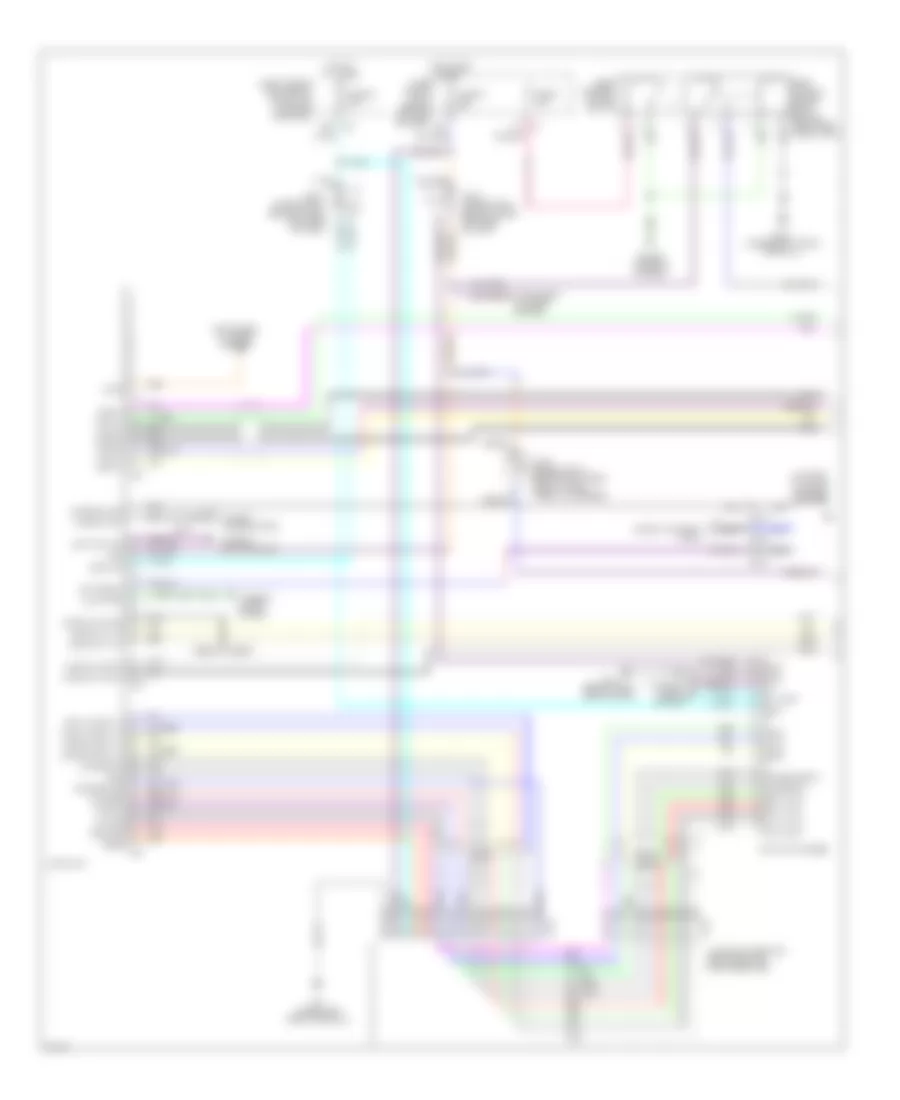
Vehicle Information System Wiring Diagram, with Navigation (1 of 2) for Infiniti Q45 2004
List of elements for Vehicle Information System Wiring Diagram, with Navigation (1 of 2) for Infiniti Q45 2004:
- (behind upper right end of dash, taped to harness) joint connector 17
- 23r e3
- Ac-av
- Acc
- Acclk
- Air conditioning system
- Av & navi control unit (under left side of rear parcel shelf)
- Av-ac
- Av-cn
- Av-me
- B29
- B30
- B57 (at center rear of vehicle)
- Bat
- Body control module (behind left kick panel)
- Bus (+)
- Bus (-)
- Bus shield
- Cn-av
- Combination meter
- Combination switch (spiral cable)
- Computer data lines system
- Data out
- Display
- Fuse 1 10a
- Fuse 15a
- Fuse 21 10a
- Fuse block (j/b) 1 (behind left end of dash)
- Fuse, fusible link & relay box (in engine room box)
- Gnd
- Hot at all times
- Hot in acc or on
- Hot in on or start
- Ign
- Iiurx
- Iiutx
- Ill out
- Joint connector 17 (behind upper right end of dash, taped to harness)
- Joint connector 3 (behind upper left side of dash)
- Joint connector 4 (behind upper left side of dash)
- Joint connector 7 (behind center of dash)
- Low tire pressure warning control unit (behind center of dash)
- M1 19b
- M114 (behind right side of dash)
- M41
- M441
- M53
- Me-av
- Multifunction switch
- Navigation system
- Nca
- Parking brake switch (behind dash, at park brake assembly)
- Pkb
- Pnk
- Red
- Rgb gnd
- Rgb sync
- Rx strg
- Shield
- Sound systems
- Speed
- Steering switch
- Tv +
- Tv -
- Tv sync
- Unified meter control unit
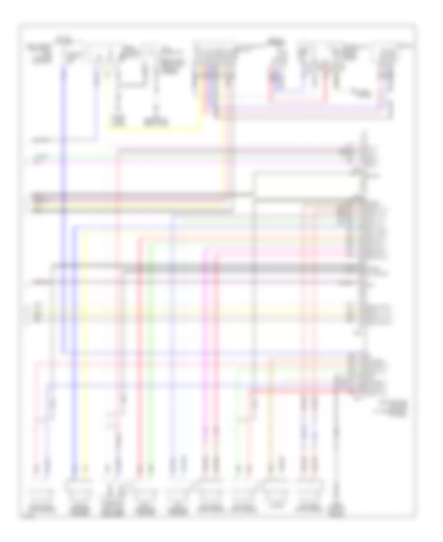
Vehicle Information System Wiring Diagram, with Navigation (2 of 2) for Infiniti Q45 2004
List of elements for Vehicle Information System Wiring Diagram, with Navigation (2 of 2) for Infiniti Q45 2004:
- (+)
- (-)
- (behind left side of dash, near fuse block) joint connector 10
- Acc
- Acp a
- Acp b
- Audio out (+)
- Audio out (-)
- Audio phn (+)
- Audio phn (-)
- Audio shield
- Audio unit
- B234
- B256 (at right front of trunk)
- B57 (at center rear of vehicle)
- B69
- B71
- Batt
- Bose speaker amplifier (at center front of trunk)
- Bus (+)
- Bus (-)
- Gnd
- Joint connector 36 (behind right rear shock tower, taped to harness)
- Joint connector 37 (behind right rear shock tower, taped to harness)
- M86
- M87
- Mic in (+)
- Mic in (-)
- Microphone (front of roof, under headliner)
- Mute
- Mute pse in
- Nca
- Option connector 2 for voice activated system
- Phn out (+)
- Phn out (-)
- Phn shield
- Phone (+)
- Phone (-)
- Pnk
- R10
- Red
- Shield
- Voice activated control module (left rear of trunk)
Vehicle Information System Wiring Diagram, without Navigation (1 of 2) for Infiniti Q45 2004
List of elements for Vehicle Information System Wiring Diagram, without Navigation (1 of 2) for Infiniti Q45 2004:
- (behind left side of dash) m25
- (behind left side of dash, taped to harness) joint connector 5
- (behind upper right end of dash, taped to harness) joint connector 17
- 19b m1
- 23r e3
- Ac-av
- Acc
- Acclk
- Air conditioning system
- Av control unit (behind center of dash)
- Av-ac
- Av-cn
- Av-me
- Bat
- Body control module (behind left kick panel)
- Bus (+)
- Bus (-)
- Bus shield
- Cn-av
- Combination meter
- Combination switch (spiral cable)
- Computer data lines system
- Data out
- Display
- Fuse 1 10a
- Fuse 15a
- Fuse 21 10a
- Fuse block (j/b) 1 (behind left end of dash)
- Fuse, fusible link & relay box (in engine room box)
- Gnd
- Hot at all times
- Hot in acc or on
- Hot in on or start
- Ign
- Iirux
- Iiutx
- Ill
- Ill out
- Joint connector 17 (behind upper right end of dash, taped to harness)
- Joint connector 3 (behind upper left side of dash)
- Joint connector 4 (behind upper left side of dash)
- Joint connector 7 (behind center of dash)
- Low tire pressure warning control unit (behind center of dash)
- M114 (behind right side of dash)
- M41
- M441
- M50
- M53
- M77
- M78
- Me-av
- Multifunction switch
- Navigation system
- Nca
- Parking brake switch (behind dash, at park brake assembly)
- Pkb
- Pnk
- Red
- Rgb gnd
- Rgb sync
- Rx strg
- Shield
- Sound systems
- Speed
- Steering switch
- Tv +
- Tv -
- Tv sync
- Unified meter control unit
Vehicle Information System Wiring Diagram, without Navigation (2 of 2) for Infiniti Q45 2004
List of elements for Vehicle Information System Wiring Diagram, without Navigation (2 of 2) for Infiniti Q45 2004:
- (+)
- (-)
- (behind left side of dash, near fuse block) joint connector 10
- Acc
- Acp a
- Acp b
- Audio out (+)
- Audio out (-)
- Audio phn (+)
- Audio phn (-)
- Audio shield
- Audio unit
- B234
- B256 (at right front of trunk)
- B57 (at center rear of vehicle)
- B69
- B71
- Batt
- Bose speaker amplifier (at center front of trunk)
- Bus (+)
- Bus (-)
- Gnd
- Joint connector (behind right rear shock tower, taped to harness)
- Joint connector 37 (behind right rear shock tower, taped to harness)
- M86
- M87
- Mic in (+)
- Mic in (-)
- Microphone (front of roof, under headliner)
- Mute
- Mute pse in
- Nca
- Option connector 2 for voice activated system
- Phn out (+)
- Phn out (-)
- Phn shield
- Phone (+)
- Phone (-)
- Pnk
- R10
- Red
- Shield
- Voice activated control module (left rear of trunk)
INTERIOR LIGHTS
Courtesy Lamps Wiring Diagram (1 of 2) for Infiniti Q45 2004
List of elements for Courtesy Lamps Wiring Diagram (1 of 2) for Infiniti Q45 2004:
- (behind left side of dash, near fuse block) joint connector 2
- (behind top center of dash, taped to harness) joint connector 13
- (on right front strut tower) e24
- 10k
- 12r
- 1st
- 20b
- 26r
- 2nd
- Acc
- All off
- Auto
- B57 (at center rear of vehicle)
- Bat
- Body control module (bcm) (behind left kick panel)
- Combination switch
- Computer data lines system
- D/mirror lamp
- Data line
- Door mirror lamp (driver side) (foot well)
- Door mirror lamp (passenger side) (foot well)
- Door sw (as)
- Door sw (dr)
- Door sw (rl)
- Door sw (rr)
- Driver front door switch
- E201
- Full
- Fuse 1 10a
- Fuse 10a
- Fuse 54 15a
- Fuse 6 10a
- Fuse 8 10a
- Fuse block (j/b) 1 (behind left end of dash)
- Fuse block (j/b) 2 (behind right kick panel)
- Fuse, fusible link & relay block (j/b) (in engine room box)
- Gnd
- Gnd1
- Gnd2
- Half
- Headlamp battery saver control unit (behind dash, left of steering column)
- Hot at all times
- Hot at all times
- Hot in on or start
- Ign
- Ign key ill
- Ign sw
- Ignition key hole illumination
- Iiurx
- Iutx
- Joint connector (behind upper right end of dash, taped to harness)
- Joint connector 11 (behind upper right side of dash, taped to harness)
- Joint connector 15 (behind upper right end of dash, taped to harness)
- Joint connector 16 (behind upper right end of dash, taped to harness)
- Joint connector 18 (behind upper right end of of dash, taped to harness)
- Joint connector 20 (behind right side of dash, taped to harness)
- Key sw
- Key switch & key lock solenoid (key switch)
- Left personal lamp
- Light sw (1st)
- M115 (behind right side of dash)
- M24 (behind left side of dash)
- M25 (behind left side of dash)
- M33
- M34
- M55
- Map/l (lh)
- Map/l (rh)
- Navigation system
- Off
- Personal lamp (rl)
- Personal lamp (rr)
- Personal lamp sw
- Rear interior lamp
- Right front door switch
- Right personal lamp
- T/l rly out1
- T/l rly out2
- T/l sw1
- T/l sw2
- Tail/l rly
- Taillamp relay
- Total ill
- Trunk lid striker switch (above center of rear bumper)
- Trunk room lamp
- Trunk, tailgate, fuel doors system
Courtesy Lamps Wiring Diagram (2 of 2) for Infiniti Q45 2004
List of elements for Courtesy Lamps Wiring Diagram (2 of 2) for Infiniti Q45 2004:
- (in left front door)
- Auto
- B17 (under left front door sill)
- B217 (under right front door sill)
- Bat (c/b)
- Circuit breaker
- Console lamp
- D38
- D39
- D58
- D59
- D78
- D79
- Data line a3
- Driver door control unit (in driver's door)
- Driver front door lock actuator (door unlock sensor) (in driver's door)
- Driver front step lamp
- E201
- E24 (on right front strut tower)
- Front interior lamp
- Fuse 21 10a
- Fuse 3 10a
- Fuse block (j/b) 1 (behind left end of dash)
- Gnd
- Hot at all times
- Hot in acc or on
- Illumination lamps circuit
- Interior lamp illumination switch
- Joint connector
- Joint connector (behind center of dash)
- Joint connector (behind center of dash)
- Joint connector (behind lower right end of dash, taped to harness)
- Joint connector (behind upper left side of dash)
- Joint connector 15 (behind upper right end of dash, taped to harness)
- Joint connector 37 (behind right rear shock tower, taped to harness)
- Left map light
- Left rear door control unit (in left rear door)
- Left rear door lock assembly (door switch) (in left rear door)
- Left rear step lamp
- Local data line
- Locked
- M114 (behind right side of dash)
- M24 (behind left side of dash)
- Off
- Passenger door control unit (in front passenger's door)
- Passenger front step lamp
- Red
- Right map light
- Right rear door control unit (in right rear door)
- Right rear door lock assembly (door switch) (in right rear door)
- Right rear step lamp
- Step/l
- Unlock sens
- Unlocked
- Vanity mirror lamp (driver side)
- Vanity mirror lamp (passenger side)
Instrument Illumination Wiring Diagram (1 of 3) for Infiniti Q45 2004
List of elements for Instrument Illumination Wiring Diagram (1 of 3) for Infiniti Q45 2004:
- (behind left kick panel) body control module
- (behind upper right end of dash, taped to harness) joint connector 16
- 10k
- 12r
- 1st
- 20b
- 26r
- 2nd
- Auto
- Auto return cancel switch (illum) (w/ rear control switch)
- Bat
- Comb sw (auto)
- Combination meter
- Combination switch (light switch)
- Computer data lines system
- Console box lamp
- Console lamp
- Courtesy lamps circuit
- Diode
- Door sw (as)
- Door sw (dr)
- Driver front door switch
- E201
- Exterior lights system
- Fluorescent lamp
- Front interior lamp
- Fuse 1 10a
- Fuse 54 15a
- Fuse 6 10a
- Fuse 8 10a
- Fuse 9 10a
- Fuse block (j/b) 1 (behind left end of dash)
- Fuse, fusible link & relay block (in engine room box)
- Gnd1
- Gnd2
- Headlamp battery saver control unit (behind dash, left of steering column)
- Hot at all times
- Hot in on or start
- Ign sw
- Ill out
- Joint connector 11 (behind upper right side of dash, taped to harness)
- Joint connector 16 (behind upper right end of dash, taped to harness)
- Joint connector 17 (behind upper right end of dash, taped to harness)
- Joint connector 18 (behind upper right end of dash, taped to harness)
- Joint connector 4 (behind upper left side of dash)
- Joint connector 5 (behind left side of dash, taped to harness)
- Light sw (1st)
- M114 (behind right side of dash)
- M115 (behind right side of dash)
- M24 (behind left side of dash)
- M25 (behind left side of dash)
- M33
- M34
- M41
- M42
- M43
- M55
- Off
- Power tops system
- Power windows system
- Rap input
- Rap output
- Rear control switch (illum) (w/ rear control switch)
- Rear sunshade rear switch (illum)
- Right front door switch
- T/l rly out 1
- T/l rly out 2
- T/l sw 1
- T/l sw 2
- Taillamp relay
- Tal/l rly
- Unified meter control unit
- W/ rear control switch
- W/o rear control switch
Instrument Illumination Wiring Diagram (2 of 3) for Infiniti Q45 2004
List of elements for Instrument Illumination Wiring Diagram (2 of 3) for Infiniti Q45 2004:
- (behind right side of dash) m114
- (behind right side of dash) m115
- (behind top center of dash, taped to harness)
- A/t device (illum)
- Active damper suspension select switch (illum)
- Ashtray
- Audio unit (illum)
- Cigarette lighter socket
- Clock (illum)
- Driver side heated seat switch (illum)
- Front cigarette lighter (illum)
- Glove box lamp
- Hazard switch (illum)
- Headlamp aiming switch (illum)
- Joint connector 1 (behind left side of dash, near fuse block)
- Joint connector 13
- Joint connector 2 (behind left side of dash, near fuse block)
- Multifunction switch (illum)
- Passenger side heated seat switch (illum)
- Rear sunshade cancel relay (w/ rear control unit) (behind right rear wheel well)
- Vdc off switch (illum)
- W/o rear control unit
Instrument Illumination Wiring Diagram (3 of 3) for Infiniti Q45 2004
List of elements for Instrument Illumination Wiring Diagram (3 of 3) for Infiniti Q45 2004:
- B17 (under left front door sill)
- B217 (under right front door sill)
- Cd auto changer (illum)
- Climate controlled seat switch (illum)
- Climate controlled seat temperature dial (illum)
- Door lock & unlock switch
- Door lock/ unlock switch
- Driver door control unit (in driver's door)
- Driver side front power seat
- Front power window sub auto switch
- Front rear sunshade switch (illum)
- Front window main auto sw
- Ill
- Ill cont
- Illumination control switch
- Joint connector 5 (behind left side of dash, taped to harness)
- L1a
- L2a
- Left rear ashtray (illumination)
- Left rear power seat switch (illum)
- M25 (behind left side of dash)
- Passenger door control unit (illum)
- Passenger side front power seat
- Power window main switch (illum)
- Rear control cancel switch (w/ rear control switch)
- Red
- Right rear ashtray (illumination)
- Right rear power seat switch (illum)
MEMORY SYSTEMS
Memory Systems Wiring Diagram (1 of 3) for Infiniti Q45 2004
List of elements for Memory Systems Wiring Diagram (1 of 3) for Infiniti Q45 2004:
- (behind left side of dash)
- (behind left side of dash) m24
- 20b
- A/d batt
- A/d gnd
- A/t device (detention switch (key))
- Acc
- Adp steering switch
- Back
- Batt
- Bcm (behind left kick panel)
- Circuit breaker 1
- Circuit breaker 2
- Computer data lines system
- Data line 3
- Data line a1
- Data line a2
- Detent switch
- Door sw
- Exterior lights system
- For
- Front door switch (driver side)
- Fuse 10a
- Fuse block (j/b) 1 (behind left end of dash)
- Fuse block (j/b) 2 (behind right kick panel)
- Gnd
- Hot at all times
- Hot in acc or on
- Hot in on or start
- Hot in start
- Ign
- Instrument cluster system
- Iurx
- Iutx
- Joint connector
- Joint connector (behind upper left side of dash)
- Joint connector (behind upper right end of dash, taped to harness)
- Joint connector (in left front door)
- Joint connector 16 (behind upper right end of dash, taped to harness)
- Joint connector 2 (behind left side of dash, near fuse block)
- Joint connector 6 (behind center of dash)
- Joint connector 9 (behind center of dash)
- Key switch
- Key switch & key lock solenoid (key switch)
- M145
- M24
- M25 (behind left side of dash)
- Mem 1
- Mem 1 sw
- Mem 2
- Mem 2 sw
- Mirror sw down
- Mirror sw left
- Mirror sw right
- Mirror sw up
- Pnk
- Red
- Rev lamp sw
- Seat memory switch
- Select sw left
- Select sw right
- Set sw
- Tele motor
- Tele signal
- Tele sw (fr)
- Tele sw (rr)
- Tele switch
- Telescopic motor (at right side of steering column)
- Telescopic sensor (at right side of steering column)
- Tilt motor
- Tilt motor (at right side of steering column)
- Tilt sens
- Tilt sensor (at right side of steering column)
- Tilt sw dwn
- Tilt sw up
- Tilt switch
- Tilt/tele 5v
- Vsp
Memory Systems Wiring Diagram (2 of 3) for Infiniti Q45 2004
List of elements for Memory Systems Wiring Diagram (2 of 3) for Infiniti Q45 2004:
- (behind left side of dash) m24
- (behind left side of dash) m25
- (behind right side of dash) m114
- Bat
- Change- over switch
- Computer data lines system
- Data line a2
- Data line a3
- Door mirror remote control switch
- Down
- Driver side door mirror actuator
- Driver side door mirror control unit (in driver's door)
- Gnd
- Interior lights system
- Joint connector (behind upper right end of dash, taped to harness)
- Joint connector 15 (behind upper right end of dash, taped to harness)
- Joint connector 17 (behind upper right end of dash, taped to harness)
- Joint connector 18 (behind upper right end of dash, taped to harness)
- Joint connector 19 (behind right end of dash, taped to harness)
- Joint connector 20 (behind right side of dash, taped to harness)
- Joint connector 41 (in left front door)
- Joint connector 5 (behind left side of dash, taped to harness)
- Left
- Mirror motor
- Mirror sens (left/right)
- Mirror sens (up/down)
- Mirror switch
- Motor (left/right)
- Motor (up/down)
- Passenger side door mirror actuator
- Passengers side door mirror control unit (in front passenger's door)
- Pnk
- Red
- Right
- Sensor (left/right)
- Sensor gnd
- Sensor power
- Sensor pwr
Memory Systems Wiring Diagram (3 of 3) for Infiniti Q45 2004
List of elements for Memory Systems Wiring Diagram (3 of 3) for Infiniti Q45 2004:
- 14a
- 15b
- 16a
- 32a
- 32b
- 32c
- B142
- B143
- B162
- B17 (under left front door sill)
- Back
- Bat
- Batt
- Bwd
- Data line a1
- Down
- Driver side power seat switch
- Driver side sliding motor
- Driver's seat control unit (under driver's seat)
- Driver's side reclining motor
- For
- Front lifting motor (driver side)
- Frt lift dwn
- Frt lift up
- Frt pulse sw
- Frt reclin mtr
- Frt reclin sw
- Frt slide mtr
- Frt slide sw
- Fwd
- Gnd
- Left rear power seat
- Left rear power seat control unit
- Lifting sensor
- Lumbar support motor
- Pnk
- Pulse sw gnd
- Rear lifting motor (driver side)
- Reclin puls sw
- Recline switch
- Red
- Rr lft up
- Rr lift dwn
- Rr lift up
- Rr pulse sw
- Rr reclin mtr
- Rr reclin sw
- Rr slide mtr
- Rr slide sw
- Slide pulse sw
- Slide switch
- Switch frt lift dn
- Switch lumbar
- Switch rear lift dn
NAVIGATION
Navigation Wiring Diagram (1 of 2) for Infiniti Q45 2004
List of elements for Navigation Wiring Diagram (1 of 2) for Infiniti Q45 2004:
- (not used pins are not shown)
- 12r
- 17d
- 19b
- 19d
- 20b
- 23r
- 26r
- A/c auto amplifier (behind right side of dash)
- A/c-av (fr tx)
- Ac-av
- Acc
- Acclk
- Av & navi control unit (under left side of rear parcel shelf)
- Av-a/c (fr rx)
- Av-ac
- Av-cn
- Av-me
- B188
- B231
- B233
- B234
- B29
- B30
- B57 (at center rear of vehicle)
- Bat
- Bose speaker amplifier (at center front of trunk)
- Bus shield
- Bus+
- Bus-
- Clk (fr)
- Cn-av
- Comm sig +
- Comm sig -
- Display
- E201
- E24 (on right front strut tower)
- Exterior lights system
- Fr-sp lh +
- Fr-sp lh -
- Fuse 10a
- Fuse 15a
- Fuse block (j/b) 1 (behind left end of dash)
- Fuse, fusible link & relay block (j/b) (in engine room box)
- Gnd
- Gps ant gnd
- Gps antenna
- Gps sig
- Hot at all times
- Hot in acc or on
- Hot in on or start
- Ign
- Ill
- Instrument cluster system (voice activated control module)
- Joint connector 12 (behind top center of dash, taped to harness)
- Joint connector 3 (behind upper left side of dash)
- Joint connector 4 (behind upper left side of dash)
- Left front door speaker
- M114 (behind right side of dash)
- M119
- Me-av
- Multi- function switch
- Navi +
- Navi -
- Nca
- Pkb
- Pnk
- Red
- Rgb gnd
- Rgb sync
- Shield
- Solid state
- Sound systems
- Speed
- Tail lamp relay
- Voice +
- Voice -
Navigation Wiring Diagram (2 of 2) for Infiniti Q45 2004
List of elements for Navigation Wiring Diagram (2 of 2) for Infiniti Q45 2004:
- (behind center of dash) joint connector 7
- (behind right side of dash) m115
- 1st
- 2nd
- Auto
- Backup lamp relay
- Bat
- Body control module (bcm) (behind left kick panel)
- Comb sw
- Combination meter
- Combination switch (lighting switch)
- Computer data lines system
- Data link connector (under left side of dash)
- Engine control module (ecm) (behind glove box)
- Exterior lights system
- F101
- F104
- Fuse, fusible link & relay block (j/b) (in engine room box)
- Gnd1
- Gnd2
- Headlamp battery saver control uint (behind dash, left of steering column)
- Ign sw
- Iiurx
- Iiutx
- Ill out
- Joint connector 11 (behind upper right side of dash, taped to harness)
- Joint connector 16 (behind upper right end of dash, taped to harness)
- Joint connector 17 (behind upper right end of dash, taped to harness)
- Joint connector 18 (behind upper right end of dash, taped to harness)
- Joint connector 3 (behind upper left side of dash)
- Joint connector 8 (behind center of dash)
- Joint connector 9 (behind center of dash)
- M24 (behind left side of dash)
- M25 (behind left side of dash)
- M33
- M34
- M41
- M43
- M55
- Nca
- Neut
- Off
- Parking brake switch (behind dash, at park brake assembly)
- Pnk
- Rap input
- Rap output
- Red
- Rev lamp rly
- Start rly
- Starting/ charging system
- T/l rly out1
- T/l rly out2
- T/l sw1
- T/l sw2
- Tail/l rly
- Transmission control module (tcm) (behind glove box)
- Unified meter control unit
Rear Camera Wiring Diagram for Infiniti Q45 2004
List of elements for Rear Camera Wiring Diagram for Infiniti Q45 2004:
- (in engine room box)
- 23r
- Acc
- B217 (under right front door sill)
- B57 (at center rear of vehicle)
- Back up
- Back-up lamp relay (in fuse, fusible link & relay box)
- Bose speaker amplifier (at center front of trunk)
- Bus(+)
- Bus(-)
- Camera
- Camera on
- Camera+
- Camera-
- Compo sync
- Compo+
- Compo-
- Display
- Exterior lights system
- Fuse 10a
- Fuse 15a
- Fuse block (j/b) 1 (behind left end of dash)
- Fuse, fusible link & relay box (j/b)
- Gnd
- Hot at all times
- Hot in acc or on
- Hot in on or start
- Iris
- Iris sw
- Joint connector 36 (behind right
- Joint connector 37 (behind right rear shock tower, taped to harness)
- Joint connector 4 (behind upper left side of dash)
- Joint connector 9 (behind center of dash)
- Nca
- Rear shock tower,
- Rear view camera (at deck lid)
- Rear view camera control unit (at center front of trunk)
- Reverse
- Shield
- Sig+
- Sig-
- Sync
- Taped to harness)
- Tv+
- Tv-
POWER DISTRIBUTION
Power Distribution Wiring Diagram (1 of 3) for Infiniti Q45 2004
List of elements for Power Distribution Wiring Diagram (1 of 3) for Infiniti Q45 2004:
- 16r
- 20r
- 22r
- 23r
- 27r
- 28r
- 29r
- 33r
- 34r
- Air condi- tioner relay
- Air conditioning system
- Anti-lock brakes system
- B201
- Battery
- Blower relay
- Cruise control system
- E215
- E24 (on right front strut tower)
- Ecm relay
- Engine control, computer data lines & transmissions systems
- Engine controls system
- Engine controls, transmissions, shift interlock & anti-theft systems
- From fuse 13 (diagram 2 of 3)
- From ignition switch (diagram 2 of 3)
- Fuel pump relay
- Fuse 10a
- Fuse 15a
- Fuse 20a
- Fuse block (j/b) 2 (behind right kick panel)
- Fuse, fusible link & relay block (j/b) (in engine room box)
- Fuse, fusible link & relay box (in engine room box)
- Fusible link b 50a
- Fusible link c 50a
- Fusible link f 30a
- Fusible link g 50a
- Fusible link h 40a
- Fusible link j 30a
- Fusible link k 50a
- Fusible link l 50a
- Headlamp relay 1
- Headlamp relay 2
- Horn relay
- Ignition relay
- M114 (behind right side of dash)
- M143
- M144
- M145
- Nca
- Phone handset
- Pnk
- Red
- Seats system
- Sound & navigation systems
- Sound systems
- Starting/ charging system
- Tail lamp relay
- Throttle control motor relay
- To fuse (diagram 2 of 3)
- To fuse block (j/b) 1 (diagram 2 of 3)
- To fuse block (j/b) 1 (diagram 3 of 3)
- To fuse block 1 (diagram 2 of 3)
- To ignition switch (diagram 2 of 3)
- Transmissions system
- Wiper/ washer system
Power Distribution Wiring Diagram (2 of 3) for Infiniti Q45 2004
List of elements for Power Distribution Wiring Diagram (2 of 3) for Infiniti Q45 2004:
- (at right side of engine comp)
- 10a
- 10c
- 19b
- 20b
- Acc
- Accessory relay
- Air conditioning system
- Air conditioning, defogger, power tops, interior lights, sound systems & phone handset
- Circuit breaker
- Cruise control systems
- E201
- E202
- E24 (on right front strut tower)
- Electronic mufflers, defogger & seats systems
- Electronic suspension, anti-lock brakes & electronic power steering systems
- Engine controls system
- Exterior lights system
- From fusible c link g (diagram 1 of 3)
- From fusible link c (diagram 1 of 3)
- From ignition relay (diagram 1 of 3)
- Front cigarette lighter socket
- Front power socket
- Fuse 10a
- Fuse 15a
- Fuse 20a
- Fuse block
- Fuse block (j/b) 1 (behind left end of dash)
- Headlights & engine controls systems
- Headlights system
- Ign
- Ignition switch
- J/c 19 (behind right end of dash, taped to harness)
- Lock
- M114 (behind right side of dash)
- Memory & computer data lines systems
- Mirrors system
- Off
- Pnk
- Power tops, door locks, anti-theft, defogger, power windows, seats, headlights, exterior lights, interior lights, warning, wiper/washer, navigation & computer data lines systems
- Red
- Seats system
- Shift interlock & cruise control systems
- Start
- Starting/ charging system
- To blower relay (diagram 1 of 3)
- To fuel pump relay (diagram 1 of 3)
- To fuse block (j/b) 1 (diagram 3 0f 3)
- To ignition relay (diagram 1 of 3)
- Warning, navigation, instrument cluster & cruise control systems
- Warning, seats, air conditioning, headlights, interior light, instrument cluster, computer data lines, sound, power antenna, navigation & anti-theft systems
Power Distribution Wiring Diagram (3 of 3) for Infiniti Q45 2004
List of elements for Power Distribution Wiring Diagram (3 of 3) for Infiniti Q45 2004:
- (diagram 2 of 3)
- 10k
- 11b
- Circuit breaker
- Defogger system
- Door locks, anti-theft, power windows, computer data lines & interior lights systems
- E203
- Engine controls, computer data lines, transmissions, electronic suspension, anti-lock brakes, anti-theft, interior lights, air conditioning, instrument cluster, warning, navigation, shift interlock, headlights & phone handset systems
- Engine controls, shift interlock, electronic suspension, anti-lock brakes, exterior lights, transmissions & cruise control systems
- Exterior lights system
- From accessory relay k
- From fusible link h (diagram 1 of 3)
- Fuse 10a
- Fuse 15a
- Fuse 20a
- Fuse block (j/b) 1 (behind left end of dash)
- Homelink universal transmitter & interior lights systems
- Interior lights system
- Memory & computer data lines systems
- Power tops, door locks, anti-theft, power windows, interior lights, exterior lights & computer data lines systems
- Seats & computer data lines systems
- Shift interlock, mirrors, interior lights & computer data lines systems
- Trunk lid opener relay
- Trunk, tailgate, fuel doors & door locks systems
- Trunk, tailgate, fuel doors, power tops, door locks, anti-theft, defogger, power windows, interior lights, mirrors, seats, headlights, warning, wiper/washer & computer data lines systems
POWER DOOR LOCKS
Power Door Locks Wiring Diagram (1 of 2) for Infiniti Q45 2004
List of elements for Power Door Locks Wiring Diagram (1 of 2) for Infiniti Q45 2004:
- (not used)
- (on right front strut tower) e24
- 10d m1
- 1e e201
- 20d m1
- 6n m145
- Acc
- Auto trunk control unit (at rear of luggage compartment)
- Bat
- Bat (c/b)
- Body control module (behind left kick panel)
- Combination flasher unit (behind dash, right side of center console)
- Computer data lines system
- D38
- D39
- Data
- Data line
- Data line a3
- Door lock
- Door lock &
- Door sw (as)
- Door sw (dr)
- Door sw (rl)
- Door sw (rr)
- Door unlock
- Door unlock sensor
- Driver door control unit (in driver's door)
- Driver side front door lock actuator (in driver's door)
- Driver side front door switch
- E204
- Exterior lights
- Flasher
- Fuse 3 10a
- Fuse 32 10a
- Fuse block (j/b) 1 (behind left end of dash)
- Fuse block (j/b) 2 (behind right kick panel)
- Gnd
- H/ lamp rly
- H/w sw
- Headlights system
- Horns system
- Hot at all times
- Ign
- Iiurx
- Iiutx
- Instrument cluster system
- Joint connector 15 (behind upper right end of dash, taped to harness)
- Joint connector 20 (behind right side of dash, taped to harness)
- Joint connector 9 (behind center of dash)
- K/less gnd
- K/less signal
- Key sw
- Key switch & key lock solenoid (key switch)
- L/turn
- Lock
- M114 (behind right side of dash)
- M24 (behind left side of dash)
- Passenger door control unit (in front passenger's door)
- Passenger side front door lcok actuator (in front passenger's door)
- Passenger side front door switch (at base of right "b" pillar)
- Pnk
- Power
- Power (5v)
- R/turn
- Remote keyless entry receiver (at left "c" pillar)
- System
- Trunk lid opener cancel switch
- Trunk lid opener relay
- Trunk open
- Trunk opener
- Unlock
- Unlock sens
- Unlock switch
- W/ auto trunk
Power Door Locks Wiring Diagram (2 of 2) for Infiniti Q45 2004
List of elements for Power Door Locks Wiring Diagram (2 of 2) for Infiniti Q45 2004:
- 20b
- B17 (under left front door sill)
- B217 (under right front door sill)
- Bat (c/b)
- Circuit breaker 1
- Circuit breaker 2
- D58
- D59
- D78
- D79
- Data line
- Door unlock sensor
- Fuse 1 10a
- Fuse 15 20a
- Fuse 21 10a
- Fuse block (j/b) 1 (behind left end of dash)
- Gnd
- Hot at all times
- Hot in acc or on
- Hot in on or start
- Joint connector (behind center of dash)
- Joint connector (behind lower right end of dash, taped to harness)
- Joint connector (behind upper right end of dash, taped to harness)
- Joint connector 3 (behind upper left side of dash)
- Joint connector 37 (behind right rear shock tower, taped to harness)
- Joint connector 41 (in left front door)
- Left rear door control unit (in left rear door)
- Left rear door lcok assembly (door switch) (in left rear door)
- Left rear door lock actuator (in left rear door)
- Lock
- M24 (behind left side of dash)
- Right rear door control unit
- Right rear door lock actuator (in right rear door)
- Right rear door lock assembly (door switch) (in right rear door)
- Trunk lid opener actuator (center of deck lid)
- Unlock
- Unlock sens
POWER MIRRORS
Auto Anti-dazzling Inside Mirror Wiring Diagram for Infiniti Q45 2004
List of elements for Auto Anti-dazzling Inside Mirror Wiring Diagram for Infiniti Q45 2004:
- Auto anti- dazzling inside mirror
- Driver side door mirror (auto anti-dazzling mirror)
- E201
- E24 (on right front strut tower)
- Fuse 1 10a
- Fuse block (j/b) 1 (behind left end of dash)
- Gnd
- Hot in on or start
- Ignition
- Oec (+)
- Oec (-)
- Oec feed
- Oec return
POWER SEATS
Climate Control Seats Wiring Diagram for Infiniti Q45 2004
List of elements for Climate Control Seats Wiring Diagram for Infiniti Q45 2004:
- (under right front door sill) b217
- 12v logic power
- 20b
- B158
- B159
- B17 (under left front door sill)
- B217 (under right front door sill)
- B256 (at right front of trunk)
- B358
- B359
- Back sensor return
- Back sensor signal
- Back ted1
- Back ted2
- Blower electronics
- Blower minus
- Blower motor speed ctrl
- Blower tachometer
- Climate controlled seat relay (at right side of engine compt)
- Cool
- Cool ind
- Cool on indicator
- Cool switch
- Cushion sensor return
- Cushion sensor signal
- Cushion ted1
- Cushion ted2
- Defogger system
- Driver side climate controlled seat control unit
- Driver side climate controlled seat switch
- Driver side climate controlled seat temperature dial
- Drivier side climate controlled seat blower motor
- Drivier side cushion thermal electric device
- Drivier side seat back thermal electric device
- E62 (on left front fenderwell)
- Fuse 10a
- Fuse 15a
- Fuse block (j/b) 1 (behind left end of dash)
- Fuse, fusible link & relay box (in engine room box)
- Ground
- Heat
- Heat ind
- Heat on indicator
- Heat switch
- Hot at all times
- Hot in on or start
- Ignition run
- Illumination
- Interior lights system
- J10
- J11
- J12
- J13
- J14
- J15
- J16
- J17
- J18
- J19
- J20
- Jca
- L1a
- L2a
- Passenger side climate controlled seat blower motor
- Passenger side climate controlled seat control unit
- Passenger side climate controlled seat switch
- Passenger side climate controlled seat temperature dial
- Passenger side seat back thermal electric device
- Passenger side seat cushioin thermal electric device
- Power feed
- Power ground
- Red
- Rpm ctrl pwm
- Sensor
- Set point ctrl
- Tachometer out
- Ted-fin assembly
- Thumbwheel signal power
Heated Seats Wiring Diagram for Infiniti Q45 2004
List of elements for Heated Seats Wiring Diagram for Infiniti Q45 2004:
- (heater switch)
- 15a
- 15b
- 15c
- 44b
- B162
- B163
- B17 (under left front door sill)
- B217 (under right front door sill)
- B362
- Battery
- Circuit breaker 2
- Driver side front power seat
- Driver side heated seat switch
- Fuse 81 20a
- Fuse block (at right side of engine compartment)
- Fuse block (j/b) 1 (behind left end of dash)
- Ground
- High
- High ind
- High sig
- Hot at all times
- Hot in on or start
- Ignition
- Illum
- Interior lights system
- Joint conn- ector (behind right rear shock tower)
- Joint connector 37 (behind right rear shock tower, taped to harness)
- Joint connector 5 (behind left side of dash, taped to harness)
- Joint connector 6 (behind center of dash)
- Left condenser
- Left rear power seat
- Left rear power seat control unit
- Left rear power seat switch
- Low
- Low ind
- Low sig
- M25 (behind left side of dash)
- Memory systems
- Passenger side front power seat
- Passenger side heated seat switch
- Pnk
- Right condenser
- Right rear power seat
- Right rear power seat control unit
- Right rear power seat switch (heater switch)
- Seat back heater
- Seat cushion heater
Passenger"s Power Seat Wiring Diagram for Infiniti Q45 2004
List of elements for Passenger"s Power Seat Wiring Diagram for Infiniti Q45 2004:
- 15a
- 4d m1
- Auto return cancel switch
- B162
- B163
- B168
- B17 (under left front door sill)
- B217 (under right front door sill)
- B362
- B363
- B368
- Back
- Batt
- Bcm (behind left kick panel)
- Bwd
- Cancel
- Cancel sw
- Circuit breaker 2
- D58
- Door sw
- Driver seat auto rev signal
- Forw
- Fuse block (j/b) 1 (behind left end of dash)
- Fwd
- Ground
- Hot at all times
- Illum
- Interior lights system
- Joint connector (behind right rear shock tower, taped to harness)
- Joint connector 36 (behind right rear shock tower, taped to harness)
- Joint connector 6 (behind center of dash)
- Left rear door control unit
- Left rear door lock assembly (door switch)
- Left rear power seat
- Left rear power seat control unit
- Left rear power seat sliding motor
- Left rear power seat sliding switch
- Lifting switch (front)
- Lifting switch (rear)
- M25 (behind left side of dash)
- Memory systems
- Open
- Passenger side front power seat
- Passenger side lifting motor (front)
- Passenger side lifting motor (rear)
- Passenger side power seat switch
- Passenger side reclining motor
- Passenger side sliding motor
- Pnk
- Reclining switch
- Red
- Right rear door lock assembly (door switch)
- Right rear power seat
- Right rear power seat control unit
- Right rear power seat sliding motor
- Right rear power seat sliding switch
- Sens ground
- Sensor
- Slide switch
- Sliding mot (back)
- Sliding mot (for)
- Sliding sensor
- Sliding sw (back)
- Sliding sw (for)
- W/ heated seat w/o heated seat
- W/o heated seat w/ heated seat
POWER TOP/SUNROOF
Power Top/Sunroof Wiring Diagram for Infiniti Q45 2004
List of elements for Power Top/Sunroof Wiring Diagram for Infiniti Q45 2004:
- 16b
- 20b
- Auto close
- Auto open
- Bat
- Body control module (behind left kick panel)
- Circuit breaker
- Close
- Cpu
- Down
- E203
- Encoder
- Fuse 1 10a
- Fuse 3 10a
- Fuse block (j/b) 1 (behind left end of dash)
- Gnd
- Headlights system
- Hot at all times
- Hot in on or start
- Ign
- Joint connector 16 (behind upper right end of dash, taped to harness)
- Joint connector 5 (behind left side of dash, taped to harness)
- Joint connector 9 (behind center of dash)
- Limit switch
- M24 (behind left side of dash)
- M25 (behind left side of dash)
- Open
- Pnk
- Rap output
- Red
- Slide switch
- Sun roof motor assembly (at front of sun roof opening)
- Sun roof switch
- Tilt switch
POWER WINDOWS
Power Windows Wiring Diagram for Infiniti Q45 2004
List of elements for Power Windows Wiring Diagram for Infiniti Q45 2004:
- (behind upper right end of dash, taped to harness) joint connector 15
- (in left rear door) left rear door control unit
- (in right rear door) right rear door control unit
- 20b
- 5d m1
- Auto dn
- Auto dn dn
- Auto up
- B17 (under left front door sill)
- B217 (under right front door sill)
- Bat
- Body control module (bcm) (behind left kick panel)
- Circuit breaker 1
- Circuit breaker 2
- D38
- D39
- D58
- D59
- D78
- D79
- Data line
- Data line a-3
- Down
- Driver door control unit
- Driver side
- Driver side front door key cylinder switch
- Driver side front power window motor (in driver's door)
- Encoder
- Encoder pwr
- Front power window main switch
- Front power window sub- switch
- Fuse 10a
- Fuse block (j/b) 1 (behind left end of dash)
- Ground
- Hot at all times
- Hot in on or start
- Ign
- Illum
- Joint connector (in left front door)
- Joint connector 16 (behind upper right end of dash, taped to harness)
- Joint connector 21 (behind lower right end of dash, taped to harness)
- Joint connector 41 (in left front door)
- Joint connector 6 (behind center of dash)
- Joint connector 9 (behind center of dash)
- Left rear power window motor (in left rear door)
- Left rear power window sub-switch
- Limit sw
- Local data line
- Lock
- Lock sw
- M114 (behind right side of dash)
- M24 (behind left side of dash)
- Pass- enger side
- Passenger door control unit (in front passenger's door)
- Passenger side front power window motor (in front passenger's door)
- Pulse
- Pwr
- Rear left
- Rear right
- Right rear power window motor (in right rear door)
- Right rear power window sub-switch
- Unlk
- Unlock
- Unlock sw
Rear Window Sun Shade Wiring Diagram, with Rear Controls for Infiniti Q45 2004
List of elements for Rear Window Sun Shade Wiring Diagram, with Rear Controls for Infiniti Q45 2004:
- B217 (under right front door sill)
- E201
- E24 (on right front strut tower)
- Fuse 10a
- Fuse block (j/b) 1 (behind left end of dash)
- Hot in acc or on
- Illumination
- Interior lights system
- Joint connector (behind right rear shock tower, taped to harness)
- Joint connector (behind upper right end of dash, taped to harness)
- Rear control cancel switch
- Rear sunshade cancel relay (behind right rear wheel well)
- Rear sunshade front switch
- Rear sunshade rear switch
- Rear sunshade unit (at right "c" pillar)
Rear Window Sun Shade Wiring Diagram, without Rear Controls for Infiniti Q45 2004
List of elements for Rear Window Sun Shade Wiring Diagram, without Rear Controls for Infiniti Q45 2004:
- B217 (under right front door sill)
- E201
- E24 (on right front strut tower)
- Fuse 10a
- Fuse block (j/b) 1 (behind left end of dash)
- Hot in acc or on
- Illumination
- Interior lights system
- Joint connector (behind right rear shock tower, taped to harness)
- Joint connector (behind upper right end of dash, taped to harness)
- M114 (behind right side of dash)
- Rear sunshade front switch
- Rear sunshade rear switch
- Rear sunshade unit (at right "c" pillar)
RADIO
Radio Wiring Diagram (1 of 2) for Infiniti Q45 2004
List of elements for Radio Wiring Diagram (1 of 2) for Infiniti Q45 2004:
- (at right "c" pillar) antenna amplifier
- 23r
- Acc
- Ant signal
- Antenna amp
- Audio out lh+
- Audio out lh-
- Audio out rh(+)
- Audio out rh(-)
- Audio out shld
- Audio unit
- B115
- B116
- B17 (under left front door sill)
- B184
- B185
- B217 (under right front door sill)
- Back up
- Bat
- Bus (+)
- Bus (-)
- Cd auto changer
- Chg earth
- Chg lh input (+)
- Chg lh input (-)
- Chg req
- Chg rh input (+)
- Chg rh input (-)
- Chg-hu
- Fuse 21 10a
- Fuse 4 10a
- Fuse 52 15a
- Fuse block (j/b) 1 (behind left end of dash)
- Fuse, fusible link & relay block (j/b) (in engine room box)
- Gnd
- Hot at all times
- Hot in acc or run
- Hu-chg
- Ill
- Ill cont
- Illum ctrl
- Instrument cluster system
- Interior
- Interior lights system
- Joint connector 3 (behind upper left side of dash)
- Joint connector 37 (behind right rear shock tower, taped to harness)
- Joint connector 4 (behind upper left side of dash)
- Jumping connector (for satellite radio receiver)
- Lh (+) out
- Lh (-) out
- Light switch
- Lights system
- M114 (behind right side of dash)
- M86
- M87
- M88
- Mute
- Nca
- Nds-chg
- Pnk
- Power windows system
- Rear control cancel relay (behind right rear wheel well)
- Rear control cancel switch
- Red
- Req
- Req2
- Rh (+) out
- Rh (-) out
- Rxd
- Shield
- Shield earth
- Sig earth
- Source chg
- Txd
- Window ant
- Window antenna (main)
- Window antenna (sub)
Radio Wiring Diagram (2 of 2) for Infiniti Q45 2004
List of elements for Radio Wiring Diagram (2 of 2) for Infiniti Q45 2004:
- (at center front of trunk)
- Acc
- B231
- B232
- B233
- B234
- B256 (at right front of trunk)
- Bat
- Bose speaker amplifier
- Bus (+)
- Bus (-)
- Center instrument speaker
- Combination switch (spiral cable)
- Data out
- Display
- Fr sp lh (+)
- Fr-sp lh (-)
- Fr-sp rh (+)
- Fr-sp rh (-)
- Fuse, fusible link & relay box (in engine room box)
- Fusible link j 30a
- Gnd
- Ground
- Horns system
- Hot at all times
- Inst ctr (+)
- Inst ctr (-)
- Inst lh (+)
- Inst lh (-)
- Inst rh (+)
- Inst rh (-)
- Joint connector (behind left side of dash, taped to hanress)
- Left front door speaker
- Left instrument speaker
- Left rear door speaker
- M25 (behind left side of dash)
- M441
- M53
- Mic (+)
- Mic (-)
- Mic (shield)
- Micro+
- Micro-
- Microphone (front of roof, under headliner)
- Multifunction switch
- Nca
- Pnk
- Power tops system
- Radio in lh (-)
- Radio in lh (+)
- Radio in rh (+)
- Radio in rh (-)
- Rear control switch
- Red
- Right front door speaker
- Right instrument speaker
- Right rear door speaker
- Rr-sp lh (+)
- Rr-sp lh (-)
- Rr-sp rh (+)
- Rr-sp rh (-)
- Rx rr
- Rx strg
- Shield
- Switch steering
- Woofer
- Woofer (+)
- Woofer (-)
SHIFT INTERLOCK
Shift Interlock Wiring Diagram for Infiniti Q45 2004
List of elements for Shift Interlock Wiring Diagram for Infiniti Q45 2004:
- (behind center of dash) joint connector 7
- (on bracket, above brake pedal) stop lamp switch
- A/t device
- Bat (+)
- Brake sw
- Combination meter
- Detent sw (key)
- Detent sw (shift)
- Detention switch (key)
- Detention switch (shift)
- Fuse 12 10a
- Fuse 17 15a
- Fuse 19 15a
- Fuse 32 10a
- Fuse 8 10a
- Fuse block (j/b) 1 (behind left end of dash)
- Fuse block (j/b) 2 (behind right end of dash)
- Gnd
- Hot at all times
- Hot in on or start
- Ign sw
- Inserted
- Instrument cluster system
- Joint connector 12 (behind top center of dash, taped
- Joint connector 2 (behind left side of dash, near fuse block)
- Joint connector 20 (behind right side of dash, taped to harness)
- Key lock sol
- Key lock solenoid
- Key switch & key lock solenoid
- M145
- M24 (behind left side of dash)
- Others
- Red
- Shift lock control unit (behind dash, left of steering column)
- Shift lock sol
- Shift lock solenoid
- To harness)
- Unified meter control unit
- Vsp sig
- Withdrawn
STARTING/CHARGING
Charging Wiring Diagram for Infiniti Q45 2004
List of elements for Charging Wiring Diagram for Infiniti Q45 2004:
- (at right front of engine compartment, near battery) e307
- 20r
- Alternator
- Battery
- Charge indicator
- Combination meter
- Fuse 56 15a
- Fuse 9 10a
- Fuse block (j/b) 1 (behind left end of dash)
- Fuse, fusible link & relay block (j/b) (in engine room box)
- Hot at all times
- Hot in on or start
- Joint connector 4 (behind upper left side of dash)
- M41
- M43
- Nca
- Power distribution system
- Starter motor
Starting Wiring Diagram for Infiniti Q45 2004
List of elements for Starting Wiring Diagram for Infiniti Q45 2004:
- 14r
- 15r
- 17d
- 19d
- 21r
- 24r
- 29r
- 31r
- Acc
- Battery
- Charging circuit
- Cruise control system
- E201
- E24 (on right front strut tower)
- Engine control module (behind glove box)
- F101
- F104
- Fuse block (j/b) 1 (behind left end of dash)
- Fuse, fusible link & relay block (j/b) (in engine room box)
- Fuse, fusible link & relay box (in engine room box)
- Fusible link g 50a
- Hot at all times
- Ignition switch
- Joint connector 17 (behind upper right end of dash, taped to harness)
- Lock
- Nca
- Neut
- Off
- Park/ neutral position relay
- Power distribution system
- Red
- Start
- Start rly
- Starter motor
- Transmission control module (behind glove box)
SUPPLEMENTAL RESTRAINTS
Supplemental Restraints Wiring Diagram (1 of 2) for Infiniti Q45 2004
List of elements for Supplemental Restraints Wiring Diagram (1 of 2) for Infiniti Q45 2004:
- (behind left side of dash) m24
- (behind right side of dash) m114
- (under left front door sill) b16
- (under right front door sill) b216
- Air bag
- Air bag diagnosis sensor unit (under rear of center console)
- Air bag w/l
- As1 +
- As1 -
- As2 +
- As2 -
- B13
- B213
- C-lh +
- C-lh -
- C-rh +
- C-rh -
- Combination meter
- Data link connector (dlc) (partial) (under left side of dash)
- Dr1 (-), dr2 (-)
- Dr1 +
- Dr2 +
- Eczs +
- Eczs -
- Eczs gnd
- Front right side air bag module (right side of dash)
- Fuse 10a
- Fuse block (j/b) 1 (behind left end of dash)
- Gnd
- Hot in on or start
- Ign
- J/c 11 (behind upper right side of dash, taped to harness)
- J/c 4 (behind upper left side of dash)
- K-line
- Left lock +
- Left lock -
- Left side air bag (satellite) sensor (at left "b" pillar)
- Left side curtain air bag module (at left "b" pillar)
- M103
- M43
- Nca
- P-lh +
- P-lh -
- P-rh +
- P-rh -
- Pnk
- Red
- Right front seat belt pretensioner (base of right "b" pillar)
- Right lock +
- Right lock -
- Right side air bag (satellite) sensor (base of right "b" pillar)
- Right side curtain air bag module (at right "c" pillar)
- S-lh +
- S-lh -
- S-rh +
- S-rh -
- Sat lh +
- Sat lh -
- Sat rh +
- Sat rh -
- Seat buckle sw
- Unified meter control unit
Supplemental Restraints Wiring Diagram (2 of 2) for Infiniti Q45 2004
List of elements for Supplemental Restraints Wiring Diagram (2 of 2) for Infiniti Q45 2004:
- (under left front door sill) b17
- (under right front door sill) b217
- 15a
- Combination switch (spiral cable)
- Crash zone sensor (at center front of engine compartment)
- Driver air bag module
- Driver side front power seat
- Fast- ened
- Front passenger air bag module
- Left front seat belt pre-tensioner (at left "b' pillar)
- Left front side air bag module (left side of vehicle)
- Nca
- Nca (at center front of engine compartment) e59
- Passenger side front power seat
- Red
- Seat belt buckle switch
- Un- fastened
TRANSMISSION
A/T Wiring Diagram (1 of 2) for Infiniti Q45 2004
List of elements for A/T Wiring Diagram (1 of 2) for Infiniti Q45 2004:
- A/t assembly
- A/t fluid temperature sensor 1
- A/t fluid temperature sensor 2
- Atf1 gnd
- Atf2 gnd
- D/c-1
- D/c-2
- Data bit1
- Direct clutch solenoid
- F26
- F27
- F28
- Fr/b-1
- Front brake solenoid
- Gnd
- High & low reverse clutch solenoid
- Hlr/c-1
- I/c-1
- I/c-2
- Inh gnd
- Inh-sw3
- Input clutch solenoid
- Lc/b-1
- Lc/b-2
- Line pressure solenoid
- Low coast brake solenoid
- Mon
- Park/ neutral position switch
- Pnk
- Pressure switch 1 (fr/b)
- Pressure switch 2 (lc/b)
- Pressure switch 3 (i/c)
- Pressure switch 5 (d/c)
- Pressure switch 6 (hlr/c)
- Psb2
- Psc2
- Red
- Revolution sensor
- Sel1
- Sel2
- Sel3
- Sel4
- Shift control unit
- Ss gnd
- Ss vin
- Sw gnd
- Sw3 out
- T1 out
- T2 out
- Torque converter clutch solenoid
- Turbine
- Turbine revolution sensor
- Vcc
- Vign out
- Vin
- Vout
A/T Wiring Diagram (2 of 2) for Infiniti Q45 2004
List of elements for A/T Wiring Diagram (2 of 2) for Infiniti Q45 2004:
- (behind right side of dash)
- (right side of engine compt) a/t pv ignition relay
- (with a/t indicator)
- A/t device
- Atf1
- Atf2
- Auto
- Back-up lamp relay (in the fuse, fusible link & relay box)
- Batt
- Can-h
- Can-l
- Combination meter
- Computer data lines system
- Connector (dlc) (under left side of dash)
- Data bit1
- Data link
- Dc sol
- Down
- E24 (on right front strut tower)
- Ecm relay
- Engine control module (behind glove box)
- Engine controls system
- Exterior lights system
- F8 (left front of engine compt)
- Fb sol
- Fuse 10a
- Fuse block (j/b) 1 (behind left end of dash)
- Fuse block (j/b) 2 (behind right kick panel)
- Gnd-c
- Gnd-p
- Hot at all times
- Hot in on or start
- Ic sol
- Illum
- Inh-sw1
- Inh-sw2
- Inh-sw3 atcu
- Inh-sw3 mon
- Inh-sw4
- Interior lights system
- J/c 11 (behind upper right side of dash)
- J/c 16 (behind upper right end of dash)
- J/c 19 (behind right end of dash)
- J/c 25 (behind left kick panel)
- J/c 4 (behind upper left side of dash)
- J/c 5 (behind left side of dash)
- K-line
- Lcb sol
- Lp sol
- M114
- M24 (behind left side of dash)
- M25 (behind left side of dash)
- Manual
- Mode select switch
- Nca
- Pnk
- Position select switch
- Psb2
- Psc2
- Pvign
- Rc sol
- Red
- Rev rly
- Sel1
- Sel2
- Sel3
- Sel4
- Ssoff
- Start rly
- Starting/ charging system
- Tcc sol
- Transmission control module (behind glove box)
- Turbine 1
- Turbine 2
- Unified meter control unit
- Vign
- Vign out
- Vsp1
TRUNK, TAILGATE, FUEL DOOR
Trunk & Fuel Door Release Wiring Diagram for Infiniti Q45 2004
List of elements for Trunk & Fuel Door Release Wiring Diagram for Infiniti Q45 2004:
- (behind left end of dash)
- (behind left side of dash, near fuse block) joint connector 2
- (behind right kick panel)
- (not used)
- 10d m1
- 20d
- 4a m1
- 6n m145
- A/t device (detention switch key)
- Auto trunk buzzer 1 (at front of luggage compt)
- Auto trunk buzzer 2 (in front of luggage compt)
- Auto trunk control unit (at rear of luggage compartment)
- Auto trunk motor (front of luggage compartment)
- B110
- B111
- B17 (under left front door sill)
- B2 6j
- B217 (under right front door sill)
- Bat
- Body control module (bcm) (behind left kick panel)
- Buzzer
- Close
- Close sig
- Close+
- Cluster system
- Clutch
- Clutch solenoid
- Combination meter
- Computer data lines system
- Control unit
- Detent shift sw
- E201 1e
- E24 (on right front strut tower)
- Encoder +
- Encoder gnd
- Encoder sig
- Fuel lid opener actuator (on right side of trunk)
- Fuel lid opener switch
- Full up
- Fuse 15 20a
- Fuse 3 10a
- Fuse 32 10a
- Fuse block (j/b) 1
- Fuse block (j/b) 2
- Gnd
- Hot at all times
- Joint connector 20 (behind right side of dash, taped to harness)
- Joint connector 41 (in left front door)
- Joint connector 9 (behind center of dash)
- Key switch and key lock solenoid (key switch)
- Keyless open sig
- Keyless trunk open
- Lfup sw
- Lid full position switch
- Lock sw
- M24 (behind left side of dash)
- Off
- Open
- Open+
- Other
- Pnk
- Rotary sensor
- Speed sig
- Sw open sig
- Trunk lid & fuel lid opener switch
- Trunk lid close switch (center of trunk lid)
- Trunk lid lock switch (center of trunk lid)
- Trunk lid opener actuator (center of deck lid)
- Trunk lid opener cancel switch
- Trunk lid opener relay
- Trunk lid opener switch
- Trunk opener
- Trunk opener switch
- Trunk pull- down circuit
- Trunk sw
- Unified meter
- Wd sw
- Weather strip detection switch
Trunk Pull-Down Wiring Diagram for Infiniti Q45 2004
List of elements for Trunk Pull-Down Wiring Diagram for Infiniti Q45 2004:
- B2 6j
- B217 (under right front door sill)
- B56
- B57 (at center rear of vehicle)
- B601
- Close switch
- Fuse 15 20a
- Fuse block (j/b) 1 (behind left end of dash)
- Gnd
- Hot at all times
- Lock sw
- Nca
- Output
- Pnk
- Power
- Stop switch
- Trunk closure cont
- Trunk closure control unit (at center rear of trunk)
- Trunk closure motor
- Trunk lid lock switch (center of trunk lid)
- Trunk lid striker switch (above center of rear bumper)
WARNING SYSTEMS
Chime Wiring Diagram for Infiniti Q45 2004
List of elements for Chime Wiring Diagram for Infiniti Q45 2004:
- (behind dash, left of steering column)
- (behind left side of dash) m24
- 15a
- 1st
- 20b
- 2nd
- 7c m1
- Auto
- B17 (under left front door sill)
- Bat
- Belt ind
- Body control module (behind left kick panel)
- Chime
- Combination meter
- Combination switch (lighting switch)
- Diode
- Door ind
- Door sw (dr)
- Dr warn lamp
- Exterior lights system
- Front door switch (driver side)
- Front power seat (driver side)
- Fuse 1 10a
- Fuse 10a
- Fuse 3 10a
- Fuse 6 10a
- Fuse block (j/b) 1 (behind left end of dash)
- Fuse block (j/b) 2 (behind right kick panel)
- Gnd
- Headlamp battery saver control unit
- Hot at all times
- Hot in on or start
- Ign sw
- Ignition
- Joint connector (behind center of dash)
- Joint connector (behind upper left side of dash)
- Joint connector (behind upper right end of dash, taped to harness)
- Joint connector (behind upper right side of dash, taped to harness)
- Joint connector 18 (behind upper right end of dash, taped to harness)
- Joint connector 20 (behind right side of dash, taped to harness)
- Key sw
- Key switch & key lock solenoid
- Lt sw (1st)
- M115 (behind right side of dash)
- M145
- M33
- M34
- M43
- Off
- Seat belt buckle switch
- Seat blt sw
- T/l sw1
- T/l sw2
- Tail/l rly
- Unified meter control unit
- Warning chime
Tire Pressure Monitoring Wiring Diagram for Infiniti Q45 2004
List of elements for Tire Pressure Monitoring Wiring Diagram for Infiniti Q45 2004:
- (behind left
- (behind upper left side of dash) joint connector 4
- 19b
- Acc
- Antenna
- Antenna signal
- Batt
- Combination
- Commi (bus+)
- Commi (bus-)
- Commi (gnd)
- Computer data lines system
- Diag-id input
- End of dash)
- Exterior lights system
- Fuse 10a
- Fuse block (j/b) 1
- Ground
- Hazard
- Hot at all times
- Hot in acc or on
- Hot in on or start
- Ign
- Joint connector (behind upper left side of dash)
- Joint connector 11 (behind upper right side of dash, taped to harness)
- Joint connector 5 (behind left side of dash, taped to harness)
- Led
- Low tire pressure warning control unit (behind center of dash)
- Low voltage detection circuit
- M25 (behind left side of dash)
- M41
- M424
- M43
- M84
- Meter
- Navigation system
- Nca
- Pnk
- Speed input
- Tire pre- ssure
- Tire pressure warning check switch
- Unfied meter control unit
WIPER/WASHER
Wiper/Washer Wiring Diagram for Infiniti Q45 2004
List of elements for Wiper/Washer Wiring Diagram for Infiniti Q45 2004:
- (on left front fenderwell, near engine oil level gauge) e62
- 20b
- Bat
- Body control module (bcm) (behind left kick panel)
- Combination meter
- Combination switch (front wiper switch)
- Computer data lines system
- E204
- E215
- E24 (on right front strut tower)
- E62 (on left front fenderwell, near engine oil level gauge)
- Front washer motor (in washer fluid reservoir)
- Front wiper motor (on left side of firewall)
- Front wiper relay (in fuse, fusible link & relay box)
- Fuse 1 10a
- Fuse 3 10a
- Fuse 34 20a
- Fuse 9 10a
- Fuse block (j/b) 1 (behind left end of dash)
- Fuse block (j/b) 2 (behind right kick panel)
- Gnd
- High
- Hot at all times
- Hot in on or start
- Ign
- Int
- Int (vr)
- Joint connector 16 (behind upper right end of dash, taped to harness)
- Joint connector 4 (behind upper left side of dash)
- Joint connector 9 (behind center of dash)
- Low
- M115 (behind right side of dash)
- M24 (behind left side of dash)
- M41
- M42
- M43
- Mist
- Move
- Off
- Pnk
- Red
- Stop
- Unified meter control unit
- Variable intermittent wiper volume
- Wash
- Washer level switch
- Wiper amp
- Wiper sw int
- Wiper sw wsh
- Wipr auto stop

 Čeština
 Dansk
Dansk Deutsch
 Ελληνικά
 English
 Español
 Suomi
Suomi Français
 Français
 עברית
עברית Hrvatski
 Magyar
 Italiano
 日本語
日本語 한국어
한국어 Nederlands
 Polski
 Português
 Português
 Română
 Русский
 Slovenčina
 Slovenščina
 Svenska
 Türkçe
 中文 (中国)