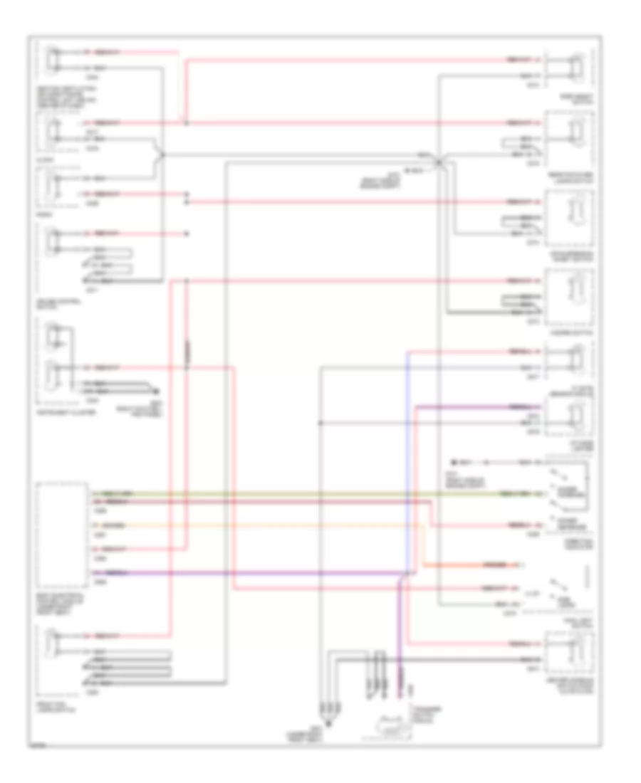
ANTI-LOCK BRAKES
Anti-lock Brake Wiring Diagrams for Land Rover Range Rover SE 1997
 https://portal-diagnostov.com/license.html
Automotive Electricians Portal FZCO
Automotive Electricians Portal FZCO
https://portal-diagnostov.com/license.html
https://portal-diagnostov.com/license.html
Automotive Electricians Portal FZCO
Automotive Electricians Portal FZCO
List of elements for Anti-lock Brake Wiring Diagrams for Land Rover Range Rover SE 1997:
- (1997) (1998)
- (left front of eng compt)
- (left rear of eng compt)
- (left side of eng compt, top of brake fluid reservoir) brake fluid level switch
- (right rear of eng compt)
- Abs booster unit 1-left front 2-right front 4-left rear 5-right rear 6-traction control 7-demanual (left rear of eng compt)
- Abs hydraulic pump (left rear of eng compt)
- Abs power relay
- Abs pressure switch unit (left side of eng compt)
- Abs pump relay
- Anti-lock brake system ecu (behind lower right side of dash)
- Body electrical control module (beneath right front seat)
- C112
- C114
- C172
- C173
- C176
- C177
- C248
- C285
- C507
- Computer data lines system
- Cruise control system
- Data link connector (obd ii) (behind left side of dash, right of steering column)
- Electronic suspension system
- Engine compartment fuse box (right front of eng compt)
- Engine control module (ecm) (right side of eng compt)
- Fuse 10a
- Fuse 30a
- Fuse 5a
- G100
- G104
- G105
- G203 (right footwell trim panel)
- Hot at all times
- Hot in run & start (when ignition relay energized)
- Hot in run & start (when rl10 relay energized)
- Left front wheel speed sensor (behind left front wheel)
- Left rear wheel speed sensor (behind left rear wheel)
- Maxi fuse 3 40a
- Nca
- Ohms
- Pnk
- Pnk/red
- Red
- Resistor (under left side of dash)
- Right front wheel speed sensor (behind right front wheel)
- Right rear wheel speed sensor (behind right rear wheel)
- Solid state
- Stop lamp switch (on brake support)
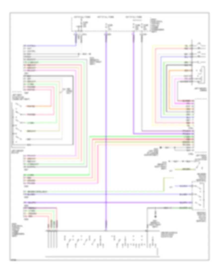
ANTI-THEFT
Anti-theft Wiring Diagram (1 of 2) for Land Rover Range Rover SE 1997
List of elements for Anti-theft Wiring Diagram (1 of 2) for Land Rover Range Rover SE 1997:
- (behind right footwell trim panel)
- (left front side of luggage compt)
- (left side of luggage compt)
- (left side of luggage compt) g400
- (right front side of luggage compt)
- (right side of luggage compt)
- (right side of luggage compt) g401
- Alarm rf aerial module (right side of luggage compt)
- Antenna
- Body electrical control module (beneath right front seat)
- C112
- C257
- C323
- C325
- C326
- C361
- C362
- C507
- C755l
- C755r
- C758l
- C758r
- C762l
- C762r
- C763l
- C763r
- C901a
- C907
- Cdl motor
- Cdl sw
- Door ajar sw
- Engine control module (right side of eng compt)
- Fuse 20a
- Fuse 30a
- G203
- G400
- G401
- Hot at all times
- Ignition switch
- Iii
- Key sw
- Left front door lock actuator (front door trim panel)
- Left front door outstation (behind front door trim panel)
- Left front window motor (behind front door trim panel)
- Left rear window motor (behind front door trim panel)
- Nca
- Red
- Right front door lock actuator (front door trim panel)
- Right front door outstation (behind front door trim panel)
- Right front window motor (behind front door trim panel)
- Right rear window motor (behind front door trim panel)
- Solid state
- Superlock
- Ultrasonic module (top of left "b "pillar)
- W/ memory seat
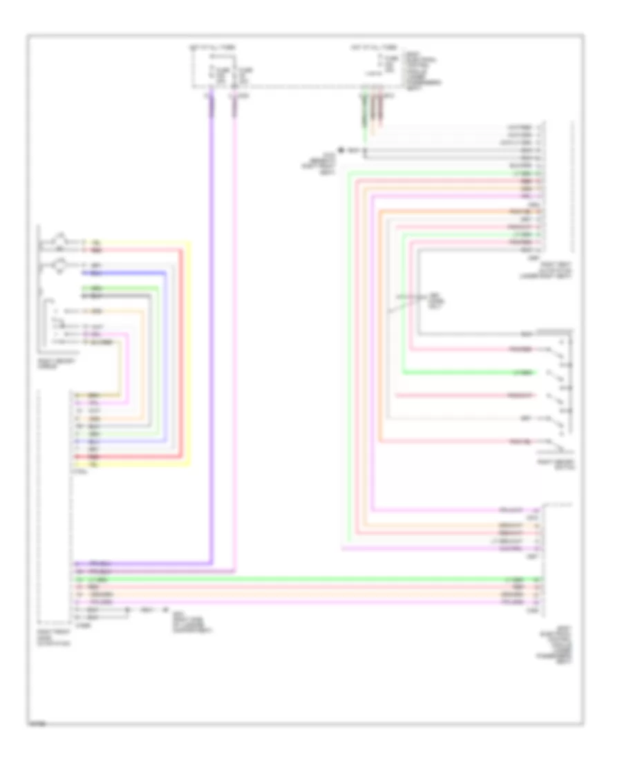
Anti-theft Wiring Diagram (2 of 2) for Land Rover Range Rover SE 1997
List of elements for Anti-theft Wiring Diagram (2 of 2) for Land Rover Range Rover SE 1997:
- (left side of luggage compt)
- (right rear of eng compt)
- (right side of eng compt)
- (right side of luggage compt)
- Alarm sounder (right side of eng compt)
- Battery back up alarm sounder (right side of eng compt)
- Body electrical control module (beneath right front seat)
- C114
- C120
- C133
- C255
- C256
- C258
- C323
- C324
- C325
- C326
- C361
- C362
- C625
- Cdl motor
- Closed on impack
- Door ajar sw
- Engine controls system
- Exterior lights system (side lamps)
- Exterior lights system (turn/ hazard lamps)
- Fuel pump
- Fuel tank module (top of fuel tank)
- G101
- G105
- G105 (right rear of eng compt)
- G203 (right footwell trim panel)
- G400
- G401
- G401 (right side of luggage compt)
- Headlamp system
- Hood switch (near right horn)
- Inertia fuel shut-off switch (behind right footwell trim panel)
- Interior lights system
- Key-in switch (in steering lolumn)
- Left rear door lock actuator (top of left rear door)
- Nca
- Passive immobilization coil (underside of steering column)
- Pnk
- Red
- Right rear door lock actuator (top of right rear door)
- Right tailgate lamps
- Solid state
- Sunroof anti-trap (front center of roof)
- Superlock
- Tailgate switch (center of tailgate)
- Theft alarm led
- W/ battery back up alarm sounder
- W/o battery back up alarm sounder
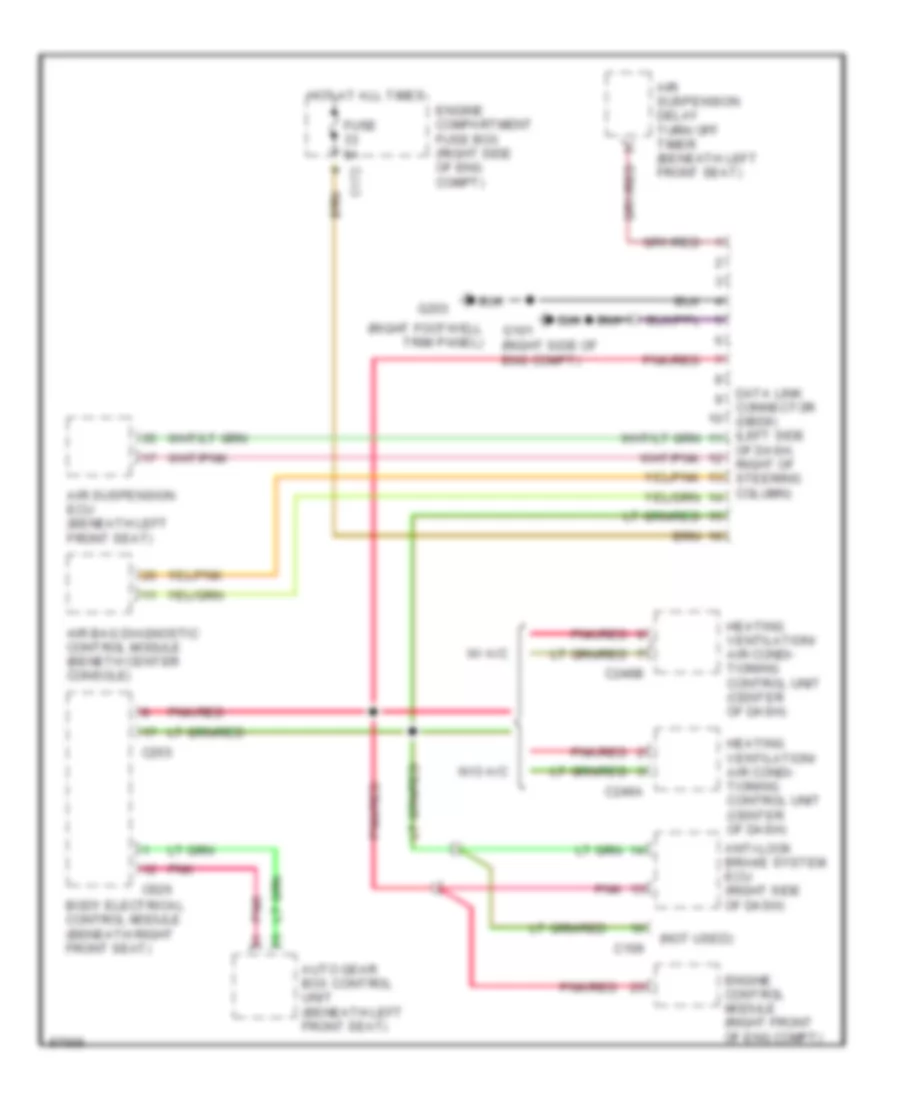
COMPUTER DATA LINES
Computer Data Lines for Land Rover Range Rover SE 1997
List of elements for Computer Data Lines for Land Rover Range Rover SE 1997:
- (not used)
- (right footwell trim panel)
- (right side of eng compt)
- Air bag diagnostic control module (beneth center console)
- Air suspension delay turn off timer (beneath left front seat)
- Air suspension ecu (beneath left front seat)
- Anti-lock brake system ecu (right side of dash)
- Auto gear box control unit (beneath left front seat)
- Body electrical control module (beneath right front seat)
- C106
- C172
- C246a
- C246b
- C255
- C626
- Connector (obdii) (left side
- Data link
- Engine compartment fuse box (right side of eng compt)
- Engine control module (right front of eng compt)
- Fuse 5a
- G101
- G203
- Heating ventilation/ air condi- tioning control unit (center of dash)
- Hot at all times
- Of dash, right of steering column)
- Pnk
- Pnk/red
- W/ a/c
- W/o a/c
COOLING FAN
Cooling Fan Wiring Diagram for Land Rover Range Rover SE 1997
List of elements for Cooling Fan Wiring Diagram for Land Rover Range Rover SE 1997:
- (right rear side of eng compt)
- (right side of eng compt)
- A/c condenser fan 1 relay
- A/c condenser fan 2 relay
- A/c control relay
- A/c dual pressure switch (close- 305 psi open- 247 psi) (left side front bumper)
- C172
- C175
- C176
- C177
- C505
- C508
- C509
- Engine compartment fuse box (right side of eng compt)
- Engine control module (right side of eng compt)
- Engine main control relay
- Fuse 20a
- Fuse 30a
- G101
- G105
- Hot at all times
- Hot in run & start (when ignition relay energized)
- Left condenser fan motor
- Nca
- Right condenser fan motor
- Short- ing link 6
CRUISE CONTROL
Cruise Control Wiring Diagram for Land Rover Range Rover SE 1997
List of elements for Cruise Control Wiring Diagram for Land Rover Range Rover SE 1997:
- (beneath right front seat)
- (pins 11-15 not used)
- (right footwell trim panel)
- A/t only
- Anti-lock brakes system
- Body electrical control unit (beneath right front seat)
- Brake switch vent valve (on brake pedal support)
- C112
- C255
- C285
- C505
- Clock spring (top of steering column)
- Clutch pedal position switch (left side of dash)
- Cruise control converter/ inverter module (right of steering column)
- Cruise control module (right of steering column)
- Cruise control switch
- Cruise control switches
- Cruise control vacuum pump (left rear corner of eng compt) of eng compt)
- Engine control module (behind battery)
- Fuse 10a
- G203
- G301
- Gear box position switch (left side of transmission)
- Hot in run & start
- Interior lights system
- M/t only
- Nca
- Red
- Res/ decel
- Set/ accel
- Solid state
- Stop lamp switch (on brake pedal support)
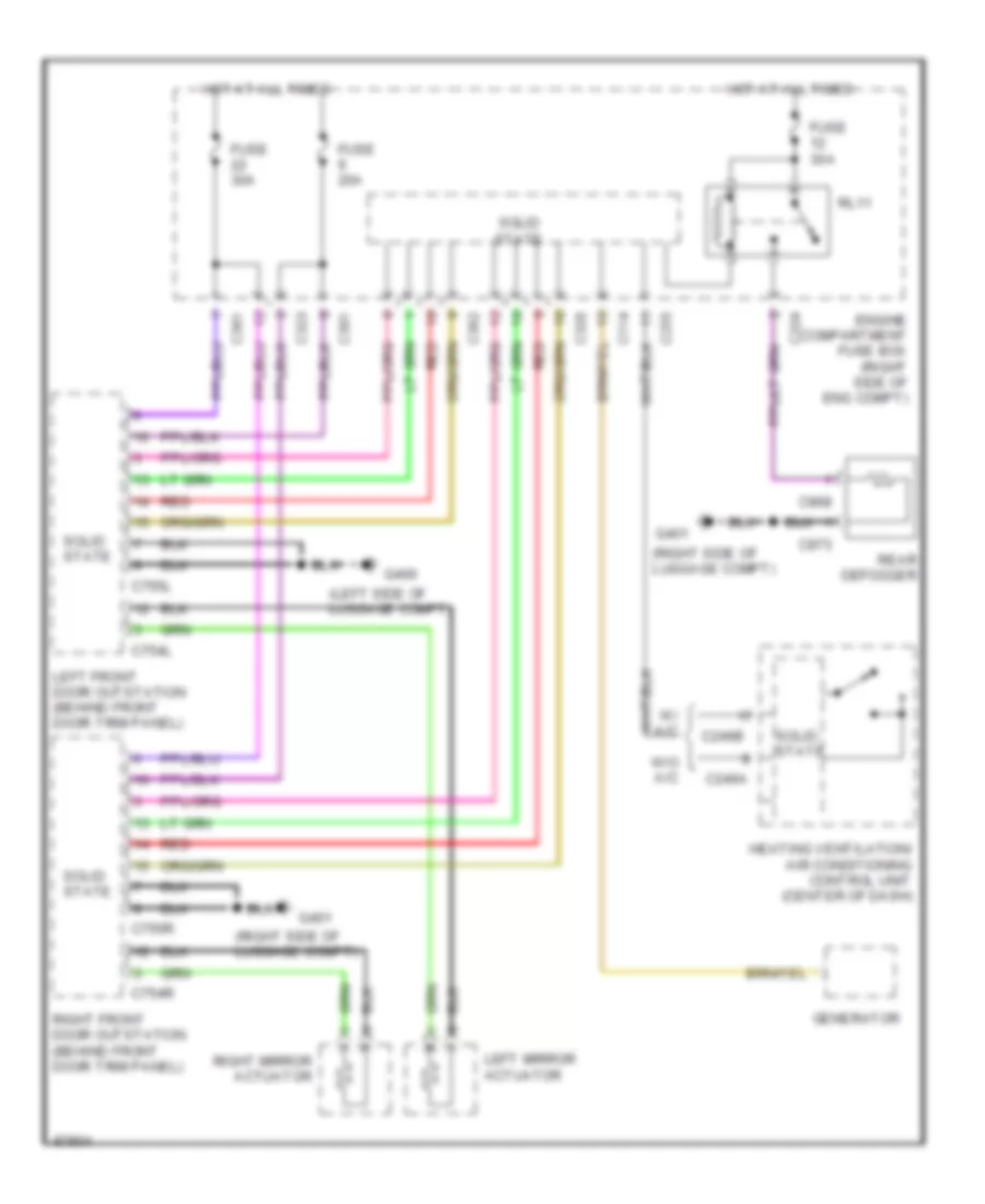
DEFOGGERS
Heated Windshield Wiring Diagram for Land Rover Range Rover SE 1997
List of elements for Heated Windshield Wiring Diagram for Land Rover Range Rover SE 1997:
- (center rear of eng compt)
- (right rear of eng compt)
- Body electrical control module (beneath right front seat)
- C114
- C128
- C130
- C172
- C173
- C244
- C246a
- C246b
- C255
- C507
- Engine compartment fuse box (right side of eng compt)
- Engine control module (right side of eng compt)
- Fuse 30a
- G121
- G167
- Generator
- Heated windshield
- Heating ventilation/ air conditioning control unit (center of dash)
- Hot at all times
- Hot in run & start (when ignition relay energized)
- Left heated windshield relay
- Nca
- Right heated windshield relay
- Solid state
- W/ a/c
- W/o a/c
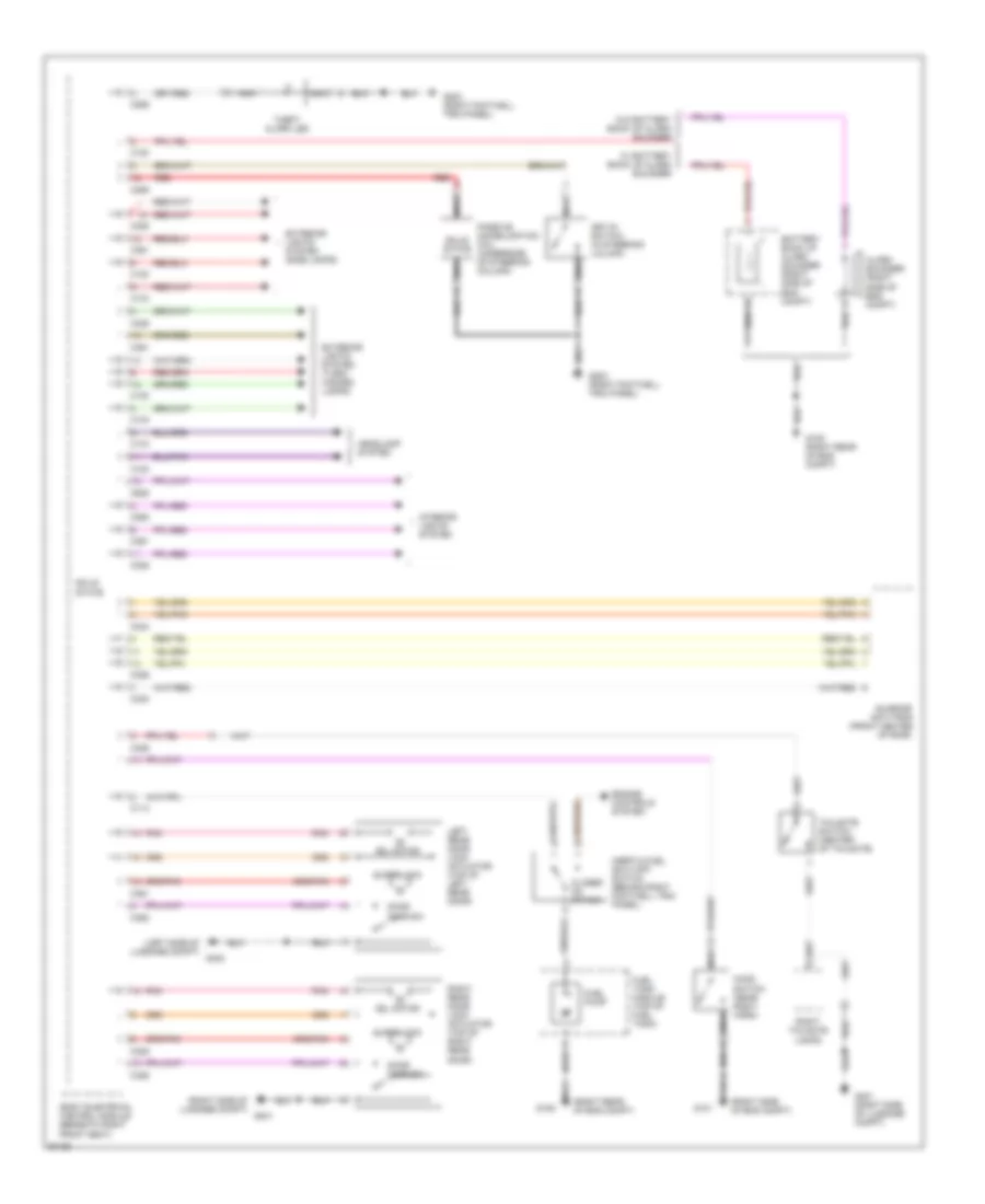
Rear Defogger & Heated Mirrors Wiring Diagram for Land Rover Range Rover SE 1997
List of elements for Rear Defogger & Heated Mirrors Wiring Diagram for Land Rover Range Rover SE 1997:
- (left side of luggage compt)
- (right side of luggage compt)
- C114
- C246a
- C246b
- C255
- C323
- C324
- C326
- C361
- C362
- C754l
- C754r
- C755l
- C755r
- C868
- C873
- Engine compartment fuse box (right side of eng compt)
- Fuse 20a
- Fuse 30a
- G400
- G401
- Generator
- Heating ventilation/ air conditioning control unit (center of dash)
- Hot at all times
- Left front door outstation (behind front door trim panel)
- Left mirror actuator
- Rear defogger
- Red
- Right front door outstation (behind front door trim panel)
- Right mirror actuator
- Rl11
- Solid state
- W/ a/c
- W/o a/c
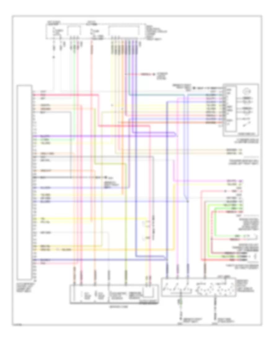
ELECTRONIC SUSPENSION
Electronic Suspension Wiring Diagram for Land Rover Range Rover SE 1997
List of elements for Electronic Suspension Wiring Diagram for Land Rover Range Rover SE 1997:
- (below left front seat) air suspension delay timer
- (left rear of engine compt) air suspension compressor
- (left side of dash, right of steering column)
- (right rear of engine compt) g105
- Air susp ind
- Air suspension compressor relay
- Air suspension ecu (beneath left front seat)
- Air suspension inhibit switch (center of dash)
- Air valve block (left side of engine compt)
- Anti-lock brakes system
- Body electrical control module (below right front seat)
- C112
- C114
- C172
- C174
- C176
- C258
- C326
- C362
- Ctrl unit
- Data link connector (obdii)
- Door locks system
- Dwn
- Engine compartment fuse box (right side of eng compt)
- Engine controls system
- Fuse 10a
- Fuse 5a
- G100 (left front of engine compt)
- G101 (right side of engine compt)
- G104 (left rear of engine compt)
- Hot at all times
- Hot in run or acc
- Instrument cluster
- Interior lights system
- Left front height sensor (beneath left side of vehicle, on chassis)
- Left rear height sensor (beneath left side of vehicle, on chassis)
- Maxi fuse 30a
- Red
- Ride height switch (center of dash)
- Right front height sensor (beneath right side of vehicle, on chassis)
- Right rear height sensor (beneath right side of vehicle, on chassis)
- Solid state
- Stop lamp switch (on brake pedal support)
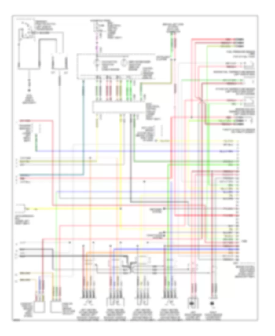
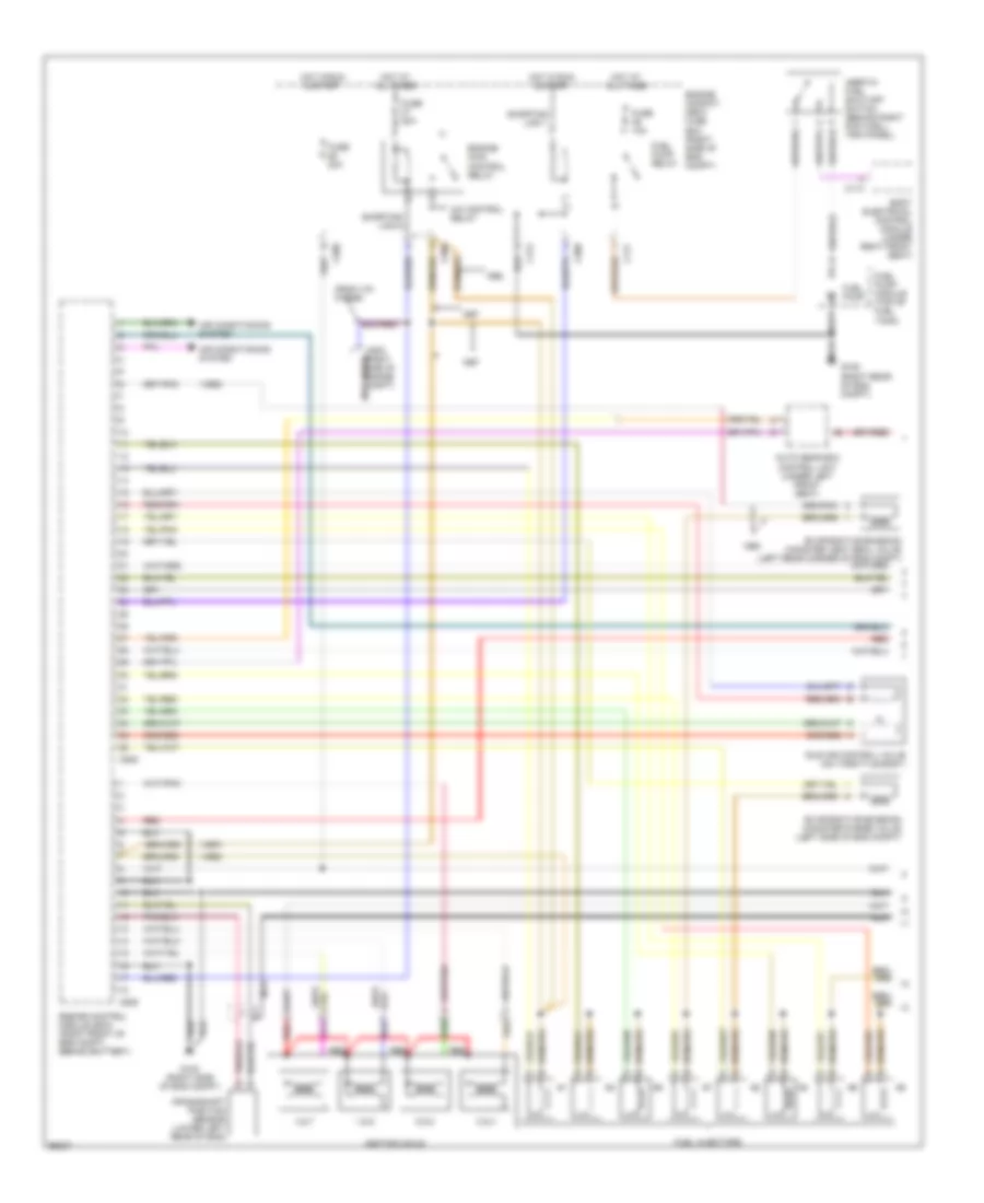
ENGINE PERFORMANCE
4.0L
4.0L, Engine Performance Wiring Diagrams (1 of 2) for Land Rover Range Rover SE 1997
List of elements for 4.0L, Engine Performance Wiring Diagrams (1 of 2) for Land Rover Range Rover SE 1997:
- (1997)
- (1998)
- (from vin 370859)
- (not used)
- 1 & 6
- 2 & 3
- 4 & 7
- 5 & 8
- A/c control relay
- Air conditioning system
- Auto gear box control unit (under left front seat)
- Body electrical control module (under right front seat)
- C114
- C117
- C172
- C502 (right side of engine compt)
- C505
- C508
- C509
- Crankshaft position sensor (lower left rear of eng)
- Engine compat- ment fuse box (right side of eng compt)
- Engine control module (ecm) (right front of eng compt, behind battery)
- Engine main control relay
- Evaporative emission canister purge valve (left side of eng compt)
- Evaporative emission canister vent seal valve (left rear corner of eng compt)
- Fuel injectors
- Fuel pump
- Fuel pump module (top of fuel tank)
- Fuel pump relay
- Fuse 10a
- Fuse 20a
- G103 (right side of eng compt)
- G105 (right rear of eng compt)
- Hot at all times
- Hot in run & start
- Idle air control valve (on throttle body)
- Ignition coils
- Inertia fuel shut-off switch (behind right footwell trim panel)
- Nca
- Red
- Shorting link 1
- Shorting link 6
4.0L, Engine Performance Wiring Diagrams (2 of 2) for Land Rover Range Rover SE 1997
List of elements for 4.0L, Engine Performance Wiring Diagrams (2 of 2) for Land Rover Range Rover SE 1997:
- (1998)
- (behind left side of dash) data link connector
- A/t
- Air conditioning system
- Air suspension ecu (under left front seat)
- Anti-lock brake system (ecu) (behind lower right side of dash)
- Body electrical control module (under right front seat)
- C112
- C114
- C242
- C255
- C256
- C258
- C507
- Camshaft position sensor (left front of eng)
- Control unit & message center display
- Defogger system
- Engine control module (ecm) (right front of eng compt, behind battery)
- Engine coolant temperature sensor (left side of eng)
- Engine fuel temperature sensor (left side of eng)
- Fuel pressure sensor (1998) (top of fuel tank)
- Fuse 10a
- G103 (right side of eng compt)
- Gear box position switch (left side of transmission)
- Hot at all times
- Instrument cluster
- Intake air temperature sensor (left side of eng compt, on air cleaner)
- Left heated oxygen sensor (behind left exhaust manifold, on exhaust pipe)
- Left heated oxygen sensor (post catalyst) (downstream of catalytic convert)
- Left knock sensor (lower left side of eng)
- M/t
- Malfunction indicator lamp (check engine)
- Mass air flow sensor (on intake air duct)
- Nca
- Pnk/red
- Red
- Right heated oxygen sensor (behind right exhaust manifold, on exhaust pipe)
- Right heated oxygen sensor (post catalyst) (downstream of catalytic convert)
- Right knock sensor (lower right side of eng)
- Service reminder indicator (service engine)
- Throttle position sensor (on throttle body)
- Transfer gear box ecu (under left front seat)
4.6L
4.6L, Engine Performance Wiring Diagrams (1 of 2) for Land Rover Range Rover SE 1997
List of elements for 4.6L, Engine Performance Wiring Diagrams (1 of 2) for Land Rover Range Rover SE 1997:
- (1997)
- (1998)
- (from vin 370859)
- (not used)
- 1 & 6
- 2 & 3
- 4 & 7
- 5 & 8
- A/c control relay
- Air conditioning system
- Auto gear box control unit (under left front seat)
- Body electrical control module (under right front seat)
- C114
- C117
- C172
- C502 (right side of engine compt)
- C505
- C508
- C509
- Crankshaft position sensor (lower left rear of eng)
- Engine compat- ment fuse box (right side of eng compt)
- Engine control module (ecm) (right front of eng compt, behind battery)
- Engine main control relay
- Evaporative emission canister purge valve (left side of eng compt)
- Evaporative emission canister vent seal valve (left rear corner of eng compt)
- Fuel injectors
- Fuel pump
- Fuel pump module (top of fuel tank)
- Fuel pump relay
- Fuse 10a
- Fuse 20a
- G103 (right side of eng compt)
- G105 (right rear of eng compt)
- Hot at all times
- Hot in run & start
- Idle air control valve (on throttle body)
- Ignition coils
- Inertia fuel shut-off switch (behind right footwell trim panel)
- Nca
- Red
- Shorting link 1
- Shorting link 6
4.6L, Engine Performance Wiring Diagrams (2 of 2) for Land Rover Range Rover SE 1997
List of elements for 4.6L, Engine Performance Wiring Diagrams (2 of 2) for Land Rover Range Rover SE 1997:
- (1998)
- (behind left side of dash) data link connector
- A/t
- Air conditioning system
- Air suspension ecu (under left front seat)
- Anti-lock brake system (ecu) (behind lower right side of dash)
- Body electrical control module (under right front seat)
- C112
- C114
- C242
- C255
- C256
- C258
- C507
- Camshaft position sensor (left front of eng)
- Control unit & message center display
- Defogger system
- Engine control module (ecm) (right front of eng compt, behind battery)
- Engine coolant temperature sensor (left side of eng)
- Engine fuel temperature sensor (left side of eng)
- Fuel pressure sensor (1998) (top of fuel tank)
- Fuse 10a
- G103 (right side of eng compt)
- Gear box position switch (left side of transmission)
- Hot at all times
- Instrument cluster
- Intake air temperature sensor (left side of eng compt, on air cleaner)
- Left heated oxygen sensor (behind left exhaust manifold, on exhaust pipe)
- Left heated oxygen sensor (post catalyst) (downstream of catalytic convert)
- Left knock sensor (lower left side of eng)
- M/t
- Malfunction indicator lamp (check engine)
- Mass air flow sensor (on intake air duct)
- Nca
- Pnk/red
- Red
- Right heated oxygen sensor (behind right exhaust manifold, on exhaust pipe)
- Right heated oxygen sensor (post catalyst) (downstream of catalytic convert)
- Right knock sensor (lower right side of eng)
- Service reminder indicator (service engine)
- Throttle position sensor (on throttle body)
- Transfer gear box ecu (under left front seat)
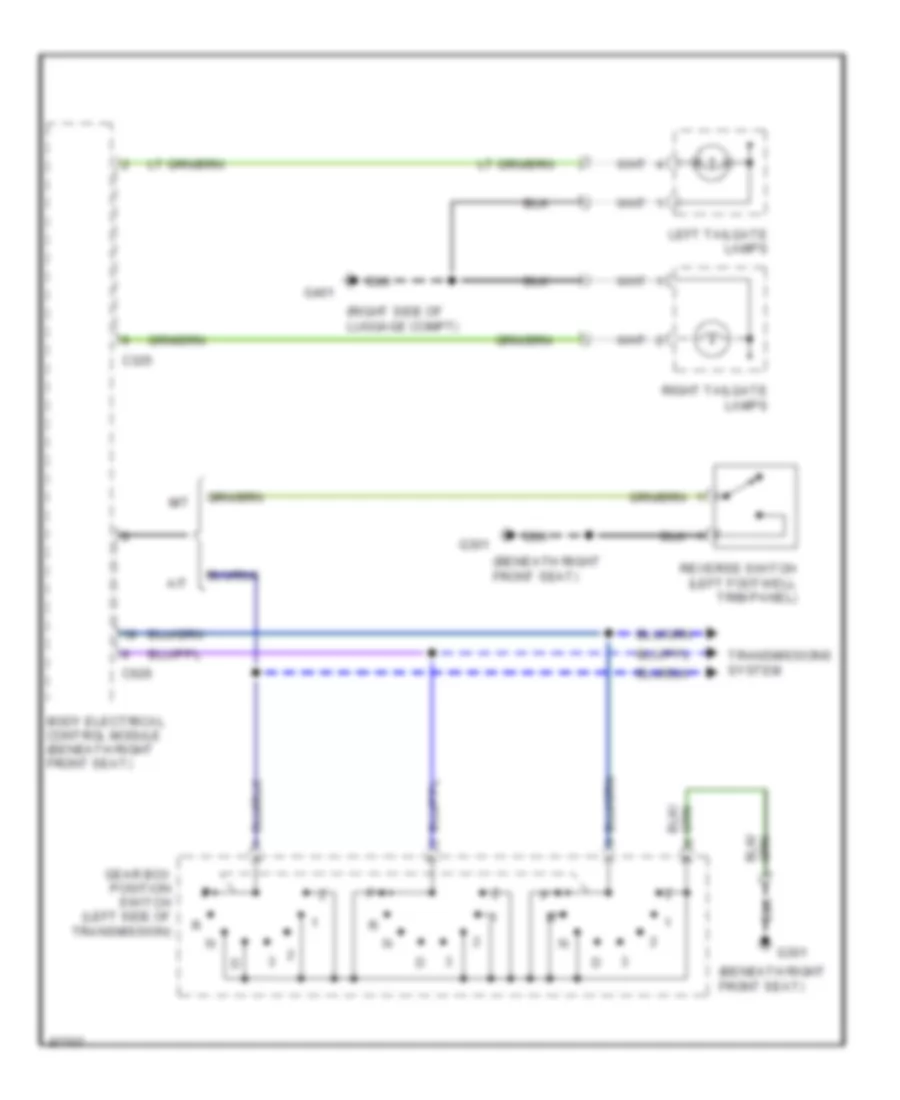
EXTERIOR LIGHTS
Back-up Lamps Wiring Diagram for Land Rover Range Rover SE 1997
List of elements for Back-up Lamps Wiring Diagram for Land Rover Range Rover SE 1997:
- (beneath right front seat)
- (right side of luggage compt)
- A/t
- Body electrical control module (beneath right front seat)
- C325
- C626
- G301
- G401
- Gear box position switch (left side of transmission)
- Left tailgate lamps
- M/t
- Reverse switch (left footwell trim panel)
- Right tailgate lamps
- Transmissions system
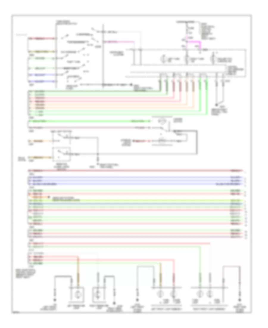
Exterior Lamps Wiring Diagram (1 of 2) for Land Rover Range Rover SE 1997
List of elements for Exterior Lamps Wiring Diagram (1 of 2) for Land Rover Range Rover SE 1997:
- (behind right foowell trim panel)
- (left front of eng compt)
- (right footwell trim panel)
- (right rear of eng compt)
- Body electrical control module (beneath right front seat)
- C113
- C120
- C242
- C255
- C256
- C257
- C323
- C325
- C361
- Control unit/message center display
- Dim decrease
- Dim increase
- Fuse 10a
- G100 (left front of eng compt)
- G101 (right side of eng compt)
- G105
- G203
- G252 (right footwell trim panel)
- Hazard switch
- Headlamp flash
- Headlight system (rear fog guard lamps)
- Hot at all times
- Instrument cluster
- Interior lights system
- Left front lamp assembly
- Left repeater lamp
- Left turn
- Left turn ind
- Main beam
- Main light switch
- Mode
- Overspeed
- Rear fog guard lamps switch
- Right front lamp assembly
- Right repeater lamp
- Right turn
- Right turn ind
- Side lamp
- Solid state
- Trailer tow warning ind
- Turn lamp
- Turn signal indicator switch
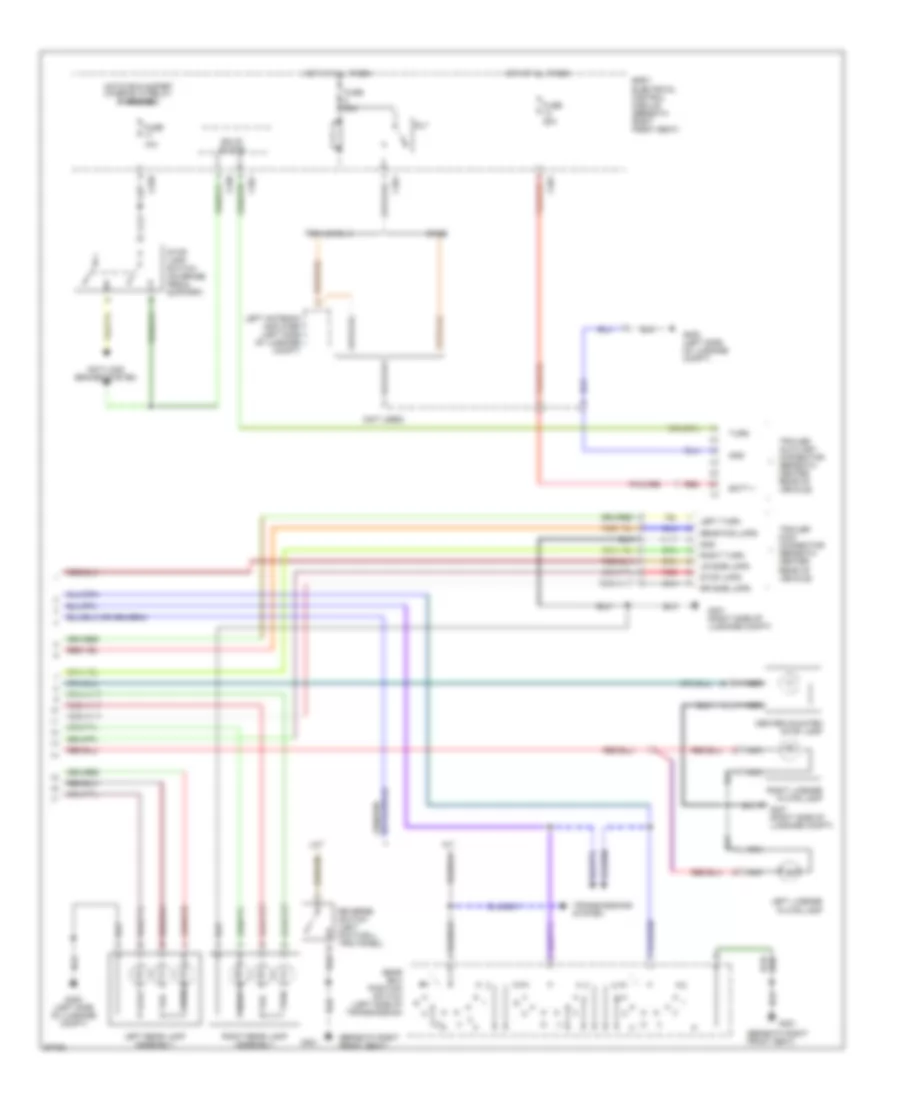
Exterior Lamps Wiring Diagram (2 of 2) for Land Rover Range Rover SE 1997
List of elements for Exterior Lamps Wiring Diagram (2 of 2) for Land Rover Range Rover SE 1997:
- (beneath right front seat)
- (not used)
- A/t
- Anti-lock brakes system
- Base
- Batt +
- Body electrical control module (beneath right front seat)
- C258
- C361
- Center mounted stop lamp
- Fuse 10a
- Fuse 20a
- Fuse 30a
- G301
- G400 (left side of luggage compt)
- G401 (right side of luggage compt)
- Gear box position switch (left side of transmission)
- Gnd
- Hot at all times
- Hot in run & start (when rl10 relay energized)
- Left antenna amplifier (left side of luggage compt)
- Left license plate lamp
- Left rear lamp assembly
- Left turn
- Lr side lmps
- M/t
- Nca
- Rear fog lmps
- Red
- Reverse switch (left footwell trim panel)
- Right license plate lamp
- Right rear lamp assembly
- Right turn
- Rl7
- Rr side lmps
- Solid state
- Stop
- Stop lamp switch (on brake pedal support)
- Stop lmps
- Tail
- Trailer auxiliary connector (beneath center rear of vehicle)
- Trailer main connector (beneath center rear of vehicle)
- Transmissions system
- Trim level 3
- Turn
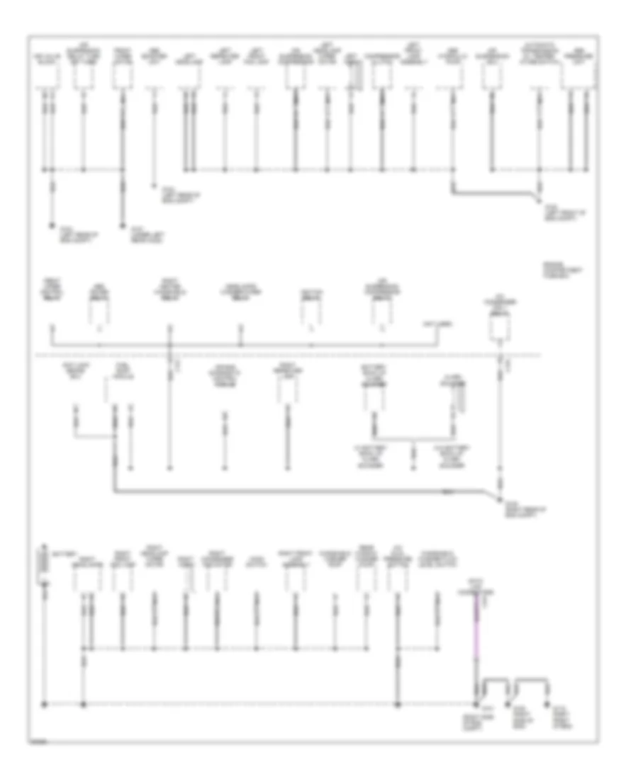
GROUND DISTRIBUTION
Ground Distribution Wiring Diagram (1 of 4) for Land Rover Range Rover SE 1997
List of elements for Ground Distribution Wiring Diagram (1 of 4) for Land Rover Range Rover SE 1997:
- (not used)
- (right side of eng compt)
- A/c condenser fan 1 relay
- A/c dual pressure switch
- Abs booster unit
- Abs hydraulic pump
- Abs power relay
- Abs pressure unit
- Air bag diagnostic control module
- Air suspension compressor
- Air suspension compressor relay
- Air suspension delay turn off timer
- Air suspension ecu
- Air valve block
- Alarm sounder
- Anti-lock brake ecu
- Automatic transmission oil temper- ature switch
- Battery
- Battery back up alarm sounder
- C172
- C176
- C231
- Compressor clutch
- Engine compartment fuse box
- Front wiper control relay
- Front wiper motor
- Fuel pump module
- G100 (left front of eng compt)
- G101
- G104 (left rear of eng compt)
- G105 (right rear of eng compt)
- G119 (right front of eng)
- G120 (right side of eng)
- G127 (under left rear hood)
- Headlamps washer/wiper relay
- Hood switch
- Ignition relay
- Left front fog lamp
- Left front lamp assembly
- Left headlamp
- Left headlamp wiper motor
- Left horn
- Left repeater lamp
- Nca
- Rear window washer pump
- Right condenser fan motor
- Right front fog lamp
- Right front lamp assembly
- Right headlamp wiper motor
- Right headlamps
- Right heated windshield relay
- Right horn
- Right repeater lamp
- W/ battery back up alarm sounder
- W/o battery back up alarm sounder
- Windshield washer fluid level switch
- Windshield washer pump
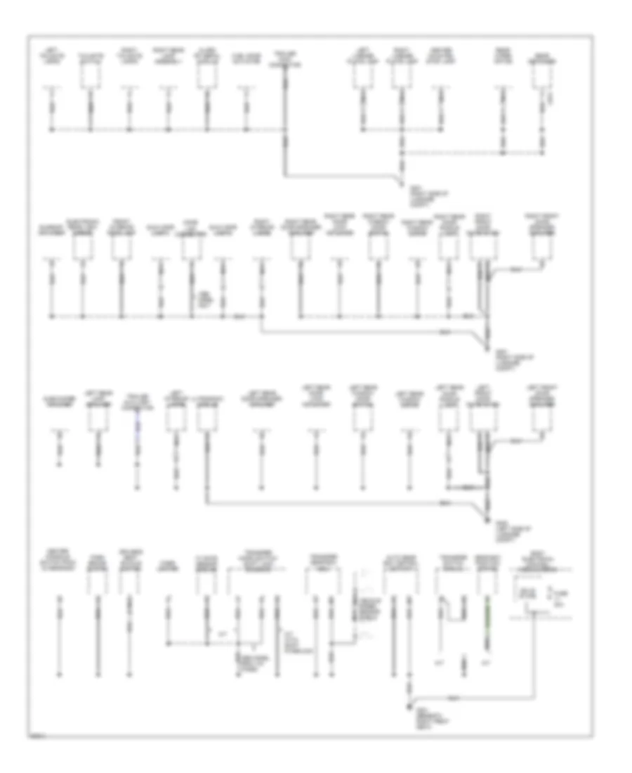
Ground Distribution Wiring Diagram (2 of 4) for Land Rover Range Rover SE 1997
List of elements for Ground Distribution Wiring Diagram (2 of 4) for Land Rover Range Rover SE 1997:
- Air suspension inhibit switch
- C242
- C244
- Clock
- Clock spring
- Clutch pedal position switch
- Cruise control ecu
- Cruise control switch
- Data link connector (obdii)
- From vin
- Front fog lamp switch
- Fuel door release switch
- G121 (center rear of eng compt)
- G203 (right footwell trim panel)
- G302 (front of center console, behind heater & a/c control panel)
- Glove box lamp
- Hazard switch
- Heated windshield
- Heating ventilation/ air conditioning control unit
- Ignition key lock solenoid
- Ignition switch
- Instrument cluster
- Key-in switch
- Left blower motor
- Main light switch
- Nca
- Passive immobilization coil
- Radio
- Rear fog guard lamps switch
- Resistor
- Ride height switch
- Right blower motor
- Steering wheel switches
- Theft alarm led
- Turn signal switch
- Up to vin
- W/ shift inter-lock up to vin
- Washer/ wiper switch
Ground Distribution Wiring Diagram (3 of 4) for Land Rover Range Rover SE 1997
List of elements for Ground Distribution Wiring Diagram (3 of 4) for Land Rover Range Rover SE 1997:
- "h" gate sensor module
- A/t
- A/t with shift interlock
- Alarm rf aerial module
- Auto gear box control unit (a/t)
- Body electrical control module (becm)
- C873
- Center console switch pack outstation
- Center mounted stop lamp
- Cigar lighter
- Driver's seat buckle switch
- Electronic rear view mirror
- Front interior roof lamp
- Fuel door actuator
- Fuse 30a
- G301 (beneath right front seat)
- G400 (left side of luggage compt)
- G401 (right side of luggage compt)
- Gear box position switch
- Home link connector
- Left front door outstation
- Left front door speaker amplifier
- Left interior lamps
- Left license plate lamp
- Left rear door lock actuator
- Left rear door puddle lamp
- Left rear door speaker amplifier
- Left rear lamp amplifier
- Left rear window door switch
- Left rear window motor
- Left tailgate lamps
- M/t
- Model only
- Nca
- Park brake switch
- Rear defogger
- Rear wiper mptor
- Right front door outstation
- Right front door speaker amplifier
- Right interior lamps
- Right license plate lamp
- Right rear door lock actuator
- Right rear door puddle lamp
- Right rear door speaker amplifier
- Right rear lamp assembly
- Right rear window door switch
- Right rear window motor
- Right tailgate lamps
- Solid state
- Subwoofer amplifier
- Sun-visor lamp 1
- Sun-visor lamp 2
- Sunroof anti-trap
- Tailgate switch
- Trailer auxiliary connector
- Trailer main connector
- Transfer gear box ecu
- Transfer micro switch/ shift lock solenoid
- Transfer switch manual
- Ultrasonic module
- Vehicle speed sensor shield
Ground Distribution Wiring Diagram (4 of 4) for Land Rover Range Rover SE 1997
List of elements for Ground Distribution Wiring Diagram (4 of 4) for Land Rover Range Rover SE 1997:
- A/t
- C507
- C509
- C566
- Crankshaft position sensor shield
- Engine control module (ecm)
- Engine coolant temperature gauge sensor
- G103 (right side of eng compt)
- G301 (beneath right front seat)
- Gear box position switch
- Left heated seat
- Left heated oxygen sensor shield
- Left knock sensor shield
- Left oxygen sensor shield (post catalyst)
- Left seat outstation
- Left seat switch
- M/t
- Nca
- Neutral switch
- Reverse switch
- Right heated oxygen sensor shield
- Right heated seat
- Right knock sensor shield
- Right oxygen sensor shield (post catalyst)
- Right seat outstation
- Right seat switch
- Transfer box oil transfer switch
- W/ power seat
- W/o power seat
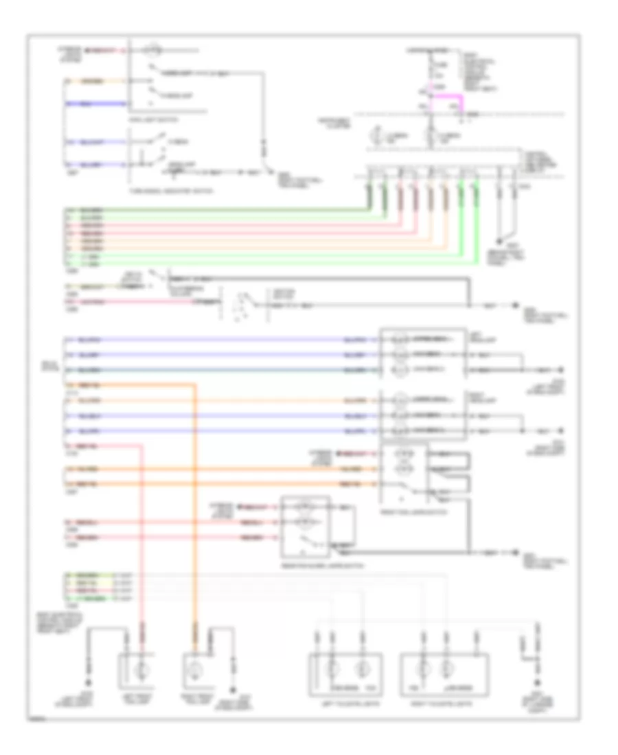
HEADLIGHTS
Headlight Wiring Diagram for Land Rover Range Rover SE 1997
List of elements for Headlight Wiring Diagram for Land Rover Range Rover SE 1997:
- (behind right foowell trim panel)
- (in steering column)
- (right side of eng compt)
- Body electrical control module (beneath right front seat)
- C113
- C120
- C242
- C255
- C256
- C257
- C325
- Control unit/mess- age center display
- Dipped beam
- Fog
- Front fog lamps switch
- Fuse 10a
- G100 (left front of eng compt)
- G101
- G101 (right side of eng compt)
- G203
- G203 (right footwell trim panel)
- G252 (right footwell trim panel)
- G401 (right side of luggage compt)
- Headlamp
- Headlamp flash
- Hi beam
- Hi beam ind
- Hot at all times
- Ignition switch
- Iii
- Instrument cluster
- Interior lights system
- Key-in switch
- Left front fog lamp
- Left headlamp
- Left tailgate lights
- Lo beam ind
- Main beam
- Main beam 2
- Main light switch
- Nca
- Rear fog guard lamps switch
- Reverse
- Right front fog lamp
- Right headlamp
- Right tailgate lights
- Side lamp
- Solid state
- Turn signal indicator switch
HORN
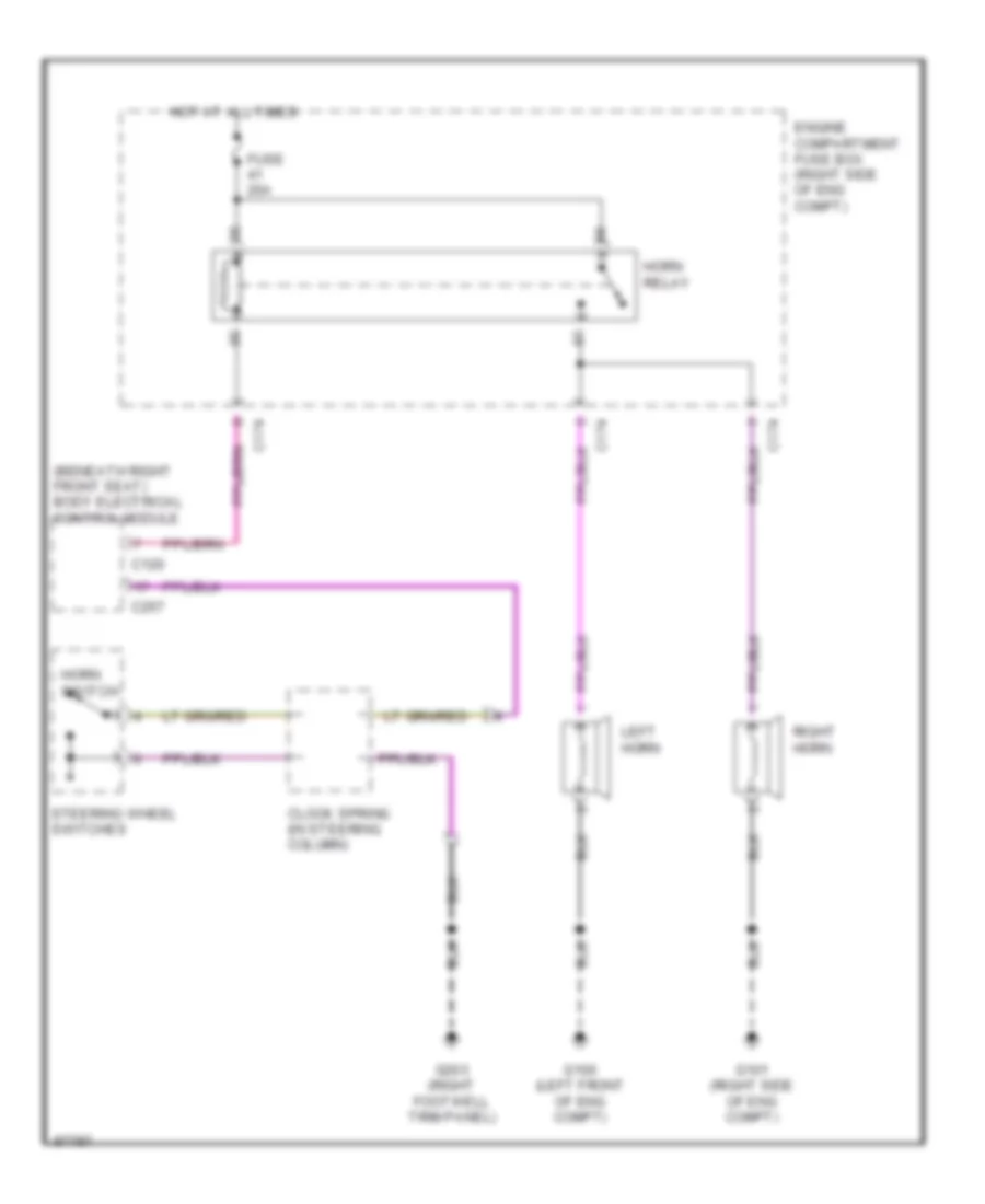
Horn Wiring Diagram for Land Rover Range Rover SE 1997
List of elements for Horn Wiring Diagram for Land Rover Range Rover SE 1997:
- (beneath right front seat) body electrical control module
- C120
- C174
- C257
- Clock spring (in steering column)
- Engine compartment fuse box (right side of eng compt)
- Fuse 20a
- G100 (left front of eng compt)
- G101 (right side of eng compt)
- G203 (right footwell trim panel)
- Horn relay
- Horn switch
- Hot at all times
- Left horn
- Right horn
- Steering wheel switches
INSTRUMENT CLUSTER
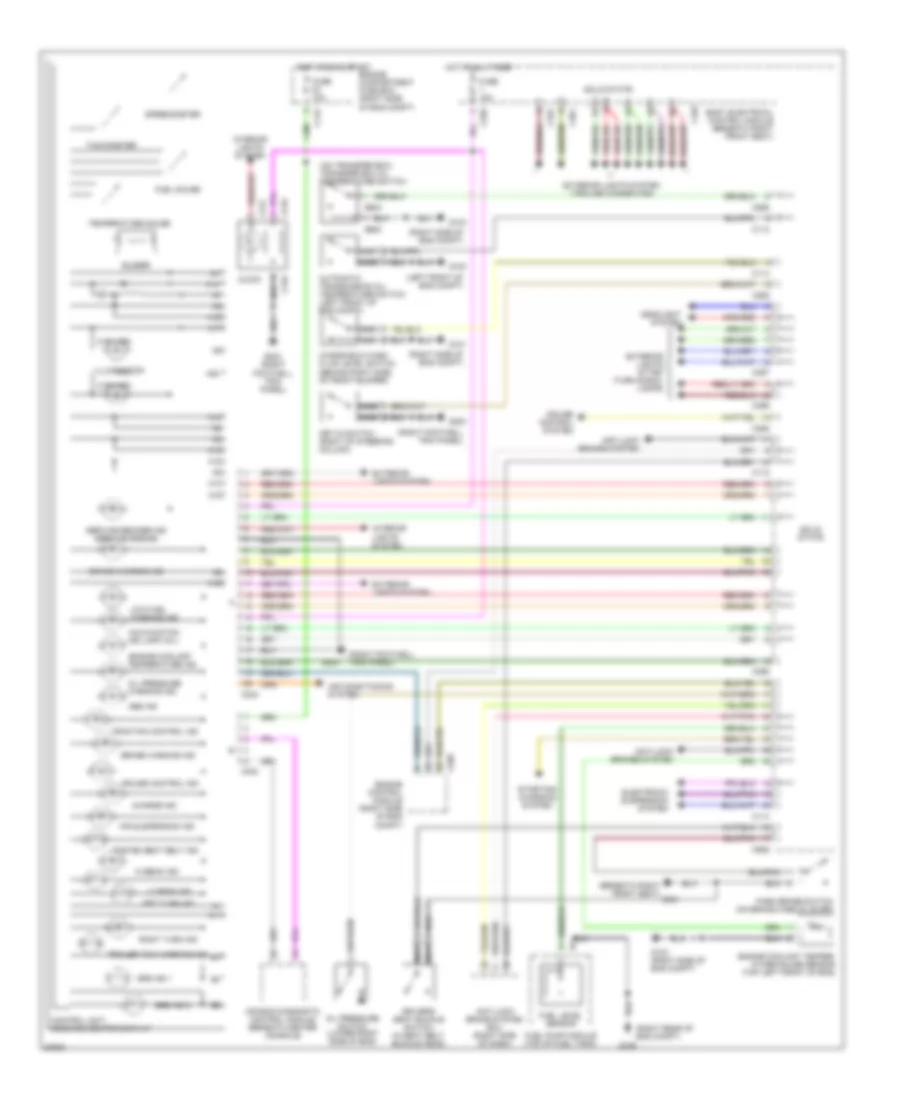
Instrument Cluster Wiring Diagram for Land Rover Range Rover SE 1997
List of elements for Instrument Cluster Wiring Diagram for Land Rover Range Rover SE 1997:
- (3 bulbs)
- (beneath right front seat) g301
- (left front of eng compt)
- (on transfer box) transfer box oil temperature switch
- (right footwell trim panel)
- (right rear of eng compt)
- (right side of eng compt)
- A10
- A11
- A12
- A13
- A14
- A15
- A16
- A17
- A18
- A19
- A20
- Abs ind
- Air bag diagnostic control module (beneath center console)
- Air conditioning system
- Air suspension ind
- Anti-lock brake system ecu (right side of dash)
- Anti-lock brakes system
- Automatic transmission oil temperature switch (left front of eng compt)
- Body electrical control module (beneath right front seat)
- Brake warning ind
- Buzzer
- C112
- C114
- C175
- C216
- C217
- C242
- C255
- C256
- C257
- C258
- C323
- C325
- C361
- C402
- C505
- C565
- C566
- C626
- Charge ind
- Clock
- Control unit/ message center display
- Cruise control ind
- Cruise control system
- Driver's seat buckle switch (in seat belt buckle head)
- Electronic suspension system
- Engine compartment fuse box (right side of eng compt)
- Engine control module (right side of eng compt)
- Engine coolant temper- ature gauge sensor (top left front of eng)
- Engine coolant temperature ind
- Exterior lights system
- Exterior lights system (trailer connector)
- Exterior lights sytem (turn signal lamps)
- Fasten seat belt ind
- Fuel gauge
- Fuel level sensor
- Fuel pump module (top of fuel tank)
- Fuse 10a
- G100
- G101
- G103
- G103 (right side of eng compt)
- G105
- G203
- G203 (right footwell trim panel)
- Headlight system
- Hi beam ind
- Hot at all times
- Hot in run & start
- Illumination
- Interior lights system
- Key-in switch (right of steering column)
- Left turn ind
- Lo beam ind
- Low fuel warning ind
- Malfucntion ind lamp (mil)
- Nac
- Nca
- Oil pressure switch (lower right side of eng)
- Oil pressure warning ind
- Park brake switch (on brake handle lever)
- Right turn ind
- Service remider ind (service engine)
- Solid state
- Speedometer
- Srs ind 1
- Srs ind 2
- Starting/ charging system
- Tachometer
- Temperature gauge
- Traction control ind
- Trailer tow warning ind
- Windshield wash fluid level switch (behind right side of front bumper)
INTERIOR LIGHTS
Courtesy Lamps Wiring Diagram (1 of 2) for Land Rover Range Rover SE 1997
List of elements for Courtesy Lamps Wiring Diagram (1 of 2) for Land Rover Range Rover SE 1997:
- Body electrical control module (under right front seat)
- C229
- C249
- C258
- C311
- C315
- C323
- C324
- C325
- C326
- C329
- C361
- C362
- C363
- C613
- C625
- C714l
- C714r
- C814
- C816
- Footwell lamp 1
- Footwell lamp 2
- Front interior roof lamp
- Fuse f1 10a
- Fuse f13 20a
- Fuse f15 20a
- Fuse f6 10a
- G400 (left side of luggage compt)
- G401 (right side of luggage compt)
- Hot at all times
- Hot w/ rl10 relay energized
- Left interior light
- Left rear door lock actuator
- Model
- Nca
- Rear footwell lamp
- Red
- Right rear door lock actuator
- Right tailgate lights
- Sun visor lamp 1
- Sun visor lamp 2
- Tailgate switch
Courtesy Lamps Wiring Diagram (2 of 2) for Land Rover Range Rover SE 1997
List of elements for Courtesy Lamps Wiring Diagram (2 of 2) for Land Rover Range Rover SE 1997:
- C205
- C319
- C708l
- C708r
- C755l
- C755r
- C757l
- C757r
- C758l
- C758r
- C762l
- C762r
- C763l
- C763r
- C863
- C864
- G101 (right side of engine compartment)
- G400 (left side of luggage compt)
- G401 (right side of luggage compt)
- Glove box lamp
- Left front door lock actuator
- Left front door out- station
- Left front puddle lamp
- Left rear puddle lamp
- Nca
- Rear load space lamp
- Red
- Right front door lock actuator
- Right front door out- station
- Right front puddle lamp
- Right interior light
- Right rear puddle lamp
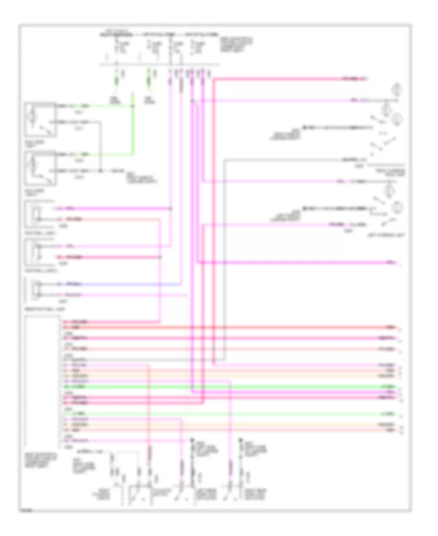
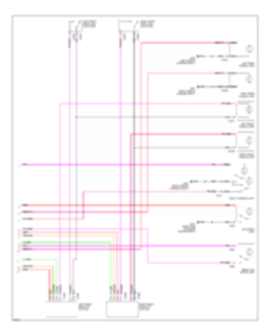
Instrument Illumination Wiring Diagram for Land Rover Range Rover SE 1997
List of elements for Instrument Illumination Wiring Diagram for Land Rover Range Rover SE 1997:
- "h" gate sensor module
- Air suspension inhibit switch
- Body electrical control module (under right front seat)
- C211
- C212
- C213
- C214
- C215
- C216
- C217
- C219
- C220
- C226
- C236
- C242
- C244
- C256
- C257
- C258
- C614
- C617
- C618
- C619
- C625
- C635
- Center console switch pack outstation
- Clock
- Cruise control switch
- Dimmer decrease
- Dimmer increase
- Direction indicator
- Front fog lamps switch
- G101 (right side of engine compt)
- G203 (right footwell trim panel)
- G301 (under right front seat)
- Hazard switch
- Heating ventilation/ air conditioning control unit (hevac) (center of dash)
- I/p cigar lighter
- Illum
- Instrument cluster
- Main light switch
- Radio
- Rear fog guard lamps switch
- Ride height switch
- Side lamps
- Transfer switch manual
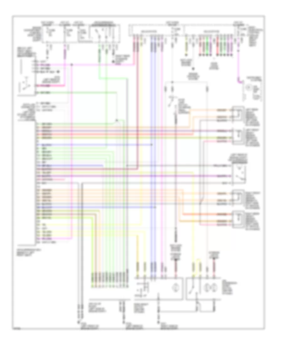
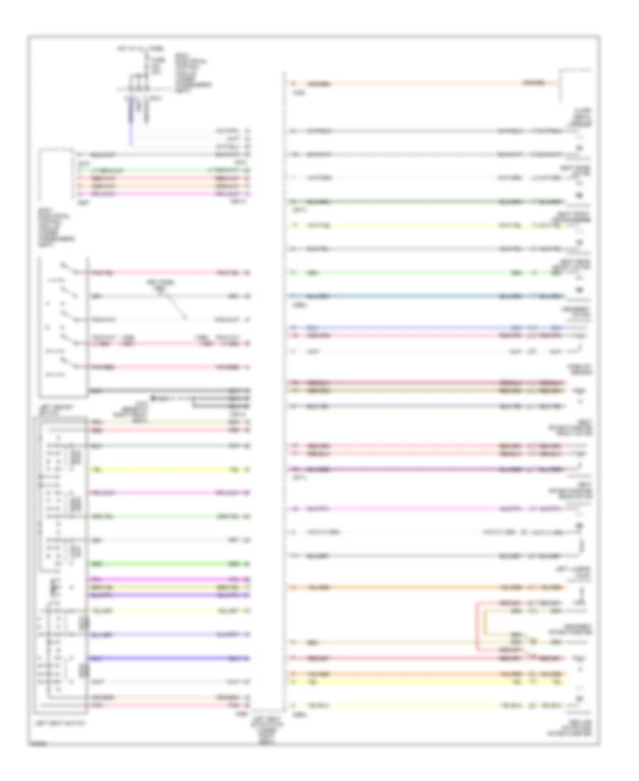
MEMORY SYSTEMS
Memory Mirrors Wiring Diagram (1 of 2) for Land Rover Range Rover SE 1997
List of elements for Memory Mirrors Wiring Diagram (1 of 2) for Land Rover Range Rover SE 1997:
- A/t
- Body electrical control module (under passenger's seat)
- C362
- C626
- C754l
- C755l
- C901
- C997
- Center console switch pack outstation
- Fuse f1 10a
- Fuse f20 30a
- Fuse f22 30a
- Fuse f9 20a
- G103 (beneath right front seat)
- G301 (beneath right front seat)
- G400 (left side of luggage compartment)
- Gear box position switch (top of gear box)
- Hot at all times
- L/r
- Left front door outstation
- Left memory mirror
- Left memory switch
- Left seat outstation (under left seat)
- M/t
- Model only
- Pnk/red
- Red
- Reverse switch (top of gear box)
- U/d
Memory Mirrors Wiring Diagram (2 of 2) for Land Rover Range Rover SE 1997
List of elements for Memory Mirrors Wiring Diagram (2 of 2) for Land Rover Range Rover SE 1997:
- Body electrical control module (under passenger's seat)
- C326
- C754l
- C755r
- C902
- C907
- C912
- C997
- Fuse f20 30a
- Fuse f22 30a
- Fuse f9 20a
- G103 (beneath right front seat)
- G401 (right side of luggage compartment)
- Hot at all times
- L/r
- Model only
- Pnk/red
- Red
- Right front door outstation
- Right memory mirror
- Right memory switch
- Right seat outstation (under right seat)
- U/d
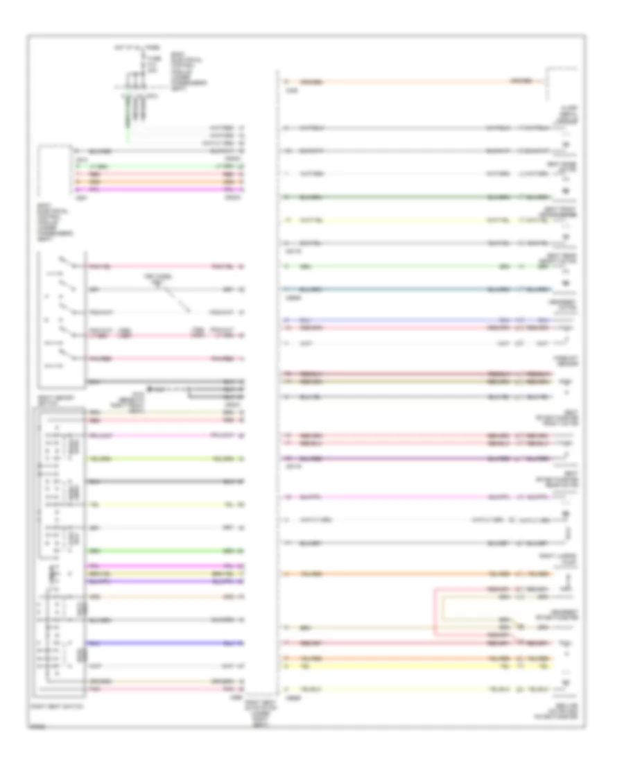
Memory Seat Wiring Diagram (1 of 2) for Land Rover Range Rover SE 1997
List of elements for Memory Seat Wiring Diagram (1 of 2) for Land Rover Range Rover SE 1997:
- (1997)
- (1998)
- 1997 model only
- Alarm aerial module
- Back for/
- Body electrical control module (under passenger's seat)
- C326
- C901a
- C907
- C912
- C962l
- C971l
- C998
- Fore-aft sensor
- Fuse f20 30a
- G103 (beneath right front seat)
- Headrest motor
- Headrest potentiometer
- Hot at all times
- Left lumbar pump
- Left memory switch
- Left seat outstation (under right seat)
- Left seat switch
- Lumbar
- Pnk
- Pnk/red
- Rear up/dn
- Recline motor and potentiometer
- Red
- Rest back
- Rest head
- Seat base motor
- Seat front height motor
- Seat potentiometer front motor
- Seat potentiometer rear motor
- Seat rear height motor
- Up/dn front
Memory Seat Wiring Diagram (2 of 2) for Land Rover Range Rover SE 1997
List of elements for Memory Seat Wiring Diagram (2 of 2) for Land Rover Range Rover SE 1997:
- (1998) (1997)
- 1997 model only
- Alarm aerial module
- Back for/
- Body electrical control module (under passenger's seat)
- C326
- C902a
- C907
- C912
- C962r
- C971r
- C999
- C9o2a
- Fore-aft sensor
- Fuse f10 30a
- G103 (beneath right front seat)
- Headrest motor
- Headrest potentiometer
- Hot at all times
- Lumbar
- Pnk
- Pnk/red
- Rear up/dn
- Recline motor and potentiometer
- Red
- Rest back
- Rest head
- Right lumbar pump
- Right memory switch
- Right seat outstation (under right seat)
- Right seat switch
- Seat base motor
- Seat front height motor
- Seat potentiometer front motor
- Seat potentiometer rear motor
- Seat rear height motor
- Up/dn front
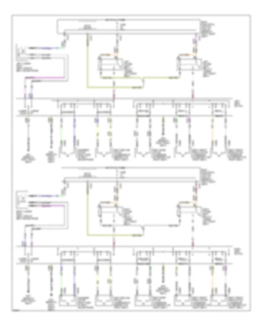
POWER DISTRIBUTION
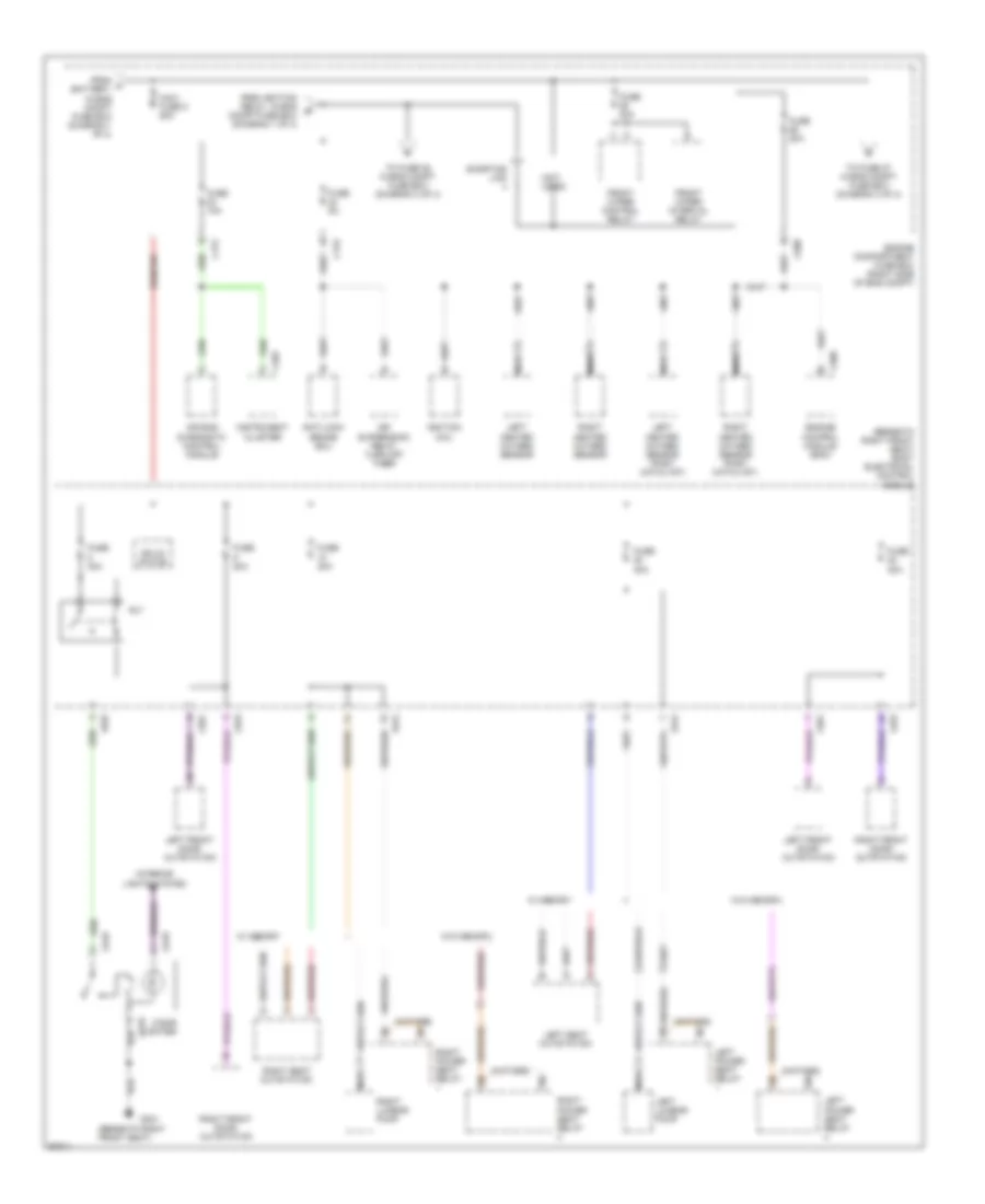
Power Distribution Wiring Diagram (1 of 4) for Land Rover Range Rover SE 1997
List of elements for Power Distribution Wiring Diagram (1 of 4) for Land Rover Range Rover SE 1997:
- "h" gate sensor module
- (1997) (1998)
- (a/t)
- (m/t)
- (not used)
- Abs pump relay
- Air bag diagnostic control module
- Air suspension compressor relay
- Air suspension inhibitor switch
- Auto gear box control unit
- Battery
- Body electrical control module (beneath right front seat)
- C120
- C172
- C173
- C226
- C244
- C256
- C258
- C323
- C324
- C624
- C625
- Center console switch pack outsta- tion
- Clock
- E167
- E252
- Electro- chromic rear view mirror
- Engine compartment fuse box (right side of eng compt)
- Engine controls system
- Footwell lamp 1
- Footwell lamp 2
- From vin
- Fuse
- Fuse 10a
- Fuse 30a
- Fuse 30a 5a
- Generator
- Heating ventilation/ air condi- tioning control unit
- Ignition relay
- Igntion switch
- Iii
- Instrument cluster
- Key illumination
- Maxi fuse 1 60a
- Maxi fuse 2 30a
- Maxi fuse 3 40a
- Maxi fuse 4 60a
- Model only
- Nca
- Radio
- Rear footwell lamp
- Red
- Ride height switch
- Rl10
- Solid state
- Starter relay
- Starter solenoid
- Stop lamp switch
- Sun- visor lamp 1
- Sun- visor lamp 2
- To fuse (diagram 2 of 4)
- To fuse 12 in becm (diagram 4 of 4)
- To fuse 5 in eng compt fuse box (diagram 2 of 4)
- Transfer gear box ecu
Power Distribution Wiring Diagram (2 of 4) for Land Rover Range Rover SE 1997
List of elements for Power Distribution Wiring Diagram (2 of 4) for Land Rover Range Rover SE 1997:
- (beneath right front seat)
- (beneath right front seat) body electrical control module
- (not used)
- 30a
- Air bag diagnostic control module
- Air supsension relay turn off timer
- Anti-lock brake ecu
- C175
- C176
- C323
- C361
- C402
- C508
- C509
- C618
- C619
- C625
- C912
- Cigar lighter
- Engine compartment fuse box (right side of eng compt)
- Engine control module (ecm)
- From a battery, in eng compt fuse box (diagram 1 of 4)
- From ignition relay, in eng b compt fuse box (diagram 1 of 4)
- Front wiper control relay
- Front wiper interval relay
- Fuse
- Fuse 10a
- Fuse 20a
- Fuse 30a
- Fuse 5a
- G301
- Ignition coil
- Instrument cluster
- Interior lights system
- Left front door outstation
- Left heated oxygen sensor
- Left heated oxygen sensor (post catalyst)
- Left lumbar pump
- Left power seat relay
- Left seat outstation
- Maxi fuse 5 60a
- Nca
- Right front door outstation
- Right heated oxygen sensor
- Right heated oxygen sensor (post catalyst)
- Right lumbar pump
- Right power seat relay
- Right seat outstation
- Rl7
- Shorting link
- Solid state
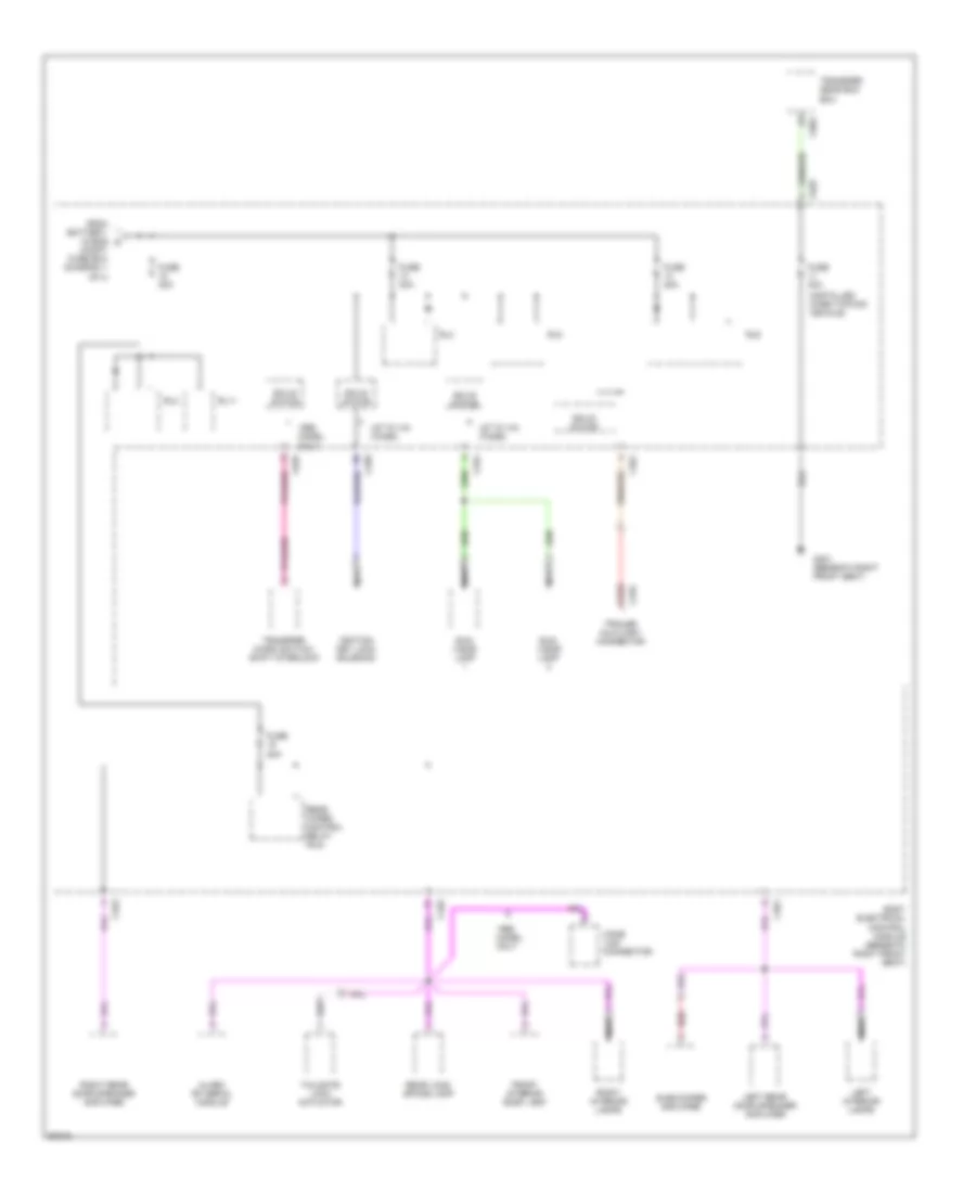
- To fuse 27 in eng compt fuse box (diagram 3 of 4)
- To fuse 35 in eng compt fuse box (diagram 3 of 4)
- W/ memory
- W/o memory
Power Distribution Wiring Diagram (3 of 4) for Land Rover Range Rover SE 1997
List of elements for Power Distribution Wiring Diagram (3 of 4) for Land Rover Range Rover SE 1997:
- (not used)
- (right side of engine compt) engine compartment fuse box
- A/c condenser fan 1 relay
- A/c condenser fan 2 relay
- Abs power relay
- Abs pump relay
- Air suspension delay turn off timer
- Air suspension power relay
- Auxiliary power 1 relay
- Auxiliary power 2 relay
- Battery backed up alarm sounder
- C172
- C173
- C174
- C177
- C231
- C244
- C508
- Data link connection (obdii)
- Engine main control relay
- From e battery in eng compt fuse box (diagram 2 of 4)
- From ignition relay, in eng compt fuse box (diagram 2 of 4)
- From vin
- Fuel pump relay
- Fuse 10a
- Fuse 20a
- Fuse 25a
- Fuse 30a
- Fuse 5a
- Headlamps washer/wiper relay
- Heating ventilation/ air conditioning control unit (hevac)
- Horn relay
- Ignition key lock solenoid
- Left condenser fan motor
- Left headlamp wiper motor
- Left heated windshield relay
- Nca
- Right headlamp wiper motor
- Right heated windshield relay
- Shorting link
- Spare relay
- Starter relay
- Starter solenoid
- Up to vin
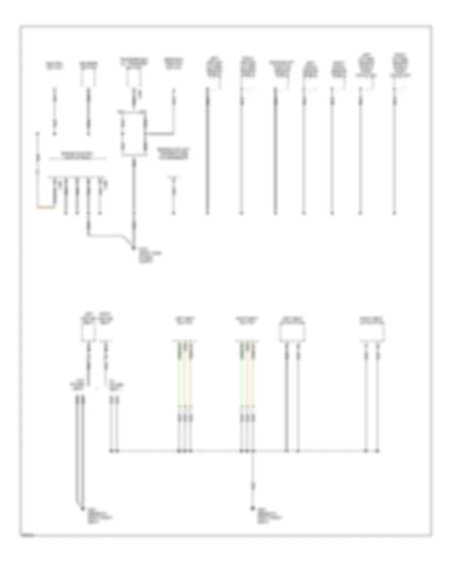
Power Distribution Wiring Diagram (4 of 4) for Land Rover Range Rover SE 1997
List of elements for Power Distribution Wiring Diagram (4 of 4) for Land Rover Range Rover SE 1997:
- (installed when towing vehicle)
- 20a
- 30a
- Alarm rf aerial module
- Body electrical control module (beneath right front seat)
- C258
- C323
- C324
- C325
- C361
- C376
- C603
- C625
- Compt fuse box (diagram 1 of 4)
- From battery, in eng c
- Front interior roof lamp
- Fuse
- Fuse 20a
- Fuse 30a
- G301 (beneath right front seat)
- Home link connector
- Ignition key lock solenoid
- Left interior lamps
- Left rear door speaker amplifier
- Model only
- Nca
- Rear load space lamp
- Rear wiper control relay (rl8)
- Red
- Right interior lamps
- Right rear door speaker amplifier
- Rl11
- Rl2
- Rl3
- Rl5
- Rl6
- Solid state
- Subwoofer amplifier
- Sun- visor lamp
- Tailgate lock actuator
- Trailer auxiliary connector
- Transfer gear box ecu
- Transfer micro switch/ shift interlock
- Up to vin
POWER DOOR LOCKS
Power Door Lock Wiring Diagram (1 of 2) for Land Rover Range Rover SE 1997
List of elements for Power Door Lock Wiring Diagram (1 of 2) for Land Rover Range Rover SE 1997:
- (behind right footwell trim panel)
- (left front side of luggage compt)
- (left side of luggage compt)
- (left side of luggage compt) g400
- (right front side of luggage compt)
- (right side of luggage compt)
- (right side of luggage compt) g401
- Alarm rf aerial module (right side of luggage compt)
- Antenna
- Body electrical control module (beneath right front seat)
- C112
- C257
- C323
- C325
- C326
- C361
- C362
- C507
- C755l
- C755r
- C758l
- C758r
- C762l
- C762r
- C763l
- C763r
- C901a
- C907
- Cdl motor
- Cdl sw
- Door ajar sw
- Engine control module (right side of eng compt)
- Fuse 20a
- Fuse 30a
- G203
- G400
- G401
- Hot at all times
- Ignition switch
- Iii
- Key sw
- Left front door lock actuator (front door trim panel)
- Left front door outstation (behind front door trim panel)
- Left front window motor (behind front door trim panel)
- Left rear window motor (behind front door trim panel)
- Nca
- Red
- Right front door lock actuator (front door trim panel)
- Right front door outstation (behind front door trim panel)
- Right front window motor (behind front door trim panel)
- Right rear window motor (behind front door trim panel)
- Solid state
- Superlock
- Ultrasonic module (top of left "b "pillar)
- W/ memory seat
Power Door Lock Wiring Diagram (2 of 2) for Land Rover Range Rover SE 1997
List of elements for Power Door Lock Wiring Diagram (2 of 2) for Land Rover Range Rover SE 1997:
- (left side of luggage compt)
- (right rear of eng compt)
- (right side of eng compt)
- (right side of luggage compt)
- Alarm sounder (right side of eng compt)
- Battery back up alarm sounder (right side of eng compt)
- Body electrical control module (beneath right front seat)
- C114
- C120
- C133
- C255
- C256
- C258
- C323
- C324
- C325
- C326
- C361
- C362
- C625
- Cdl motor
- Closed on impack
- Door ajar sw
- Engine controls system
- Exterior lights system (side lamps)
- Exterior lights system (turn/ hazard lamps)
- Fuel pump
- Fuel tank module (top of fuel tank)
- G101
- G105
- G105 (right rear of eng compt)
- G203 (right footwell trim panel)
- G400
- G401
- G401 (right side of luggage compt)
- Headlamp system
- Hood switch (near right horn)
- Inertia fuel shut-off switch (behind right footwell trim panel)
- Interior lights system
- Key-in switch (in steering lolumn)
- Left rear door lock actuator (top of left rear door)
- Nca
- Passive immobilization coil (underside of steering column)
- Pnk
- Red
- Right rear door lock actuator (top of right rear door)
- Right tailgate lamps
- Solid state
- Sunroof anti-trap (front center of roof)
- Superlock
- Tailgate switch (center of tailgate)
- Theft alarm led
- W/ battery back up alarm sounder
- W/o battery back up alarm sounder
POWER MIRRORS
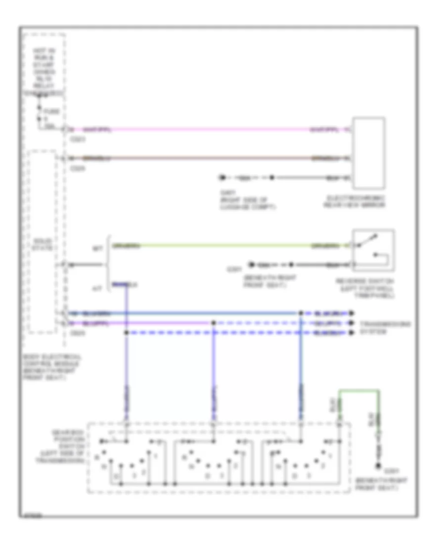
Electrochromic Mirror Wiring Diagram for Land Rover Range Rover SE 1997
List of elements for Electrochromic Mirror Wiring Diagram for Land Rover Range Rover SE 1997:
- (beneath right front seat)
- A/t
- Body electrical control module (beneath right front seat)
- C323
- C326
- C626
- Electrochromic rear view mirror
- Fuse 10a
- G301
- G401 (right side of luggage compt)
- Gear box position switch (left side of transmission)
- Hot in run & start (when rl10 relay energized)
- M/t
- Reverse switch (left footwell trim panel)
- Solid state
- Transmissions system
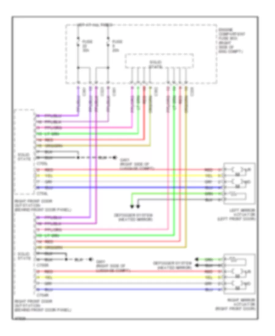
Power Mirrors Wiring Diagram for Land Rover Range Rover SE 1997
List of elements for Power Mirrors Wiring Diagram for Land Rover Range Rover SE 1997:
- C323
- C326
- C361
- C362
- C754l
- C754r
- C755l
- C755r
- Defogger system (heated mirror)
- Engine compartent fuse box (right side of eng compt)
- Fuse 20a
- Fuse 30a
- G401 (right side of luggage compt)
- Hot at all times
- L/r
- Left mirror actuator (left front door)
- Red
- Right front door outstation (behind front door panel)
- Right mirror actuator (right front door)
- Solid state
- U/d
POWER SEATS
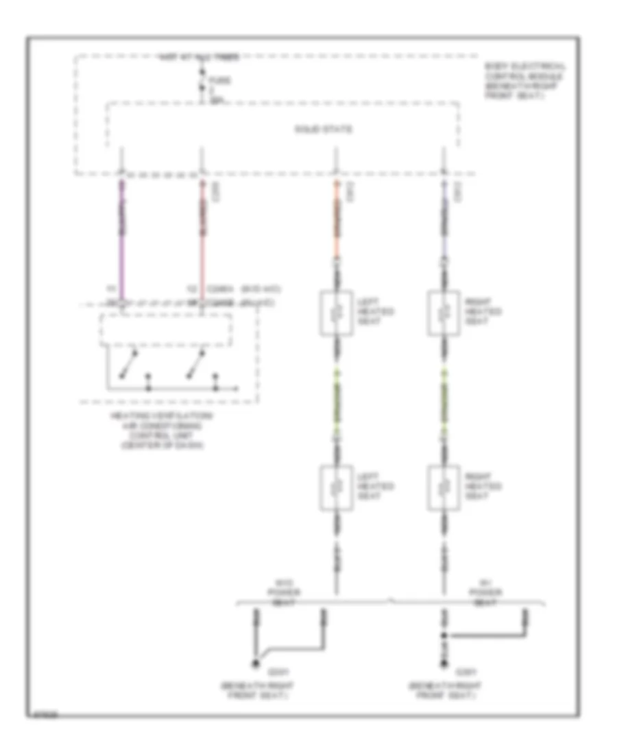
Heated Seats Wiring Diagram for Land Rover Range Rover SE 1997
List of elements for Heated Seats Wiring Diagram for Land Rover Range Rover SE 1997:
- (beneath right front seat)
- (w/ a/c)
- (w/o a/c)
- Body electrical control module (beneath right front seat)
- C246a
- C246b
- C255
- C912
- Fuse 30a
- G301
- Heating ventilation/ air conditioning control unit (center of dash)
- Hot at all times
- Left heated seat
- Nca
- Right heated seat
- Solid state
- W/ power seat
- W/o power seat
Power Seats Wiring Diagram for Land Rover Range Rover SE 1997
List of elements for Power Seats Wiring Diagram for Land Rover Range Rover SE 1997:
- Backrest
- Backward
- Body electrical control module (beneath right front seat)
- C912
- C956l
- C956r
- C957l
- C957r
- C9595
- C959l
- C9605
- C960l
- C964r
- C965l
- C965r
- Forward
- Front d
- Front u
- Fuse 30a
- G301 (beneath right front seat)
- Headrest
- Headrest motor (right side of seat squab frame)
- Hot at all times
- Left lumbar pump (right side of seat squab frame)
- Left power seat relay 1 (under left front seat)
- Left power seat relay 2 (under left front seat)
- Left seat switch
- Lumbar down
- Lumbar up
- Nca
- Pnk
- Rear d
- Rear u
- Red
- Right lumbar pump (right side of seat squab frame)
- Right power seat relay 1 (under left front seat)
- Right power seat relay 2 (under left front seat)
- Right seat switch
- Seat base motor (underside of respective front seat)
- Seat height front motor (underside of respective front seat)
- Seat height rear motor (underside of respective front seat)
- Seat recline motor (underside of respective front seat)
- Solid state
POWER TOP/SUNROOF
Power Top/Sunroof Wiring Diagrams for Land Rover Range Rover SE 1997
List of elements for Power Top/Sunroof Wiring Diagrams for Land Rover Range Rover SE 1997:
- (beneath right front seat)
- Alarm rf aerial module (right side of laggage compt)
- Antenna
- Body electrical control module (beneath right front seat)
- C323
- C324
- C325
- C326
- C625
- C626
- Center console switch pack outstation (in center console)
- Fuse 10a
- Fuse 20a
- G301
- G301 (beneath right front seat)
- G401 (right side of luggage compt)
- Hot at all times
- Interior lights system
- Red
- Rl3
- Rl5
- Solid state
- Sunroof anti-trap
- Sunroof backward
- Sunroof forward
POWER WINDOWS
Power Window Wiring Diagram for Land Rover Range Rover SE 1997
List of elements for Power Window Wiring Diagram for Land Rover Range Rover SE 1997:
- (beneath right front seat)
- (left front side of luggage compt)
- (left side of luggage compt) g400
- (right front side of luggage compt)
- (right side of luggage compt) g401
- Alarm rf aerial module (right side of luggage compt)
- Antenna
- Body electrical control module (beneath right front seat)
- C323
- C325
- C326
- C361
- C362
- C625
- C626
- C755l
- C755r
- Center console switch pack outstation (in center console)
- Fuse 10a
- Fuse 20a
- Fuse 30a
- G301
- G400
- G401
- G401 (right side of luggage compt)
- Hot at all times
- Interior lights system
- Left front door outstation (behind front door trim panel)
- Left front window motor (behind front door trim panel)
- Left rear window door switch
- Left rear window motor (behind front door trim panel)
- Lf dn
- Lf up
- Lr dn
- Lr up
- Rear wnd isolation
- Red
- Rf dn
- Rf up
- Right front door outstation (behind front door trim panel)
- Right front window motor (behind front door trim panel)
- Right rear window door switch
- Right rear window motor (behind front door trim panel)
- Rr dn
- Rr up
- Solid state
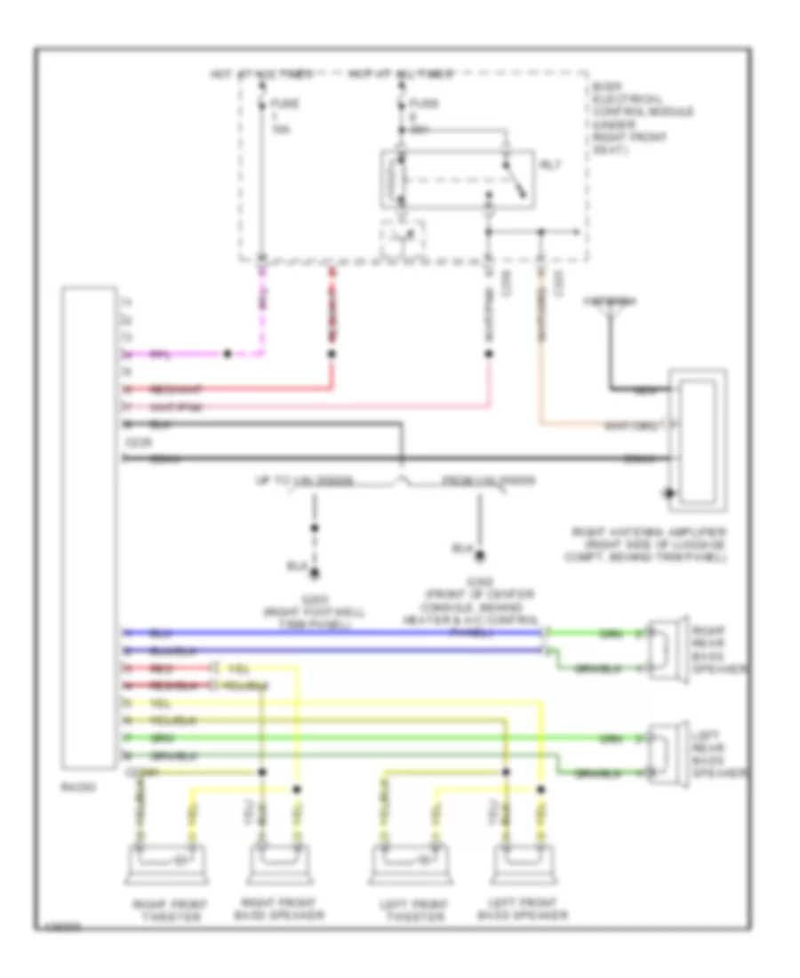
RADIO
Radio Wiring Diagrams, Base for Land Rover Range Rover SE 1997
List of elements for Radio Wiring Diagrams, Base for Land Rover Range Rover SE 1997:
- Antenna
- Body electrical control module (under right front seat)
- C224a
- C226
- C258
- C325
- Coax
- Console, behind heater & a/c control panel)
- From vin 359269
- Fuse 10a
- Fuse 30a
- G203 (right footwell trim panel)
- G302 (front of center
- Hot at all times
- Left front bass speaker
- Left front tweeter
- Left rear bass speaker
- Nca
- Radio
- Red
- Right antenna amplifier (right side of luggage compt, behind trim panel)
- Right front bass speaker
- Right front tweeter
- Right rear bass speaker
- Rl7
- Up to vin 359268
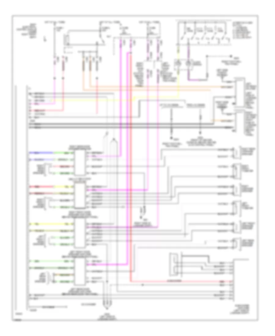
Radio Wiring Diagrams, Highline for Land Rover Range Rover SE 1997
List of elements for Radio Wiring Diagrams, Highline for Land Rover Range Rover SE 1997:
- (behind rear door trim panel)
- (left side of luggage compt, behind trim panel)
- (right footwell trim panel)
- (right side of luggage compt)
- 15 k homs
- 4.7 k homs
- Body electrical control module (under right front seat)
- C224b
- C226
- C258
- C323
- C325
- C361
- C755l
- C755r
- Cd changer
- Clock spring
- Coax
- Din cable
- From vin 359269
- Fuse 1 10a
- Fuse 20a
- Fuse 8 30a
- G203
- G302 (front of center console, behind heater & a/c control panel)
- G400 (left side of luggage compt)
- G401
- Homs
- Hot at all times
- Left antenna aplifier
- Left front bass speaker
- Left front door out- c755l
- Left front door speaker amplifier (behind rear door trim panel)
- Left front midrange speaker
- Left front tweeter
- Left rear bass speaker
- Left rear door speaker amplifier (behind rear door trim panel)
- Left rear midrange speaker
- Left side window antenna
- Nca
- Radio
- Red
- Right antenna aplifier (right side of luggage compt, behind trim panel)
- Right front bass speaker
- Right front door out- station (behind front door trim panel)
- Right front door speaker amplifier (behind rear door trim panel)
- Right front tweeter
- Right midrange speaker
- Right rear bass speaker
- Right rear door speaker amplifier
- Right rear midrange speaker
- Right side window antenna
- Rl7
- Station (behind front door trim panel)
- Steering wheel switch 1- increase 2- decrease 3- mode select 4- volume up 5- volume down
- Subwoofer
- Subwoofer amplifier (left side of luggage compt)
- Up to vin 359268
Radio Wiring Diagrams, Midline for Land Rover Range Rover SE 1997
List of elements for Radio Wiring Diagrams, Midline for Land Rover Range Rover SE 1997:
- Antenna
- Body electrical control module (under right front seat)
- C224a
- C226
- C258
- C325
- Capacitor
- Coax
- Console, behind heater & a/c control panel)
- From vin 359269
- Fuse 10a
- Fuse 30a
- G203 (right footwell trim panel)
- G302 (front of center
- Hot at all times
- Left front bass speaker
- Left front midrange speaker
- Left front tweeter
- Left rear bass speaker
- Left rear midrange speaker
- Nca
- Radio
- Red
- Right antenna amplifier (right side of luggage compt, behind trim panel)
- Right front bass speaker
- Right front midrange speaker
- Right front tweeter
- Right rear bass speaker
- Right rear midrange speaker
- Rl 7
- Up to vin 359268
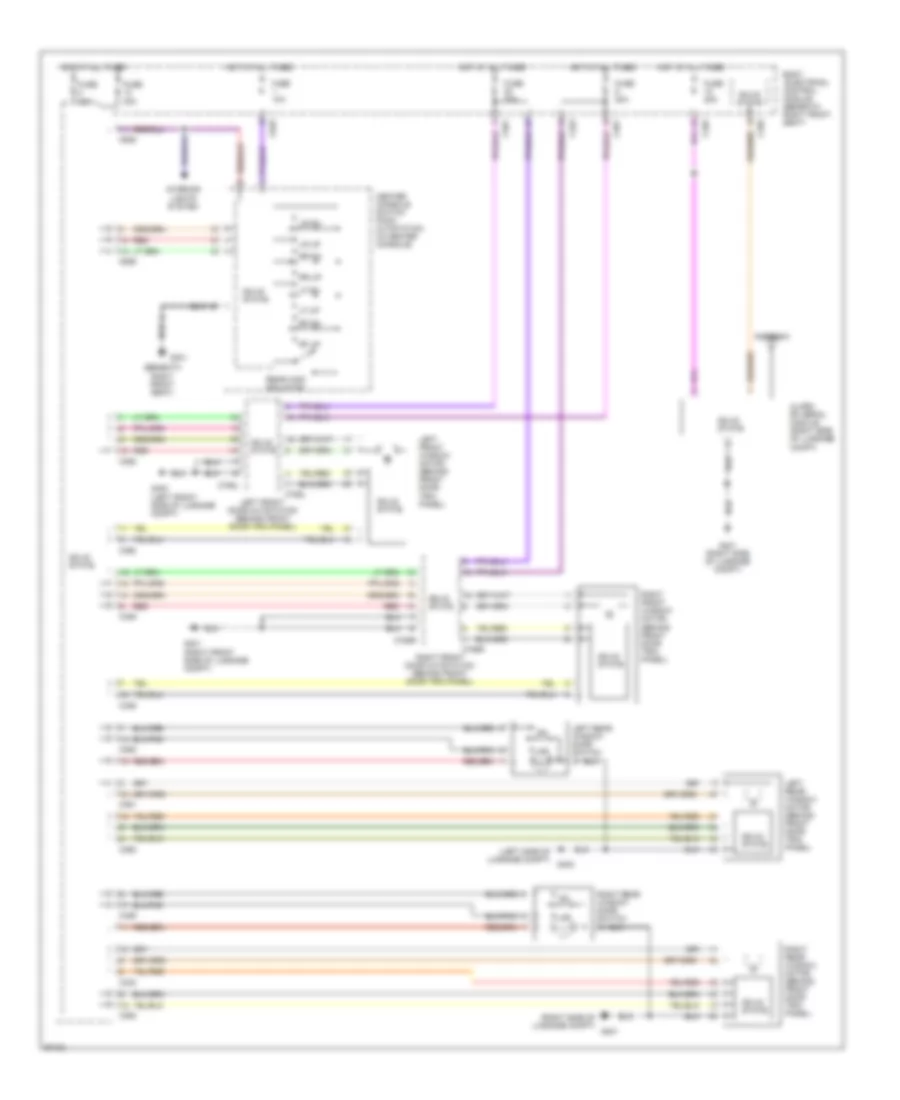
SHIFT INTERLOCKS
Shift Interlock Wiring Diagram for Land Rover Range Rover SE 1997
List of elements for Shift Interlock Wiring Diagram for Land Rover Range Rover SE 1997:
- (beneath right front seat)
- (right footwell trim panel)
- (right footwell trim panel) g203
- (right of steering column) ignition key-lock solenoid
- (right of steering column) key-in switch
- Body electrical control module (beneath right front seat)
- C172
- C255
- C256
- C258
- C625
- C626
- From vin
- Fuse 10a
- Fuse 20a
- G203
- G301
- Gear box position switch (left side of transmission)
- Hot at all times
- Hot in run & start (when rl10 relay energized)
- I ii
- Ignition switch
- Iii
- Nca
- Park switch
- Shift lock solenoid
- Solid state
- Stop lamp switch (on brake pedal support)
- Transfer micro switch
- Transfer micro switch/ shift lock solenoid (beneath center console)
- Transmissions system
- Transmissions system (transfer gear box)
- Up to vin
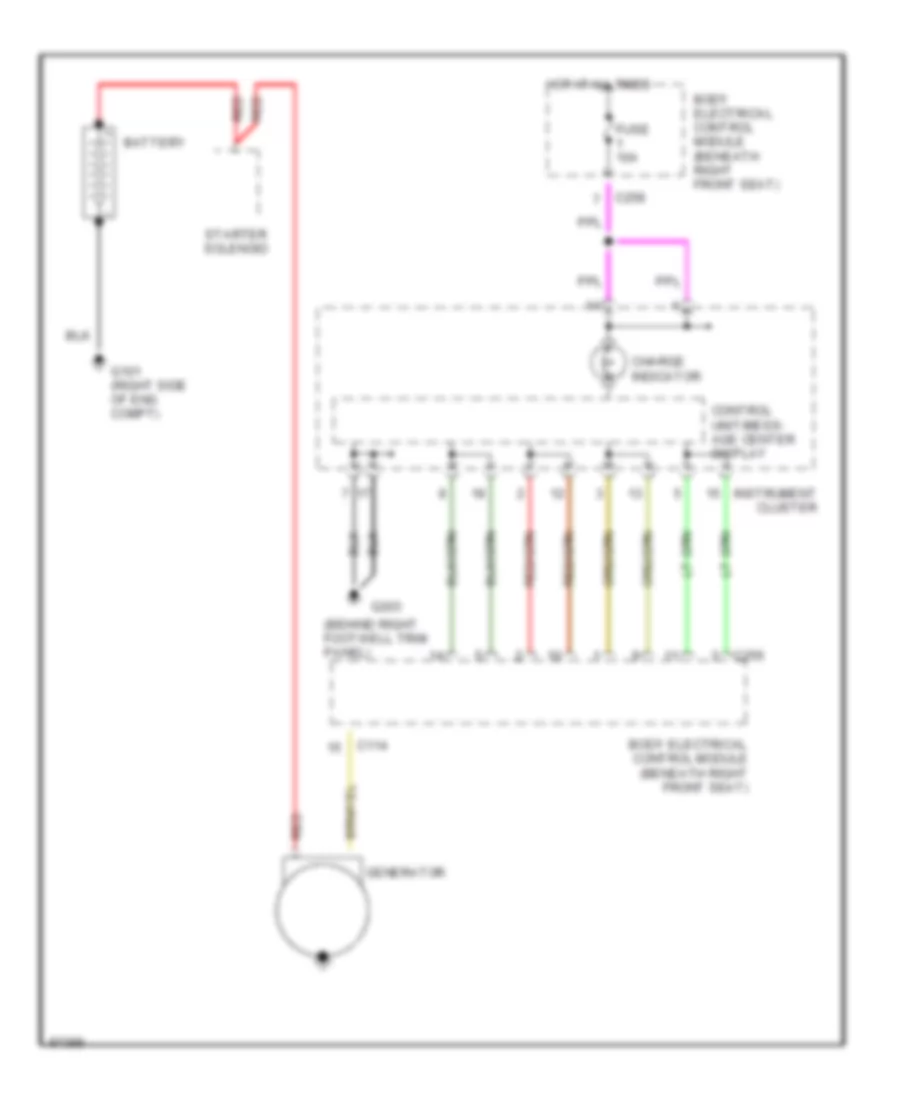
STARTING/CHARGING
Charging Wiring Diagram for Land Rover Range Rover SE 1997
List of elements for Charging Wiring Diagram for Land Rover Range Rover SE 1997:
- (behind right footwell trim panel)
- (right side of eng compt)
- Battery
- Body electrical control module (beneath right front seat)
- C114
- C256
- C258
- Charge indicator
- Control unit/mess- age center display
- Fuse 10a
- G101
- G203
- Generator
- Hot at all times
- Instrument cluster
- Red
- Starter solenoid
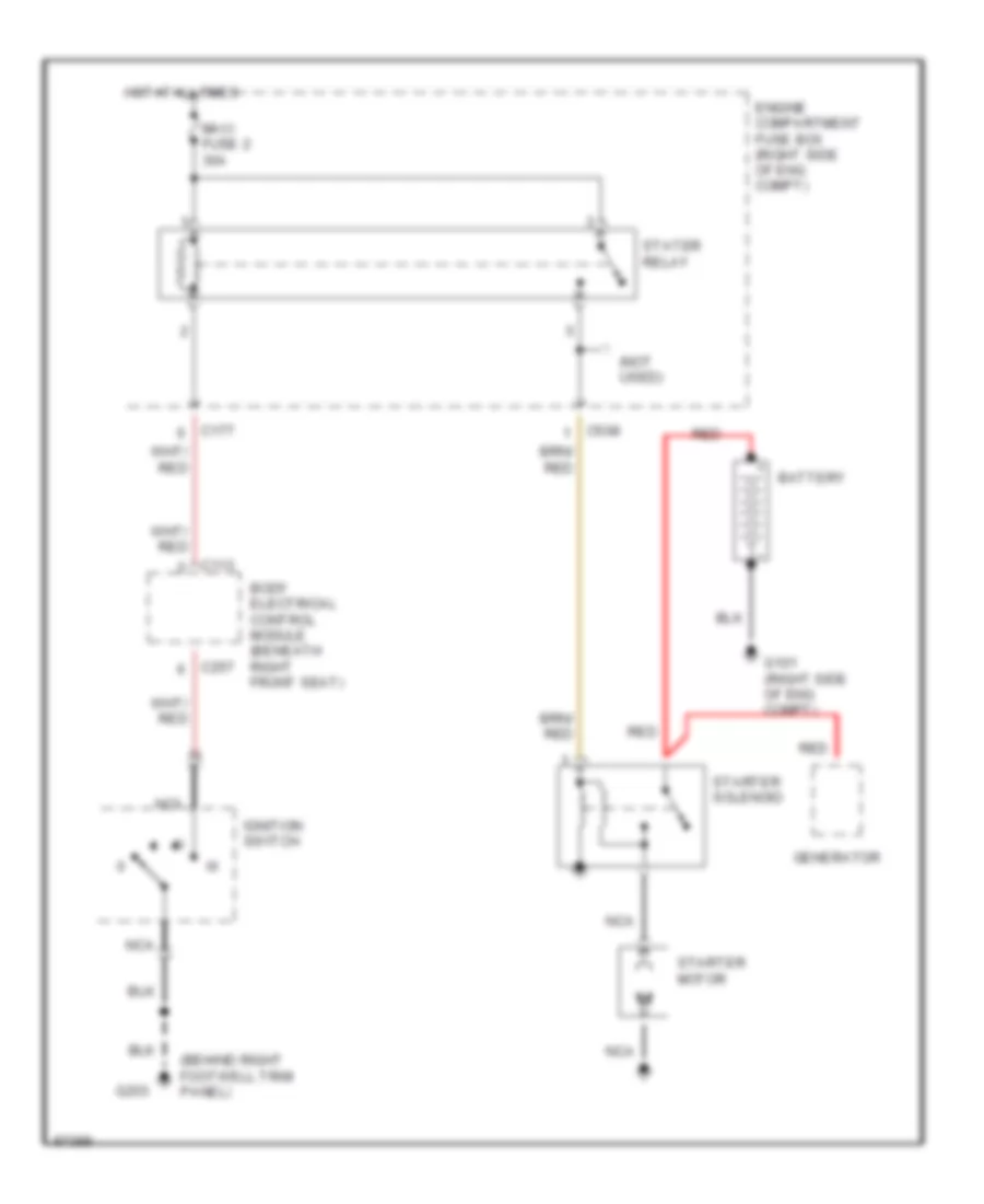
Starting Wiring Diagram for Land Rover Range Rover SE 1997
List of elements for Starting Wiring Diagram for Land Rover Range Rover SE 1997:
- (behind right footwell trim panel)
- (not used)
- Battery
- Body electrical control module (beneath right front seat)
- C113
- C177
- C257
- C508
- Engine compartment fuse box (right side of eng compt)
- G101 (right side of eng compt)
- G203
- Generator
- Hot at all times
- Ignition switch
- Iii
- Maxi fuse 2 30a
- Nca
- Red
- Starter motor
- Starter solenoid
- Stater relay
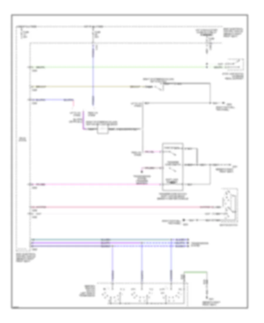
TRANSMISSION
4WD Wiring Diagram for Land Rover Range Rover SE 1997
List of elements for 4WD Wiring Diagram for Land Rover Range Rover SE 1997:
- (beneath right front seat)
- (beneath right front seat) g301
- (from vin 370859 only)
- (installed when towing)
- (m/t only)
- (right side of eng compt)
- (under center console)
- 0=open 1=close
- A/t
- Automatic gear box
- Body electrical control module (under right front seat)
- C507
- C624
- C625
- C626
- Change sw
- Engine control module (ecm) (right front of eng compt, behind battery)
- Fuse 30a
- Fuse 6 10a
- G103
- G301
- G301 (beneath right front seat)
- Gearbox position switch (left side of transmission)
- Hi mode
- Hot at all times
- Hot in run & start
- Illum
- Instrument cluster sytsem
- Left hi mode
- Left stop
- Lo mode
- Lo range sw
- Low range ind
- M/t
- Nca
- Neutral mode
- Neutral switch (left side of trans- mission)
- Park sw
- Pnk/red
- Right hi mode
- Right stop
- Shift interlock system
- Shit lock lock sol
- Transfer gear box ecu (under left front seat)
- Transfer box driver/ motor/encoder (on rear of transfer box)
- Transfer micro switch/shift lock solenoid (a/t only)
- Transfer switch manual (m/t only) (center of facia)
- Vehicle speed sensor (on rear of tranfer box)
- Zone 1
- Zone 2
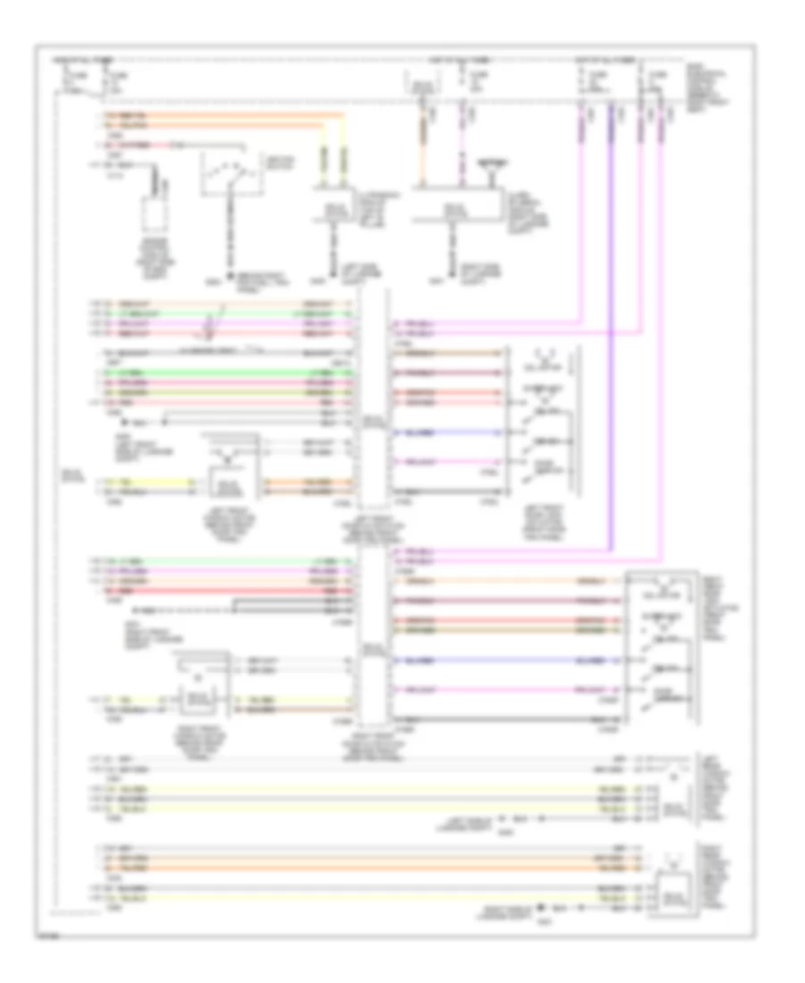
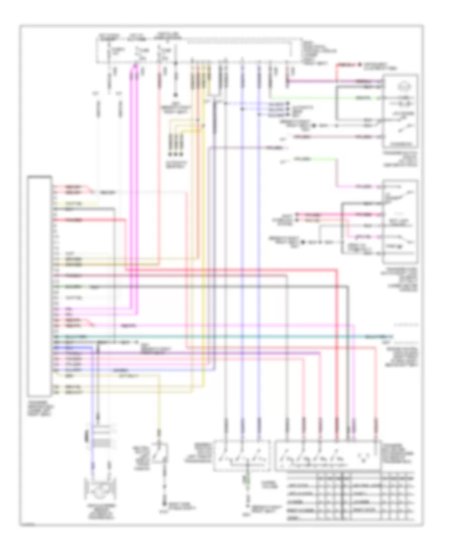
A/T Wiring Diagram for Land Rover Range Rover SE 1997
List of elements for A/T Wiring Diagram for Land Rover Range Rover SE 1997:
- "h" sensor module (in center console)
- (1998) (1997)
- (beneath right front seat)
- (beneath right front seat) g301
- (not used)
- (right side of eng compt)
- Auto gear box control unit (under left front seat)
- Body electrical control module (under right front seat)
- C505
- C507
- C509
- C625
- C626
- Converter lock up solenoid
- Engine control module (ecm) (right front of eng compt, behind battery)
- Engine coolant temperature sensor (left side of eng)
- Fuse 5a 30a
- Fuse 6 10a
- G103
- G301
- Gear box case
- Gear box position switch (left side of transmission)
- Gnd
- Hot at all times
- Hot in run & start
- Ign
- Illum
- Interior lights system
- Manual
- Mes1
- Mes2
- Mode (mes) sw
- Mv1 sole- noid
- Mv2 sole- noid
- Nca
- Output shaft speed sensor
- Pnk
- Pressure regulator solenoid
- Red
- S/e/m
- Sport
- Throttle position sensor (on throttle body)
- Transfer gear box ecu (under left front seat)
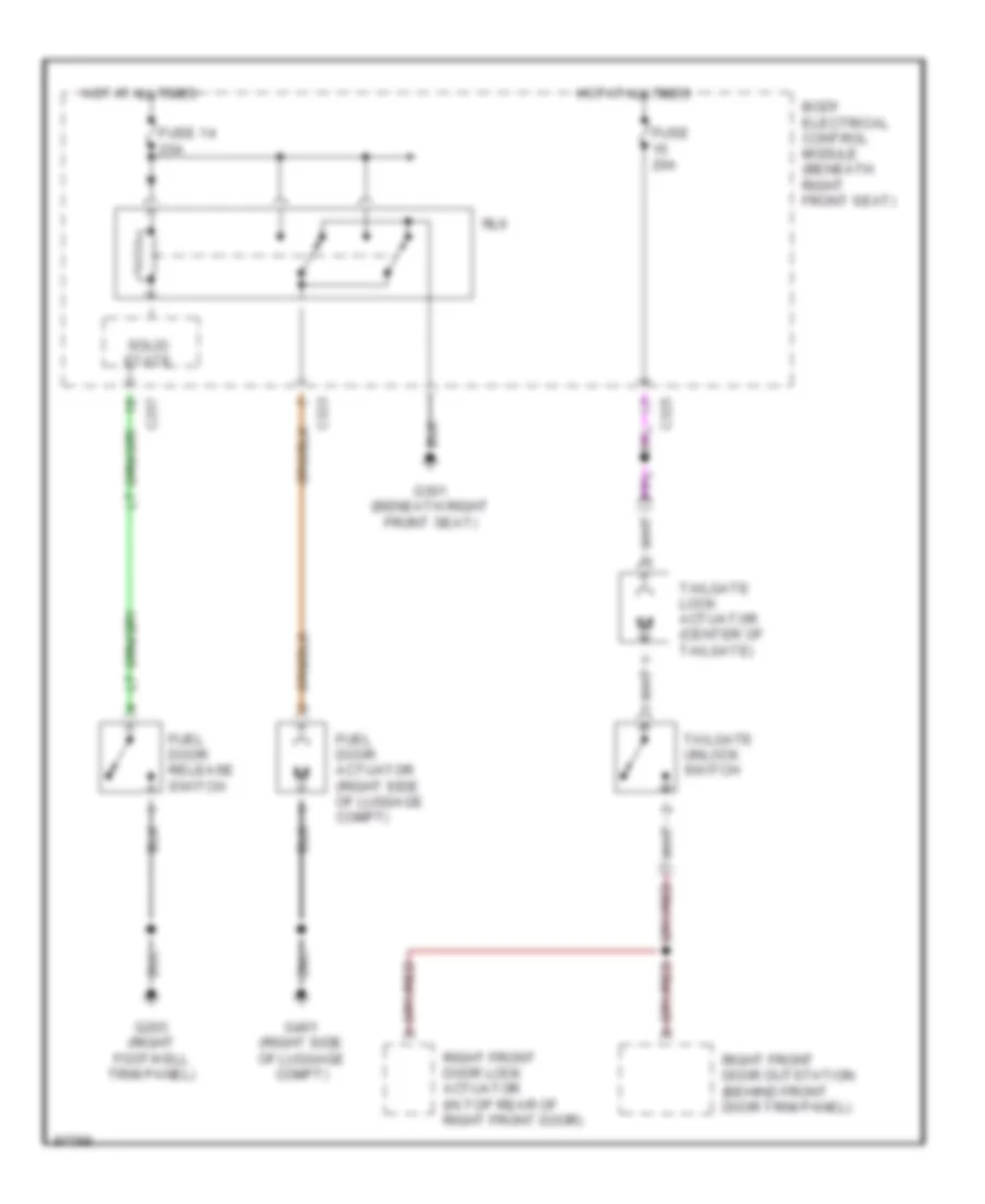
TRUNK, TAILGATE, FUEL DOOR
Trunk, Tailgate, Fuel Door Wiring Diagrams for Land Rover Range Rover SE 1997
List of elements for Trunk, Tailgate, Fuel Door Wiring Diagrams for Land Rover Range Rover SE 1997:
- Body electrical control module (beneath right front seat)
- C257
- C323
- C325
- Fuel door actuator (right side of luggage compt)
- Fuel door release switch
- Fuse 14 20a
- Fuse 20a
- G203 (right footwell trim panel)
- G301 (beneath right front seat)
- G401 (right side of luggage compt)
- Hot at all times
- Right front door lock actuator (in top rear of right front door)
- Right front door outstation (behind front door trim panel)
- Rl6
- Solid state
- Tailgate lock actuator (center of tailgate)
- Tailgate unlock switch
WARNING SYSTEMS
Warning System Wiring Diagrams for Land Rover Range Rover SE 1997
List of elements for Warning System Wiring Diagrams for Land Rover Range Rover SE 1997:
- (behind right foowell trim panel)
- Body electrical control module (beneath right front seat)
- Buzzer
- C242
- C255
- C256
- C626
- Control unit/mess- age center display
- Driver's seat buckle switch (inside driver's seat belt buckle switch assembly)
- Fuse 10a
- G203
- G203 (right footwell trim panel)
- G301 (beneath right front seat)
- Hot at all times
- Instrument cluster
- Key-in switch (right of steering column)
- Nca
- Seat belt warning ind
WIPER/WASHER
Front & Rear Wiper/Washer Wiring Diagram for Land Rover Range Rover SE 1997
List of elements for Front & Rear Wiper/Washer Wiring Diagram for Land Rover Range Rover SE 1997:
- (beneath right front seat)
- (left rear corner of eng compt) front wiper motor
- (left rear of eng compt)
- A/t
- Anti-lock brake system ecu (right side of dash)
- Body electrical control module (beneath right front seat)
- C113
- C114
- C120
- C172
- C175
- C257
- C325
- C326
- Engine compartment fuse box (right front of eng compt)
- Front washer
- Front wiper control relay
- Front wiper interval relay
- Front wiper switch 1
- Front wiper switch 2
- Front wiper switch 3
- Fuse 20a
- Fuse 30a
- G101 (right side of eng compt)
- G104
- G105 (right rear of eng compt)
- G203 (right footwell trim panel)
- G301
- G301 (beneath right front seat)
- G401 (right side of luggage compt)
- Gear box position switch (left side of transmission)
- Hot at all times
- Intermittent
- M/t
- Nca
- Rear washer
- Rear window washer pump (behind right side of front bumper)
- Rear window wiper motor (top center of windshield, behind trim panel)
- Rear wiper
- Rear wiper control relay (rl8)
- Reverse switch (left footwell trim panel)
- Solid state
- Transmissions system
- Washer/wiper switch
- Windshield wiper motor (behind right side of front bumper)
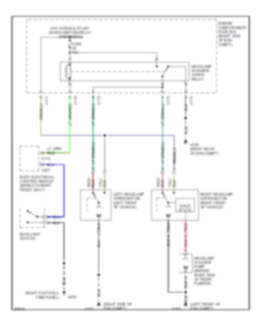
Headlamp Wiper/Washer Wiring Diagram for Land Rover Range Rover SE 1997
List of elements for Headlamp Wiper/Washer Wiring Diagram for Land Rover Range Rover SE 1997:
- (left front of eng compt)
- (right footwell trim panel)
- (right side of eng compt)
- Body electrical control module (beneath right front seat)
- C113
- C172
- C175
- C176
- C177
- C257
- Engine compartment fuse box (right side of eng compt)
- Fuse 10a
- G100
- G101
- G105 (right rear of eng compt)
- G203
- Headlamp washer pump (behind right side of front pumper)
- Headlamp washer/ wiper relay
- Hot in run & start (when ignition relay energized)
- Left headlamp wiper motor (left front of vehicle)
- Main light switch
- Red
- Right headlamp wiper motor (right front of vehicle)
- Solid state

 Čeština
 Dansk
Dansk Deutsch
 Ελληνικά
 English
 Español
 Suomi
Suomi Français
 Français
 עברית
עברית Hrvatski
 Magyar
 Italiano
 日本語
日本語 한국어
한국어 Nederlands
 Polski
 Português
 Português
 Română
 Русский
 Slovenčina
 Slovenščina
 Svenska
 Türkçe
 中文 (中国)