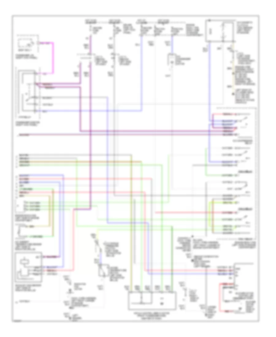
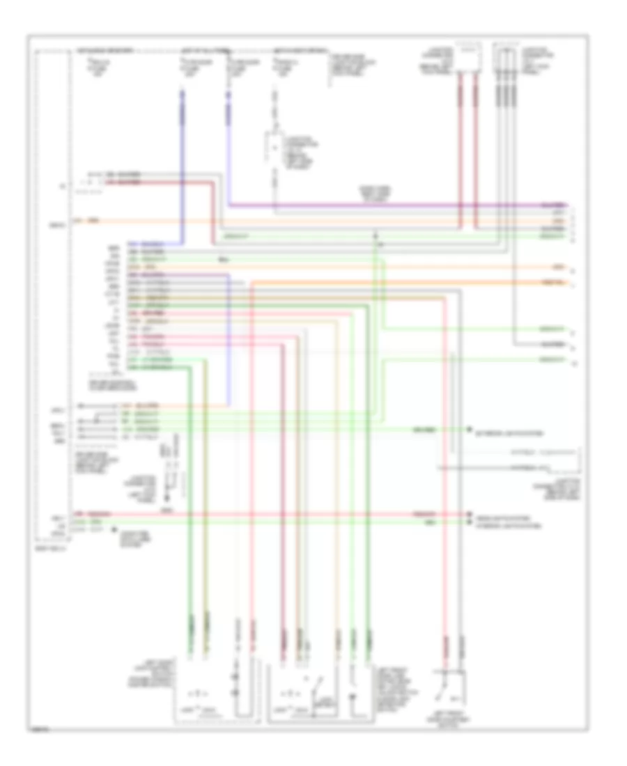
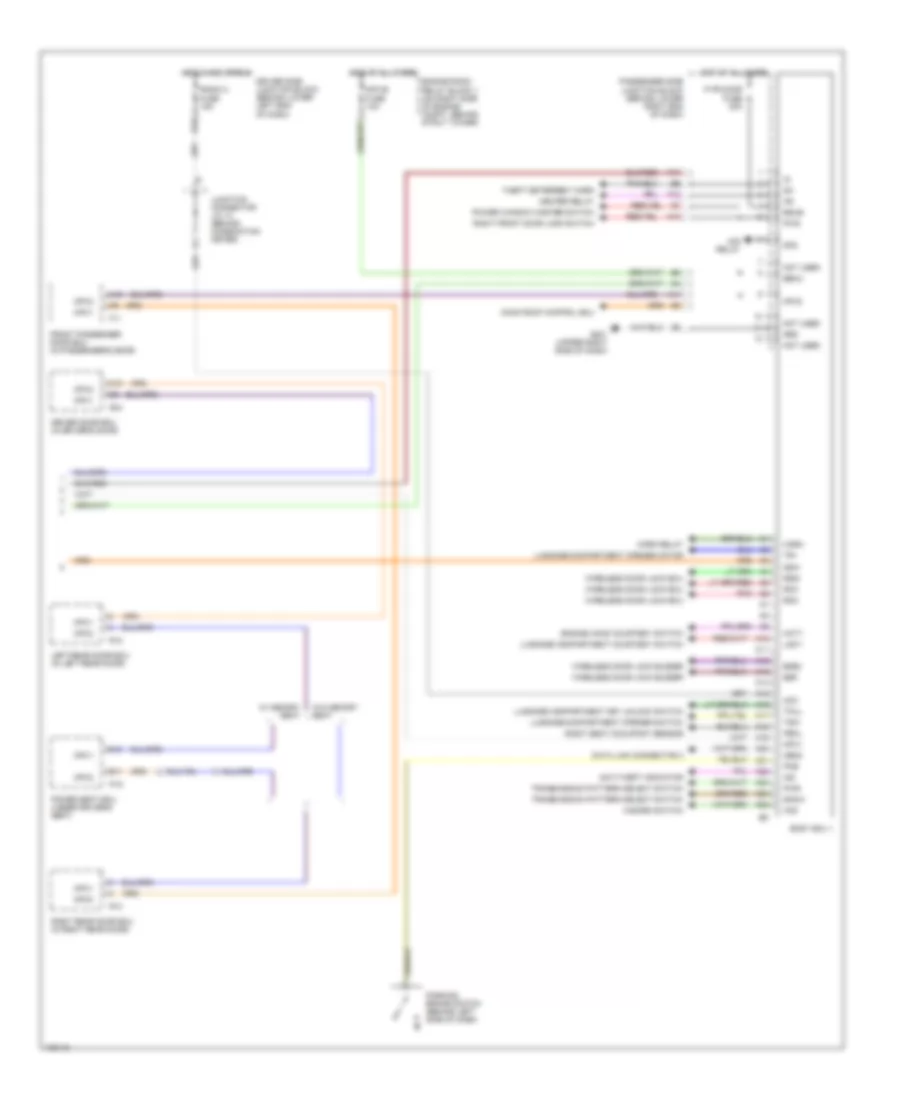
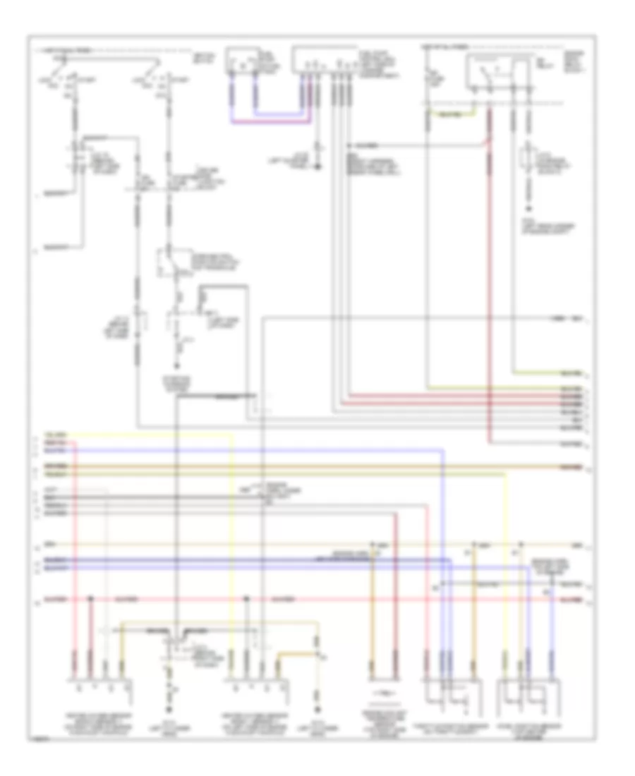
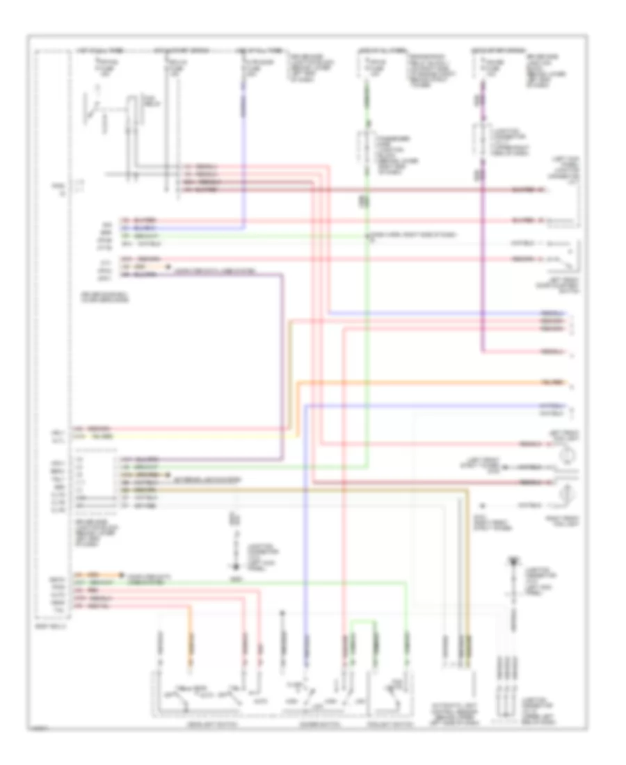
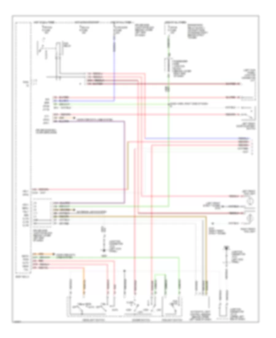
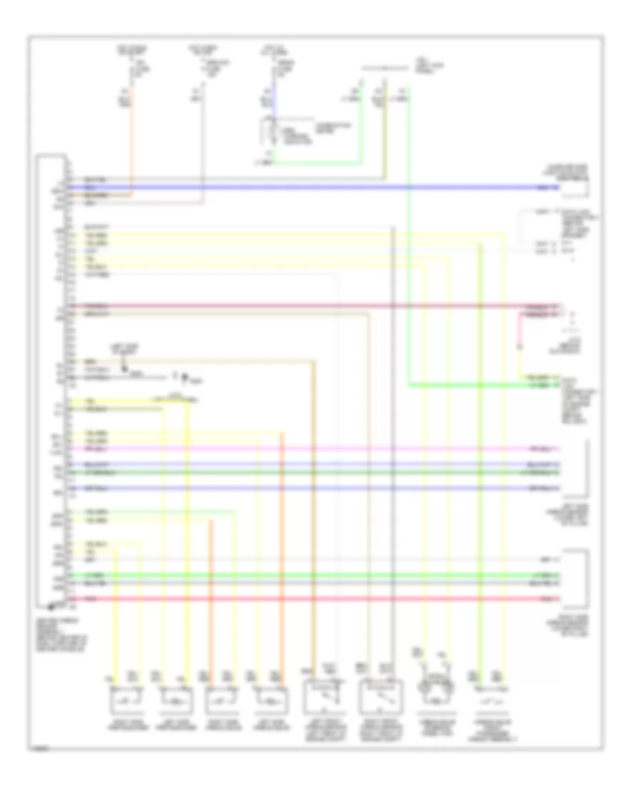
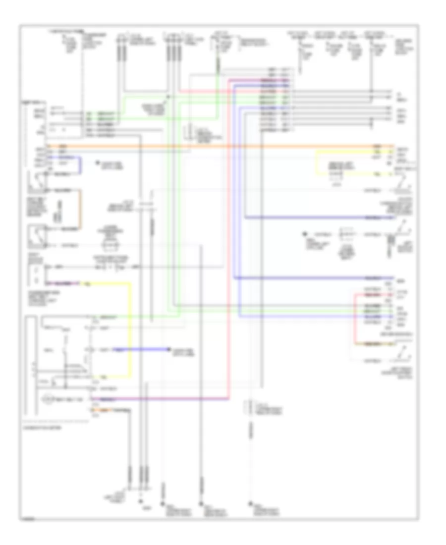
AIR CONDITIONING
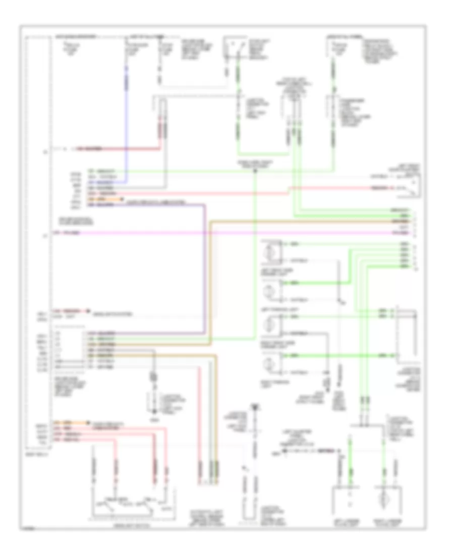
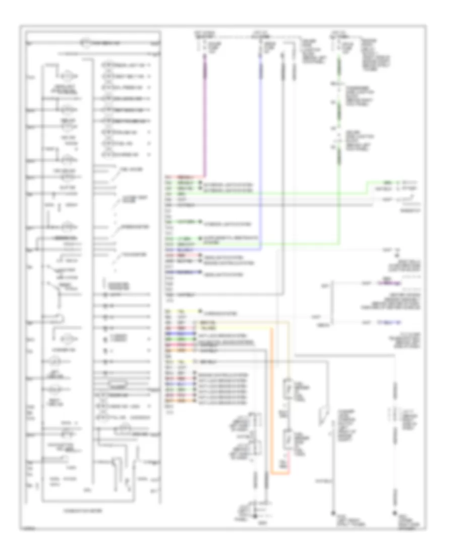
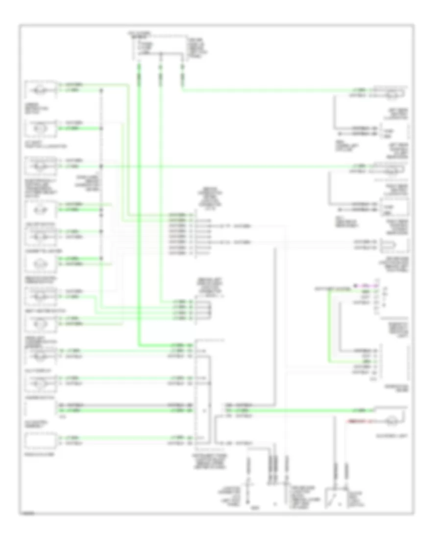
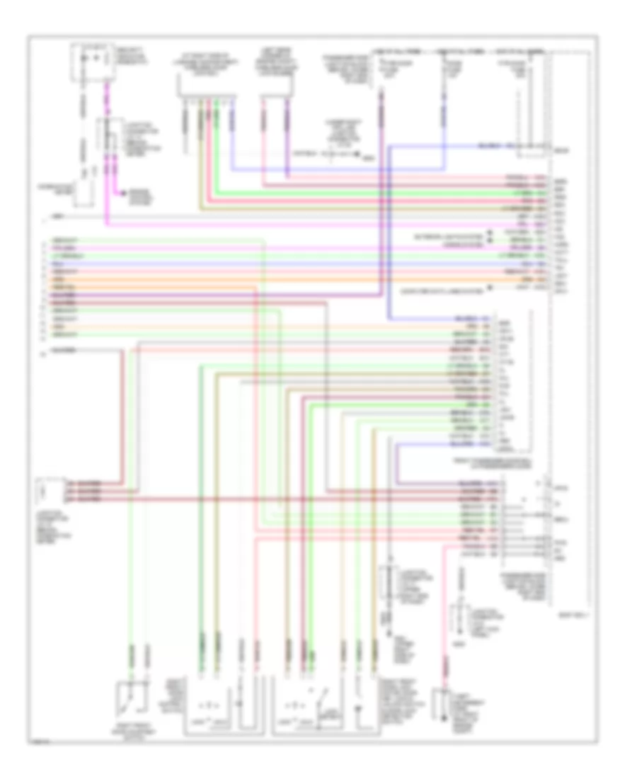
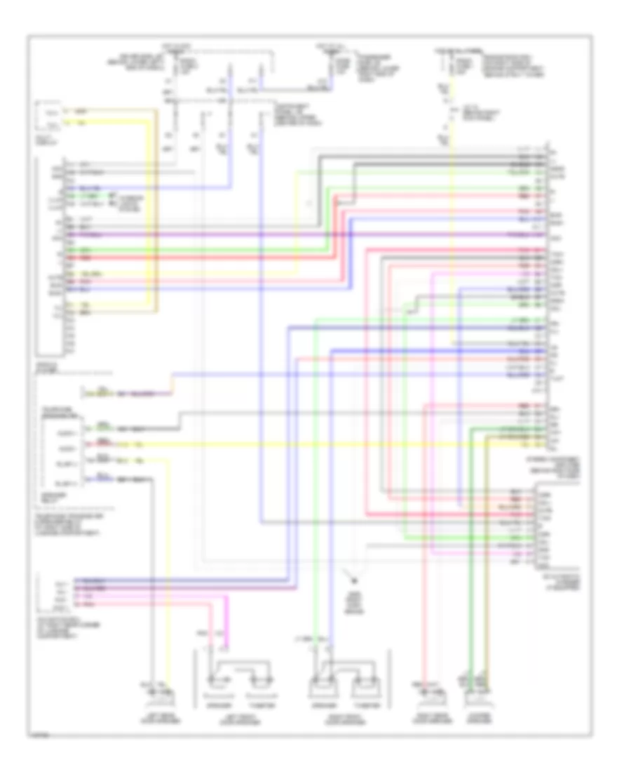
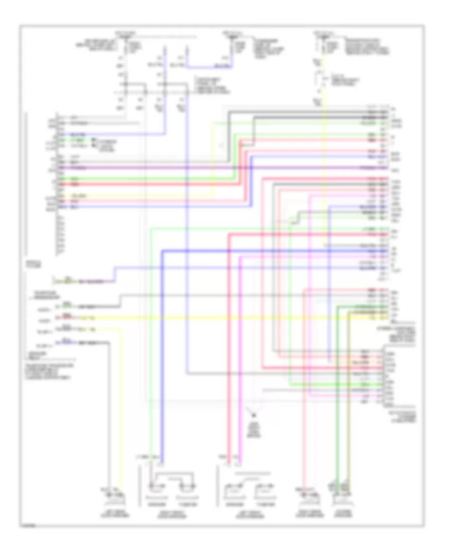
Air Conditioning Wiring Diagrams (1 of 2) for Lexus GS 400 1998
 https://portal-diagnostov.com/license.html
Automotive Electricians Portal FZCO
Automotive Electricians Portal FZCO
https://portal-diagnostov.com/license.html
https://portal-diagnostov.com/license.html
Automotive Electricians Portal FZCO
Automotive Electricians Portal FZCO
List of elements for Air Conditioning Wiring Diagrams (1 of 2) for Lexus GS 400 1998:
- (a/c sub wire harness, behind center of dash) i2
- (left fender) g102
- (right side of dash) air inlet control servo motor
- (upper right side of dash) g201
- A/c control assembly (center of dash)
- A/c dual pressure switch (left side of radiator grille)
- A/c room temperature sensor (left side of dash)
- A/c solar sensor (top right side of dash)
- A/c thermister (center of dash)
- A10
- A11
- A12
- A13
- A14
- A15
- A16
- A17
- A18
- A19
- A20
- A21
- A22
- A29
- Acc
- Acmg
- Aif
- Air
- Air mix control servo motor (driver side) (behind left side of dash, right of steering column)
- Air vent mode control servo motor (center of dash)
- Amcdr
- Amcpa
- Amhdr
- Amhpa
- Aod
- Aof
- B10
- B11
- B12
- B13
- B14
- B15
- B16
- B18
- Blw
- D10
- D13
- D21
- D27
- Dgs
- Driver side j/b (left kick panel)
- Ecu-b2 fuse 5a
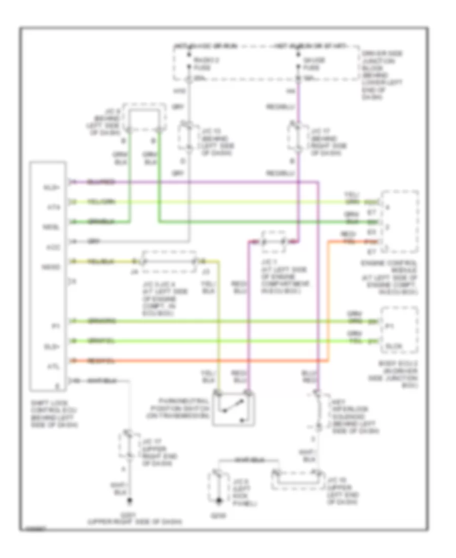
- Engine control module (left side of engine compartment, in ecu box)
- F13
- F21
- F22
- F23
- F24
- Gnd
- Gs 300
- Gs 400
- Hot at all times
- Hot in acc or on
- I2 (a/c sub wire harness, behind center of dash)
- Ill
- Instrument panel j/b (center dash reinforcement)
- Interior lights system
- J/c 17 (top right side of dash)
- J/c 18 (right kick panel)
- Lcki
- Left front corner of engine compartment) e4
- Mfrs
- Mpx+
- Mpx-
- Mpx1
- Mpx2
- Mrec
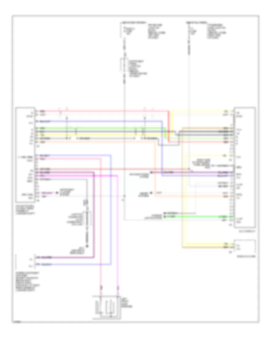
- Multi-display (w/lexus navigation system)
- Passenger side j/b (right kick panel)
- Pre
- Radio n0.2 fuse 15a
- Red
- S5-2
- S5-3
- S5-4
- Sg-1
- Sg-3
- Sg-4
- Sg-5
- Tam
- Tel in
- Telephone transceiver & speaker relay (center of rear shelf)
- Tilt & telescopic ecu (behind left side of dash)
- Tpdr
- Tpi
- Tpo
- Tppa
- Tsdr
- Tspa
- W/0 :lexus navigation system
- W/lexus navigation system
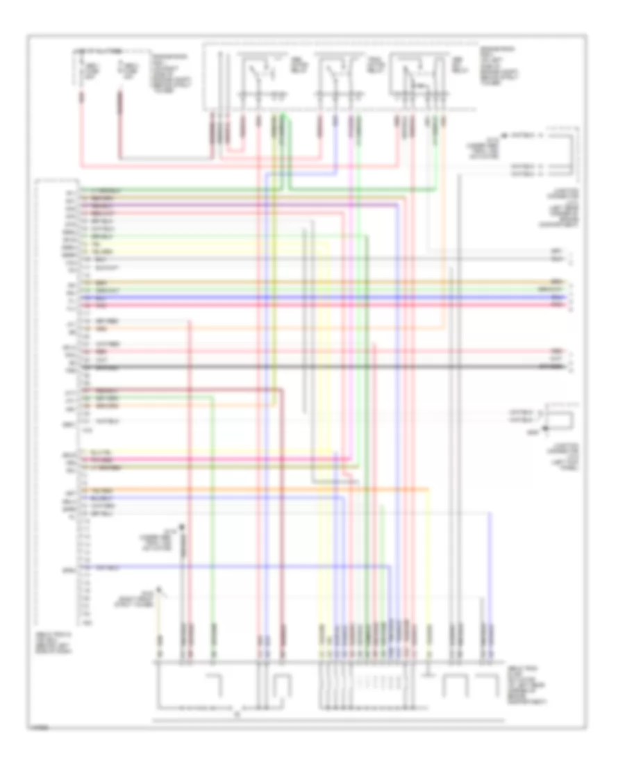
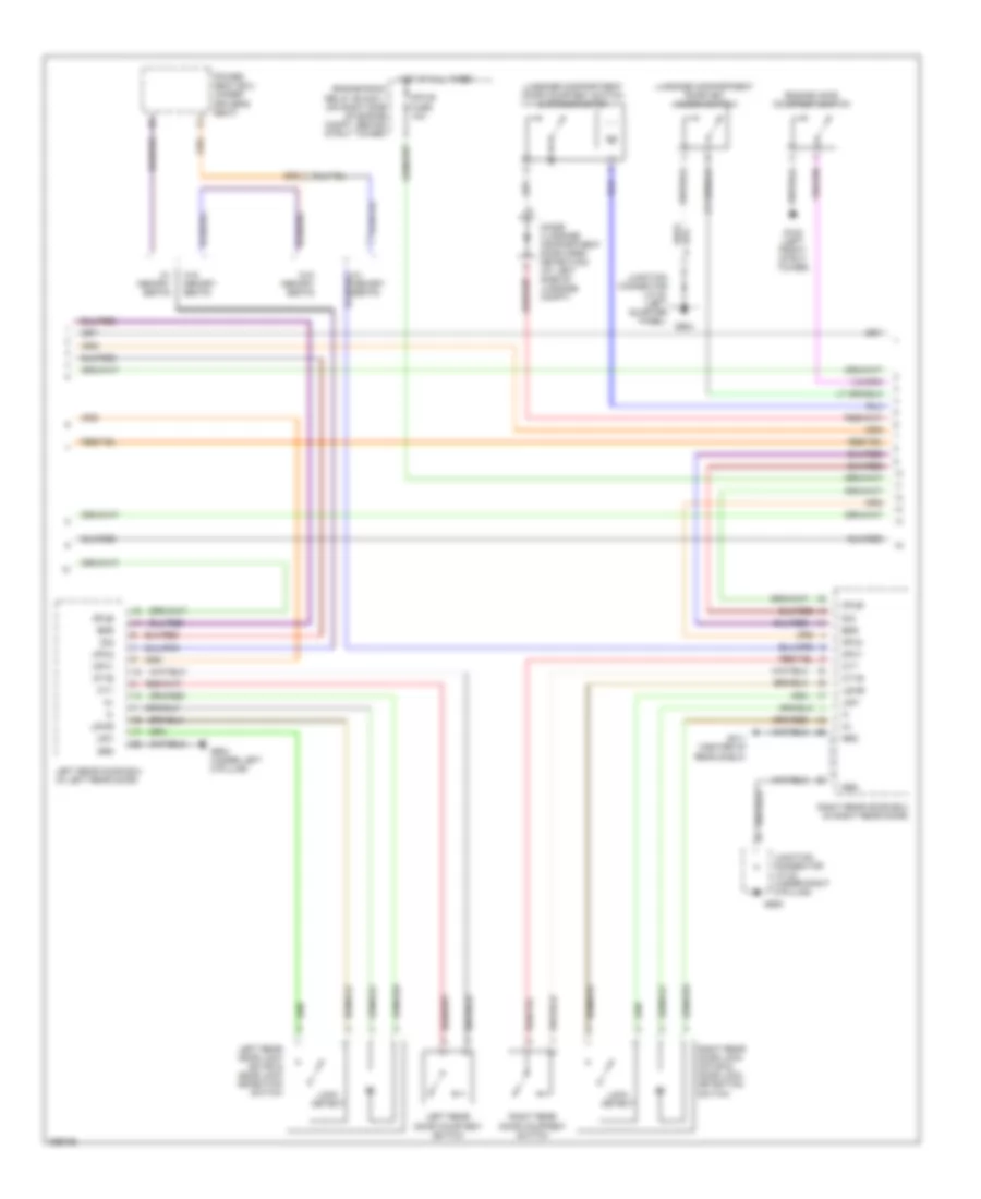
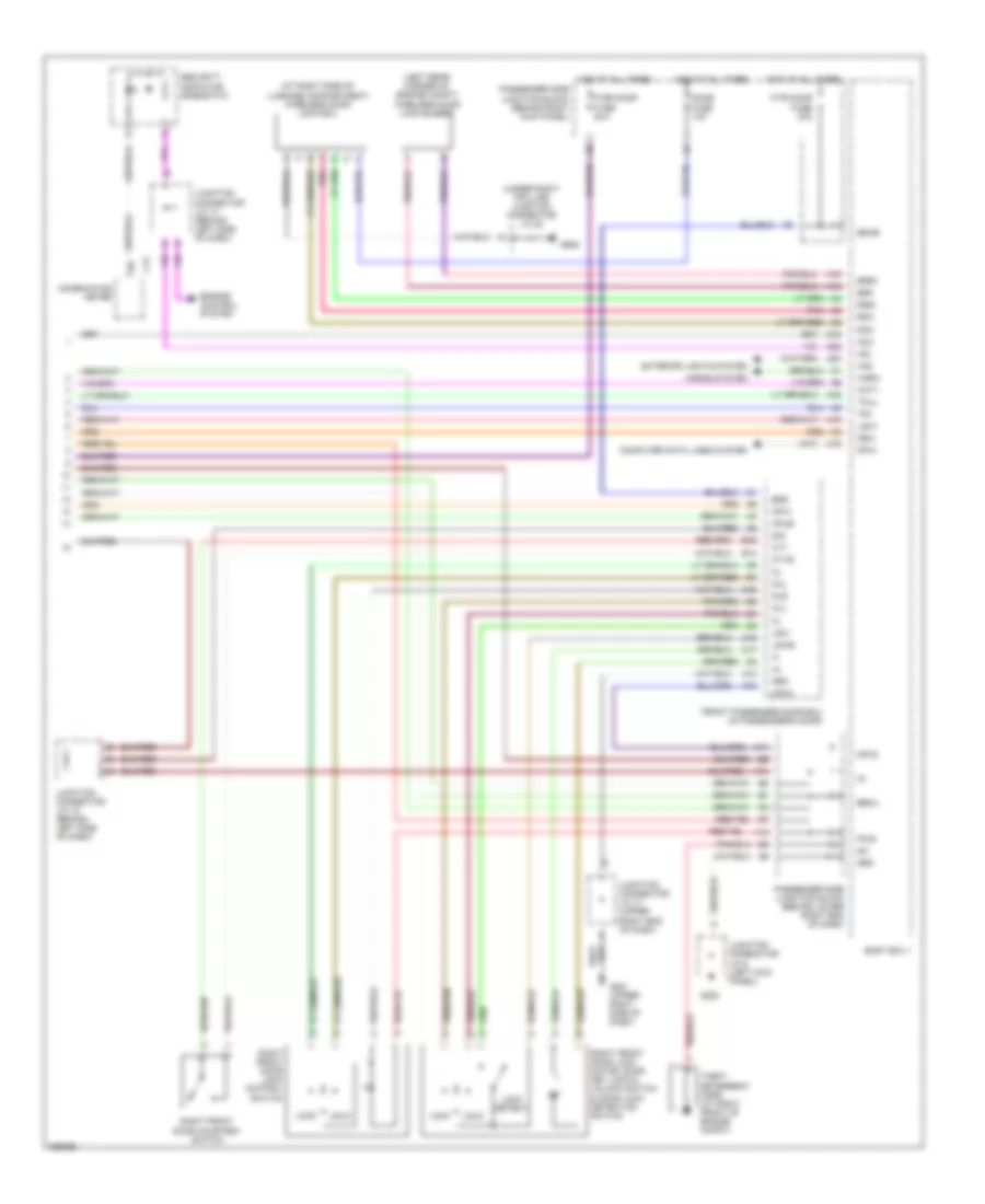
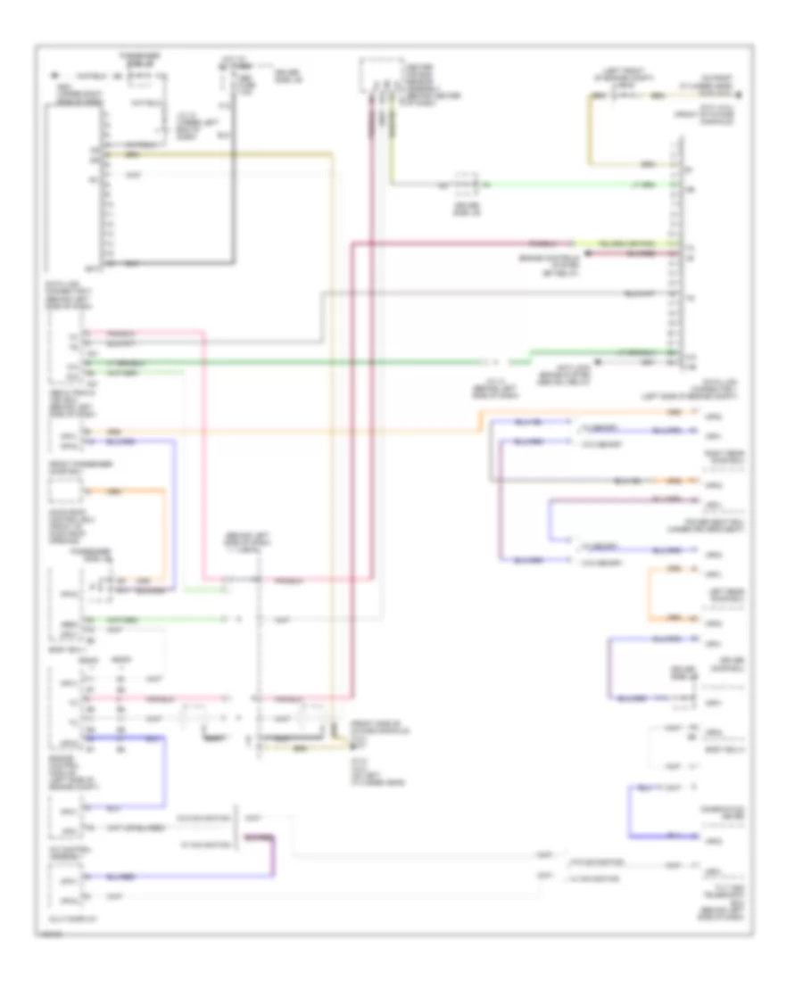
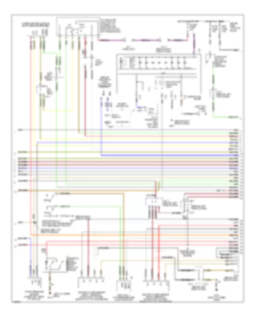
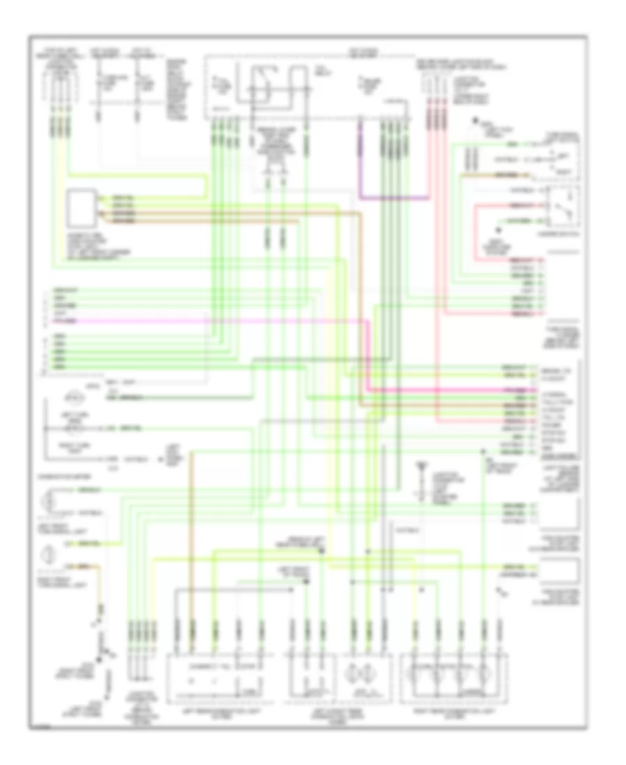
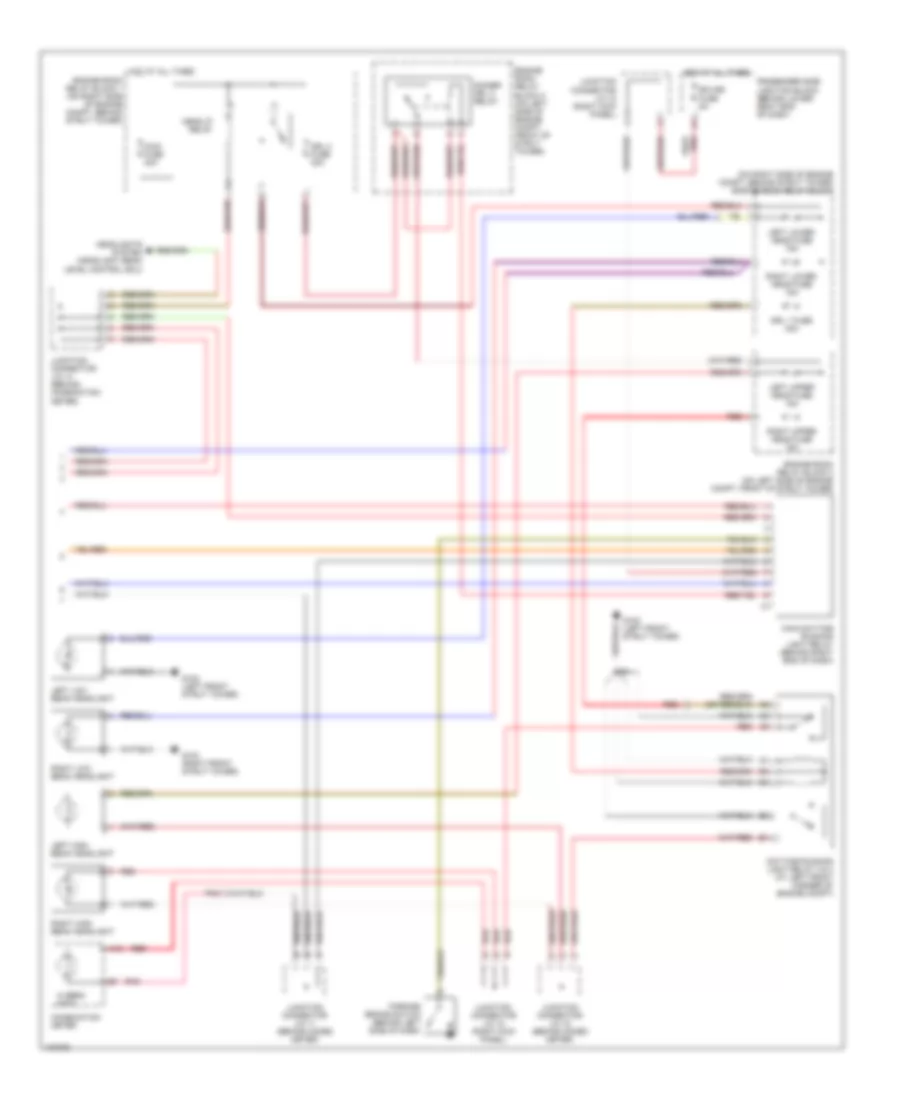
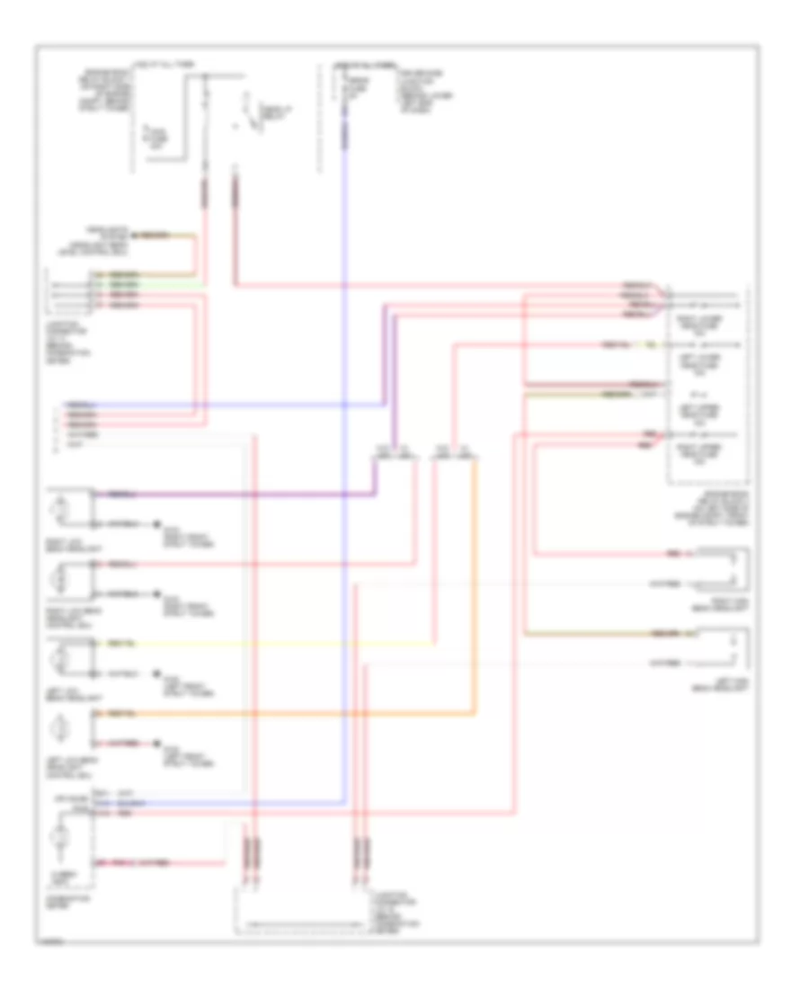
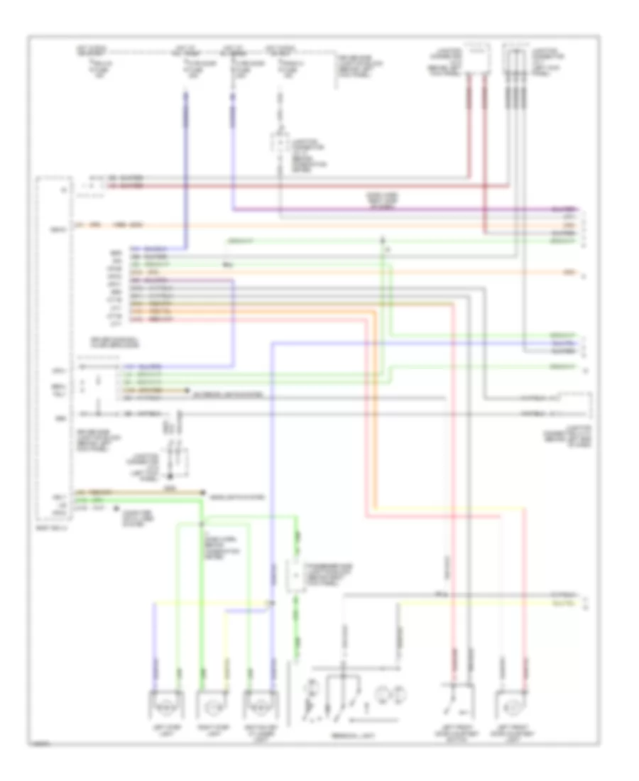
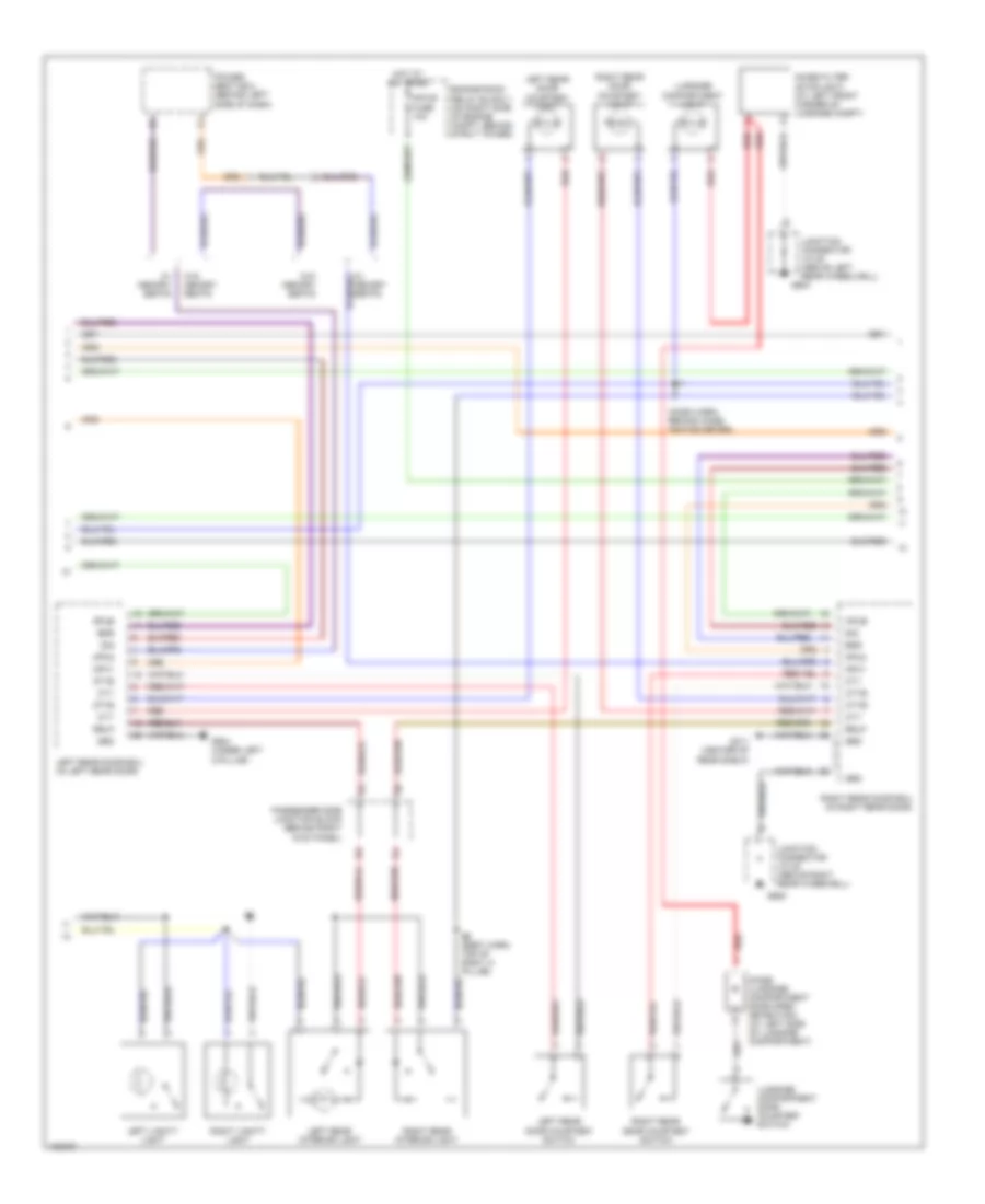
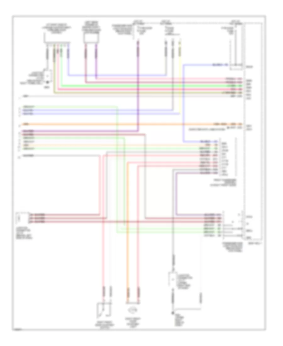
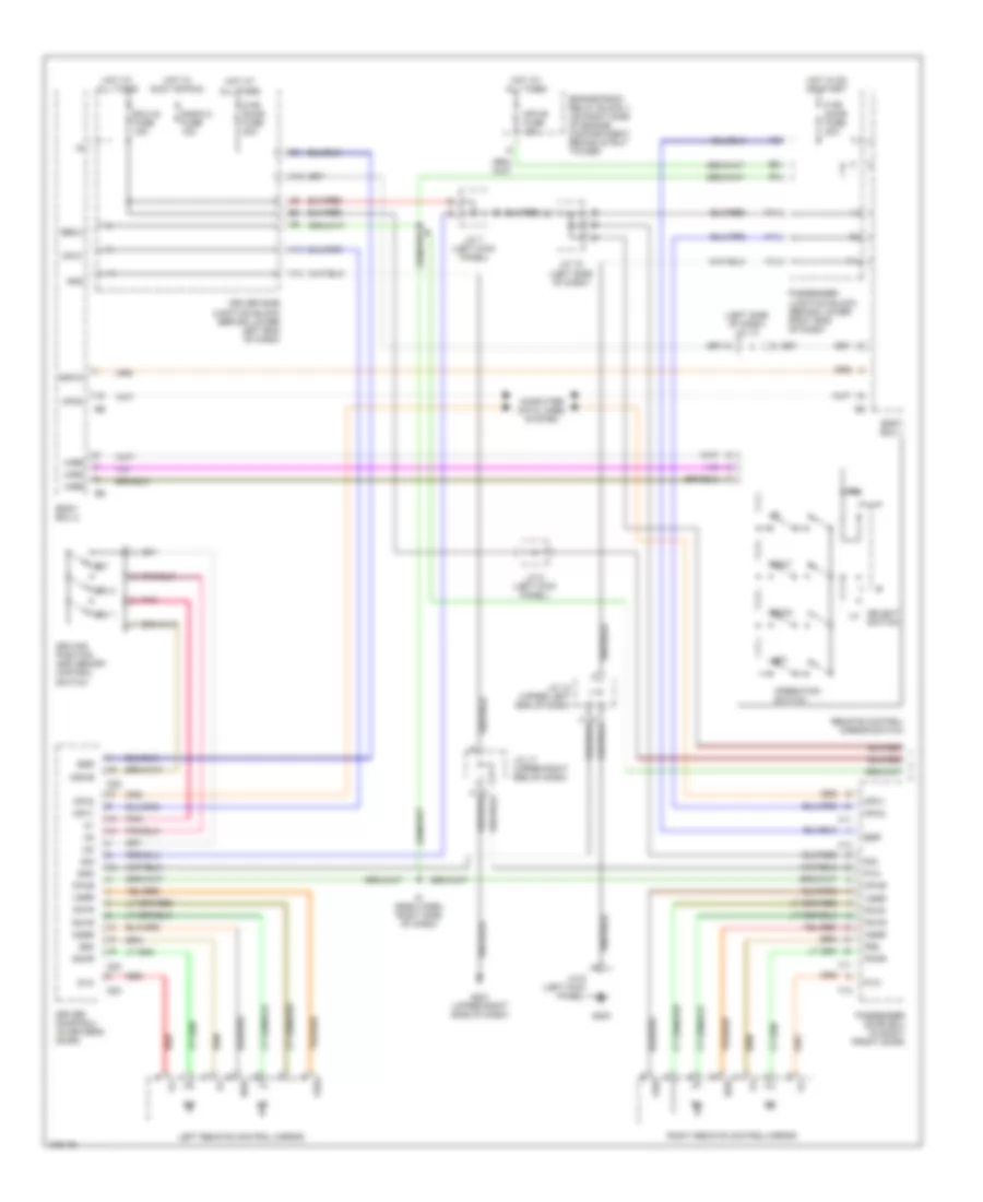
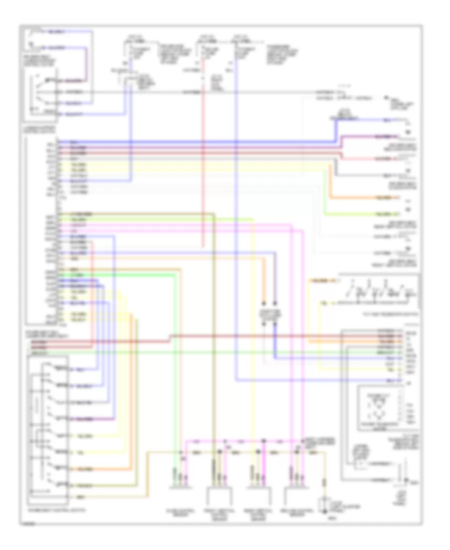
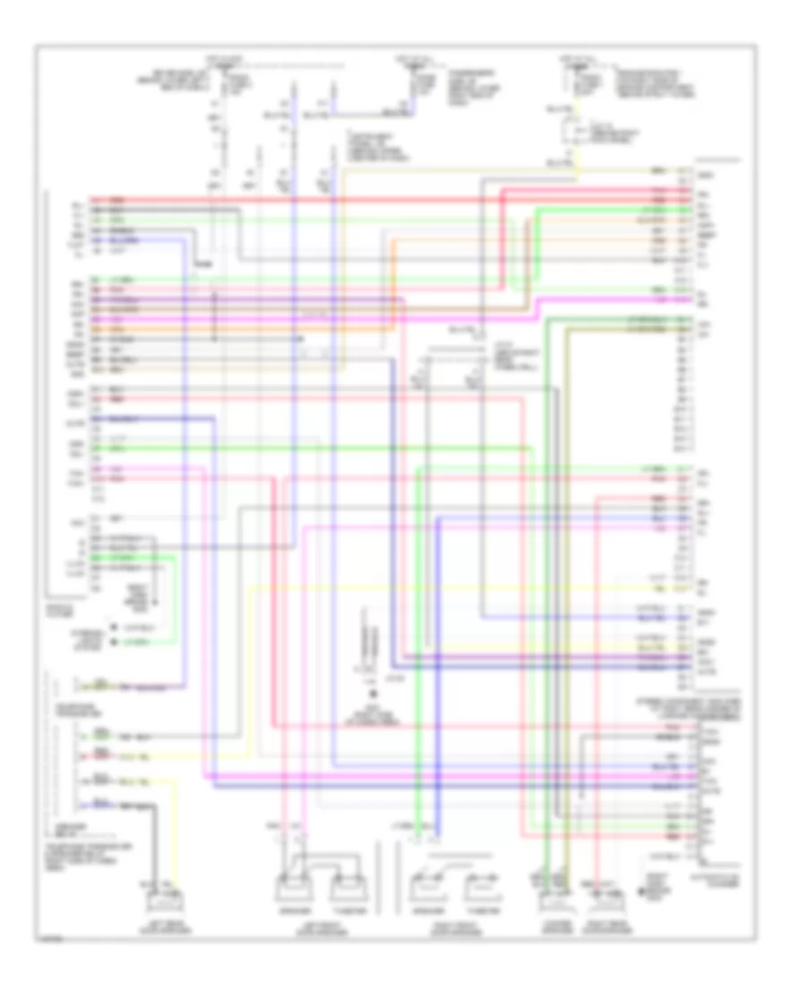
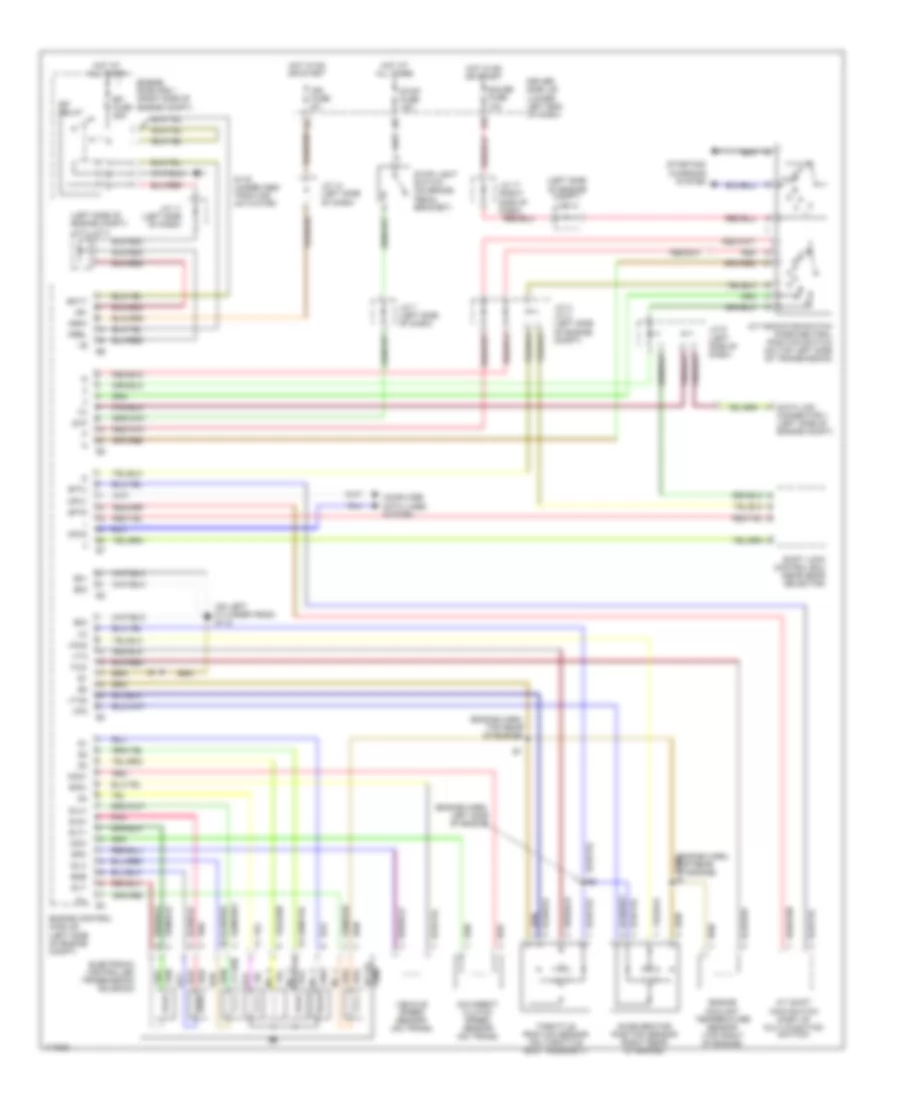
Air Conditioning Wiring Diagrams (2 of 2) for Lexus GS 400 1998
List of elements for Air Conditioning Wiring Diagrams (2 of 2) for Lexus GS 400 1998:
- (behind combination meter) g202 (canada) g102 (usa) (left fender)
- (canada) i1 (cowl wire harness, behind combination meter)
- (engine wire harness, right rear of engine) e1 (gs 400) e1 (gs 300) (engine wire harness, left front of engine)
- (left bank of cylinder head) g114 (gs 400) g131 (gs 300) (rear of intake manifold)
- (left fender) g102
- (upper right side of dash) g201
- A.c single pressure switch (left side of radiator grille)
- A/c ambient temperature sensor (left side of radiator grille)
- A/c compressor relay
- A/c condenser fan motor
- A/c magnetic clutch & lock sensor (left front of engine)
- Air mix control servo motor (front passenger side) (center of dash)
- Blower motor (right side of dash)
- Blower motor controller (center of dash)
- Body ecu 1
- Cds fan fuse 30a
- Driver side j/b (left kick panel)
- E4 (usa) (cowl wire harness, left front corner of engine compartment)
- Engine room 1 r/b (right side of engine compartment)
- Engine room 3 r/b (left side of engine compartment)
- Exhaust gas sensor (left side of radiator grille)
- F12
- Fan 1 relay
- Fan 2 relay
- Fan 3 relay
- Gas
- Gnd
- Heater fuse 10a
- Heater fuse 50a
- Hot at all times
- Hot in on or start
- Htr relay
- Ign fuse 5a
- J/c 13 (behind left side of dash)
- J/c 14 (behind left side of dash)
- J/c 17 (top right side of dash)
- J/c 2 (left side of engine compartment, in ecu box)
- Passenger j/b (right kick panel)
- Passenger side r/b (right kick panel)
- Radiator fan motor
- Rdi fan fuse 30a
- Red
- Water temperature switch (left side of radiator grille)
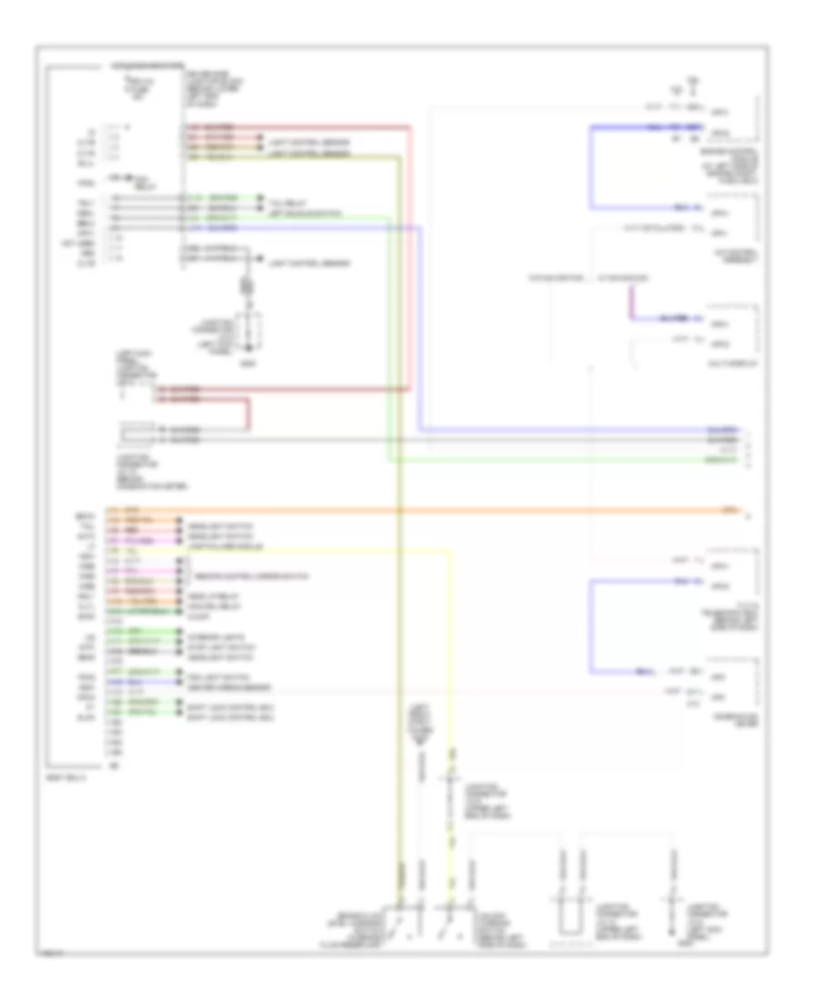
ANTI-LOCK BRAKES
Anti-lock Brake Wiring Diagrams (1 of 3) for Lexus GS 400 1998
List of elements for Anti-lock Brake Wiring Diagrams (1 of 3) for Lexus GS 400 1998:
- (under abs/ trac/ vsc actuator)
- A10
- A11
- A12
- A19
- A22
- Abs & trac & vsc actuator (at left rear corner of engine compartment)
- Abs & trac & vsc ecu (behind left side of dash)
- Abs 1 fuse 60a
- Abs 2 fuse 40a
- Abs motor relay
- Abs sol relay
- Ast
- Braided
- Engine room r/b 1 (on right side of engine compt, behind strut tower)
- Engine room r/b 2 (on left side of engine compt, behind strut tower)
- Fl+
- Fl-
- Fr+
- Fr-
- Fss
- G103 (right front strut tower)
- G116
- G116 (under abs/ trac/ vsc actuator)
- G200
- Grd1
- Grd2
- Hot at all times
- Junction connector j/c 5 (left rear corner of engine compartment)
- Junction connector j/c 6 (left kick panel)
- Mr1
- Mr2
- Mt+
- Mt-
- Mtt
- Pmc
- Pnk
- R1+
- R2+
- Red
- Sa1
- Sa2
- Sa3
- Sflh
- Sflr
- Sfrh
- Sfrr
- Srlh
- Srlr
- Srrh
- Srrr
- Str
- Trac motor relay
- Vcm
Anti-lock Brake Wiring Diagrams (2 of 3) for Lexus GS 400 1998
List of elements for Anti-lock Brake Wiring Diagrams (2 of 3) for Lexus GS 400 1998:
- (1998-99)
- (2000)
- (at left side of engine compt, behind ecu box) data link connector 1
- (behind left side of dash) data link connector 3
- (upper right end of dash) junction connector j/c 17
- A19
- Body ecu 2
- Braided
- Brake fluid level warning switch (in brake fluid reservoir)
- C (or b)
- Driver side j/b (behind left kick panel)
- Driver side j/c (behind left kick panel)
- Ecu-ig fuse 15a
- G102 (usa) (left front strut tower)
- G200
- G201 (upper right side of dash)
- G202
- Hot at all times
- Hot in run or start
- Junction connector j/c 1 (under ecu box)
- Junction connector j/c 10 (upper left end of dash)
- Junction connector j/c 15 (behind combination meter)
- Junction connector j/c 3, j/c 4 (under ecu box)
- Junction connector j/c 6 (left kick panel)
- Junction connector j/c 7 (left kick panel)
- Junction connector j/c 9 (upper left end of dash)
- Left front abs speed sensor (left front wheel assembly)
- Master cylinder pressure sensor (at left rear corner of engine compartment)
- Park/neutral position switch (on transmission)
- Pnk
- Red
- Right front abs speed sensor (right front wheel assembly)
- Steering sensor (combination switch)
- Stop fuse 15a
- Stoplight switch (on brake pedal bracket)
- Vsc off switch
- Vsc warning buzzer (behind left side of dash)
Anti-lock Brake Wiring Diagrams (3 of 3) for Lexus GS 400 1998
List of elements for Anti-lock Brake Wiring Diagrams (3 of 3) for Lexus GS 400 1998:
- (3.0l)
- (4.0l)
- (upper left end of dash) junction connector j/c 9
- (upper right end of dash) junction connector j/c 17
- A20
- A21
- Abs & trac & vsc ecu (behind left side of dash)
- Abs deceleration sensor (under rear of center console)
- Abs indic
- B11
- B13
- B14
- B15
- B16
- B17
- Braided
- Brake indic
- Brl
- Combination meter
- Csw
- D/g
- Driver side j/b (bhind left kick panel)
- Eng+
- Eng-
- Engine control module (at left side of engine compt, in ecu box)
- Flo
- Gauge fuse 10a
- Ggrd
- Gl1
- Gl2
- Grd3
- Grd4
- Gss
- Gyaw
- Headlights system
- Hot in start or run
- Ig1
- Ig2
- Ign fuse 5a
- Ind
- Junction connector j/c 14 (behind comb- ination meter)
- Left rear abs speed sensor (left rear wheel assembly)
- Neo
- Pnk
- Red
- Right rear abs speed sensor (right rear wheel assembly)
- Rl+
- Rl-
- Rr+
- Rr-
- Slip indic
- Sp1
- Ss1+
- Ss1-
- Stp
- Trc+
- Trc-
- Vgs
- Vsc indic
- Vsc off indic
- Vscw
- Vys
- Yaw
- Yaw rate sensor (under rear of center console)
- Yss
ANTI-THEFT
Anti-theft Wiring Diagram (1 of 3) for Lexus GS 400 1998
List of elements for Anti-theft Wiring Diagram (1 of 3) for Lexus GS 400 1998:
- (dash harn, right side of dash)
- A13
- A15
- A17
- A19
- B14
- B15
- Bdr
- Becu
- Body ecu 2
- C12
- C18
- Computer data lines system
- Cpub
- Cty
- Ctye
- D fr door fuse 20a
- D rr door fuse 20a
- Driver door ecu (in driver's door)
- Driver side junction block (behind left kick panel)
- Ecu-ig fuse 15a
- Exterior lights system
- G200
- Grd
- Gswo
- H10
- H11
- H13
- Headlights system
- Hot at all times
- Hot in accy or run
- Hot in run or start
- Hrly
- Ile
- Interior lights system
- Junction connector j/c 10 (behind left side of dash)
- Junction connector j/c 13 (behind left side of dash)
- Junction connector j/c 6 (left kick panel)
- Junction connector j/c 7 (left kick panel)
- Junction connector j/c 8 (behind left kick panel)
- Kul
- Left door lock control switch (power window master switch)
- Left front door courtesy switch
- Left front door lock motor, door key lock & unlock switch & door lock detection switch
- Lock
- Lock detect
- Lsw
- Lswe
- Mpx1
- Mpx2
- Mul
- Pwe
- Radio 2 fuse 15a
- Sig
- Trly
- Unlk
Anti-theft Wiring Diagram (2 of 3) for Lexus GS 400 1998
List of elements for Anti-theft Wiring Diagram (2 of 3) for Lexus GS 400 1998:
- Bdr
- Cpub
- Cty
- Ctye
- Diode (luggage compartment door open detection) (at left side of luggage compt)
- Engine hood courtesy switch
- Engine room relay block 1 (on right side of engine compt, behind strut tower)
- G102 (left front strut tower)
- G311 (center of rear shelf)
- G904
- G904 (under left c-pillar)
- G905
- Grd
- Hot at all times
- Junction connector j/c 20 (left quarter panel)
- Junction connector j/c 22 (under right c-pillar)
- Left rear door courtesy switch
- Left rear door ecu (in left rear door)
- Left rear door lock motor & door lock detection switch
- Lock detect
- Lsw
- Lswe
- Luggage compartment door courtesy switch & opener motor
- Luggage compartment door key unlock switch
- Mpx-b fuse 10a
- Mpx1
- Mpx2
- Power seat ecu (under driver's seat)
- Right rear door courtesy switch
- Right rear door ecu (in right rear door)
- Right rear door lock motor & door lock detection switch
- Sig
- W/ memory seats
- W/o memory seats
Anti-theft Wiring Diagram (3 of 3) for Lexus GS 400 1998
List of elements for Anti-theft Wiring Diagram (3 of 3) for Lexus GS 400 1998:
- (at right side of luggage compartment) wireless door lock ecu
- (left rear corner of engine compt) wireless door lock buzzer
- (under right c-pillar) junction connector j/c 22
- A10
- A12
- A13
- A15
- A16
- A18
- A19
- A22
- A25
- Acc
- B14
- B15
- Bdr
- Becu
- Body ecu 1
- Bsub
- Bzr
- Bzr2
- C12
- C15
- C16
- C17
- Combination meter
- Computer data lines system
- Cpub
- Cty
- Ctye
- Dle
- Dome fuse 10a
- Engine control system
- Exterior lights system
- F11
- Front passenger door ecu (in passenger's door)
- G200
- G201 (upper right side of dash)
- G905
- Grd
- Gsw
- H11
- H13
- Haz
- Hcty
- Horn
- Horns system
- Hot at all times
- Ind
- Junction conenctor j/c 6 (left kick panel)
- Junction connector j/c 14 (behind left side of dash)
- Junction connector j/c 15 (behind left side of dash)
- Junction connector j/c 17 (upper right end of dash)
- Kul
- Lgcy
- Lock
- Lock detect
- Lsw
- Lswe
- Mpx1
- Mpx2
- Mul
- P fr door fuse 20a
- P rr door fuse 20a
- Passenger side junction block (behind lower right end of dash)
- Passenger side junction block (behind right kick panel)
- Pnk
- Pws
- Rco
- Rda
- Right front door courtesy switch
- Right front door lock control switch
- Right front door lock motor, door key lock & unlock switch & door lock detection switch
- Rssi
- Security indicator (rheostat)
- Sig
- Theft deterrent horn (at right front of engine compt)
- Tkul
- Tr+
- Unlk
BODY COMPUTER
Body Computer Wiring Diagrams (1 of 2) for Lexus GS 400 1998
List of elements for Body Computer Wiring Diagrams (1 of 2) for Lexus GS 400 1998:
- (left front strut tower) g102
- (left kick panel) junction connector j/c 7
- 3.0l
- 4.0l
- A/c control assembly
- A10
- A11
- A12
- A13
- A14
- A15
- A16
- A17
- A18
- A19
- A20
- A21
- A22
- A23
- A24
- A25
- Acan
- Altl
- Auto
- B11
- Becu
- Blvl
- Body ecu 2
- Brake fluid level warning switch (in brake fluid reservoir)
- C13
- Center airbag sensor
- Clock
- Cltb
- Clte
- Clts
- Combination meter
- D27
- D28
- Dbkl
- Driver side junction block (behind lower left end of dash)
- Ecu-ig fuse 15a
- Engine control module (at left side of engine compt, in ecu box)
- F11
- F24
- Ffgo
- Ffog
- Fog light switch
- Fog relay
- G200
- Grd
- Gsw
- Gswo
- H11
- H13
- Head
- Head lp relay
- Headlight switch
- Hot in run or start
- Hrly
- Ile
- Interior lights
- Junction connector j/c 10 (upper left end of dash)
- Junction connector j/c 15 (behind combination meter)
- Junction connector j/c 6 (left kick panel)
- Junction connector j/c 9 (upper left end of dash)
- Ksw
- Lamp failure module
- Left buckle switch
- Light control sensor
- Main drl relay
- Mirb
- Mire
- Mirs
- Mpx
- Mpx+
- Mpx-
- Mpx1
- Mpx2
- Multi-display
- Not used
- Red
- Remote control mirror switch
- Shift lock control ecu
- Slck
- Stop light switch
- Stpi
- Tail
- Tail relay
- Tilt & telescopic ecu (behind left side of dash)
- Trly
- Unlock warning switch (behind left side of dash)
- W/ navigation
- W/o navigation
Body Computer Wiring Diagrams (2 of 2) for Lexus GS 400 1998
List of elements for Body Computer Wiring Diagrams (2 of 2) for Lexus GS 400 1998:
- A10
- A11
- A12
- A13
- A14
- A15
- A16
- A17
- A18
- A19
- A20
- A21
- A22
- A23
- A24
- A25
- Acc
- Anti-theft indicator
- B10
- B11
- Becu
- Body ecu 1
- Bsub
- Bzr
- Bzr2
- C18
- D24
- Data link connector 3
- Dfg
- Driver door ecu (in driver's door)
- Driver side junction block (behind lower left end of dash)
- Engine hood courtesy switch
- Engine room relay block 1 (on right side of engine compt, behind strut tower)
- F11
- F12
- Front passenger door ecu (in passenger's door)
- G201 (upper right side of dash)
- Grd
- Gsw
- H10
- H11
- H13
- Haz
- Hazard switch
- Hcty
- Heater relay
- Horn
- Horn relay
- Hot at all times
- Hot in acc or run
- Ind
- Junction connector j/c 13 (behind combination meter)
- Left rear door ecu (in left rear door)
- Lgcy
- Luggage compartment courtesy switch
- Luggage compartment key unlock switch
- Luggage compartment opener motor
- Luggage compartment opener switch
- Mir relay
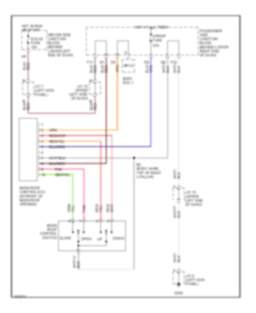
- Moon roof control ecu
- Mpx-b fuse 10a
- Mpx1
- Mpx2
- Not used
- Obd2
- P fr door fuse 20a
- P19
- Parking brake switch (behind left side of dash)
- Passenger side junction block (behind lower right end of dash)
- Pbkl
- Pkb
- Pnk
- Power seat ecu (under driver's seat)
- Power window master switch
- Pwr
- Pws
- R12
- R13
- Radio 2 fuse 15a
- Rco
- Rda
- Right front door lock switch
- Right rear door ecu (in right rear door)
- Right seat occupant sensor
- Rssi
- Snow
- Theft deterrent horn
- Tkul
- Tr+
- Transmission pattern select switch
- Tsw
- W/ memory seat
- W/o memory seat
- Wireless door lock buzzer
- Wireless door lock ecu
COMPUTER DATA LINES
Computer Data Lines for Lexus GS 400 1998
List of elements for Computer Data Lines for Lexus GS 400 1998:
- (behind left side of dash) j/c 9
- (front side of intake manifold) (3.0l) g131
- (left front of engine compt) j/c 2
- (on right cylinder head) g120 (4.0l)
- A/c control assembly
- A21
- Abs & trac & vsc ecu (behind left side of dash)
- Anti-lock brake system (abs sol relay)
- Bat
- Body ecu 1
- Body ecu 2
- Center air bag sensor assembly (behind center of dash)
- Combination meter
- D/g
- Data link connector 1 (left side of engine compt)
- Data link connector 3 (behind left side of dash)
- Driver door ecu
- Driver side j/b
- Engine control module (left side of engine compt)
- Engine controls system (efi relay)
- F13
- Front passenger door ecu
- G112 (4.0l) (on left cylinder head)
- G131 (3.0l) (front of intake manifold)
- G201 (upper right side of dash)
- Gs300
- Gs400
- H11
- H12
- Hot at all times
- J/c 10 (upeer left end of dash)
- J/c 14 (behind left side of dash)
- Left rear door ecu
- Moon roof control ecu (front of moon roof opening)
- Mpx+
- Mpx-
- Mpx1
- Mpx2
- Multi-display
- Nca
- Obd fuse 7.5a
- Obd2
- Passenger side j/b
- Power seat ecu (under driver's seat)
- Right rear door ecu
- Sil
- Tilt and telescopic ecu (behind left side of dash)
- W/ memory
- W/ navigation
- W/o memory
- W/o navigation
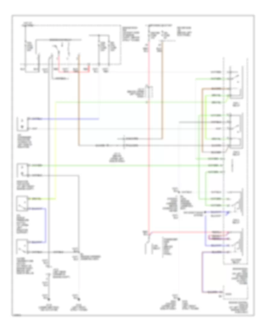
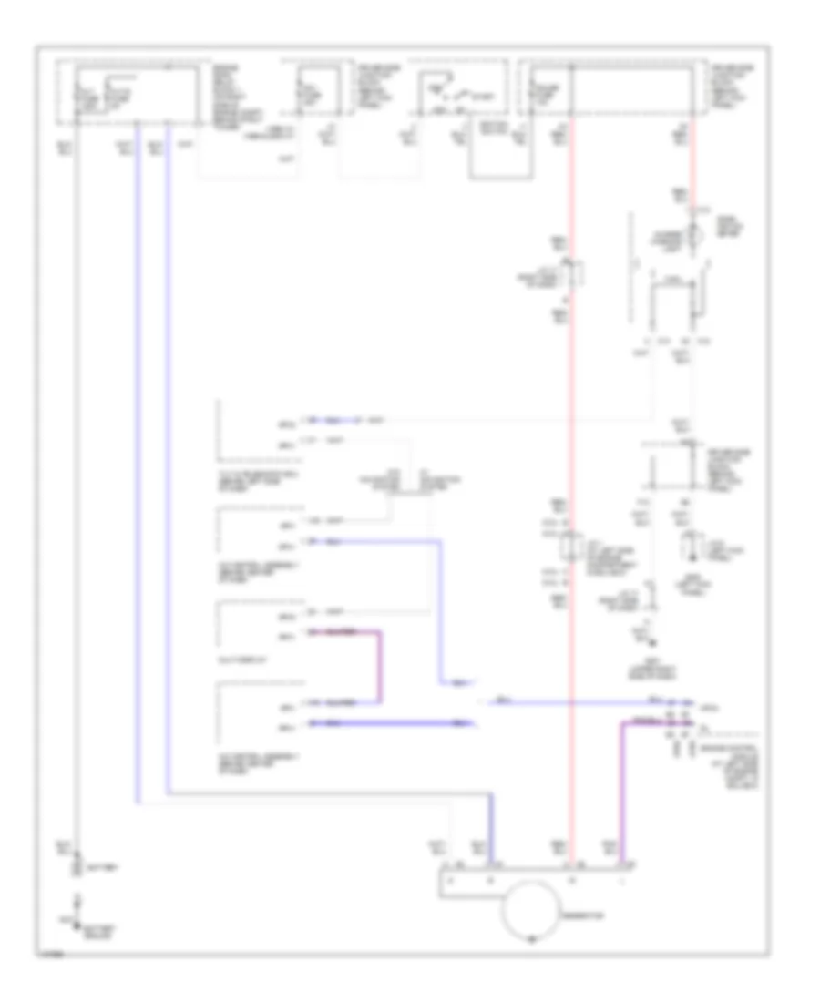
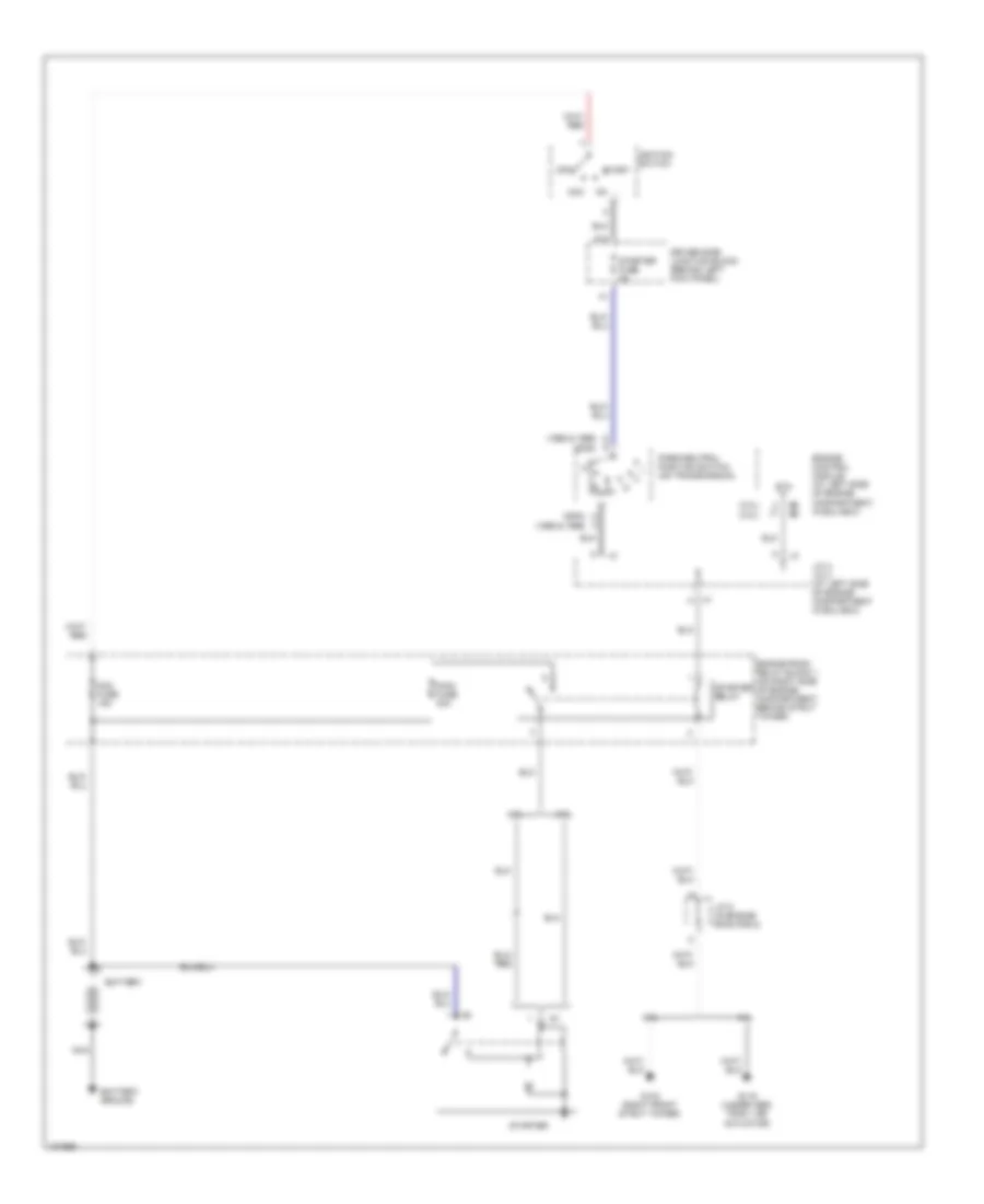
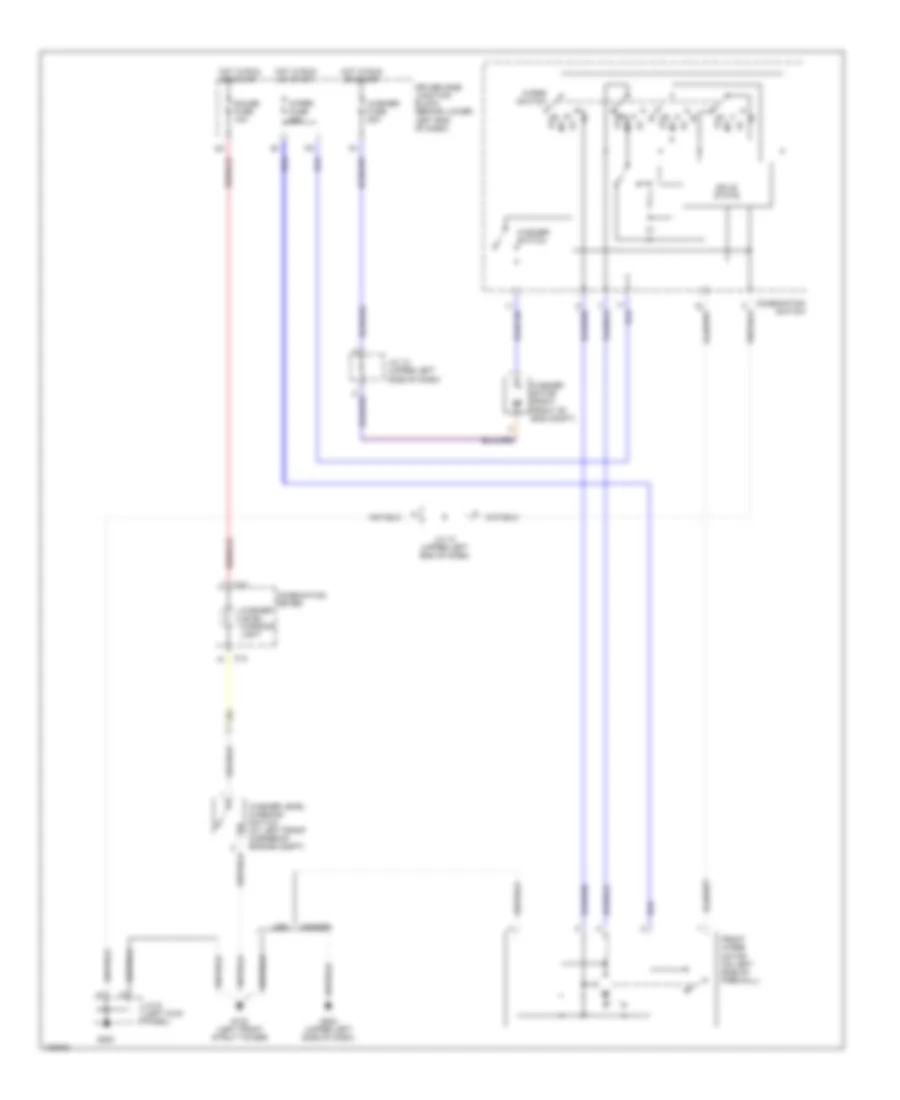
COOLING FAN
Cooling Fan Wiring Diagram for Lexus GS 400 1998
List of elements for Cooling Fan Wiring Diagram for Lexus GS 400 1998:
- A/c comp relay
- A/c condenser fan motor (in front of left side of radiator)
- A/c single pressure switch (at upper left radiator support)
- Acmg
- Air conditioning system
- Cds fan fuse 30a
- Driver side j/b (behind left kick panel)
- E4 (usa) (engine harness, under ecu box)
- Engine control module (at left side of engine compt, in ecu box)
- Engine main relay
- Engine room r/b (on right side of engine compt, behind strut tower)
- Engine room r/b 3 (on left side of engine compt, front of strut tower)
- Fan 1 relay
- Fan 2 relay
- Fan 3 relay
- Fan main fuse 50a
- G102 (left front strut tower)
- G102 (usa) (left front strut tower)
- G116 (under abs/trac/ vsc actuator)
- G202 (canada) (upper left side of dash)
- Heater fuse 10a
- Hot at all times
- Hot in run or start
- Htr relay
- I1 (canada) (dash harness, behind combination meter)
- Ign fuse 5a
- J/c 13 (behind upper left side of dash)
- J/c 14 (behind upper left side of dash)
- J/c 5 (left rear corner of engine compt)
- Passenger side j/b (behind right kick panel)
- Radiator fan motor (at left front engine compt)
- Rdi fan fuse 30a
- Red
- Under ecu box)
- Water temperature switch (at front of engine compt, behind left side of grille)
CRUISE CONTROL
Cruise Control Wiring Diagram for Lexus GS 400 1998
List of elements for Cruise Control Wiring Diagram for Lexus GS 400 1998:
- (behind ecu box)
- (engine harn, left side of engine)
- (engine harn, top left side of engine)
- (in ecu box)
- (left cylinder head)
- (left kick panel) j/6 c
- (right cylinder head)
- +b1
- +bm
- A/t indicator light switch
- Accel position sensor (top center of engine)
- Batt
- Braided
- C12
- C13
- Cancel
- Ccs
- Cl+
- Cl-
- Combination meter
- Computer data lines system
- Conn e2
- Conn e3
- Conn e4
- Conn e5
- Conn e6
- Conn e7
- Cpu
- Cruise control switch
- Cruise ind
- Data link connector 1
- Driver side j/b
- Driver side junction block
- E01
- E02
- E03
- Efi fuse 25a
- Efi relay
- Engine control module (left side of engine compt, in ecu box)
- Engine room relay block 1
- Eom
- Etcs fuse 15a
- G102 (left front strut tower)
- G104 (left rear corner of engine compt)
- G112
- G112 (left cylinder head)
- G120
- G200
- Gauge fuse 10a
- Ge01
- Hot at all times
- Hot in on or start
- Ign fuse 5a
- Igsw
- J/c 1 (in ecu box)
- J/c 11 (left side of dash)
- J/c 14 (behind left side of dash)
- J/c 17 (behind right side of dash)
- J/c 2 (in ecu box)
- J/c 3
- J/c 3 (in ecu box)
- J/c 5 (in engine room relay block 2)
- J/c 7 (behind left kick panel)
- J/c 9 (behind left side of dash)
- J/c4
- Main
- Me01
- Mpx2
- Mrel
- Pnk
- Red
- Res/ acc
- Set/ coast
- Sti-
- Stop fuse 15a
- Stoplight switch (on brake pedal bracket)
- Stp
- Throttle control motor (on throttle body)
- Throttle position sensor (on throttle body)
- Vpa
- Vpa2
- Vta
- Vta2
DEFOGGERS
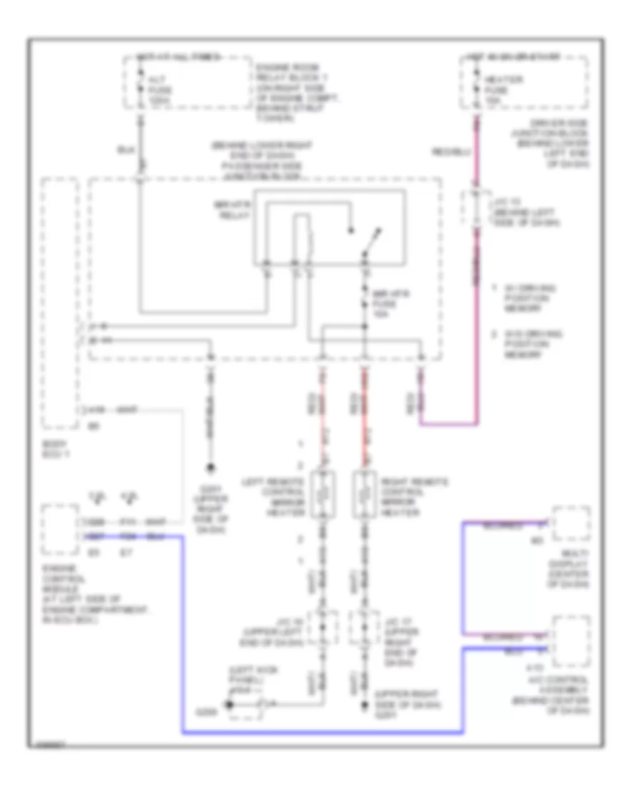
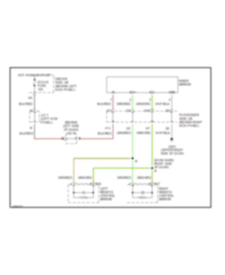
Heated Mirrors Wiring Diagram for Lexus GS 400 1998
List of elements for Heated Mirrors Wiring Diagram for Lexus GS 400 1998:
- (behind lower right end of dash) passenger side junction block
- (left kick panel) j/c 6
- (upper right side of dash) g201
- 3.0l
- 4.0l
- A/c control assembly (behind center of dash)
- A12
- A13
- A19
- Alt fuse 120a
- Body ecu 1
- D27
- D28
- Driver side junction block (behind lower left end of dash)
- Engine control module (at left side of engine compartment, in ecu box)
- Engine room relay block 1 (on right side of engine compt, behind strut tower)
- F11
- F24
- G200
- G201 (upper right side of dash)
- H10
- Heater fuse 10a
- Hot at all times
- Hot in on or start
- J/c 10 (upper left end of dash)
- J/c 13 (behind left side of dash)
- J/c 17 (upper right end of dash)
- Left remote control mirror heater
- Mir htr fuse 10a
- Mir htr relay
- Multi display (center of dash)
- Right remote control mirror heater
- W/ driving position memory
- W/o driving position memory
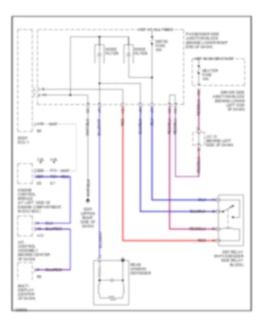
Rear Defogger Wiring Diagram for Lexus GS 400 1998
List of elements for Rear Defogger Wiring Diagram for Lexus GS 400 1998:
- 3.0l
- 4.0l
- A/c control assembly (behind center of dash)
- A13
- A19
- Body ecu 1
- D27
- D28
- Def relay (in passenger side relay block)
- Defog fuse 30a
- Driver side junction block (behind lower left end of dash)
- Engine control module (at left side of engine compartment, in ecu box)
- F11
- F24
- G201 (upper right side of dash)
- Heater fuse 10a
- Hot at all times
- Hot in on or start
- J/c 13 (behind left side of dash)
- Multi display (center of dash)
- Noise filter
- Passenger side junction block (behind lower right end of dash)
- Rear window defogger
- Red
ELECTRONIC POWER STEERING
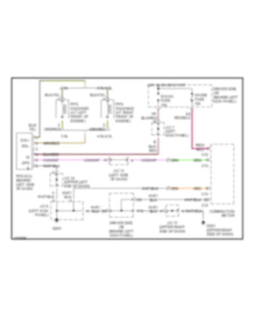
Electronic Power Steering Wiring Diagram for Lexus GS 400 1998
List of elements for Electronic Power Steering Wiring Diagram for Lexus GS 400 1998:
- 3.0l
- 4.0l/4.3l
- C12
- C13
- Combination meter
- Driver side j/b (behind left kick panel)
- Ecu-ig fuse 15a
- F13
- G200
- G201 (upper right side of dash)
- Gauge fuse 10a
- Hot in on or start
- J/c 10 (upper left end of dash)
- J/c 13 (left side of dash)
- J/c 17 (upper right end of dash)
- J/c 6 (left kick panel)
- J/c 7 (left kick panel)
- Pps ecu (behind left side of dash)
- Pps solenoid (at left front of engine)
- Pps solenoid (at right front of engine)
- Sol+
- Sol-
- Spd
ENGINE PERFORMANCE
4.0L
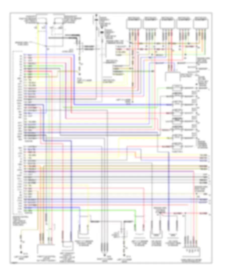
4.0L, Engine Performance Wiring Diagrams (1 of 4) for Lexus GS 400 1998
List of elements for 4.0L, Engine Performance Wiring Diagrams (1 of 4) for Lexus GS 400 1998:
- (engine harn, in ecu box)
- (engine harn, left side of engine)
- (engine harn, right side of engine)
- (engine harn, top rear of engine)
- (left cylinder head)
- (left cylinder head) g112
- (right cylinder head)
- A braided
- Acis
- Braided
- Camshaft position sensor (left front of engine)
- Cl-
- Conn e2
- Conn e3
- Crankshaft position sensor (left front of engine)
- E01
- E02
- E03
- E1 (engine harness, top rear of engine)
- E2g
- Engine control module (left side of engine compt, in ecu box)
- Evg
- G112
- G112 (left cylinder head)
- G120
- Ge01
- Htl
- Htr
- Igf1
- Igf2
- Ignition coil & igniter 1
- Ignition coil & igniter 2
- Ignition coil & igniter 3
- Ignition coil & igniter 4
- Ignition coil & igniter 5
- Ignition coil & igniter 6
- Ignition coil & igniter 7
- Ignition coil & igniter 8
- Igt1
- Igt2
- Igt3
- Igt4
- Igt5
- Igt6
- Igt7
- Igt8
- Injector 1
- Injector 2
- Injector 3
- Injector 4
- Injector 5
- Injector 6
- Injector 7
- Injector 8
- J/c 2 (in ecu box)
- Knkl
- Knkr
- Knock sensor 1 (top center of engine)
- Knock sensor 2 (top center of engine)
- Left camshaft timing oil control valve (top left side of engine)
- Left vvt sensor (top left side of engine)
- Mass airflow meter (in air intake duct)
- Me01
- Ne+
- Ne-
- Noise filter (top left rear of engine)
- Ocv+
- Ocv-
- Oxl1
- Oxr1
- Prg
- Red
- Right vvt sensor (top right side of engine)
- Tha
- Throttle control motor (on throttle body)
- Thw
- Vpa
- Vpa2
- Vsv (acis) (top right rear of engine)
- Vsv (evap) (top rear of engine)
- Vta
- Vta2
- Vvl+
- Vvl-
- Vvr+
- Vvr-
4.0L, Engine Performance Wiring Diagrams (2 of 4) for Lexus GS 400 1998
List of elements for 4.0L, Engine Performance Wiring Diagrams (2 of 4) for Lexus GS 400 1998:
- (1999)
- (body harness, forward of left rear wheelwell)
- (engine harn, e1
- (engine harn, top left side of engine)
- (engine harn, under ecu box) e3
- (left side of dash)
- A j/c 4
- Acc
- Accel position sensor (top center of engine)
- Am2
- Braided
- Driver side junction block
- Efi fuse 25a
- Efi relay
- Engine coolant temperature sensor (top right side of engine)
- Engine room relay block 1
- F10
- Fp+
- Fp-
- Fpc
- Fuel pump (in fuel tank)
- Fuel pump control ecu (left side of luggage compartment)
- G104 (left rear corner of engine compt)
- G112 (left cylinder head)
- Heated oxygen sensor (bank 1 sensor 1) (on left side of engine, in exhaust manifold)
- Heated oxygen sensor (bank 2 sensor 1) (on right side of engine, in exhaust manifold)
- Hot at all times
- Ig2
- Ign fuse 5a
- Ignition switch
- J/c 14 (behind left side of dash)
- J/c 15 (behind left side of dash)
- J/c 2 (behind right side of dash)
- J/c 20 (left quarter panel)
- J/c 3
- J/c 5 (in engine room relay block 2)
- Left side of engine)
- Lock
- P/n
- Park/neutral position switch (on transaxle)
- St2
- Start
- Starter fuse 5a
- Starting/ charging system
- Throttle position sensor (on throttle body)
4.0L, Engine Performance Wiring Diagrams (3 of 4) for Lexus GS 400 1998
List of elements for 4.0L, Engine Performance Wiring Diagrams (3 of 4) for Lexus GS 400 1998:
- (behind center of dash) a/c control assembly
- (behind left side of dash)
- (behind right side of dash)
- (engine harn, top rear of engine)
- (in ecu box)
- (left cylinder head)
- (left kick panel) j/c 6
- (under center console) shift lock control ecu
- A/t indicator light switch (integral to park/neutral position switch) (on transmission)
- A/t p
- At4
- Atl
- B j/c 4
- Body ecu 1 (in passenger side junction block)
- Braided
- Braided f
- C12
- Combination meter
- Cpu
- Driver side junction block
- E braided
- E j/c 4
- E1 (engine harn, top rear of engine)
- Ect pwr
- Ect snow
- Electronically controlled transmission pattern select switch
- Engine oil level sensor (right oil level front of engine)
- Except navigation
- G112
- G120 (right cylinder head)
- G201
- Gauge fuse 10a
- H12
- Heated oxygen sensor (bank 1 sensor 2) (on exhaust system, near catalytic converter)
- Heated oxygen sensor (bank 2 sensor 2) (on exhaust system, near catalytic converter)
- Hot at all times
- Hot in on or start
- J/c 1 (in ecu box)
- J/c 11 (behind left side of dash)
- J/c 17 (behind right side of dash)
- J/c 3
- J/c 3 (in ecu box)
- J/c 4
- J/c 7 (behind left kick panel)
- J/c 9 (behind left side of dash)
- J/c 9 (left side of dash)
- Malfunction indicator light
- Mpx+
- Mpx-
- Mpx1
- Mpx2
- Multi- display
- Navigation
- Nssd
- Nssl
- Obd fuse 7.5a
- Oil temp
- Ptnk
- Pwr
- Red
- Snow
- Stop fuse 15a
- Stoplight switch (on brake pedal bracket)
- Tilt & telescopic ecu (left side of dash)
- Vapor pressure sensor (under left rear of vehicle)
- Vcc
4.0L, Engine Performance Wiring Diagrams (4 of 4) for Lexus GS 400 1998
List of elements for 4.0L, Engine Performance Wiring Diagrams (4 of 4) for Lexus GS 400 1998:
- (1999)
- (behind ecu box)
- (behind left side of dash) data link connector 3
- (behind right side of dash)
- (left front fender) g100
- (on transmission) o/d direct clutch speed sensor
- (or pnk) (or pnk)
- +bm
- A/t shift main switch
- Abs & trac & vsc ecu (behind left side of dash)
- Acmg
- Air conditioning system
- Bat
- Batt
- Braided
- Braided braided
- Ccs
- Cl+
- Code
- Conn e4
- Conn e5
- Conn e6
- Conn e7
- Cruise control system
- Data link connector 1
- Electronically controlled transmission solenoid (in transmission)
- Eng+
- Eng-
- Engine control module (left side of engine compt, in ecu box)
- Engine room relay block 1
- Eom
- Etcs fuse 15a
- F13
- Fpc
- G112 (left cylinder head)
- G201
- G201 (behind right side of dash)
- Generator
- Grd
- Hot at all times
- Htr2
- Igsw
- Imld
- J/c 10 (behind left side of dash)
- J/c 10 (left side of dash)
- J/c 2 (in ecu box)
- J/c 6 (left kick panel)
- J/c 9 (behind left side of dash)
- Ksw
- Lcki
- Left camshaft timing oil control valve (top left side of eng)
- Mol
- Mops
- Mpx1
- Mpx2
- Mrel
- Nco+
- Nco-
- Neo
- Ocr-
- Ocv-
- Oil
- Oil pressure switch (left front side of engine)
- Ox1
- Ox1b
- Oxl2
- Oxr2
- Passenger side junction block
- Pnk
- Pre
- Ptnk
- Red
- Rxck
- Security indicator
- Sftd
- Sftu
- Sil
- Sln+
- Sln-
- Slt+
- Slt-
- Slu+
- Slu-
- Sp2+
- Sp2-
- Sta
- Sti-
- Stp
- Tach
- Tachometer
- Tam
- Tpc
- Transponder key amplifier (behind left side of dash)
- Trc+
- Trc-
- Txct
- Unlock warning switch (behind left side of dash)
- Vehicle speed sensor (on transmission)
- Vsv (vapor pressure sensor) (under left rear of vehicle)
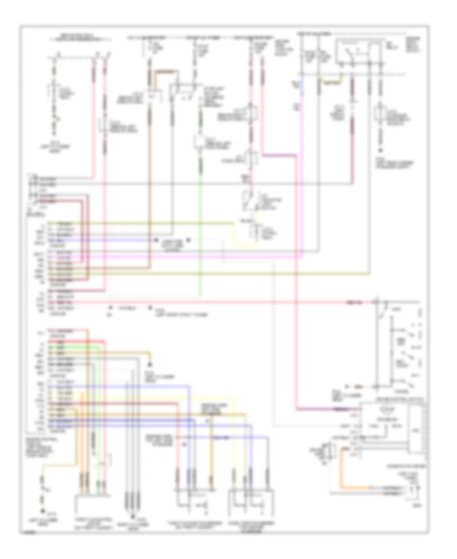
EXTERIOR LIGHTS
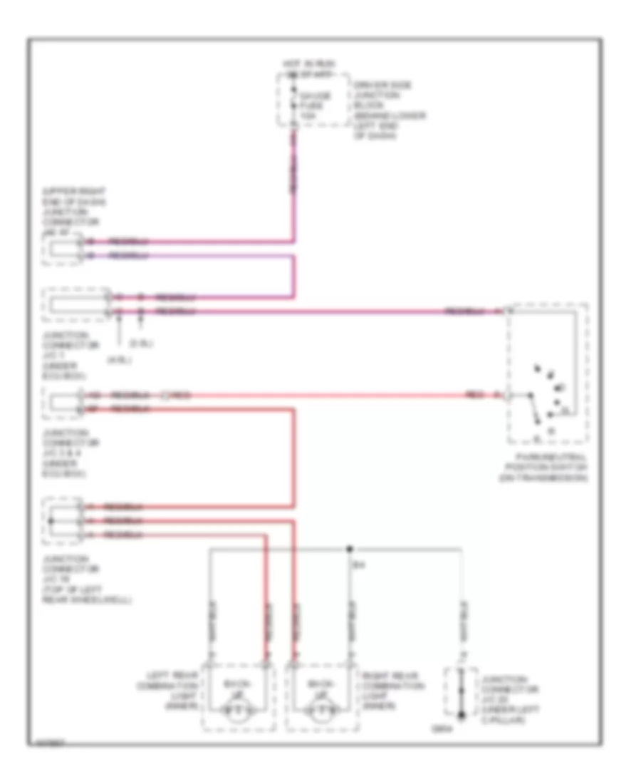
Back-up Lamps Wiring Diagram for Lexus GS 400 1998
List of elements for Back-up Lamps Wiring Diagram for Lexus GS 400 1998:
- (3.0l)
- (4.0l)
- (upper right end of dash) junction connector j/c 17
- Back- up
- Driver side junction block (behind lower left end of dash)
- G904
- Gauge fuse 10a
- Hot in run or start
- Junction connector j/c 1 (under ecu box)
- Junction connector j/c 19 (top of left rear wheelwell)
- Junction connector j/c 20 (under left c-pillar)
- Junction connector j/c 3 & 4 (under ecu box)
- Left rear combination light (inner)
- Park/neutral position switch (on transmission)
- Red
- Right rear combination light (inner)
Exterior Lamps Wiring Diagram (1 of 2) for Lexus GS 400 1998
List of elements for Exterior Lamps Wiring Diagram (1 of 2) for Lexus GS 400 1998:
- (dash harn, right side of dash) i6
- (left quarter panel) junction connector j/c 20
- (top of left rear wheelwell) junction connector j/c 19
- A15
- A19
- Auto
- Automatic light control sensor (behind upper left side of dash)
- B14
- B15
- Bdr
- Becu
- Body ecu 2
- Cltb
- Clte
- Clts
- Computer data lines system
- Cpub
- Cty
- Ctye
- D fr door fuse 20a
- Driver door ecu (in driver's door)
- Driver side junction block (behind lower left end of dash)
- Ecu-ig fuse 15a
- Engine room relay block 1 (on right side of engine compt, behind strut tower)
- G102 (left front strut tower)
- G200
- G904
- Grd
- Gswo
- H11
- H13
- Head
- Headlight switch
- Headlights system
- Hot at all times
- Hot in run or start
- Hrly
- Junction connector j/c 10 (upper left end of dash)
- Junction connector j/c 14 (behind combination meter)
- Junction connector j/c 19 (top of left rear wheel- well)
- Junction connector j/c 6 (left kick panel)
- Junction connector j/c 7 (left kick panel)
- Left front door courtesy switch
- Left front side marker light
- Left license plate light
- Left parking light
- Mpx-b fuse 10a
- Mpx1
- Mpx2
- Off
- Passenger side junction block (behind lower right end of dash)
- Red
- Right front side marker light
- Right license plate light
- Right parking light
- Sig
- Stop fuse 15a
- Stoplight switch (brake pedal bracket)
- Tail
- Trly
Exterior Lamps Wiring Diagram (2 of 2) for Lexus GS 400 1998
List of elements for Exterior Lamps Wiring Diagram (2 of 2) for Lexus GS 400 1998:
- (behind lower right end of dash) passenger side junction block
- (left front of trunk) b5
- (left kick panel)
- (left kick panel) g200
- (rear of left rear wheelwell) b4
- (top of left rear wheelwell) junction connector j/c 19
- A22
- Alt fuse 120a
- B11
- B5 (left front of trunk)
- Body computer system
- Brake lts
- C12
- C13
- Combination meter
- D10
- Driver side junction block (behind lower left end of dash)
- E11
- Engine room relay block (on right side of engine compt, behind strut tower)
- G102 (left front strut tower)
- G103 (right front strut tower)
- G200
- G904
- Gauge fuse 10a
- Grd
- Hazard switch
- Hi mount
- High mounted stop light (w/ rear spoiler)
- High mounted stop light (w/o rear spoiler)
- Hot at all times
- Hot in run or start
- Junction connector j/c 12 (behind combination meter)
- Junction connector j/c 17 (upper right end of dash)
- Junction connector j/c 20 (left quarter panel)
- Left
- Left & right rear combination lights (inner)
- Left front turn signal light
- Left rear combination light (outer)
- Left turn indic
- Lf signal
- Light failure sensor (at left side of luggage compartment)
- Markr
- Mpx2
- Noise filter (high mounted stop light) (at left front corner of luggage compt)
- Power
- Right
- Right front turn signal light
- Right rear combination light (outer)
- Right turn indic
- Side marker
- Stop
- Stop sw
- Stp
- Tail
- Tail fuse 10a
- Tail lts
- Tail relay
- Taillt pwr
- Turn
- Turn signal flasher (behind left side of dash)
- Turn signal light switch
- Turn-haz fuse 10a
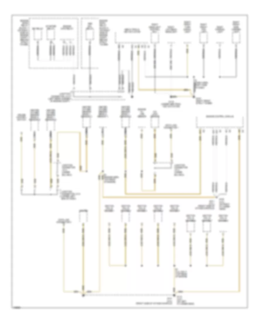
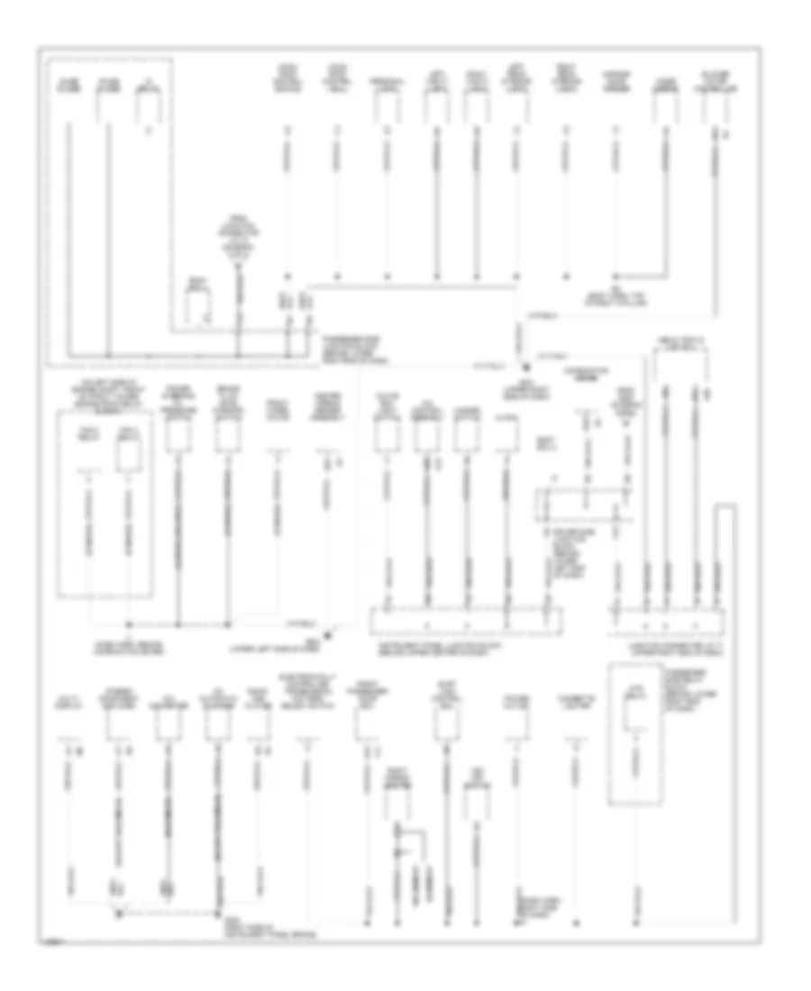
GROUND DISTRIBUTION
Ground Distribution Wiring Diagram (1 of 4) for Lexus GS 400 1998
List of elements for Ground Distribution Wiring Diagram (1 of 4) for Lexus GS 400 1998:
- (3.0l only)
- (4.0l only)
- (w/ hid)
- (w/o hid)
- A/c lock sensor
- A21
- A31
- Abs & trac & vsc actuator
- Abs sol relay
- B17
- Cruise control switch
- Data link connector 1
- Data link connector 3
- E1 (4.0l only) (top rear of engine)
- E1 (engine harn, top front of engine)
- Efi relay
- Engine control module
- Engine main relay
- Engine oil life sensor
- Engine room relay block 1 (on right side of engine compt, behind strut tower)
- Engine room relay block 2 (on right side of engine compt, behind strut tower)
- G103 (right front strut tower)
- G112 (4.0l) (on left cylinder head)
- G116 (under abs/trac/ vsc actuator)
- G120 (4.0l) (on right cylinder head)
- G131 (3.0l) (front side of intake mainfold)
- G131 (3.0l) (front side of intake manifold)
- Heated oxygen sensor (bank 1, sensor 1)
- Heated oxygen sensor (bank 1, sensor 2)
- Heated oxygen sensor (bank 2, sensor 1)
- Heated oxygen sensor (bank 2, sensor 2)
- I5 (dash harn, right side of dash)
- Igniter
- Ignition coil & igniter 1
- Ignition coil & igniter 2
- Ignition coil & igniter 3
- Ignition coil & igniter 4
- Ignition coil & igniter 5
- Ignition coil & igniter 6
- Ignition coil & igniter 7
- Ignition coil & igniter 8
- Junction connector j/c 2 (under ecu box)
- Junction connector j/c 4 (under ecu box)
- Junction connector j/c 5 (left rear corner of engine compt)
- Junction connector j/c 9 (upper left end of dash)
- Nca
- Right front fog light
- Right front side marker light
- Right front turn signal light
- Right headlight control ecu
- Right low beam headlight
- Right parking light
- Starter relay
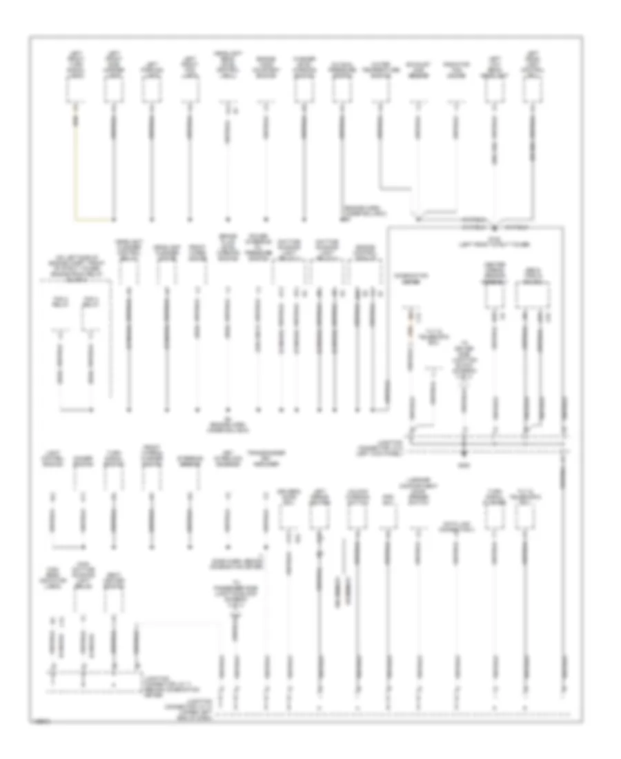
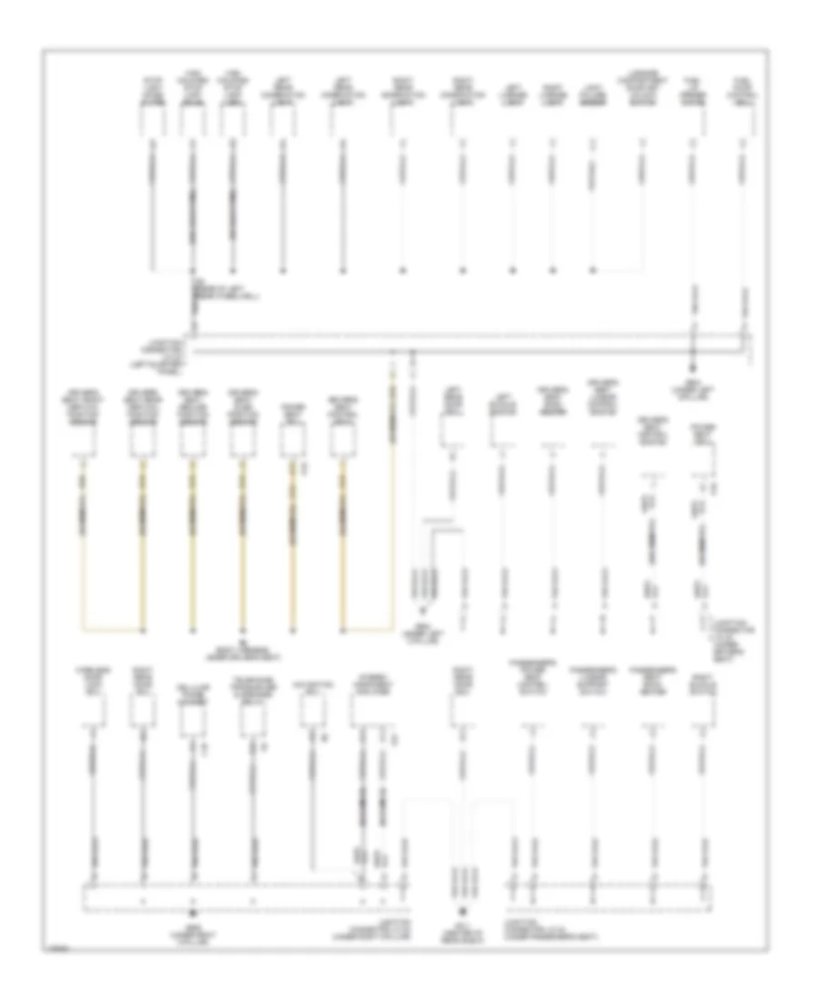
Ground Distribution Wiring Diagram (2 of 4) for Lexus GS 400 1998
List of elements for Ground Distribution Wiring Diagram (2 of 4) for Lexus GS 400 1998:
- (3.0l only)
- (canada)
- (engine harn, under ecu box) e4
- (on left side of engine compt, front of strut tower) engine room relay block 3
- (usa)
- (w/ hid)
- (w/o hid)
- A/c dual pressure switch
- A13
- A19
- A31
- Abs & trac & vsc ecu
- B28
- Brake fluid level warning switch
- C12
- C13
- Center airbag sensor assembly
- Combination meter
- D24
- D26
- Data link connector 3
- Daytime running light relay 3
- Daytime running light relay 4
- Dimmer switch
- Driver's door ecu
- E4 (engine harn, under ecu box)
- Engine control module
- Engine hood courtesy switch
- Exhaust gas sensor
- Fan 2 relay
- Fan 3 relay
- Front wiper & washer switch
- Front wiper motor
- G102 (left front strut tower)
- G200
- Headlight beam level control ecu
- Headlight cleaner control relay
- Headlight cleaner motor
- High beam indicator light
- I1 (dash harn, behind combination meter)
- Junction connector j/c 10 (upper left end of dash)
- Junction connector j/c 11 (behind combination meter)
- Junction connector j/c 6 (left kick panel)
- Key interlock solenoid
- Left front fog light
- Left front side marker light
- Left front turn signal light
- Left head- light control ecu
- Left low beam headlight
- Left mirror heater
- Left parking light
- Light control switch
- Luggage compartment door opener switch
- Main daytime running light relay
- Power steering oil pressure switch
- Pps ecu
- Radiator fan motor
- Seat heater switch
- Steering sensor
- Tilt & telescopic ecu
- To driver side junction block (diagram 3 of 4)
- To passenger side junction block (diagram 3 of 4)
- Transponder key amplifier
- Turn signal flasher
- Turn signal switch
- Unlock warning switch
- W/ memory
- W/o memory
- Washer level warning switch
- Water temperature switch
Ground Distribution Wiring Diagram (3 of 4) for Lexus GS 400 1998
List of elements for Ground Distribution Wiring Diagram (3 of 4) for Lexus GS 400 1998:
- (canada 3.0l only)
- (canada)
- (dash harn, right side of dash) i6
- (except nakamichi)
- (nakamichi)
- (on left side of engine compt, front of strut tower) engine room relay block 3
- A/c control assembly
- A12
- A13
- A20
- A22
- Abs & trac & vsc ecu
- B17
- B2 (body harn, top of right a-pillar)
- B27
- Blower motor controller
- Body ecu 1
- Body ecu 2
- Brake fluid level warning switch
- Cd automatic changer
- Center airbag sensor assembly
- Cigarette lighter
- Clock
- Combination meter
- D/a converter
- Driver side junction block (behind lower left end of dash)
- Electronically controlled transmission pattern select switch
- F11
- F13
- Fan 2 relay
- Fan 3 relay
- From g200 (diagram 2 of 4)
- From junction connector j/c 10 (diagram 2 of 4)
- Front passenger door ecu
- Front wiper motor
- G201 (upper right side of dash)
- G202 (upper left side of dash)
- G302 (right side of instrument panel brace)
- Garage door opener
- Glove box light switch
- Hazard switch
- Htr relay
- I1 (dash harn, behind combination meter)
- Ig relay
- Inner mirror
- Instrument panel junction block (behind upper center of dash)
- Junction connector j/c 17 (upper right end of dash)
- Left rear interior light
- Left vanity light
- Moon roof control ecu
- Moon roof control switch
- Multi- display
- Noise filter
- Passenger side junction block (behind lower right end of dash)
- Passenger side relay block (behind lower right end of dash)
- Personal light
- Power outlet
- Power steering oil pressure switch
- Radio and player
- Right mirror heater
- Right rear interior light
- Right vanity light
- Shift lock control ecu
- Stereo component amplifier
- Vsc off switch
- W/ memory
- W/o memory
Ground Distribution Wiring Diagram (4 of 4) for Lexus GS 400 1998
List of elements for Ground Distribution Wiring Diagram (4 of 4) for Lexus GS 400 1998:
- (nakamichi)
- (w/ memory)
- (w/ rear wing)
- (w/o memory)
- (w/o rear wing)
- A22
- B13
- B4 (rear of left rear wheelwell)
- B6 (body harness, under driver's seat)
- C18
- Cellular phone handset
- Driver's seat back heater
- Driver's seat control seat
- Driver's seat control switch
- Driver's seat front vertical position sensor
- Driver's seat lumbar control switch
- Driver's seat rear vertical position sensor
- Driver's seat recline position sensor
- Driver's seat slide position sensor
- Fuel lid opener motor
- Fuel pump control ecu
- G311 (center of rear shelf)
- G904 (under left c-pillar)
- G905 (under right c-pillar)
- High mounted stop light (bulb)
- High mounted stop light (led)
- Junction connector j/c 20 (left quarter panel)
- Junction connector j/c 22 (under right c-pillar)
- Junction connector j/c 23 (under driver's seat)
- Junction connector j/c 24 (under passenger's seat)
- Left buckle switch
- Left license light
- Left rear combination light
- Left rear door ecu
- Light failure sensor
- Luggage compartment door key unlock switch
- Navigation ecu
- P19
- Passenger's lumbar support switch
- Passenger's power seat control switch
- Passenger's seat back heater
- Power seat ecu
- Right buckle switch
- Right license light
- Right rear combination light
- Right rear door ecu
- S17
- Stereo component amplifier
- Stop light noise filter
- Telephone transceiver & speaker relay
- Wireless door lock ecu
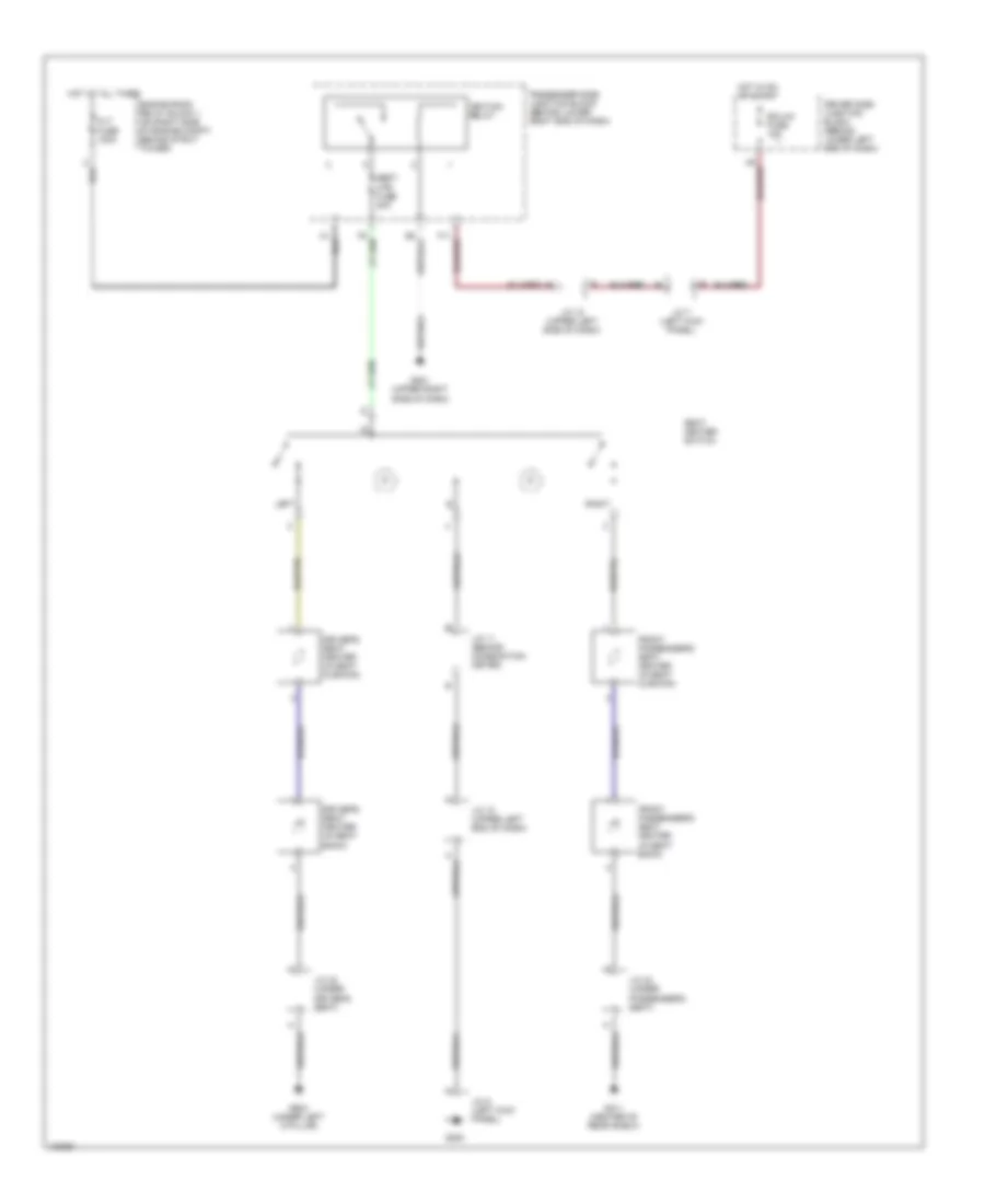
HEADLIGHTS
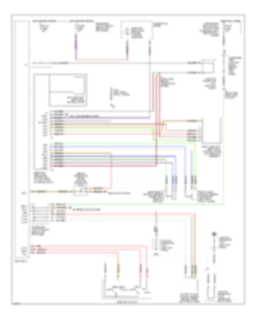
Headlamps Wiring Diagram, with DRL (1 of 2) for Lexus GS 400 1998
List of elements for Headlamps Wiring Diagram, with DRL (1 of 2) for Lexus GS 400 1998:
- (dash harn, right side of dash) i6
- (left front strut tower) g102
- (left kick panel) junction connector j/c 7
- A10
- A15
- A17
- Altl
- Auto
- Automatic light control sensor (behind upper left side of dash)
- B10
- B14
- B15
- Bdr
- Becu
- Body ecu 2
- Cltb
- Clte
- Clts
- Computer data lines system
- Cpub
- Cty
- Ctye
- D fr door fuse 20a
- Dimmer switch
- Driver door ecu (in driver's door)
- Driver side junction block (behind lower left end of dash)
- Ecu-ig fuse 15a
- Engine room relay block 1 (on right side of engine compt, behind strut tower)
- Exterior lights system
- Ffgo
- Ffog
- Flash
- Fog lights
- Fog relay
- Foglight switch
- Fr fog fuse 15a
- G103 (right front strut tower)
- G200
- Gauge fuse 10a
- Grd
- Gswo
- H11
- H13
- Head
- Headlight switch
- High
- Hot at all times
- Hot in start or run
- Hrly
- Junction connector j/c 10 (upper left end of dash)
- Junction connector j/c 17 (upper right end of dash)
- Junction connector j/c 6 (left kick panel)
- Left front door courtesy switch
- Left front fog light
- Low
- Mpx-b fuse 10a
- Mpx1
- Mpx2
- Off
- Passenger side junction block (behind lower right end of dash)
- Red
- Right front fog light
- Sig
- Tail
- Trly
Headlamps Wiring Diagram, with DRL (2 of 2) for Lexus GS 400 1998
List of elements for Headlamps Wiring Diagram, with DRL (2 of 2) for Lexus GS 400 1998:
- (on right side of engine compt, behind strut tower) engine room relay block
- A15
- Combination meter
- Daytime running light relay 3 & 4 (at left front corner of engine compt)
- Dimmer drl 2 relay
- Drl 1 fuse 30a
- Drl 2 fuse 30a
- Ecu-b2 fuse 5a
- Engine room relay block 1 (on right side of engine compt, behind strut tower)
- Engine room relay block 3 (on left side of engine compt, front of strut tower)
- G102 (left front strut tower)
- G103 (right front strut tower)
- Head lp relay
- Headlights system (headlight beam level control ecu)
- Hi beam indic
- Hot at all times
- Junction connector j/c 11 (behind combo meter)
- Junction connector j/c 14 (behind combination meter)
- Junction connector j/c 15 (behind combo meter)
- Junction connector j/c 18 (right kick panel)
- Left high beam headlight
- Left low beam headlight
- Left lower head fuse 15a
- Left upper head fuse 15a
- Main daytime running light relay (behind right end of dash)
- Main fuse 40a
- Parking brake switch (behind left side of dash)
- Passenger side junction block (behind lower right end of dash)
- Pnk
- Red
- Right high beam headlight
- Right low beam headlight
- Right lower head fuse 15a
- Right upper head fuse 15a
Headlamps Wiring Diagram, without DRL (1 of 2) for Lexus GS 400 1998
List of elements for Headlamps Wiring Diagram, without DRL (1 of 2) for Lexus GS 400 1998:
- (dash harn, right side of dash) i6
- (left front strut tower) g102
- (left kick panel) junction connector j/c 7
- A15
- A17
- A19
- Auto
- Automatic light control sensor (behind upper left side of dash)
- B10
- B14
- B15
- Bdr
- Becu
- Body ecu 2
- Cltb
- Clte
- Clts
- Computer data lines system
- Cpub
- Cty
- Ctye
- D fr door fuse 20a
- Dimmer switch
- Driver door ecu (in driver's door)
- Driver side junction block (behind lower left end of dash)
- Ecu-ig fuse 15a
- Engine room relay block 1 (on right side of engine compt, behind strut tower)
- Exterior lights system
- Ffgo
- Ffog
- Flash
- Fog lights
- Fog relay
- Foglight switch
- Fr fog fuse 15a
- G103 (right front strut tower)
- G200
- Grd
- Gswo
- H11
- H13
- Head
- Headlight switch
- High
- Hot at all times
- Hot in run or start
- Hrly
- Junction connector j/c 10 (upper left end of dash)
- Junction connector j/c 6 (left kick panel)
- Left front door courtesy switch
- Left front fog light
- Low
- Mpx-b fuse 10a
- Mpx1
- Mpx2
- Off
- Passenger side junction block (behind lower right end of dash)
- Red
- Right front fog light
- Sig
- Tail
- Trly
Headlamps Wiring Diagram, without DRL (2 of 2) for Lexus GS 400 1998
List of elements for Headlamps Wiring Diagram, without DRL (2 of 2) for Lexus GS 400 1998:
- A14
- A15
- B11
- Combination meter
- Driver side junction block (behind lower left end of dash)
- Engine room relay block 1 (on right side of engine compt, behind strut tower)
- Engine room relay block 3 (on left side of engine compt, front of strut tower)
- G102 (left front strut tower)
- G103 (right front strut tower)
- Head lp relay
- Headlights system (headlight beam level control ecu)
- Hi beam indic
- Hot at all times
- Junction connector j/c 14 (behind combination meter)
- Junction connector j/c 15 (behind combination meter)
- Left high beam headlight
- Left low beam headlight
- Left low beam headlight control ecu
- Left lower head fuse 15a
- Left upper head fuse 15a
- Main fuse 40a
- Mpx buss
- Pnk
- Pwr
- Red
- Right high beam headlight
- Right low beam headlight
- Right low beam headlight control ecu
- Right lower head fuse 15a
- Right upper head fuse 15a
- Srs-b fuse 5a
- W/ hid
- W/o hid
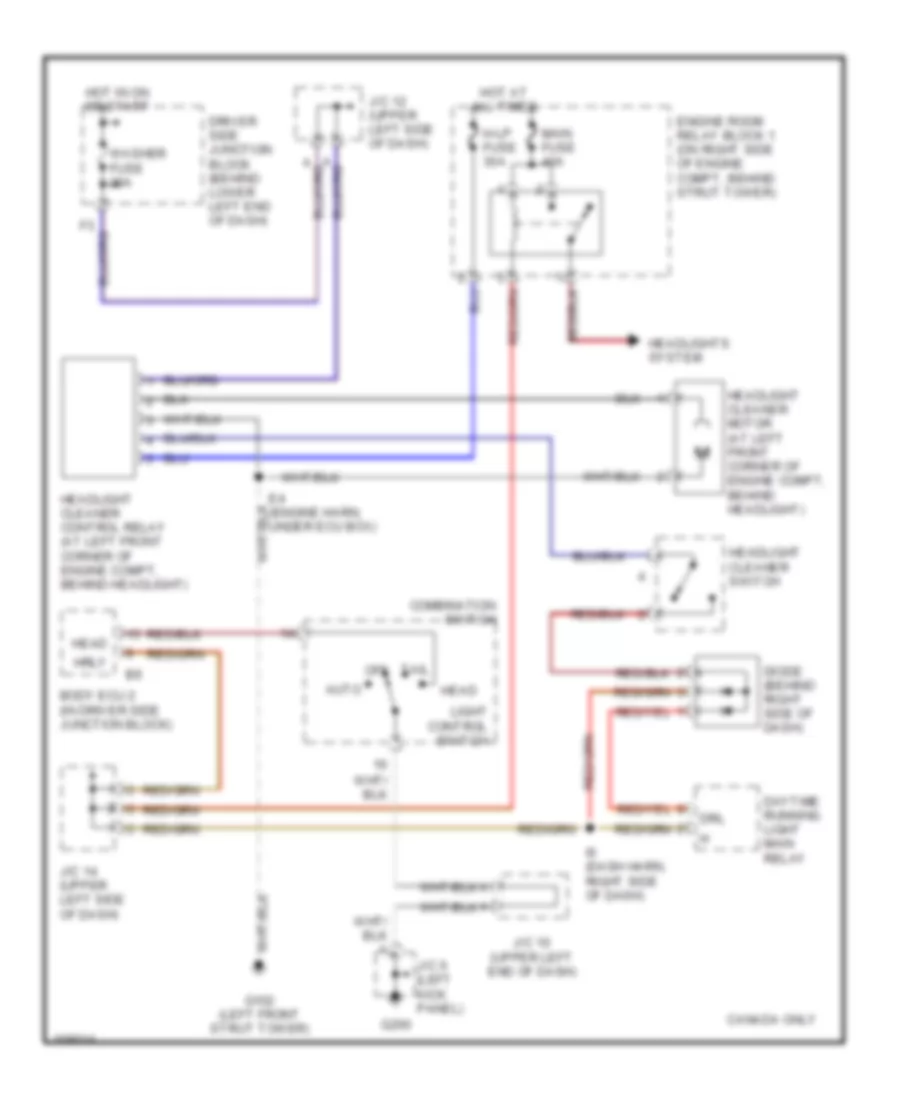
Headlamps Leveling Wiring Diagram for Lexus GS 400 1998
List of elements for Headlamps Leveling Wiring Diagram for Lexus GS 400 1998:
- (behind combination meter) junction connector j/c 14
- A15
- Anti-lock brakes system
- Auto
- Automatic light control sensor (behind upper left side of dash)
- Becu
- Body ecu 2
- Cltb
- Clte
- Clts
- Combination meter
- Driver side junction block (behind left kick panel)
- E1 (grd)
- Ecu-ig fuse 15a
- Engine room relay block 1 (on right side of engine compt, behind strut tower)
- Exterior lights system
- Front height control sensor (forward of left front strut tower)
- G102 (left front strut tower)
- G200
- Gauge fuse 10a
- Grd
- H13
- Hdlp
- Head
- Headlight beam level control ecu (at left front of engine compt)
- Headlight beam level control warning indicator
- Headlight switch
- Headlights system
- Hot at all times
- Hot in start or run
- Hrly
- I1 (dash harn, behind combination meter)
- I6 (dash harn, right side of dash)
- Junction connector j/c 10 (upper left end of dash)
- Junction connector j/c 6 (left kick panel)
- Junction connector j/c 7 (left kick panel)
- Left headlight beam level control motor
- Lhb1
- Mpx-b fuse 10a
- Off
- Passenger side junction block (behind right kick panel)
- Rear height control sensor (under left rear of vehicle)
- Red
- Rh1
- Rh2
- Rh3
- Rh4
- Right headlight beam level control motor (on headlight assembly)
- Sbf
- Sbr
- Sgf
- Sgr
- Shf
- Shr
- Spdl
- Tail
- Trly
- Wng
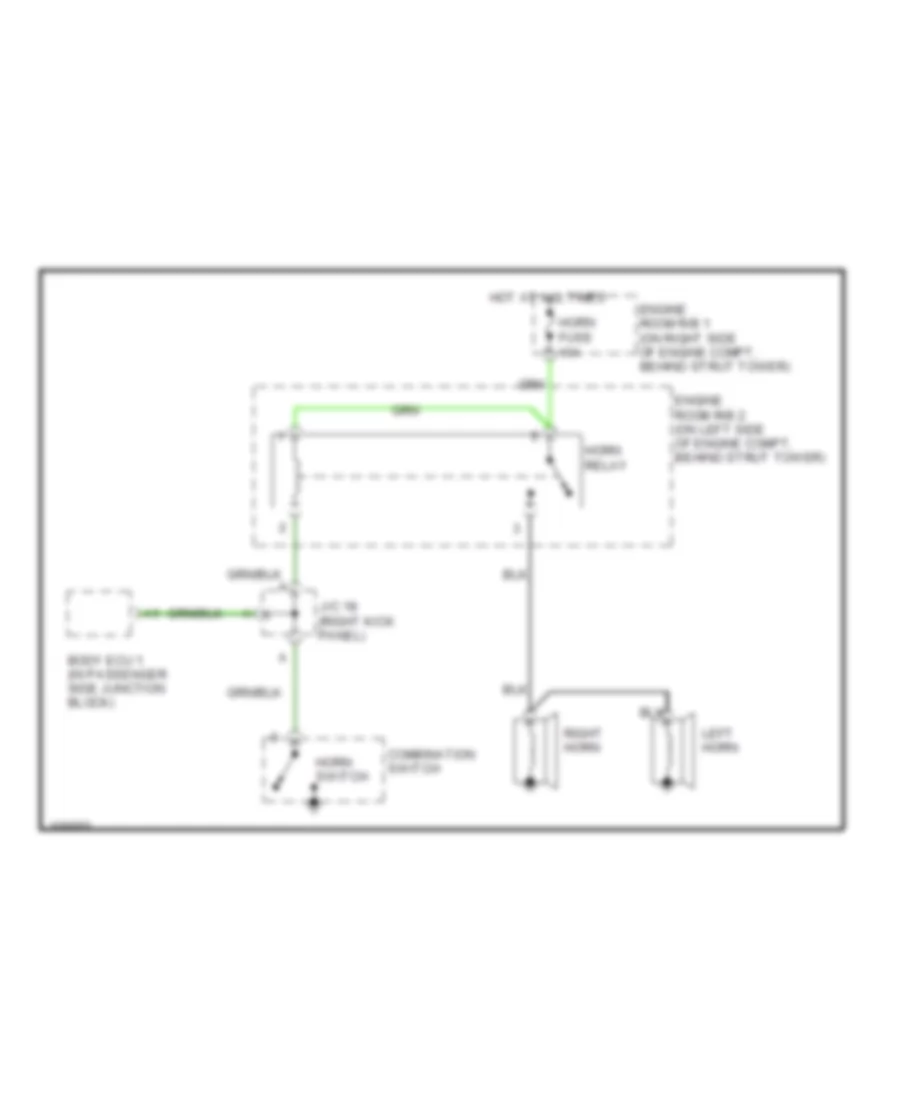
HORN
Horn Wiring Diagram for Lexus GS 400 1998
List of elements for Horn Wiring Diagram for Lexus GS 400 1998:
- Body ecu 1 (in passenger side junction block)
- Combination switch
- Engine room r/b 1 (on right side of engine compt, behind strut tower)
- Engine room r/b 2 (on left side of engine compt, behind strut tower)
- Horn fuse 10a
- Horn relay
- Horn switch
- Hot at all times
- J/c 18 (right kick panel)
- Left horn
- Right horn
INSTRUMENT CLUSTER
Instrument Cluster Wiring Diagram for Lexus GS 400 1998
List of elements for Instrument Cluster Wiring Diagram for Lexus GS 400 1998:
- (canada)
- (usa)
- 1998-00
- A/t p
- A10
- A11
- A12
- A13
- A14
- A15
- A16
- A16 a1
- A17
- A18
- A19
- A20
- A21
- A22
- Abs ind
- Anti-lock brake system
- B10
- B11
- B12
- B13
- B14
- B15
- B16
- B17
- B18
- Body ecu 2 (in driver's side junction block)
- Brake ind
- Buzzer
- C12
- C13
- Center air bag sensor assambly (behind center of dash, forward of center console)
- Charge ind
- Combination meter
- Cpu
- Cruise ind
- Door ind
- Driver side junction block (behind left kick panel)
- Ect power ind
- Ect snow ind
- Engine controls system
- Engine room relay block 1 (right side of engine compt, behind strut tower)
- Exterior lights system
- F13
- Fuel gauge
- Fuel ind
- Fuel sender (in fuel tank)
- Fuel sender (sub) (in fuel tank)
- G102 (left front strut tower)
- G200
- G201 (upper right side of dash)
- Gauge fuse 10a
- Head ind
- Headlight leveling ind
- Headlights system
- High beam ind
- Hot at all times
- Hot in run or start
- Interior lights system
- J/c 10 (behind left side of dash)
- J/c 11 (behind left side of dash)
- J/c 17 (behind right side of dash)
- J/c 6 (left kick panel)
- Left turn ind
- M (gs400) 4 (gs300)
- Malfunction ind lamp
- Mpx-b fuse 10a
- Odo/trip
- Odometer/ tripmeter
- Oil level ind
- Oil press ind
- Passenger side junction block (behind right kick panel)
- Pnk
- Rear light ind
- Red
- Reset
- Rheostat
- Right turn ind
- Seat belt ind
- Slip ind
- Speedometer
- Srs ind
- Srs-b fuse 5a
- Tachometer
- Tail ind
- Tilt & and telescopic ecu (behind left side of dash)
- Vsc ind
- Vsc off ind
- Warning system
- Washer ind
- Washer level warning switch (left front of engine compt)
- Water temp gauge
INTERIOR LIGHTS
Courtesy Lamps Wiring Diagram (1 of 3) for Lexus GS 400 1998
List of elements for Courtesy Lamps Wiring Diagram (1 of 3) for Lexus GS 400 1998:
- (1998 - 2000)
- (dash harn, right side of dash)
- A10
- A12
- A13
- A19
- B14
- B15
- Bdr
- Becu
- Body ecu 2
- C12
- C18
- Computer data lines system
- Cpub
- Cty
- Ctyb
- Ctye
- D fr door fuse 20a
- D rr door fuse 20a
- Door
- Driver door ecu (in driver's door)
- Driver side junction block (behind left kick panel)
- Ecu-ig fuse 15a
- Exterior lights system
- G200
- Grd
- Gswo
- H10
- H11
- H13
- Headlights system
- Hot at all times
- Hot in run or acc
- Hot in run or start
- Hrly
- I1 (dash harn, behind combination meter)
- Ignition key cylinder light
- Ile
- Junction connector j/c 10 (behind left end of dash)
- Junction connector j/c 13 (behind combination meter)
- Junction connector j/c 6 (left kick panel)
- Junction connector j/c 7 (left kick panel)
- Junction connector j/c 8 (behind left kick panel)
- Left front door courtesy light
- Left front door courtesy switch
- Left step light
- Mpx1
- Mpx2
- Passenger side junction block (behind right kick panel)
- Personal light
- Radio 2 fuse 15a
- Right step light
- Sig
- Trly
Courtesy Lamps Wiring Diagram (2 of 3) for Lexus GS 400 1998
List of elements for Courtesy Lamps Wiring Diagram (2 of 3) for Lexus GS 400 1998:
- (dash harn, behind comb- ination meter)
- B2 (body harn, top of right a- pillar)
- Bdr
- Cpub
- Cty
- Ctyb
- Ctye
- Diode (luggage compartment door open detection) (at left side of luggage compartment)
- Engine room relay block 1 (on right side of engine compt, behind strut tower)
- G311 (center of rear shelf)
- G904
- G904 (under left c-pillar)
- G905
- Grd
- Hot at all times
- Junction connector j/c 20 (above left rear wheelwell)
- Junction connector j/c 22 (above right rear wheewell)
- Left rear door courtesy light
- Left rear door courtesy switch
- Left rear door ecu (in left rear door)
- Left rear interior light
- Left vanity light
- Luggage compartment door courtesy switch
- Luggage compartment light
- Mpx-b fuse 10a
- Mpx1
- Mpx2
- Noise filter (stoplight) (at left front corner of luggage compt)
- Passenger side junction block (behind right kick panel)
- Power seat ecu (behind left side of dash)
- Red
- Right rear door courtesy light
- Right rear door courtesy switch
- Right rear door ecu (in right rear door)
- Right rear interior light
- Right vanity light
- Rrlp
- Sig
- W/ memory seats
- W/o memory seats
Courtesy Lamps Wiring Diagram (3 of 3) for Lexus GS 400 1998
List of elements for Courtesy Lamps Wiring Diagram (3 of 3) for Lexus GS 400 1998:
- (1998 - 2000)
- (above right right wheelwell)
- (at right side of luggage compartment) wireless door lock ecu
- (left rear corner of engine compt) wireless door lock buzzer
- A12
- A13
- A15
- A18
- A19
- Acc
- B14
- B15
- Bdr
- Becu
- Body ecu 1
- Bsub
- Bzr
- Bzr2
- C10
- C12
- Computer data lines system
- Cpub
- Cty
- Ctyb
- Ctye
- Dome fuse 10a
- F11
- Front passenger door ecu (in right front door)
- G201 (upper right side of dash)
- G905
- Grd
- Gsw
- H11
- H12
- Hot at all times
- Junction connector j/c 15 (behind left side of dash)
- Junction connector j/c 17 (upper right end of dash)
- Junction connector j/c 22
- Mpx1
- Mpx2
- P fr door fuse 20a
- P rr door fuse 20a
- Passenger side junction block (behind right kick panel)
- Pnk
- Rco
- Rda
- Right front door courtesy light
- Right front door courtesy switch
- Rssi
- Sig
Instrument Illumination Wiring Diagram for Lexus GS 400 1998
List of elements for Instrument Illumination Wiring Diagram for Lexus GS 400 1998:
- (behind combination meter) junction connector j/c 16
- (behind left side of dash) junction connector j/c 13
- A/c control assembly
- A/t shift position illumination
- A13
- Anti-theft system
- C12
- Cigarette lighter
- Combination meter
- Driver side j/b (behind left kick panel)
- Driver side junction block (behind left kick panel)
- Driver side junction block (behind lower left end of dash)
- Electronically controlled transmission pattern select switch
- G200
- G311 (center of rear shelf)
- G904 (under left c-pillar)
- Glove box light
- Glove box light switch
- Grd
- Hazard switch
- Headlight cleaner switch (canada)
- Hot in park or head
- I1 (dash harn, behind combination meter)
- Instrument panel junction block (behind upper center of dash)
- Junction connector j/c 6 (left kick panel)
- Left rear ashtray illumination
- Left rear door ecu (in left rear door)
- Mirror retraction switch
- Multi-display
- Panel fuse 7.5a
- Radio & player
- Remote control mirror switch
- Rheostat (security indicator light)
- Right rear ashtray illumination
- Right rear door ecu (in right rear door)
- Seat heater switch
- Vsc off switch
- Whe1
MEMORY SYSTEMS
Memory System Wiring Diagrams (1 of 2) for Lexus GS 400 1998
List of elements for Memory System Wiring Diagrams (1 of 2) for Lexus GS 400 1998:
- (left side of dash) j/c 13
- Bdr
- Becu
- Body ecu 1
- Body ecu 2
- Computer data lines system
- Cpub
- D fr door fuse 20a
- D22
- D23
- D24
- De2
- Dm+r
- Dmhr
- Dmvr
- Down
- Driver door ecu (in driver's door)
- Driver side junction block (behind lower left end of dash)
- Driving position and memory control switch
- Dvc
- Ecu-ig fuse 15a
- Engine room relay block 1 (on right side of engine compartment, behind strut tower)
- F11
- F12
- F13
- G200
- G201 (upper right side of dash)
- Gnd
- Gswo
- H10
- H11
- Hot at all times
- Hot in accy or run
- Hot in on or start
- Hsr
- Hssr
- I6 (dash harn, right side of dash)
- J/c 10 (upper left end of dash)
- J/c 15 (left side of dash)
- J/c 17 (upper right end of dash)
- J/c 6 (left kick panel)
- J/c 7 (left kick panel)
- J/c 8 (left kick panel)
- Left
- Left remote control mirror
- Mem 1
- Mem 2
- Mirb
- Mire
- Mirs
- Mpx-b fuse 10a
- Mpx1
- Mpx2
- Mswe
- Operation switch
- P fr door fuse 20a
- Passenger door ecu (in right front door)
- Passenger junction block (behind lower right end of dash)
- Pe2
- Pm+r
- Pmhr
- Pmvr
- Pnk
- Pvc
- Radio 2 fuse 15a
- Red
- Remote control mirror switch
- Right
- Right remote control mirror
- Select switch
- Set
- Sig
- Vsr
- Vssr
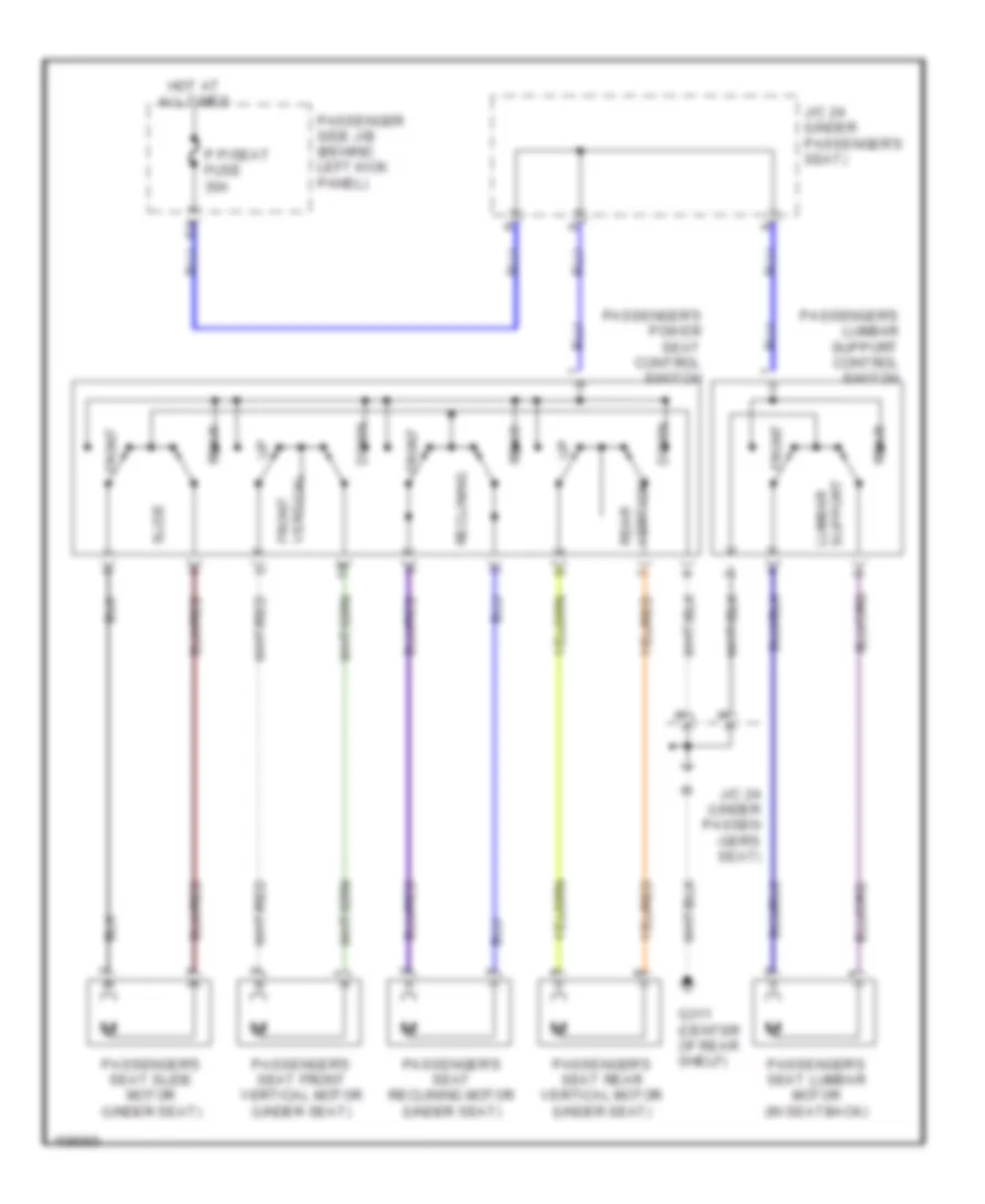
Memory System Wiring Diagrams (2 of 2) for Lexus GS 400 1998
List of elements for Memory System Wiring Diagrams (2 of 2) for Lexus GS 400 1998:
- (body harness, under driver's seat)
- (upper left end of dash) j/c 10
- Computer data lines system
- D p/seat fuse 30a
- Down
- Driver side junction block (behind lower left end of dash)
- Driver's seat front vertical motor
- Driver's seat lumbar support control motor
- Driver's seat rear vertical motor
- Driver's seat reclining motor
- Driver's seat sliding motor
- Ecu-b2 fuse 5a
- Ecub
- Ecue
- Fdwn
- Front
- Front vertical control sensor
- Frv+
- Frv-
- Fup
- G200
- G904
- G904 (under left c-pillar)
- Gnd
- Hot at all times
- J/c 18 (right kick panel)
- J/c 20 (left quarter panel)
- J/c 23 (below driver's seat)
- J/c 6 (left kick panel)
- Ldwn
- Lft+
- Lft-
- Lumbar support control switch
- Lup
- Mpx1
- Mpx2
- Msw
- P p/seat fuse 30a
- P18
- P19
- Passenger junction block (behind lower right end of dash)
- Power seat control switch
- Power seat ecu (under driver's seat)
- Power telescopic motor
- Power tilt motor
- Pvcc
- Rcl+
- Rcl-
- Rclf
- Rclr
- Rear
- Rear vertical control sensor
- Recline control sensor
- Sgnd
- Sld+
- Sld-
- Sldf
- Sldr
- Slide control sensor
- Ssfv
- Ssrl
- Ssrr
- Ssrs
- Sysb
- Tel lng
- Tel shrt
- Tem+
- Tem-
- Tilt and telescopic ecu (behind left side of dash)
- Tilt and telescopic switch
- Tilt down
- Tilt up
- Tim+
- Tim-
NAVIGATION
Navigation Wiring Diagram for Lexus GS 400 1998
List of elements for Navigation Wiring Diagram for Lexus GS 400 1998:
- (right side of instrument panel brace) g302
- +b1
- Acc
- Air conditioning system
- Aui+
- Aui-
- Auo+
- Auo-
- Braided
- C 1995 vftc
- Driver side junction block (behind lower left end of dash)
- Fl+
- Fl-
- G311 (center of rear shelf)
- Grd1
- Hot at all times
- Hot in accy or run
- Illum
- Instrument cluster system
- Instrument panel junction block (behind upper center of dash)
- Interior lights system
- Junction connector j/c 22 (under right c-pillar)
- Left front door speaker
- Memory systems
- Mpx1
- Mpx2
- Multi-display
- Navigation ecu (at right rear corner of luggage compt)
- Passenger side junction block (behind lower right end of dash)
- Pnk
- Radio & player
- Radio 2 fuse 15a
- Red
- Spd (vss)
- Stereo component amplifier (except nakamichi: behind right side of dash) (nakamichi: at right rear corner of luggage compt)
- Sync
- Tv fuse 15a
- Tx+
- Tx-
- Tx1+
- Tx1-
PASSIVE RESTRAINTS
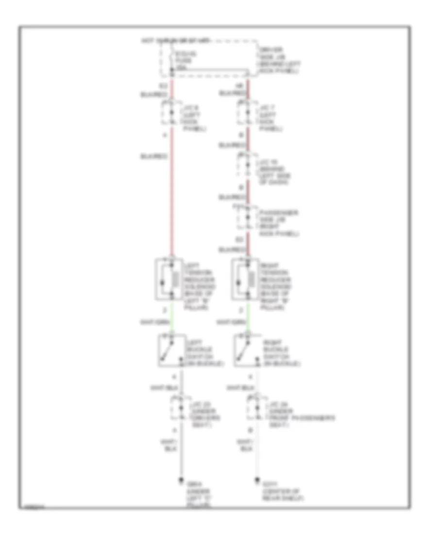
Passive Restraint Wiring Diagram for Lexus GS 400 1998
List of elements for Passive Restraint Wiring Diagram for Lexus GS 400 1998:
- Driver side j/b (behind left kick panel)
- Ecu-ig fuse 15a
- F11
- G311 (center of rear shelf)
- G904 (under left "c" pillar)
- Hot in run or start
- J/c 15 (behind left side of dash)
- J/c 23 (under driver's seat)
- J/c 24 (under front passenger's seat)
- J/c 7 (left kick panel)
- J/c 8 (left kick panel)
- Left buckle switch (in buckle)
- Left tension reducer solenoid (base of left "b" pillar)
- Passenger side j/b (right kick panel)
- Right buckle switch (in buckle)
- Right tension reducer solenoid (base of right "b" pillar)
POWER DISTRIBUTION
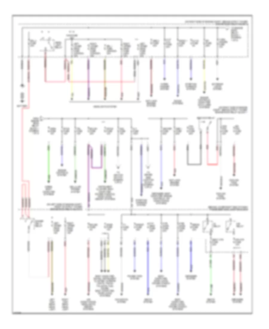
Power Distribution Wiring Diagram (1 of 2) for Lexus GS 400 1998
List of elements for Power Distribution Wiring Diagram (1 of 2) for Lexus GS 400 1998:
- (behind lower right end of dash) passenger side junction block
- (canada)
- (on left side of engine compt, front of strut tower) engine room relay block 3
- (on right side of engine compt, behind strut tower) engine room relay block 1
- (usa)
- Abs 1 fuse 60a
- Abs 2 fuse 40a
- Air conditioning, headlights, memory systems
- Alt fuse 120a
- Alt-s fuse 5a
- Am2 fuse 15a
- Anti-lock brakes system
- Battery
- Body computer, door locks, power window systems
- Body computer, sound, instrument cluster, interior lights, trunk, tailgate, fuel doors, body computer, door locks systems
- Cds fan fuse 30a
- Cellular phones system
- Cooling fans system
- Defog fuse 30a
- Defogger system
- Defogger, body computer, engine controls, air conditioning systems
- Dimmer drl 2 relay
- Dome fuse 10a
- Drl 1 fuse (canada) 30a
- Drl 2 fuse 30a
- Ecu-b1 fuse 20a
- Ecu-b2 fuse 5a
- Efi fuse 25a
- Eng main relay
- Engine controls system
- Engine controls, computer data lines systems
- Etcs fuse 15a
- Exterior lights system
- Fan main fuse 50a
- From a engine room relay block 1 (diagram 1 of 2)
- H-lp cln fuse 30a
- H10
- H12
- Head- light relay
- Headlights system
- Heater fuse 50a
- Horn fuse 10a
- Horns, body computer systems
- Ig relay
- Instrument cluster, body computer, power windows, door locks, memory systems
- Left high beam head- light
- Left lower head fuse (canada) 15a
- Left upper head fuse (usa) 10a
- Left upper head fuse 15a
- Main fuse 40a
- Mir htr fuse 10a
- Mir relay
- Mpx-b fuse 10a
- Navigation system
- P fr door fuse 20a
- P p/ seat fuse 30a
- P rr door fuse 20a
- Power tops system
- Radio 1 fuse 20a
- Rdi fan fuse 30a
- Red
- Right high beam head- light
- Right lower head fuse (canada) 15a
- Right upper head fuse (usa) 10a
- Right upper head fuse 15a
- S/roof fuse 25a
- Seat htr fuse 20a
- Seats system
- Sound systems
- Starting/ charging system
- Tel fuse 15a
- To driver side junction block (diagram 2 of 2)
- To engine room relay block 1 (diagram 1 of 2)
- To ignition switch (diagram 2 of 2)
- Turn/ hazard fuse 10a
- Tv fuse 15a
- Wiper/ washer system
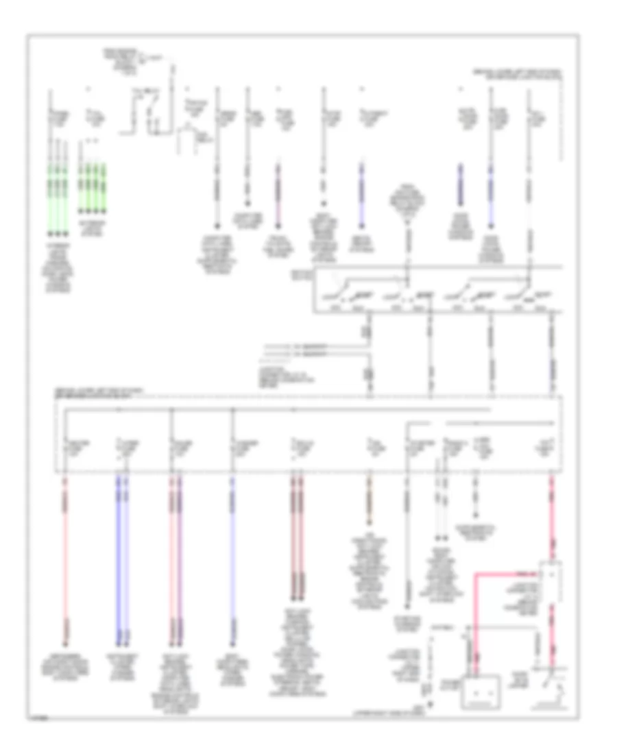
Power Distribution Wiring Diagram (2 of 2) for Lexus GS 400 1998
List of elements for Power Distribution Wiring Diagram (2 of 2) for Lexus GS 400 1998:
- (behind lower left end of dash) driver side junction block
- Acc
- Am 1 fuse 40a
- Anti-lock brakes, instrument cluster, computer data lines, headlights, engine controls, exterior lights shift interlock systems
- Anti-lock brakes, warning, instrument cluster, cellular phones, door locks, power windows, headlights, power tops, mirrors, electronic power steering, seats, memory, body computers systems
- Body computer, anti-lock brakes, engine controls, exterior lights systems
- Body computers, headlights, wiper/ washer systems
- Cicar- ette lighter
- Cig fuse 15a
- Computer data lines system
- D fr door fuse 20a
- D p/seat fuse 30a
- D rr door fuse 20a
- Defoggers, air conditioning engine controls, body computers systems
- Door locks, power windows systems
- E11
- Ecu-ig fuse 15a
- Exterior lights system
- F10
- Fog relay
- Fr fog fuse 15a
- From am2 fuse, engine room relay block (diagram 1 of 2)
- From engine room relay block 1 (diagram 1 of 2)
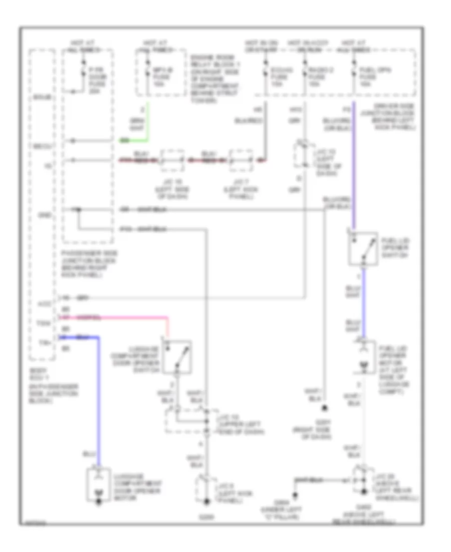
- Fuel opn fuse 10a
- G201 (upper right side of dash)
- Gauge fuse 10a
- H10
- H12
- Heater fuse 10a
- Ign fuse 5a
- Ignition switch
- Instrument cluster, wiper/ washer systems
- Interior lights, trans- missions, navigation, door locks, power windows systems
- Junction connector j/c 12 (behind combination meter)
- Junction connector j/c 15 (behind combination meter)
- Junction connector j/c 17 (upper right end of dash)
- Lock
- Obd fuse 7.5a
- Panel fuse 7.5a
- Pnk
- Power outlet
- Radio 2 fuse 15a
- Run
- Seats, memory systems
- Sound, body computer, air con- ditioning, instrument cluster, navigation, shift interlock systems
- Srs acc fuse 15a
- Srs-b fuse 5a
- Start
- Starter fuse 5a
- Starting/ charging system
- Stop fuse 15a
- Tail fuse 10a
- Tail relay
- Trunk, tailgate, fuel doors system
- Washer fuse 20a
- Wiper fuse 25a
POWER DOOR LOCKS
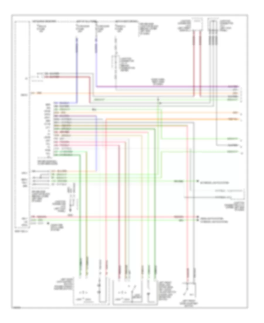
Keyless Entry & Anti-Theft Wiring Diagram (1 of 3) for Lexus GS 400 1998
List of elements for Keyless Entry & Anti-Theft Wiring Diagram (1 of 3) for Lexus GS 400 1998:
- (dash harn, right side of dash)
- A13
- A15
- A17
- A19
- B14
- B15
- Bdr
- Becu
- Body ecu 2
- C12
- C18
- Computer data lines system
- Cpub
- Cty
- Ctye
- D fr door fuse 20a
- D rr door fuse 20a
- Driver door ecu (in driver's door)
- Driver side junction block (behind lower left end of dash)
- Ecu-ig fuse 15a
- Exterior lights system
- G200
- Grd
- Gswo
- H10
- H11
- H13
- Headlights system
- Hot at all times
- Hot in accy or run
- Hot in run or start
- Hrly
- Ile
- Interior lights system
- Junction connector j/c 10 (upper left end of dash)
- Junction connector j/c 13 (behind combination meter)
- Junction connector j/c 6 (left kick panel)
- Junction connector j/c 7 (left kick panel)
- Junction connector j/c 8 (left front door sill)
- Kul
- Left door lock control switch (power window master switch)
- Left front door courtesy switch
- Left front door lock motor, door key lock & unlock switch & door lock detection switch
- Lock
- Lock detect
- Lsw
- Lswe
- Mpx1
- Mpx2
- Mul
- Pwe
- Radio 2 fuse 15a
- Sig
- Trly
- Unlk
Keyless Entry & Anti-Theft Wiring Diagram (2 of 3) for Lexus GS 400 1998
List of elements for Keyless Entry & Anti-Theft Wiring Diagram (2 of 3) for Lexus GS 400 1998:
- Bdr
- Cpub
- Cty
- Ctye
- Diode (luggage compartment door open detection) (at left side of luggage compt)
- Engine hood courtesy switch
- Engine room relay block 1 (on right side of engine compt, behind strut tower)
- G102 (left front strut tower)
- G311 (center of rear shelf)
- G904
- G904 (under left c-pillar)
- G905
- Grd
- Hot at all times
- Junction connector j/c 20 (left quarter panel)
- Junction connector j/c 22 (under right c-pillar)
- Left rear door courtesy switch
- Left rear door ecu (in left rear door)
- Left rear door lock motor & door lock detection switch
- Lock detect
- Lsw
- Lswe
- Luggage compartment door courtesy switch & opener motor
- Luggage compartment door key unlock switch
- Mpx-b fuse 10a
- Mpx1
- Mpx2
- Power seat ecu (under driver's seat)
- Right rear door courtesy switch
- Right rear door ecu (in right rear door)
- Right rear door lock motor & door lock detection switch
- Sig
- W/ memory seats
- W/o memory seats
Keyless Entry & Anti-Theft Wiring Diagram (3 of 3) for Lexus GS 400 1998
List of elements for Keyless Entry & Anti-Theft Wiring Diagram (3 of 3) for Lexus GS 400 1998:
- (at right side of luggage compartment) wireless door lock ecu
- (left rear corner of engine compt) wireless door lock buzzer
- (under right c-pillar) junction connector j/c 22
- A10
- A12
- A13
- A15
- A16
- A18
- A19
- A22
- A25
- Acc
- B14
- B15
- Bdr
- Becu
- Body ecu 1
- Bsub
- Bzr
- Bzr2
- C12
- C15
- C16
- C17
- Combination meter
- Computer data lines system
- Cpub
- Cty
- Ctye
- Dle
- Dome fuse 10a
- Engine control system
- Exterior lights system
- F11
- Front passenger door ecu (in passenger's door)
- G200
- G201 (upper right side of dash)
- G905
- Grd
- Gsw
- H11
- H13
- Haz
- Hcty
- Horn
- Horns system
- Hot at all times
- Ind
- Junction conenctor j/c 6 (left kick panel)
- Junction connector j/c 14 (behind combination meter)
- Junction connector j/c 15 (behind combination meter)
- Junction connector j/c 17 (upper right end of dash)
- Kul
- Lgcy
- Lock
- Lock detect
- Lsw
- Lswe
- Mpx1
- Mpx2
- Mul
- P fr door fuse 20a
- P rr door fuse 20a
- Passenger side junction block (behind lower right end of dash)
- Pnk
- Pws
- Rco
- Rda
- Right front door courtesy switch
- Right front door lock control switch
- Right front door lock motor, door key lock & unlock switch & door lock detection switch
- Rssi
- Security indicator (rheostat)
- Sig
- Theft deterrent horn (at right front of engine compt)
- Tkul
- Tr+
- Unlk
POWER MIRRORS
Electrochromic Mirrors Wiring Diagram for Lexus GS 400 1998
List of elements for Electrochromic Mirrors Wiring Diagram for Lexus GS 400 1998:
- (behind left side of dash) j/c 15
- (dash harn, right side of dash) i6
- D10
- Driver side j/b (behind left kick panel)
- Ec+
- Ec-
- Ecu-ig fuse 15a
- F11
- G201 (upper right side of dash)
- Gnd
- Hot in on or start
- Inner mirror
- J/c 7 (left kick panel)
- Left remote control mirror
- Passenger side j/b (behind right kick panel)
- R16
- R17
- Right remote control mirror
POWER SEATS
Heated Seats Wiring Diagram for Lexus GS 400 1998
List of elements for Heated Seats Wiring Diagram for Lexus GS 400 1998:
- Alt fuse 120a
- Driver side junction block (behind lower left end of dash)
- Driver's seat heater (in seat back)
- Driver's seat heater (in seat cushion)
- Ecu-ig fuse 15a
- Engine room relay block 1 (on right side of engine compt, behind strut tower)
- Front passenger's seat heater (in seat back)
- Front passenger's seat heater (in seat cushion)
- G200
- G201 (upper right side of dash)
- G311 (center of rear shelf)
- G904 (under left c-pillar)
- Hot at all times
- Hot in on or start
- Ignition relay
- J/c 10 (upper left end of dash)
- J/c 11 (behind combination meter)
- J/c 15 (upper left side of dash)
- J/c 23 (under driver's seat)
- J/c 24 (under passenger's seat)
- J/c 6 (left kick panel)
- J/c 7 (left kick panel)
- Left
- Passenger side junction block (behind lower right end of dash)
- Right
- Seat heater switch
- Seat htr fuse 20a
Passenger Seat Wiring Diagram for Lexus GS 400 1998
List of elements for Passenger Seat Wiring Diagram for Lexus GS 400 1998:
- Down
- Front
- G311 (center of rear shelf)
- Hot at all times
- J/c 24 (under passen -ger's seat)
- J/c 24 (under passenger's seat)
- P p/seat fuse 30a
- Passenger side j/b (behind left kick panel)
- Passenger's lumbar support control switch
- Passenger's power seat control switch
- Passenger's seat front vertical motor (under seat)
- Passenger's seat lumbar motor (in seatback)
- Passenger's seat rear vertical motor (under seat)
- Passenger's seat reclining motor (under seat)
- Passenger's seat slide motor (under seat)
- Rear
- Reclining
- Slide
- Support lumbar
- Vertical front
- Vertical rear
POWER TOP/SUNROOF
Power Top/Sunroof Wiring Diagrams for Lexus GS 400 1998
List of elements for Power Top/Sunroof Wiring Diagrams for Lexus GS 400 1998:
- 25a
- B2 (body harn, top of right a-pillar)
- Body ecu 1
- Close
- Down
- Driver side junction block (behind lower left end of dash)
- Ecu-ig fuse 15a
- F11
- F13
- G200
- Hot at all times
- Hot in run or start
- J/c 10 (upper left end of dash)
- J/c 15 upper left side of dash)
- J/c 6 (left kick panel)
- J/c 7 (left kick panel)
- Moon roof control ecu (in front of moon roof opening)
- Moon roof control switch
- Mpx2
- Open
- Passenger side junction block (behind lower right end of dash)
- Pnk
- S/roof fuse
POWER WINDOWS
Power Window Wiring Diagram (1 of 3) for Lexus GS 400 1998
List of elements for Power Window Wiring Diagram (1 of 3) for Lexus GS 400 1998:
- (dash harn, right side of dash)
- A11
- A13
- A15
- A19
- Auto
- B10
- B11
- B12
- B13
- B14
- B15
- B16
- Bdr
- Becu
- Body ecu 2
- C12
- C18
- Computer data lines system
- Cpub
- Cty
- Ctye
- D fr door fuse 20a
- D rr door fuse 20a
- Down
- Driver door ecu (in driver's door)
- Driver side junction block (behind lower left end of dash)
- Dt1
- Dt2
- Dt3
- Ecu-ig fuse 15a
- G200
- Grd
- Gswo
- H10
- H11
- Hot at all times
- Hot in accy or run
- Hot in run or start
- Junction connector j/c 10 (upper left end of dash)
- Junction connector j/c 13 (behind combination meter)
- Junction connector j/c 6 (left kick panel)
- Junction connector j/c 7 (left kick panel)
- Junction connector j/c 8 (left front door sill)
- Kul
- Left front door lock motor, door key lock & unlock switch & door lock detection switch
- Lmt
- Lock
- Lswe
- Mdn
- Mpx1
- Mpx2
- Mup
- Pls
- Power window master switch
- Pwe
- Radio 2 fuse 15a
- Red
- Sc1
- Sc2
- Sc3
- Sgrd
- Sig
- Unlk
- Window lock switch
- Wlsw
Power Window Wiring Diagram (2 of 3) for Lexus GS 400 1998
List of elements for Power Window Wiring Diagram (2 of 3) for Lexus GS 400 1998:
- Auto
- Auto down
- Auto up
- Bdr
- Cpub
- Dwn
- E10
- Engine room relay block 1 (on right side of engine compt, behind strut tower)
- G311 (center of rear shelf)
- G904 (under left c-pillar)
- G905
- Grd
- Hot at all times
- Junction connector j/c 13 (behind combination meter) b
- Junction connector j/c 22 (under right c-pillar)
- Left front door courtesy switch
- Left front power window motor
- Left rear door ecu (in left rear door)
- Left rear power window control switch
- Lmt
- Mdn
- Mpx-b fuse 15a
- Mpx1
- Mpx2
- Mup
- Passenger side junction block (behind lower right end of dash)
- Pct1
- Pcto
- Pls
- Power seat ecu (under driver's seat)
- Pwe
- Red
- Right rear door ecu (in right rear door)
- Right rear power window control switch
- Sgrd
- Sig
- W/ memory seats
- W/o memory seats
Power Window Wiring Diagram (3 of 3) for Lexus GS 400 1998
List of elements for Power Window Wiring Diagram (3 of 3) for Lexus GS 400 1998:
- (at right side of luggage compartment) wireless door lock ecu
- (under right c-pillar) junction connector j/c 22
- A12
- A15
- A18
- A19
- Acc
- Auto
- Auto down
- Auto up
- B12
- B13
- B14
- B15
- B16
- Bdr
- Becu
- Body ecu 1
- Bsub
- C11
- C13
- C15
- Computer data lines system
- Cpub
- Cty
- Ctye
- Dome fuse 10a
- Dwn
- F11
- Front passenger door ecu (in passenger's door)
- G200
- G201 (upper right side of dash)
- G905
- Grd
- Gsw
- H11
- Hot at all times
- Junction conenctor j/c 6 (left kick panel)
- Junction connector j/c 15 (behind combination meter)
- Junction connector j/c 17 (upper right end of dash)
- Kul
- Lmt
- Lock
- Lswe
- Mdn
- Mpx1
- Mpx2
- Mup
- P fr door fuse 20a
- P rr door fuse 20a
- Passenger side junction block (behind lower right end of dash)
- Pls
- Pnk
- Pwe
- Pws
- Rco
- Rda
- Red
- Right front door courtesy switch
- Right front door lock motor, door key lock & unlock switch & door lock detection switch
- Right front power window control switch
- Right front power window motor
- Rssi
- Sgrd
- Sig
- Unlk
RADIO
Radio Wiring Diagrams, Except Nakamichi with Navigation for Lexus GS 400 1998
List of elements for Radio Wiring Diagrams, Except Nakamichi with Navigation for Lexus GS 400 1998:
- A10
- A11
- A12
- Acc
- Audio +
- Audio -
- Aui +
- Aui -
- Auo +
- Auo -
- B10
- B12
- Bus+
- Bus-
- C10
- Cd automatic changer (if equipped)
- Cdl+
- Cdl-
- Cdr+
- Cdr-
- Dome fuse 10a
- Driver side j/b (behind lower left end of dash)
- Engine room r/b 1 (on right side of engine compartment, behind strut tower)
- F11
- Fl+
- Fl-
- Fr+
- Fr-
- G206 (right dash brace)
- Gnd
- H12
- Hot at all times
- Hot in acc or on
- Illum
- Instrument panel j/b (behind upper center of dash)
- Interior lights system
- J/c 18 (behind right kick panel)
- Left front door speaker
- Left rear door speaker
- Multi- display
- Mute
- Navigation ecu (at right rear corner of luggage compartment)
- Passenger side j/b (behind lower right end of dash)
- Pnk
- Radio & player
- Radio fuse 1 20a
- Radio fuse 2 15a
- Red
- Right front door speaker
- Right rear door speaker
- Rl+
- Rl-
- Rl-sp (+)
- Rl-sp (-)
- Rr+
- Rr-
- Sgd4
- Sgnd
- Shield
- Speaker
- Speaker relay
- Stereo component amplifier (behind right side of dash)
- Telephone transceiver
- Telephone transceiver & speaker relay (at right side of luggage compartment)
- Tlmt
- Tweeter
- Tx+
- Tx-
- Tx1+
- Tx1-
- Txm+
- Txm-
- Wf+
- Wf-
- Woofer speaker
Radio Wiring Diagrams, Except Nakamichi without Navigation for Lexus GS 400 1998
List of elements for Radio Wiring Diagrams, Except Nakamichi without Navigation for Lexus GS 400 1998:
- A10
- A11
- A12
- Acc
- Audio +
- Audio -
- B10
- B12
- Bus+
- Bus-
- C10
- Cd automatic changer (if equipped)
- Cdl+
- Cdl-
- Cdr+
- Cdr-
- Dome fuse 10a
- Driver side j/b (behind lower left end of dash)
- Engine room r/b 1 (on right side of engine compartment, behind strut tower)
- F11
- Fl+
- Fl-
- Fr+
- Fr-
- G206 (right dash brace)
- Gnd
- H12
- Hot at all times
- Hot in acc or on
- Illum
- Instrument panel j/b (behind upper center of dash)
- Interior lights system
- J/c 18 (behind right kick panel)
- Left front door speaker
- Left rear door speaker
- Mute
- Passenger side j/b (behind lower right end of dash)
- Pnk
- Radio & player
- Radio fuse 1 20a
- Radio fuse 2 15a
- Red
- Right front door speaker
- Right rear door speaker
- Rl+
- Rl-
- Rl-sp (+)
- Rl-sp (-)
- Rr+
- Rr-
- Sgd4
- Sgnd
- Shield
- Speaker
- Speaker relay
- Stereo component amplifier (behind right side of dash)
- Telephone transceiver
- Telephone transceiver & speaker relay (at right side of luggage compartment)
- Tlmt
- Tweeter
- Txm+
- Txm-
- Wf+
- Wf-
- Woofer speaker
Radio Wiring Diagrams, Nakamichi for Lexus GS 400 1998
List of elements for Radio Wiring Diagrams, Nakamichi for Lexus GS 400 1998:
- (right dash brace) g302
- A10
- A11
- A12
- A13
- A14
- Acc
- Acc1
- Amp
- Amp+
- Automatic cd changer
- B1+
- B10
- B11
- B12
- B13
- B14
- B2+
- Beep
- C10
- C11
- C12
- C13
- Cdl+
- Cdl-
- Cdr+
- Cdr-
- Dl+
- Dl-
- Dome fuse 10a
- Dr+
- Dr-
- Driver side j/b (behind lower left end of dash)
- Engiine room r/b 1 (on right side of engine compartment behind strut tower)
- F11
- Fl+
- Fl-
- Fr+
- Fr-
- G401 (right side of cargo area)
- Gnd
- Gnd1
- Gnd4
- Gnd5
- Hot at all times
- Hot in acc or on
- Illum
- Instrument panel j/b (behind upper center of dash)
- Interior lights system
- J/c 18 (behind right kick panel)
- J/c 21 (above right rear wheelwell)
- J/c 22
- Left front door speaker
- Left rear door speaker
- Mute
- Passenger's side j/b (behind lower right end of dash)
- Pnk
- Radio & player
- Radio fuse 1 20a
- Radio fuse 2 15a
- Red
- Right front door speaker
- Right rear door speaker
- Rl+
- Rl-
- Rr+
- Rr-
- Se2
- Sgnd
- Shield
- Speaker
- Speaker relay
- Stereo component amplifier (at right rear corner of luggage compartment)
- Telephone transceiver
- Telephone transceiver & speaker relay (right side of cargo area)
- Tlmt
- Tweeter
- Txm+
- Txm-
- Wf+
- Wf-
- Woofer speaker
SHIFT INTERLOCKS
4.0L
4.0L, Shift Interlock Wiring Diagram for Lexus GS 400 1998
List of elements for 4.0L, Shift Interlock Wiring Diagram for Lexus GS 400 1998:
- (upper right side of dash)
- 10a
- 15a
- Acc
- At4
- Atl
- Body ecu 2 (in driver side junction box)
- Driver side junction block (behind lower left end of dash)
- Engine control module (at left side of engine compt, in ecu box)
- F16
- F25
- G200
- G201
- Gauge fuse
- H10
- Hot in acc or run
- Hot in run or start
- J/c 1 (at left side of engine compartment, in ecu box)
- J/c 10 (upper left end of dash)
- J/c 13 (behind left side of dash)
- J/c 17 (behind right side of dash)
- J/c 17 (upper right end of dash)
- J/c 3-j/c 4 (at left side of engine compt, in ecu box)
- J/c 6 (left kick panel)
- J/c 9 (behind left side of dash)
- Key interlock solenoid (behind left side of dash)
- Kls+
- Nssd
- Nssl
- Park/neutral position switch (on transmission)
- Radio 2 fuse
- Shift lock control ecu (behind left side of dash)
- Slck
- Sls+
STARTING/CHARGING
Charging Wiring Diagram for Lexus GS 400 1998
List of elements for Charging Wiring Diagram for Lexus GS 400 1998:
- (1998) (1999 & 2000)
- (3.0l)
- (4.0l)
- A/c control assembly (behind center of dash)
- A1 k1
- Acc
- Alt fuse 120a
- Alt-s fuse 5a
- Am1 fuse 40a
- Battery
- Battery ground
- C12
- C13
- Charge warning light
- Comb- ination meter
- Driver side junction block (behind left kick panel)
- E2 (3.0l)
- E7 (4.0l)
- Engine control module (at left side of engine compt, in ecu box)
- Engine room relay block 1 (on right side of engine compt, behind strut tower)
- F13
- G200 (left kick panel)
- G201 (upper right side of dash)
- Gauge fuse 10a
- Generator
- Ignition switch
- J/c 1 (at left side of engine compartment in ecu box)
- J/c 17 (right side of dash)
- J/c 6 (left kick panel)
- Mpx+
- Mpx-
- Mpx1
- Mpx2
- Multi-display
- Nca
- Off
- Start
- Tilt & telescopic ecu (behind left side of dash)
- W/ navigation system
- W/o navigation system
Starting Wiring Diagram for Lexus GS 400 1998
List of elements for Starting Wiring Diagram for Lexus GS 400 1998:
- (1998 & 1999) (2000)
- (2000) (1998 & 1999)
- (3.0l) (4.0l)
- 3.0l
- 4.0l
- Acc
- Am2 fuse 15a
- Battery
- Battery ground
- Driver side junction block (behind left kick panel)
- E5 e5
- Engine control module (at left side of engine compartment, in ecu box)
- Engine room relay block 1 (on right side of engine compartment, behind strut tower)
- F10
- G103 (right front strut tower)
- G116 (under abs/ trac/ vsc actuator)
- Ignition switch
- J/c 3, j/c 4 (at left side of engine compartment in ecu box)
- J/c 5 (in engine room r/b 2)
- J4 a
- Main fuse 40a
- Nca
- Off
- Park/neutral position switch (on transmission)
- Sta
- Start
- Starter
- Starter fuse 5a
- Starter relay
SUPPLEMENTAL RESTRAINTS
Supplemental Restraint Wiring Diagram for Lexus GS 400 1998
List of elements for Supplemental Restraint Wiring Diagram for Lexus GS 400 1998:
- (in driver side junction block) body ecu 2
- (left side of dash)
- +sl
- +sr
- -sl
- -sr
- Acc
- Airbag squib (front passenger airbag assembly)
- Airbag squib (steering wheel pad)
- Center airbag sensor assembly (behind center of dash, forward of center console)
- Combination meter
- Data link connector 1 (left side of engine compt, behind ecu box)
- Data link connector 3 (behind left side of dash)
- Esl
- Esr
- Fsl
- Fsr
- G200
- G202
- Gsw
- Hot at all times
- Hot in run or acc
- Hot in run or start
- Ig2
- Ign fuse 5a
- J/b 1 (left kick panel)
- J/c 6 (left kick panel)
- J/c 9 (behind glove box)
- Left front airbag sensor (left front of engine compt)
- Left side airbag sensor (lower left "b" pillar)
- Left side airbag squib
- Left side pretensioner
- Pl+
- Pl-
- Pnk
- Pr+
- Pr-
- Right front airbag sensor (right front of engine compt)
- Right side airbag sensor (lower right "b" pillar)
- Right side airbag squib
- Right side pretensioner
- Sfl+
- Sfl-
- Sfr+
- Sfr-
- Sil
- Spiral cable
- Srs warning indicator
- Srs-acc fuse 15a
- Srs-b fuse 5a
- Ssl
- Ssr
- Vupl
- Vupr
TRANSMISSION
A/T Wiring Diagram for Lexus GS 400 1998
List of elements for A/T Wiring Diagram for Lexus GS 400 1998:
- (engine harn, left side of engine
- (engine harn, top rear of engine)
- (left side of engine compt) j/c 1
- (left side of engine compt) j/c 3, j/c 4
- (on left cylinder head) g112
- +b1
- A/t indicator switch (park/neutral position switch (on top left side of transmission)
- A/t oil
- A/t shift main switch (part of multi-function switch)
- Accelerator position sensor (right rear of engine)
- Batt
- Computer data lines system
- Data link connector 1 (left side of engine compt)
- Driver side j/b (lower left end of dash)
- E01
- E02
- E03
- Efi fuse 25a
- Efi relay
- Electronic controlled transmission solenoid
- Engine control module (left side of engine compt)
- Engine coolant temperature sensor (top right of engine)
- Engine room r/b 1 (right side of engine compt)
- G116 (under abs/ trac/vsc actuator)
- Gauge fuse 10a
- Hot at all times
- Hot in on or start
- Ign fuse 5a
- Igsw
- J/c 11 (left side of dash)
- J/c 14 (left side of dash)
- J/c 17 (right side of dash)
- J/c 3, j/c 4 (left side of engine compt)
- J/c 7 (left side of dash)
- J/c 9 (left side of dash)
- Mpx1
- Mpx2
- Mrel
- Nco+
- Nco-
- No. 1
- No. 2
- No. 3
- No. 4
- O/d direct clutch speed sensor (on trans)
- Oil
- Pnk
- R n
- Red
- Sftd
- Sftu
- Shift lock control ecu (near gear selector)
- Sln
- Sln+
- Sln- sln-
- Slt
- Slt+
- Slt-
- Slu
- Slu+
- Slu-
- Sp2+
- Sp2-
- Starting/ charging system
- Stop fuse 15a
- Stop light switch (on brake pedal bracket)
- Stp
- Temp
- Throttle position sensor (on throttle body assembly)
- Thw
- Vehicle speed sensor (on trans)
- Vpa
- Vpa2
- Vta
- Vta2
TRUNK, TAILGATE, FUEL DOOR
Trunk, Tailgate, Fuel Door Wiring Diagrams for Lexus GS 400 1998
List of elements for Trunk, Tailgate, Fuel Door Wiring Diagrams for Lexus GS 400 1998:
- (in passenger side junction block)
- Acc
- Becu
- Body ecu 1
- Bsub
- Driver side junction block (behind left kick panel)
- Ecu-ig fuse 15a
- Engine room relay block 1 (on right side of engine compartment, behind strut tower)
- F11
- F13
- Fuel lid opener motor (at left side of luggage compt)
- Fuel lid opener switch
- Fuel opn fuse 10a
- G200
- G201 (right side of dash)
- G402 (above left rear wheelwell)
- G904 (under left "c" pillar)
- Gnd
- H10
- Hot at all times
- Hot in accy or run
- Hot in on or start
- J/c 10 (upper left end of dash)
- J/c 13 (left side of dash)
- J/c 15 (left side of dash)
- J/c 20 (above left rear wheelwell)
- J/c 6 (left kick panel)
- J/c 7 (left kick panel)
- Luggage compartment door opener motor
- Luggage compartment door opener switch
- Mpx-b fuse 10a
- P fr door fuse 20a
- Passenger side junction block (behind right kick panel)
- Radio 2 fuse 15a
- Tr+
- Tsw
WARNING SYSTEMS
Warning System Wiring Diagrams for Lexus GS 400 1998
List of elements for Warning System Wiring Diagrams for Lexus GS 400 1998:
- (1998) (1999 & 2000)
- (behind left side of dash)
- (under passenger's seat) j/c 24
- Acc
- Bdr
- Becu
- Body ecu 1
- Body ecu 2
- Bsub
- C p u
- C12
- C13
- Combination meter
- Computer data lines
- Cpub
- Cty
- Ctye
- D fr door fuse 20a
- D22
- D23
- D24
- Dbkl
- Driver door ecu
- Driver's side junction block
- Ecu-ig fuse 15a
- Engine room relay block 1
- F11
- F13
- G200
- G201 (upper right side of dash)
- G311 (center of rear shelf)
- G904 (under left c-pillar)
- Gauge fuse 10a
- Gnd
- Gsw
- Gswo
- H10
- H11
- Hot at all times
- Hot in acc or run
- Hot in run or start
- I6 (dash harn, right side of dash)
- Instrument panel junction block
- J/c 10 (behind left side of dash)
- J/c 13 (behind combination meter)
- J/c 15 (upper left side of dash)
- J/c 17 (upper right end of dash)
- J/c 23 (under driver's seat)
- J/c 6 (left kick panel)
- J/c 7 (left kick panel)
- J/c 9
- Ksw
- Left buckle switch
- Left front door courtesy switch
- Mpx-b fuse 10a
- Mpx1
- Mpx2
- P fr door fuse 20a
- Passenger side junction block
- Passenger side seat belt warning light (in clock)
- Pbkl
- Radio fuse 10a
- Right buckle switch
- Seat belt ind
- Seat belt warning occupant detection sensor
- Sig
- Unlock warning switch (behind left side of dash)
WIPER/WASHER
Headlamp Washer Wiring Diagram, Canada for Lexus GS 400 1998
List of elements for Headlamp Washer Wiring Diagram, Canada for Lexus GS 400 1998:
- Auto
- Body ecu 2 (in driver side junction block)
- Canada only
- Combination switch
- Daytime running light main relay
- Diode (behind right side of dash)
- Driver side junction block (behind lower left end of dash)
- Drl
- E4 (engine harn, under ecu box)
- Engine room relay block 1 (on right side of engine compt, behind strut tower)
- G102 (left front strut tower)
- G200
- H-lp fuse 30a
- Head
- Headlight cleaner control relay (at left front corner of engine compt, behind headlight)
- Headlight cleaner motor (at left front corner of engine compt, behind headlight)
- Headlight cleaner switch
- Headlights system
- Hot at all times
- Hot in on or start
- Hrly
- I6 (dash harn, right side of dash)
- J/c 10 (upper left end of dash)
- J/c 12 (upper left side of dash)
- J/c 14 (upper left side of dash)
- J/c 6 (left kick panel)
- Light control switch
- Main fuse 40a
- Tail off
- Washer fuse 20a
Wiper/Washer Wiring Diagram for Lexus GS 400 1998
List of elements for Wiper/Washer Wiring Diagram for Lexus GS 400 1998:
- C12
- C13
- Canada
- Combination meter
- Combination switch
- Driver side junction block (behind lower left end of dash)
- Front wiper motor (on left side of firewall)
- G102 (left front strut tower)
- G200
- G202 (upper left side of dash)
- Gauge fuse 10a
- Hot in run or start
- Int
- J/c 10 (upper left end of dash)
- J/c 12 (upper left side of dash)
- J/c 6 (left kick panel)
- Off
- Solid state
- Usa
- Washer fuse 20a
- Washer level warning light
- Washer level warning switch (at left front corner of engine compt)
- Washer motor (right front of eng compt)
- Washer switch
- Wiper fuse 25a
- Wiper switch

 Čeština
 Dansk
Dansk Deutsch
 Ελληνικά
 English
 Español
 Suomi
Suomi Français
 Français
 עברית
עברית Hrvatski
 Magyar
 Italiano
 日本語
日本語 한국어
한국어 Nederlands
 Polski
 Português
 Português
 Română
 Русский
 Slovenčina
 Slovenščina
 Svenska
 Türkçe
 中文 (中国)