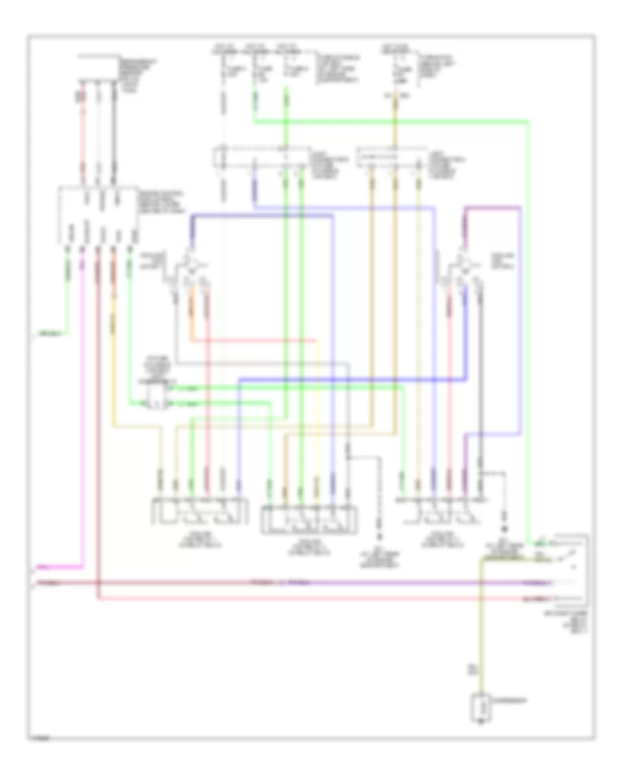
AIR CONDITIONING
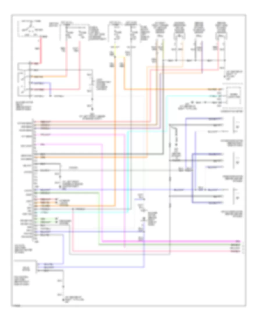
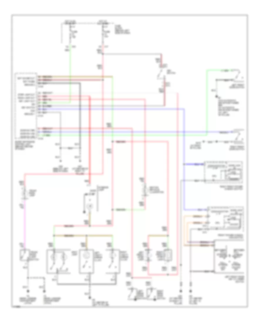
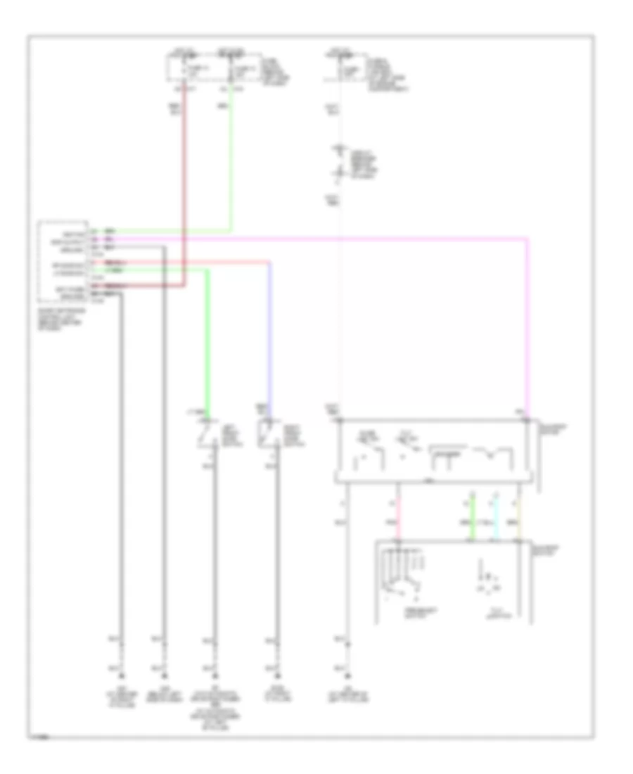
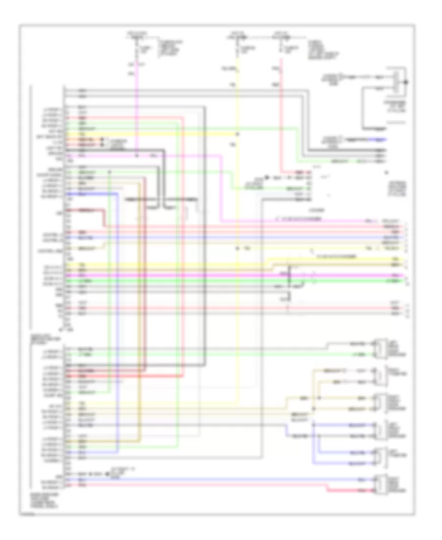
Automatic A/C Wiring Diagram, with Navigation (1 of 2) for Nissan Maxima GLE 2003
 https://portal-diagnostov.com/license.html
Automotive Electricians Portal FZCO
Automotive Electricians Portal FZCO
https://portal-diagnostov.com/license.html
https://portal-diagnostov.com/license.html
Automotive Electricians Portal FZCO
Automotive Electricians Portal FZCO
List of elements for Automatic A/C Wiring Diagram, with Navigation (1 of 2) for Nissan Maxima GLE 2003:
- (at center of right ``a" pillar) m87
- (at right front corner of vehicle) ambient sensor
- (behind center of dash) in-vehicle sensor
- (behind left side of dash)
- (behind right side of dash) intake sensor
- (on right defroster grille) sunload sensor
- 10k m17
- 15l m19
- A/c auto amplifier (behind lower center of dash)
- A/c av
- A/c clock
- Acc
- Air mix door motor (behind center of dash)
- Amb vdd
- Av-a/c
- Bat
- Blower motor (behind right side of dash)
- Blower motor relay (behind right side of dash)
- Board computer
- Clk
- Combination meter
- Comp
- Display & navi control unit (behind center of dash)
- E22 (at left front corner of engine compt)
- Ecm comp
- Fan control amplifier (behind right side of dash)
- Fan f/b
- Fan gate
- Fuse & fusible link box (at left side of engine compartment)
- Fuse 10a
- Fuse 15a
- Fuse block
- Gnd
- Hot at all times
- Hot in on
- Ign
- Ign 2
- Ign2
- Ignition switch
- Incar sens
- Intake door motor (behind right side of dash)
- Intake sens
- Joint connector 7 (in fuse & fusible link box)
- Lan-sig
- M169
- M170
- M171
- M33
- M34
- M87 (at center of right ``a" pillar)
- Mode door motor (behind center of dash)
- Off
- Or start
- Red
- Sens gnd
- Solid state
- Start
- Sun sens
- Vac
- Vactr
- W/t sens
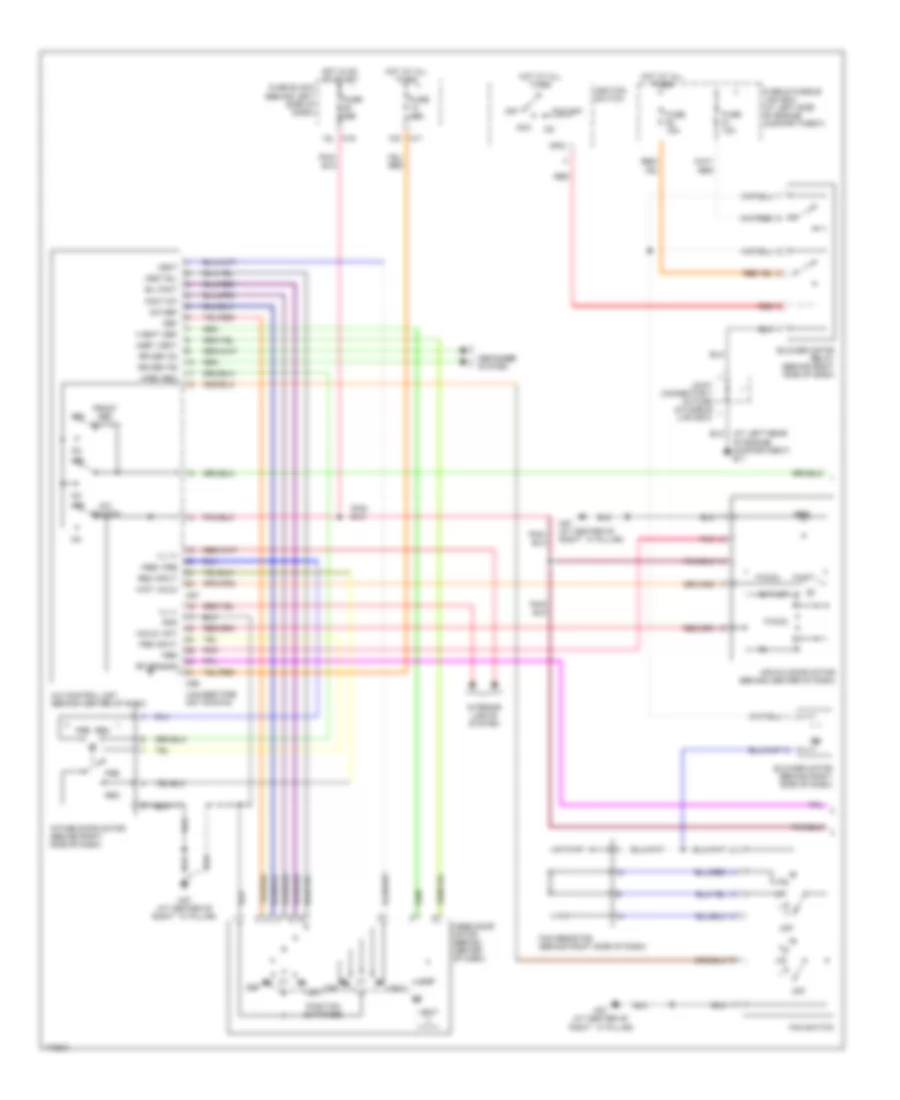
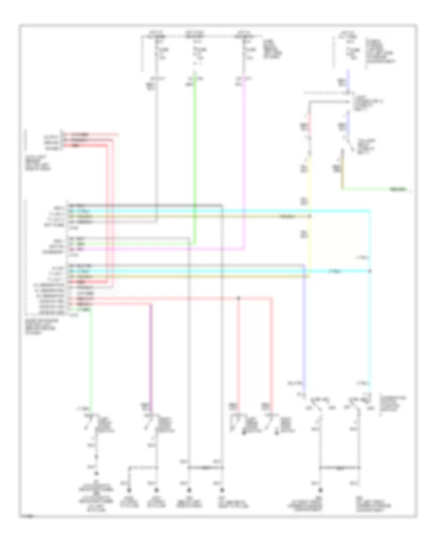
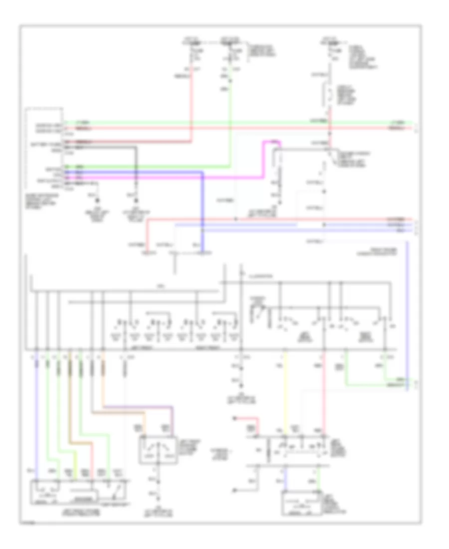
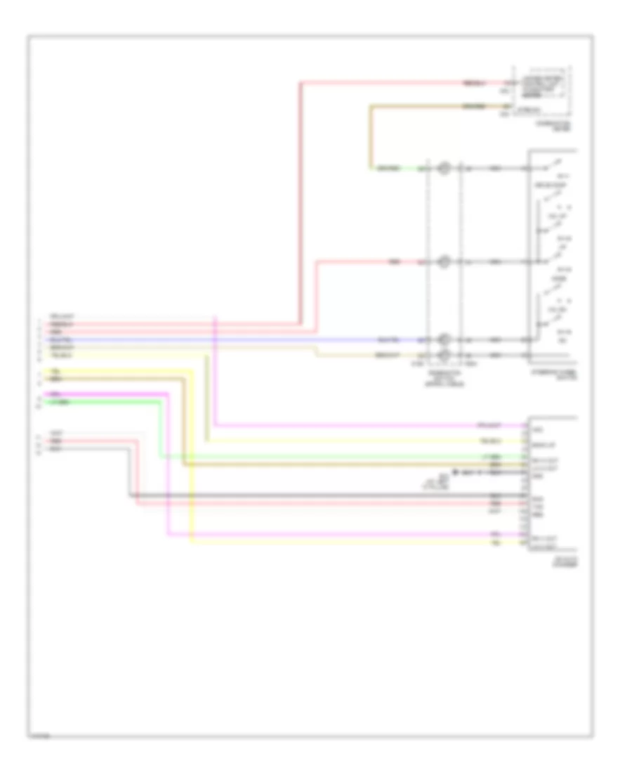
Automatic A/C Wiring Diagram, with Navigation (2 of 2) for Nissan Maxima GLE 2003
List of elements for Automatic A/C Wiring Diagram, with Navigation (2 of 2) for Nissan Maxima GLE 2003:
- (at left rear of engine compartment) e11
- (at left rear of engine compt) e11
- (in fuse & fusible link box) joint connector 10
- (on a/c liquid tank) refrigerant pressure sensor
- (on left rear of engine) engine coolant temperature sensor
- Acpdcut
- Acrly
- Air conditioner relay (in relay box 1)
- Arcon
- Avcc
- Compressor
- Cooling fan motor 1
- Cooling fan motor 2
- Cooling fan relay 1 (in relay box 2)
- Cooling fan relay 2 (in relay box 2)
- Cooling fan relay 3 (in relay box 2)
- E11 (at left rear of engine compartment)
- E83
- Engine control module (ecm) (behind lower center of dash)
- Fuse & fusible link box (at left side of engine compartment)
- Fuse 10a
- Fuse 15a
- Fuse block (behind left side of dash)
- Fuse g 40a
- Fuse h 40a
- Gnd-a
- Hi (+)
- Hi (-)
- Hot at all times
- Hot in on or start
- Joint connector (behind center of dash)
- Joint connector 8 (in fuse & fusible link box)
- Joint connector 9 (in fuse & fusible link box)
- Lo (+)
- Lo (-)
- Pdpres
- Red
- Rfrh
- Rfrl
- Tw0
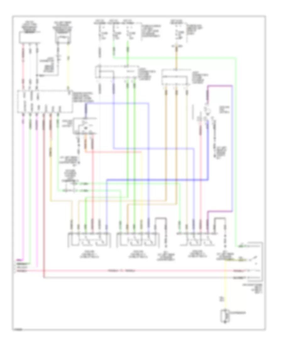
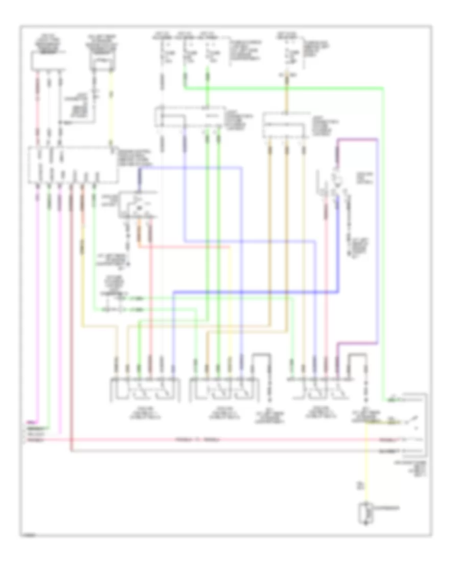
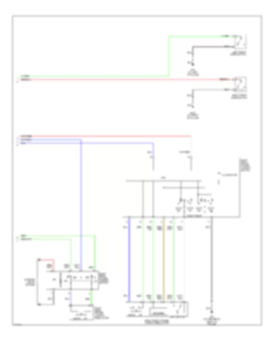
Automatic A/C Wiring Diagram, without Navigation (1 of 2) for Nissan Maxima GLE 2003
List of elements for Automatic A/C Wiring Diagram, without Navigation (1 of 2) for Nissan Maxima GLE 2003:
- (at center of right ``a" pillar) m87
- (at left front corner of engine compartment) e22
- (at right front corner of vehicle) ambient sensor
- (behind center of dash) in-vehicle sensor
- (behind left side of dash)
- (behind right side of dash) intake sensor
- (on right defroster grille) sunload sensor
- 10k m17
- 15l m19
- A/c auto amplifier (behind center of dash)
- Acc
- Air mix door motor (behind center of dash)
- Amb sens
- Amb vdd
- Bat
- Blower motor (behind right side of dash)
- Blower motor relay (behind right side of dash)
- Board computer
- Canada
- Cel/fht
- Combination meter
- Comp
- Defogger system
- E22 (at left front corner of engine compt)
- Ecm comp
- Fan control amplifier (behind right side of dash)
- Fan f/b
- Fan gate
- Fuse & fusible link box (at left side of engine compartment)
- Fuse 10a
- Fuse 15a
- Fuse block
- Gnd
- Hot at all times
- Hot in on
- Ign
- Ign 2
- Ign2
- Ignition switch
- Ill
- Incar sens
- Intake door motor (behind right side of dash)
- Intake sens
- Interior lights system
- Joint connector 7 (in fuse & fusible link box)
- Lan-sig
- Light
- M33
- M34
- M59
- M60
- M87 (at center of right ``a" pillar)
- Mode door motor (behind center of dash)
- Off
- Or start
- Red
- Rr def f/b
- Rr def on
- Sens gnd
- Solid state
- Start
- Sun sens
- Vactr
- W/t sens
Automatic A/C Wiring Diagram, without Navigation (2 of 2) for Nissan Maxima GLE 2003
List of elements for Automatic A/C Wiring Diagram, without Navigation (2 of 2) for Nissan Maxima GLE 2003:
- (at left rear of engine compartment) e11
- (at left rear of engine compt) e11
- (in fuse & fusible link box) joint connector 10
- (on a/c liquid tank) refrigerant pressure sensor
- (on left rear of engine) engine coolant temperature sensor
- Acpdcut
- Acrly
- Air conditioner relay (in relay box 1)
- Arcon
- Avcc
- Compressor
- Cooling fan motor 1
- Cooling fan motor 2
- Cooling fan relay 1 (in relay box 2)
- Cooling fan relay 2 (in relay box 2)
- Cooling fan relay 3 (in relay box 2)
- E11 (at left rear of engine compartment)
- E83
- Engine control module (ecm) (behind lower center of dash)
- Fuse & fusible link box (at left side of engine compartment)
- Fuse 10a
- Fuse 15a
- Fuse block (behind left side of dash)
- Fuse g 40a
- Fuse h 40a
- Gnd-a
- Hi (+)
- Hi (-)
- Hot at all times
- Hot in on or start
- Joint connector (behind center of dash)
- Joint connector 8 (in fuse & fusible link box)
- Joint connector 9 (in fuse & fusible link box)
- Lo (+)
- Lo (-)
- Pdpres
- Red
- Rfrh
- Rfrl
- Tw0
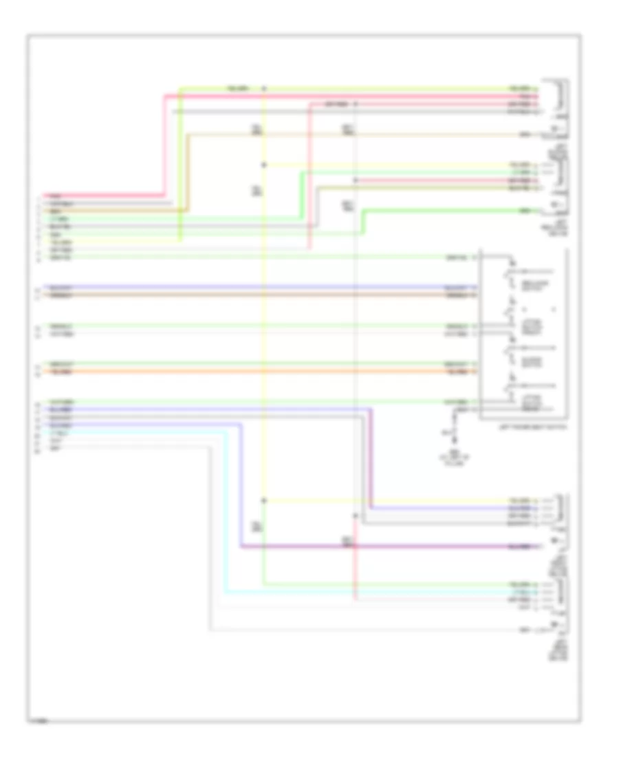
Manual A/C Wiring Diagram (1 of 2) for Nissan Maxima GLE 2003
List of elements for Manual A/C Wiring Diagram (1 of 2) for Nissan Maxima GLE 2003:
- (at left rear of engine compartment) e11
- (behind left side of dash)
- (unused pins not shown)
- +cold -hot
- +def -vent
- +fre -rec
- +hot -cold
- +rec -fre
- +vent -def
- 10k m17
- 15l m19
- A/c control unit (behind center of dash)
- A/c switch
- Acc
- Air mix door motor (behind center of dash)
- B/l foot
- Bl vent
- Blower motor (behind right side of dash)
- Blower motor relay (behind right side of dash)
- D/f def
- Def
- Defogger system
- F/cool
- F/hot
- Fan resistor (behind right side of dash)
- Fan switch
- Foot d/f
- Fre
- Fre input
- Front def switch
- Fuse & fusible link box (at left side of engine comparttment)
- Fuse 10a
- Fuse 15a
- Fuse block
- Gnd
- Hot at all times
- Hot in on or start
- Ign2
- Ignition switch
- Ill (+)
- Ill (-)
- Intake door motor (behind right side of dash)
- Interior lights system
- Joint connector 7 (in fuse & fusible link box)
- M56
- M57
- M87 (at center of right ``a" pillar)
- Mode door motor (behind center of dash)
- Off
- Pbr
- Pd sensor
- Pnk
- Position switches
- Rec
- Rec input
- Red
- Rr def f/b
- Rr def on
- Start
- Vent
- Vent b/l
Manual A/C Wiring Diagram (2 of 2) for Nissan Maxima GLE 2003
List of elements for Manual A/C Wiring Diagram (2 of 2) for Nissan Maxima GLE 2003:
- (in fuse & fusible link box) joint connector 10
- Acpdcut
- Acrly
- Air conditioner relay (in relay box 1)
- Arcon
- Avcc
- Compressor
- Cooling fan motor 1
- Cooling fan motor 2
- Cooling fan relay 1 (in relay box 2)
- Cooling fan relay 2 (in relay box 2)
- Cooling fan relay 3 (in relay box 2)
- E11 (at left rear of engine compartment)
- E83
- Engine control module (ecm) (behind lower center of dash)
- Fuse & fusible link box (at left side of engine compartment)
- Fuse 10a
- Fuse 15a
- Fuse block (behind left side of dash)
- Fuse g 40a
- Fuse h 40a
- Gnd-a
- Hi (+)
- Hi (-)
- Hot at all times
- Hot in on or start
- Joint connector 8 (in fuse & fusible link box)
- Joint connector 9 (in fuse & fusible link box)
- Lo (+)
- Lo (-)
- Pdpres
- Red
- Refrigerant pressure sensor (on a/c liquid tank)
- Rfrh
- Rfrl
ANTI-LOCK BRAKES
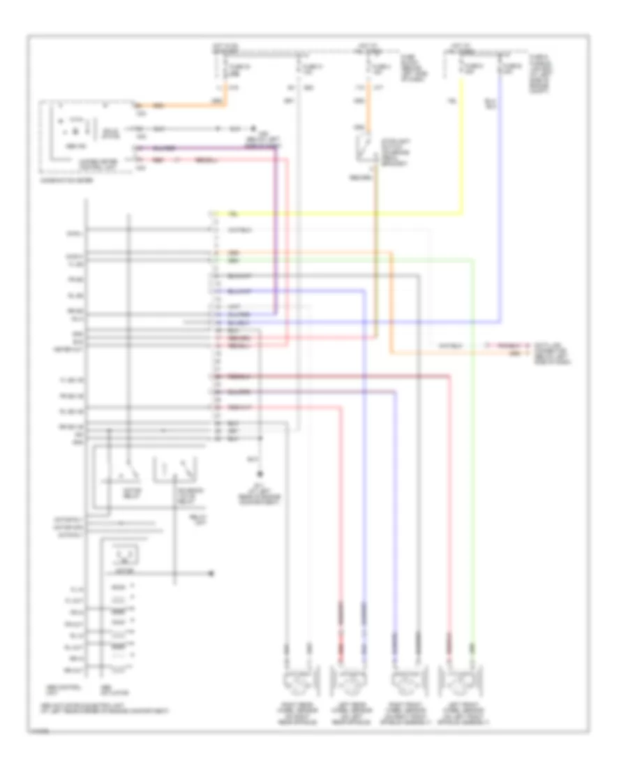
Anti-lock Brakes Wiring Diagram, A/T without Traction Control for Nissan Maxima GLE 2003
List of elements for Anti-lock Brakes Wiring Diagram, A/T without Traction Control for Nissan Maxima GLE 2003:
- (on left front spindle assembly)
- (on left rear spindle)
- (on right front spindle assembly)
- (on right rear spindle)
- 11k
- Abs actuator
- Abs actuator & electric unit (at left rear corner of engine compartment)
- Abs control unit
- Abs ind
- Actr rly
- Bls
- Combination meter
- Connector (below left side of dash)
- Data link
- Diag k
- Diag l
- E11 (at left rear of engine compartment)
- E83
- Fl in
- Fl out
- Fl ss
- Fl ss vb
- Fr in
- Fr out
- Fr ss
- Fr ss vb
- Fuse & fusible link box (at left side of engine compt)
- Fuse 2 15a
- Fuse 30 10a
- Fuse 31 10a
- Fuse block (behind left side of dash)
- Fuse d 40a
- Fuse e 40a
- Gnd
- Hot at all times
- Hot in on or start
- Ign
- Left front wheel sensor
- Left rear wheel sensor
- M17
- M19
- M25 (below left
- M32
- M33
- Meter out
- Motor
- Motor mon
- Motor relay
- Motor rly
- Red
- Relay unit
- Right front wheel sensor
- Right rear wheel sensor
- Rl in
- Rl out
- Rl ss
- Rl ss vb
- Rr in
- Rr out
- Rr ss
- Rr ss vb
- Side of dash)
- Sila
- Solenoid valve relay
- Solid state
- Stoplight switch (on brake pedal bracket)
- Unified meter control unit
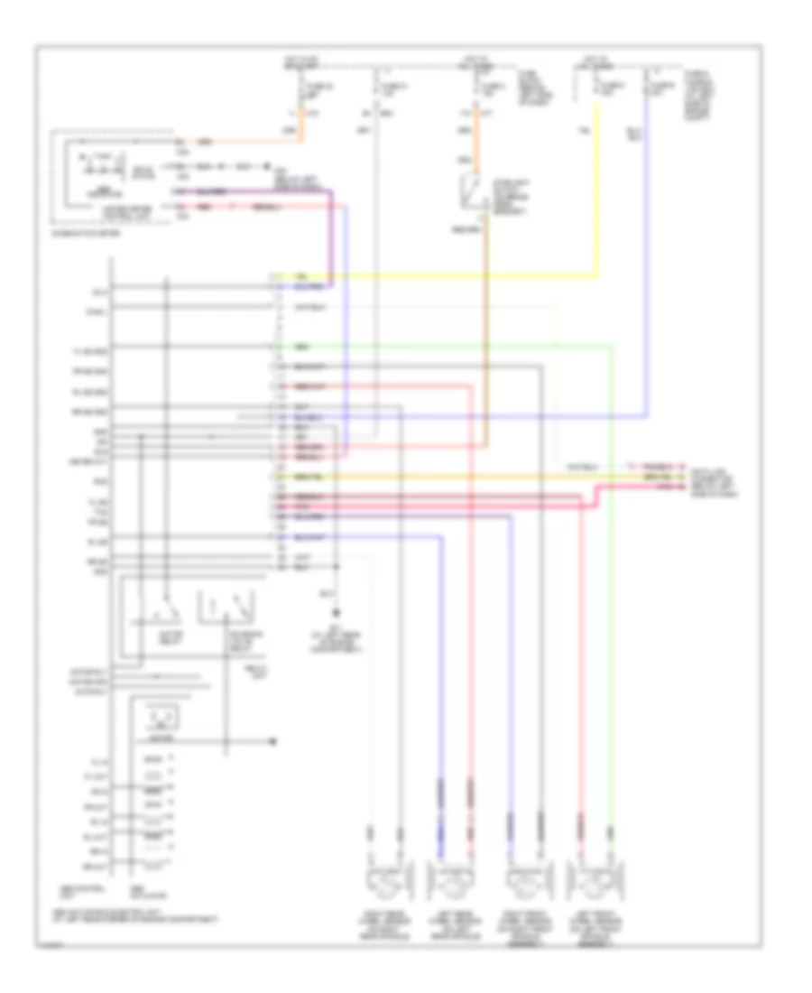
Anti-lock Brakes Wiring Diagram, M/T without Traction Control for Nissan Maxima GLE 2003
List of elements for Anti-lock Brakes Wiring Diagram, M/T without Traction Control for Nissan Maxima GLE 2003:
- 11k
- Abs actuator
- Abs actuator & electric unit (at left rear corner of engine compartment)
- Abs control unit
- Abs indicator
- Actr rly
- Bls
- Combination meter
- Data link connector (below left
- Diag l
- E11 (at left rear of engine compartment)
- E83
- Fl in
- Fl out
- Fl ss
- Fl ss gnd
- Fr in
- Fr out
- Fr ss
- Fr ss gnd
- Fuse & fusible link box (at left side of engine compt)
- Fuse 2 15a
- Fuse 30 10a
- Fuse 31 10a
- Fuse block (behind left side of dash)
- Fuse d 40a
- Fuse e 40a
- Gnd
- Hot at all times
- Hot in on or start
- Ign
- Left front wheel sensor (on left front spindle assembly)
- Left rear wheel sensor (on left rear spindle)
- M17
- M19
- M25 (below left side of dash)
- M32
- M33
- Meter out
- Motor
- Motor mon
- Motor relay
- Motor rly
- Pnk
- Red
- Relay unit
- Right front wheel sensor (on right front spindle assembly)
- Right rear wheel sensor (on right rear spindle)
- Rl in
- Rl out
- Rl ss
- Rl ss gnd
- Rr in
- Rr out
- Rr ss
- Rr ss gnd
- Rxd
- Side of dash)
- Sila
- Solenoid valve relay
- Solid state
- Stoplight switch (on brake pedal bracket)
- Txd
- Unified meter control unit
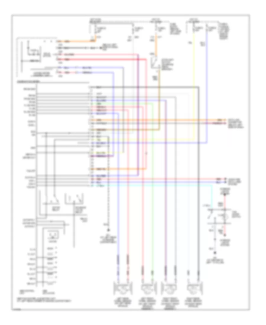
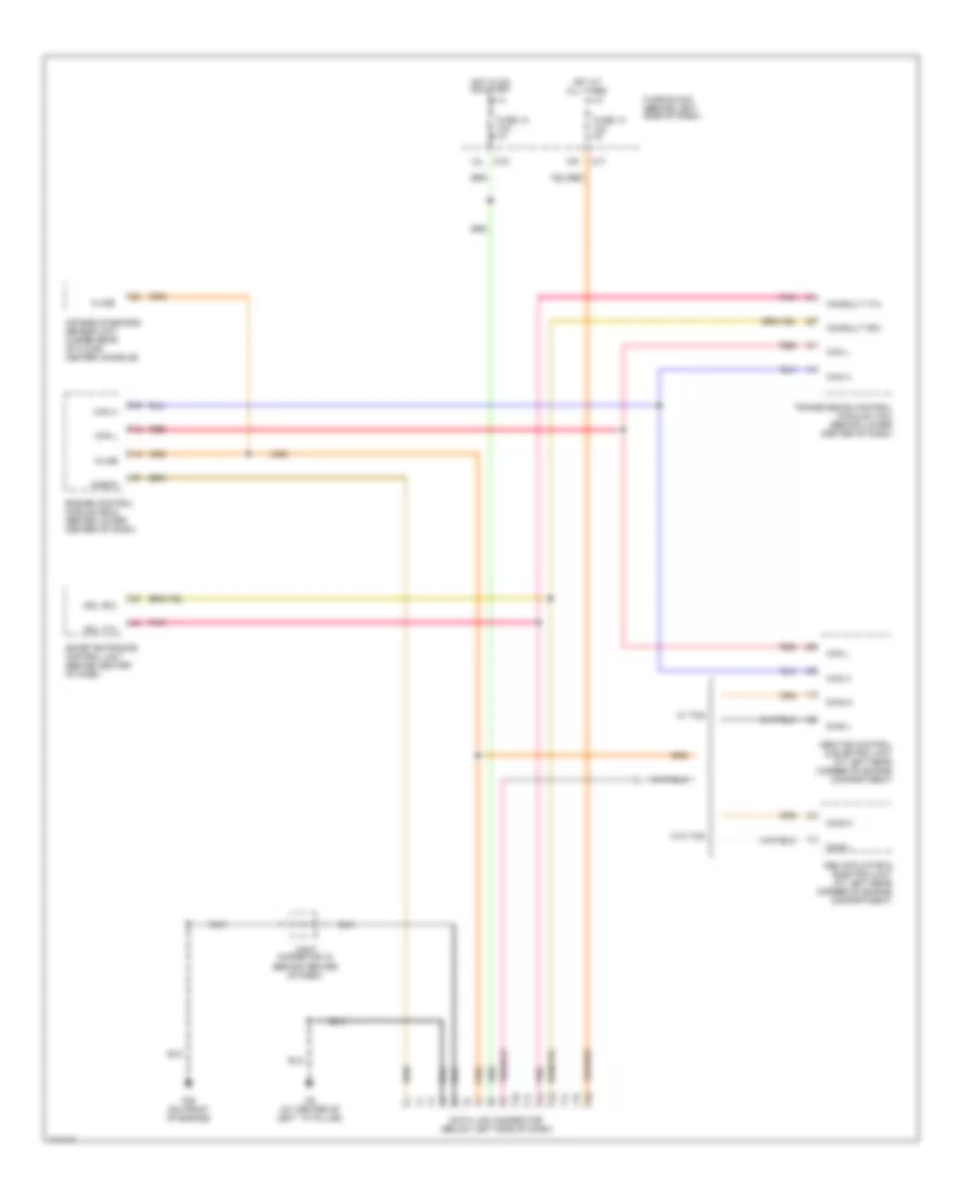
Anti-lock Brakes Wiring Diagram, with Traction Control for Nissan Maxima GLE 2003
List of elements for Anti-lock Brakes Wiring Diagram, with Traction Control for Nissan Maxima GLE 2003:
- (below left side of dash) m25
- (on left front spindle assembly)
- (on right front spindle assembly)
- (on right rear spindle)
- 11k
- Abs actuator
- Abs control unit
- Abs ind
- Abs sila
- Abs/tcs control & electric unit (at left rear corner of engine compartment)
- Actr rly
- Bls
- Can h
- Can l
- Combination meter
- Computer data lines system
- Connector (below left side of dash)
- Data link
- Diag k
- Diag l
- E11 (at left rear of engine compartment)
- E83
- Fl in
- Fl out
- Fl ss
- Fl ss gnd
- Fr in
- Fr out
- Fr ss
- Fr ss gnd
- Fuse & fusible link box (at left side of engine compt)
- Fuse 2 15a
- Fuse 30 10a
- Fuse 31 10a
- Fuse block (behind left side of dash)
- Fuse d 40a
- Fuse e 40a
- Gnd
- Hot at all times
- Hot in on or start
- Ign
- Illum
- Interior lights system
- Left front wheel sensor
- Left rear wheel sensor (on left rear spindle)
- M17
- M19
- M32
- M33
- M34
- M9 (at center of left ``a" pillar)
- Meter out
- Motor
- Motor mon
- Motor relay
- Motor rly
- Red
- Relay unit
- Right front wheel sensor
- Right rear wheel sensor
- Rl in
- Rl out
- Rl ss
- Rl ss gnd
- Rr in
- Rr out
- Rr ss
- Rr ss gnd
- Slip sila
- Solenoid valve relay
- Solid state
- Stoplight switch (on brake pedal bracket)
- Tcs off
- Tcs on/off switch
- Tcs sw
- Unified meter control unit
ANTI-THEFT
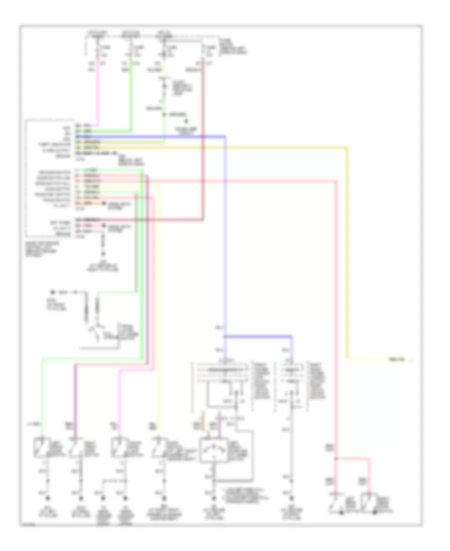
Anti-theft Wiring Diagram (1 of 2) for Nissan Maxima GLE 2003
List of elements for Anti-theft Wiring Diagram (1 of 2) for Nissan Maxima GLE 2003:
- (at right "c" pillar)
- 10k
- 12k
- 12l
- Acc
- Alarm output
- B106
- B12 (at left "c" pillar)
- B127 (at right "b" pillar)
- Bat (fuse)
- Clock (security indicator lamp)
- Com
- Com i/f
- Communication i/f
- Cpu
- D10
- D13
- Door switch (all)
- Door switch (as)
- Dr door switch
- E53 (at right front corner of engine compartment)
- Front power window main switch (door lock & unlock switch)
- Full stroke
- Fuse 10a
- Fuse block (behind left side of dash)
- Ground
- H/l out 1
- H/l out 2
- Headlights system
- Hood switch
- Hood switch (at left front corner of engine compt)
- Hot at all times
- Hot in acc or on
- Hot in on or start
- Ign
- Immobilizer circuit
- Left front door key cylinder switch
- Left front door switch
- Left rear door switch
- Lock-between full
- M143
- M144
- M145
- M17
- M19
- M25 (below left side of dash)
- M87 (at center of right "a" pillar)
- M9 (at center of left "a" pillar)
- Pnk
- Right front door switch
- Right front power window switch (door lock & unlock switch)
- Right rear door switch
- Smart entrance control unit (behind center of dash)
- Stroke & normal
- Stroke & normal unlock-between full
- T6 (near luggage compt latch)
- T8 (near luggage compt latch)
- Theft indicator
- Trunk lid key cylinder switch
- Trunk key switch
- Trunk room lamp switch
- Trunk switch
- Unlk
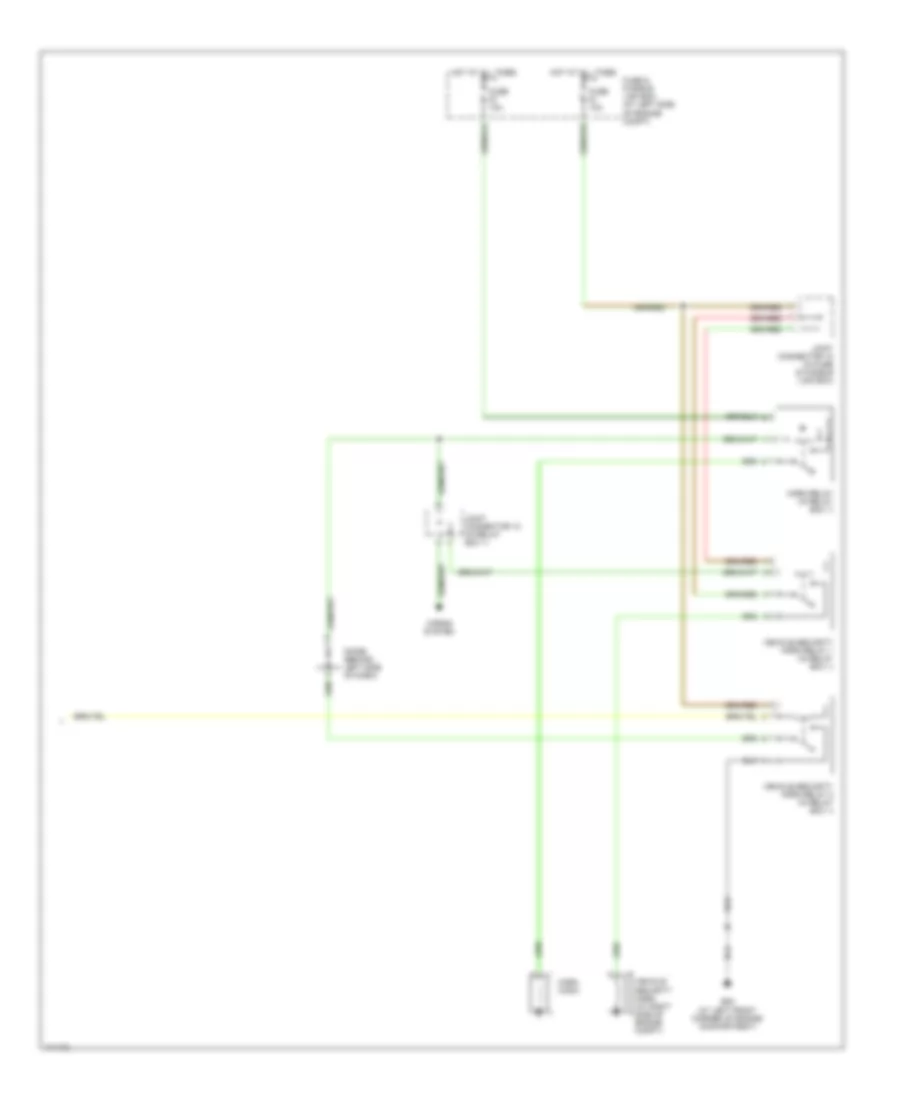
Anti-theft Wiring Diagram (2 of 2) for Nissan Maxima GLE 2003
List of elements for Anti-theft Wiring Diagram (2 of 2) for Nissan Maxima GLE 2003:
- Diode (behind left side of dash)
- E22 (at left front corner of engine compartment)
- Fuse & fusible link box (at left side of engine compt)
- Fuse 10a
- Horn (high)
- Horn relay (in relay box 1)
- Horns system
- Hot at all times
- Joint connector 10 (in fuse & fusible link box)
- Joint connector 12 (in relay box 1)
- Vehicle security horn (at right side of engine compt)
- Vehicle security horn relay 1 (in relay box 1)
- Vehicle security horn relay 2 (in relay box 1)
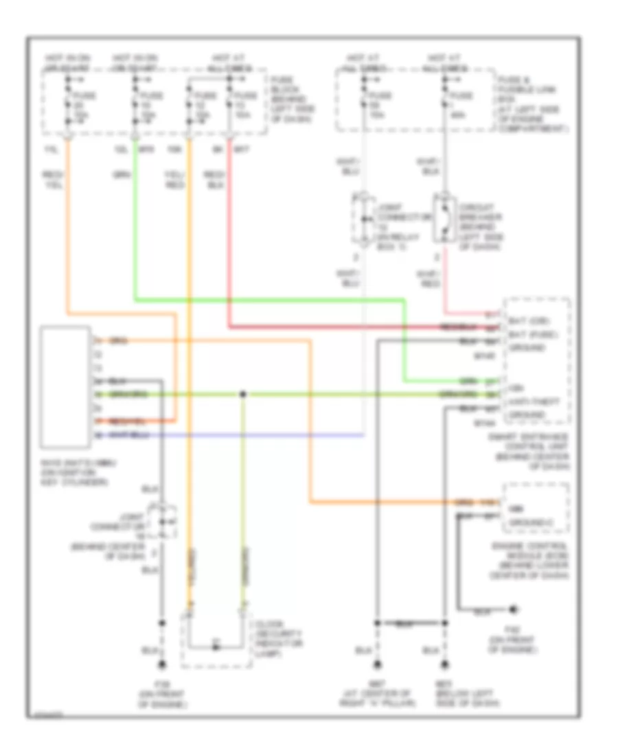
Immobilizer Wiring Diagram for Nissan Maxima GLE 2003
List of elements for Immobilizer Wiring Diagram for Nissan Maxima GLE 2003:
- 10k
- 11l
- 12l
- Anti-theft
- Bat (c/b)
- Bat (fuse)
- Circuit breaker (behind left side of dash)
- Clock (security indicator lamp)
- Engine control module (ecm) (behind lower center of dash)
- F39 (on front of engine)
- F42 (on front of engine)
- Fuse & fusible link box (at left side of engine compartment)
- Fuse 10a
- Fuse 15a
- Fuse block (behind left side of dash)
- Fuse i 40a
- Ground
- Ground-c
- Hot at all times
- Hot in on or start
- Ign
- Imm
- Joint connector (behind center of dash)
- Joint connector (in relay box 1)
- M144
- M145
- M17
- M19
- M25 (below left side of dash)
- M87 (at center of right "a" pillar)
- Nvis (nats) immu (on ignition key cylinder)
- Smart entrance control unit (behind center of dash)
BODY CONTROL MODULES
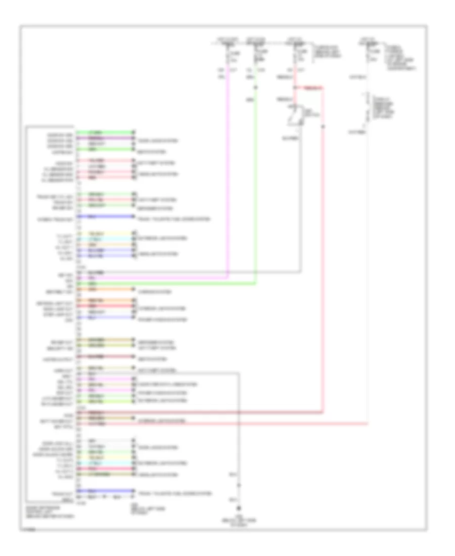
Body Control Modules Wiring Diagram for Nissan Maxima GLE 2003
List of elements for Body Control Modules Wiring Diagram for Nissan Maxima GLE 2003:
- 12k
- 12l
- A/l sensor gnd
- A/l sensor pwr
- A/l sensor sig
- A/l sw
- Acc
- Anti-theft system
- Bat (ptc)
- Batt saver out
- Circuit breaker (behind left side of dash)
- Com
- Computer data lines system
- Ddl (rx)
- Ddl (tx)
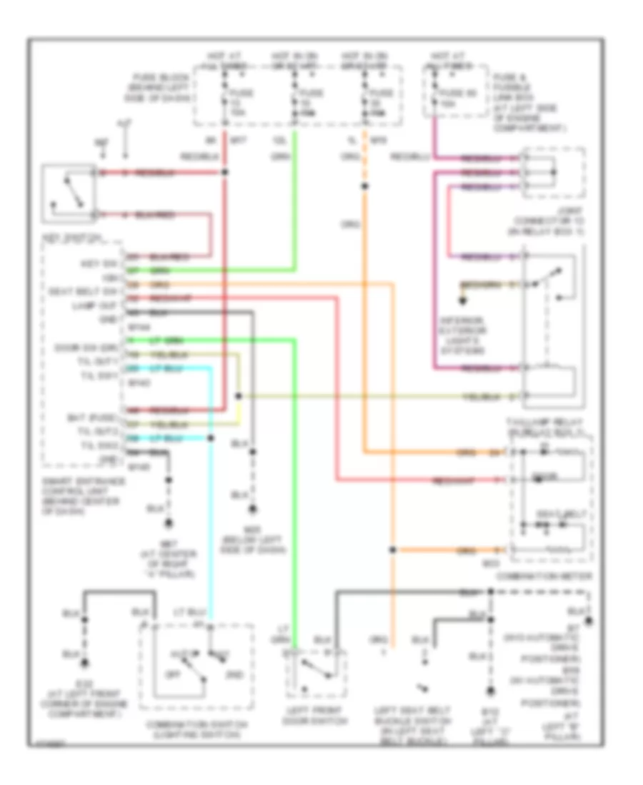
- Defogger system
- Door lock (all)
- Door locks system
- Door sw (as)
- Door sw (dr)
- Door sw (rr)
- Door unlock (as,rr)
- Door unlock (dr)
- Exterior lights system
- Fuse & fusible link box (at left side of engine compartment)
- Fuse 10a
- Fuse block (behind left side of dash)
- Fuse i 40a
- Gnd 1
- Gnd 2
- H/l out 1
- H/l out 2
- H/l sw1
- H/l sw2
- H/strg output
- H/strg sw
- Headlights system
- Hood sw
- Horn out
- Hot at all times
- Hot in acc or on
- Hot in on or start
- Ign
- Interia trunk sw
- Interior lights system
- Key sw
- Key switch
- Keyring light out
- Lh flasher out
- M143
- M144
- M145
- M17
- M19
- M25 (below left side of dash)
- Pnk
- Power windows system
- Pwr
- Rap out
- Red
- Rh flasher out
- Room lamp out
- Rr def out
- Rr def sw
- Seatbelt sw
- Seats system
- Security ind
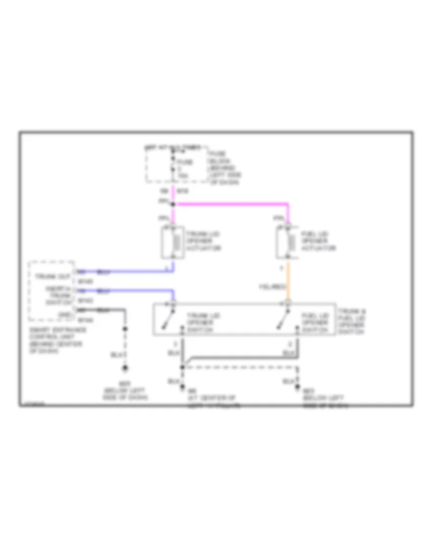
- Smart entrance control unit (behind center of dash)
- Step lamp out
- T/l out1
- T/l out2
- T/l sw 2
- T/l sw1
- Trunk key cyl sw
- Trunk out
- Trunk sw
- Trunk, tailgate, fuel doors system
- Warning system
COMPUTER DATA LINES
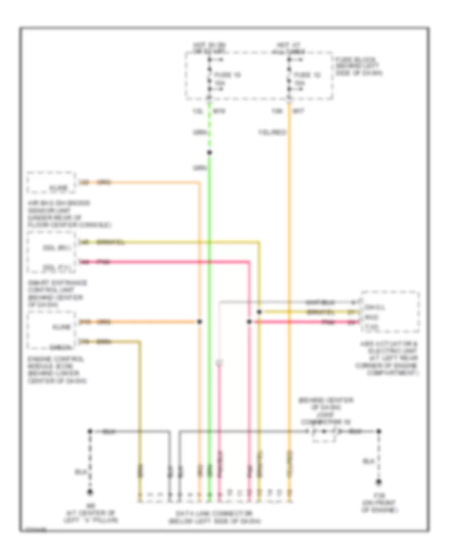
Computer Data Lines Wiring Diagram, A/T for Nissan Maxima GLE 2003
List of elements for Computer Data Lines Wiring Diagram, A/T for Nissan Maxima GLE 2003:
- 10k
- 12l
- Abs actuator & electric unit (at left rear corner of engine compartment)
- Abs/tcs control & electric unit (at left rear corner of engine compartment)
- Air bag diagnosis sensor unit (under rear of floor center console)
- Can h
- Can l
- Check
- Consult (rx)
- Consult (tx)
- Data link connector (below left side of dash)
- Ddl (rx)
- Ddl (tx)
- Diag k
- Diag l
- Engine control module (ecm) (behind lower center of dash)
- F39 (on front of engine)
- Fuse 10 10a
- Fuse 12 10a
- Fuse block (behind left side of dash)
- Hot at all times
- Hot in on or start
- Joint connetor 18 (behind center of dash)
- Kline
- M17
- M19
- M9 (at center of left ``a" pillar)
- Pnk
- Red
- Smart entrance control unit (behind center of dash)
- Transmission control module (tcm) (behind lower center of dash)
- W/ tcs
- W/o tcs
Computer Data Lines Wiring Diagram, M/T for Nissan Maxima GLE 2003
List of elements for Computer Data Lines Wiring Diagram, M/T for Nissan Maxima GLE 2003:
- (behind center of dash) joint connector 18
- 10k
- 12l
- Abs actuator & electric unit (at left rear corner of engine compartment)
- Air bag diagnosis sensor unit (under rear of floor center console)
- Check
- Data link connector (below left side of dash)
- Ddl (rx)
- Ddl (tx)
- Diag l
- Engine control module (ecm) (behind lower center of dash)
- F39 (on front of engine)
- Fuse 10 10a
- Fuse 12 10a
- Fuse block (behind left side of dash)
- Hot at all times
- Hot in on or start
- Kline
- M17
- M19
- M9 (at center of left ``a" pillar)
- Pnk
- Rxd
- Smart entrance control unit (behind center of dash)
- Txd
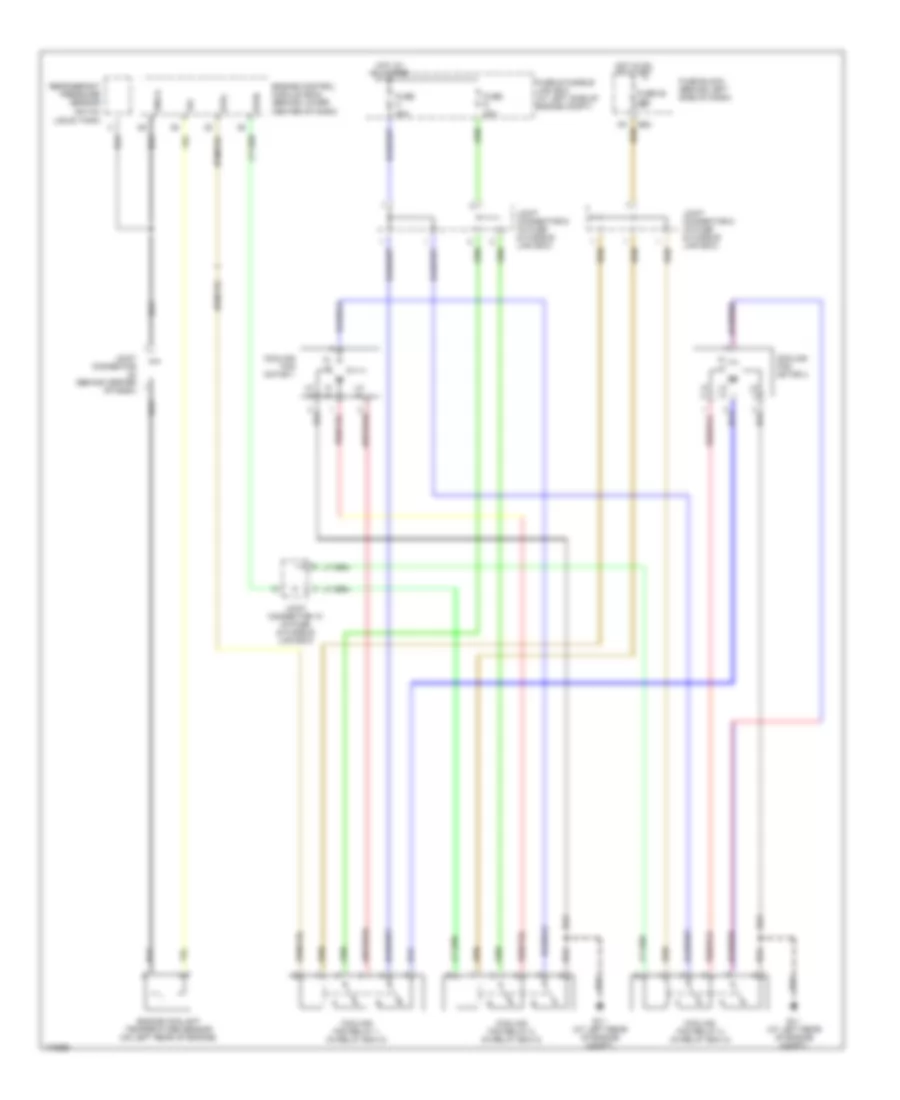
COOLING FAN
Cooling Fan Wiring Diagram for Nissan Maxima GLE 2003
List of elements for Cooling Fan Wiring Diagram for Nissan Maxima GLE 2003:
- Cooling fan motor 1
- Cooling fan motor 2
- Cooling fan relay 1 (in relay box 2)
- Cooling fan relay 2 (in relay box 2)
- Cooling fan relay 3 (in relay box 2)
- E11 (at left rear of engine compt)
- E83
- Engine control module (ecm) (behind lower center of dash)
- Engine coolant temperature sensor (on left rear of engine)
- Fuse & fusible link box (at left side of engine compt)
- Fuse 20 15a
- Fuse block (behind left side of dash)
- Fuse g 40a
- Fuse h 40a
- Gnd-a
- Hi (+)
- Hi (-)
- Hot at all times
- Hot in on or start
- Joint connector (behind center of dash)
- Joint connector 10 (in fuse & fusible link box)
- Joint connector 8 (in fuse & fusible link box)
- Joint connector 9 (in fuse & fusible link box)
- Lo (+)
- Lo (-)
- Refrigerant pressure sensor (on a/c liquid tank)
- Rfrh
- Rfrl
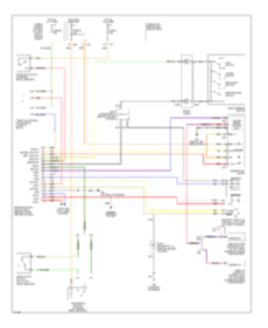
CRUISE CONTROL
Cruise Control Wiring Diagram for Nissan Maxima GLE 2003
List of elements for Cruise Control Wiring Diagram for Nissan Maxima GLE 2003:
- 11k
- A/t
- A/t m/t
- Abs actuator & electric unit (at left rear corner of engine compartment)
- Abs/tcs control & electric unit (at left rear corner of engine compartment)
- Ascd brake switch (on brake pedal bracket)
- Ascd clutch switch (on clutch pedal bracket)
- Ascd steering switch
- Ascd sw
- Avcc
- Bnc sw
- Brake sw
- Can-h
- Can-l
- Cancel switch
- Close
- Combination meter
- Computer data lines system
- Cruise
- Cruise lamp out
- E83
- Electric throttle control actuator (on throttle body)
- Engine control module (ecm) (behind lower center of dash)
- Engine controls system
- F39 (on front of engine)
- Fuse & fusible link box (at left side of engine compt)
- Fuse 2 15a
- Fuse 30 10a
- Fuse 63 15a
- Fuse block (behind left side of dash)
- Gnd
- Gnd-a
- Hot at all times
- Hot in on or start
- Joint connector 20 (behind center of dash)
- Joint connectot 18 (behind center of dash)
- M/t
- M158
- M17
- M19
- M25 (below left side of dash)
- M32
- M33
- M34
- M644
- Main switch
- Meter out
- Motor 1
- Motor 2
- Motrly
- Nca
- Open
- Red
- Resume/accel switch
- Sensor 1
- Sensor 2
- Set
- Set lamp out
- Set/coast switch
- Spiral cable
- Stoplight switch (on brake pedal bracket)
- Throttle control motor relay (in relay box 2)
- Tps1
- Tps2
- Unified meter control unit
- Vmot
- Vsp-8
- W/ tcs
- W/o tcs
DEFOGGERS
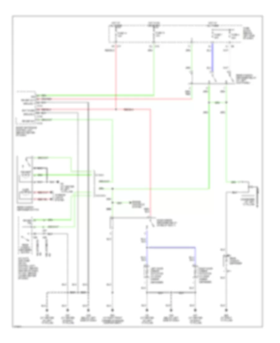
Defoggers Wiring Diagram for Nissan Maxima GLE 2003
List of elements for Defoggers Wiring Diagram for Nissan Maxima GLE 2003:
- (w/ door
- 10a
- 12l m19
- 20a
- 20a
- 8k m17
- A/c
- A/c auto amplifier (or a/c control unit) (w/o nav: behind center of dash) (w/ nav: behind lower center of dash)
- B11
- B62 (at right ``c" pillar)
- B81
- Bat (fuse)
- Condenser (at left ``c" pillar)
- Defogger)
- Door mirror defogger relay (in relay box 1)
- E53 (at right front corner of engine compartment)
- Engine controls system
- Fuse 10
- Fuse 13
- Fuse 4
- Fuse 7
- Fuse block (behind left side of dash)
- Ground 1
- Ground 2
- Hot at all times
- Hot in on or start
- Ign
- Illum
- Ind lamp
- Interior lights system
- Left door mirror actuator
- M143
- M144
- M145
- M25 (below left side of dash)
- M56
- M57
- M60
- M87 (at center of right ``a" pillar)
- M9 (at center of left ``a" pillar)
- M9 (at center of left ``a" pillar)
- Mirror
- Nca
- Rear window defogger
- Rear window defogger relay (at left kick panel)
- Rear window defogger switch
- Right door mirror actuator (w/ door
- Rr def f/b
- Rr def out
- Rr def sw
- Smart entrance control unit (behind center of dash)
- W/ automatic
- W/ navi
- W/o automatic
- W/o navi
ENGINE PERFORMANCE
3.5L
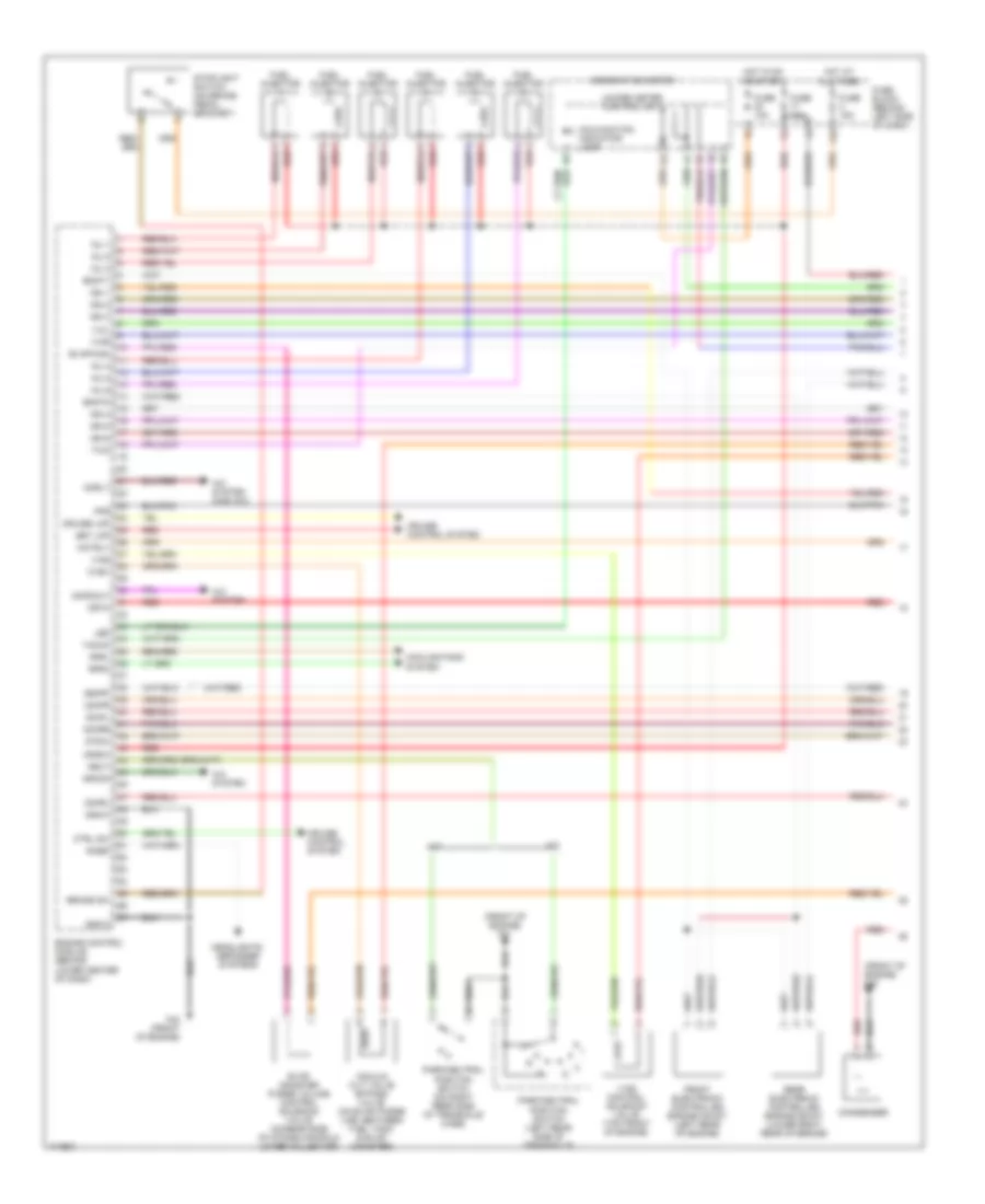
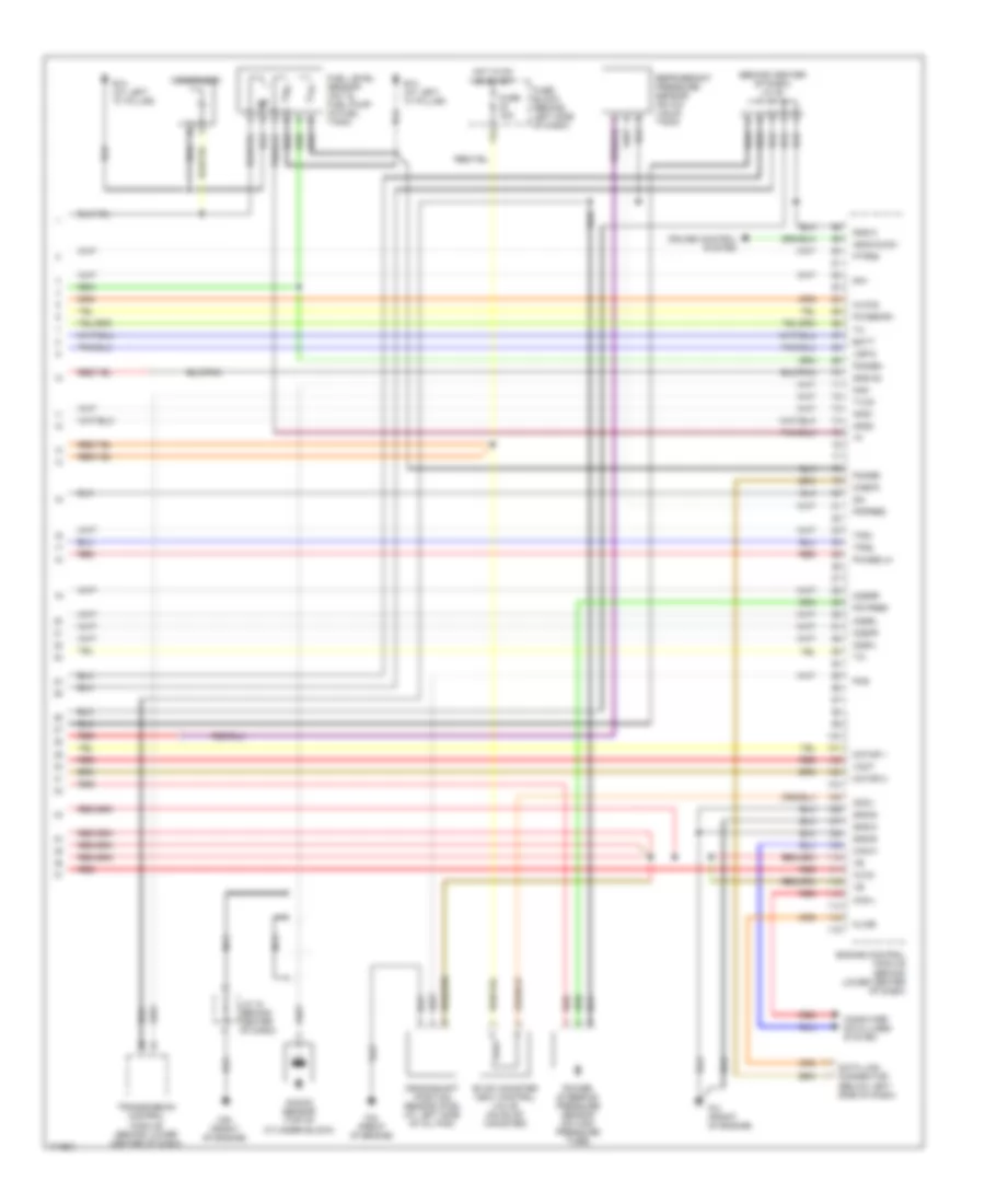
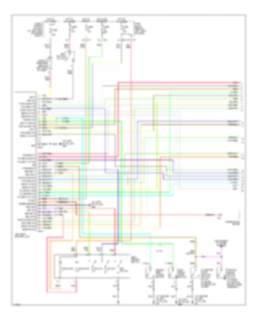
3.5L, Engine Performance Wiring Diagram (1 of 4) for Nissan Maxima GLE 2003
List of elements for 3.5L, Engine Performance Wiring Diagram (1 of 4) for Nissan Maxima GLE 2003:
- (front of engine) f40
- (front of engine) f41
- 11k
- A/c system
- A/c system (man a/c)
- A/t
- Acpdcut
- Acrly
- Arcon
- Brake sw
- Combination meter
- Condenser
- Cooling fans system
- Crtn
- Cruise control system
- Cruise lmp
- Ctrl sw
- Cvbv
- Emnt1
- Emnt2
- Engine control module (behind lower center of dash)
- Evap canister purge volume control solenoid valve (on rear side of intake manifold lower collector)
- Evap-nam
- F42 (front of engine)
- Fpr
- Front electronic controlled engine mount (left rear of engine)
- Fuel injector
- Fuse 10a
- Fuse 15a
- Fuse block (behind left side of dash)
- Gnd-c
- Headlights, defogger systems
- Hot at all times
- Hot in on or start
- Ign 1
- Ign 2
- Ign 3
- Ign 4
- Ign 5
- Ign 6
- Ignsw
- Inj 1
- Inj 2
- Inj 3
- Inj 4
- Inj 5
- Inj 6
- Ivcl
- Ivcr
- Led
- M/t
- Malfunction indicator lamp
- Motrly
- Neut
- O2hfl
- O2hfr
- O2hrl
- O2hrr
- Park/neutral position switch (left rear side of transaxle)
- Park/neutral position switch (on right rear side of transaxle case)
- R/def
- Rear electronic controlled engine mount (lower right rear of engine)
- Red
- Rfrh
- Rfrl
- Set lmp
- Ssoff
- Stoplight switch (on brake pedal bracket)
- Stsw
- Tacho
- Two
- Unified meter control unit
- Vacuum cut valve bypass valve (on evap purge line, between fuel tank & evap canister)
- Vias
- Vias control solenoid valve (top front of engine)
3.5L, Engine Performance Wiring Diagram (2 of 4) for Nissan Maxima GLE 2003
List of elements for 3.5L, Engine Performance Wiring Diagram (2 of 4) for Nissan Maxima GLE 2003:
- Accelerator pedal position (app) sensor 1
- Accelerator pedal position (app) sensor 2
- Ecm relay
- Electric throttle control actuator (on throttle body)
- F39 (front of engine)
- F40 (front of engine)
- F64
- Fuse & fusible link box (left side of engine compt)
- Fuse 10a
- Fuse 15a
- Fuse block (behind left side of dash)
- Hot at all times
- Hot in start
- Ignition coil 1 (w/ power transistor)
- Ignition coil 2 (w/ power transistor)
- Ignition coil 3 (w/ power transistor)
- Ignition coil 4 (w/ power transistor)
- Ignition coil 5 (w/ power transistor)
- Ignition coil 6 (w/ power transistor)
- J/c 12 (in relay box 1)
- J/c 19
- M159
- Nca
- Plug spark
- Red
- Relay box 2 (left front corner of engine compt)
- Spark plug
- Throttle control motor
- Throttle control motor relay
- Throttle position (tp) sensor 1
- Throttle position (tp) sensor 2
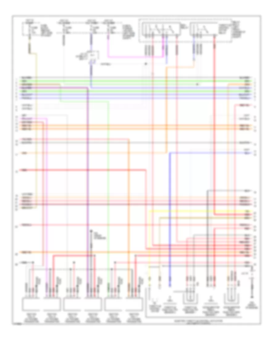
3.5L, Engine Performance Wiring Diagram (3 of 4) for Nissan Maxima GLE 2003
List of elements for 3.5L, Engine Performance Wiring Diagram (3 of 4) for Nissan Maxima GLE 2003:
- 13l
- Camshaft position sensor (phase) (bank 1) (rear of right cyl head)
- Camshaft position sensor (phase) (bank 2) (rear of left cyl head)
- Engine coolant temperature sensor (left rear of engine)
- Evap control system pressure sensor (under vehicle, near evap canister)
- F39 (front of engine)
- F42 (front of engine)
- Fuel pump relay (behind left kick panel)
- Fuse 15a
- Fuse block (behind left side of dash)
- Heated oxygen sensor 1 (bank 1) (on right exhaust manifold)
- Heated oxygen sensor 1 (bank 2) (on left exhaust manifold)
- Heated oxygen sensor 2 (bank 1) (on front exhaust tube assembly)
- Heated oxygen sensor 2 (bank 2) (on left twc manifold)
- Hot in on or start
- Intake valve timing control solenoid valve (bank 1) (top front of right cylinder head)
- Intake valve timing control solenoid valve (bank 2) (top front of left cylinder head)
- J/c
- Mass airflow (maf) sensor (intake air temp sensor) (on intake air duct)
- Red
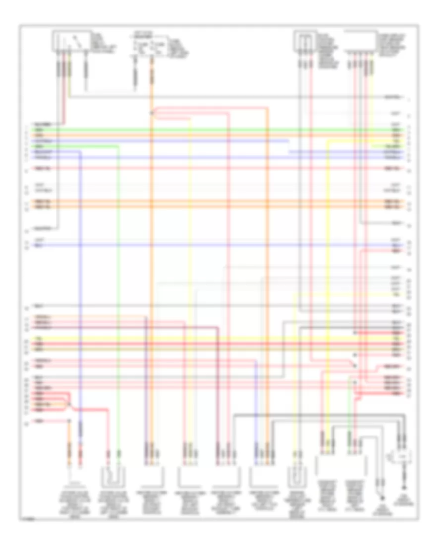
3.5L, Engine Performance Wiring Diagram (4 of 4) for Nissan Maxima GLE 2003
List of elements for 3.5L, Engine Performance Wiring Diagram (4 of 4) for Nissan Maxima GLE 2003:
- (behind center of dash) j/c 20
- 11l
- Aps1
- Aps2
- Ascd b sw
- Avcc
- Avcc2
- B13 (at left "c" pillar)
- Batt
- Can-h
- Can-l
- Cdcv
- Check
- Computer data lines system
- Condenser
- Crankshaft position sensor (pos) (at left side of oil pan)
- Cruise control system
- Data link connector (below left side of dash)
- Engine control module (behind lower center of dash)
- Evap canister vent control valve (on evap canister)
- F39 (front of engine)
- F41 (front of engine)
- F42 (front of engine)
- Fgage+
- Fgage-
- Ftprs
- Fuel level sensor unit & fuel pump (in fuel tank)
- Fuse 15a
- Fuse block (behind left side of dash)
- Gnd-a
- Gnd-a2
- Gnd-e
- Gnd-m
- Hot in on or start
- J/c 18 (behind center of dash)
- Kline
- Knk
- Knock sensor (top of cylinder block)
- Motor 1
- Motor 2
- Nca
- O2sfl
- O2sfr
- O2srl
- O2srr
- Pdpres
- Phase-lh
- Phase-rh
- Pos
- Power steering pressure sensor (on high pressure tube)
- Ps pres
- Qa+
- Qa-
- Red
- Refrigerant pressure sensor (on a/c liquid tank)
- Tps1
- Tps2
- Transmission control module (behind lower center of dash)
- Tvcc
- Vmot
- Vsp-8
EXTERIOR LIGHTS
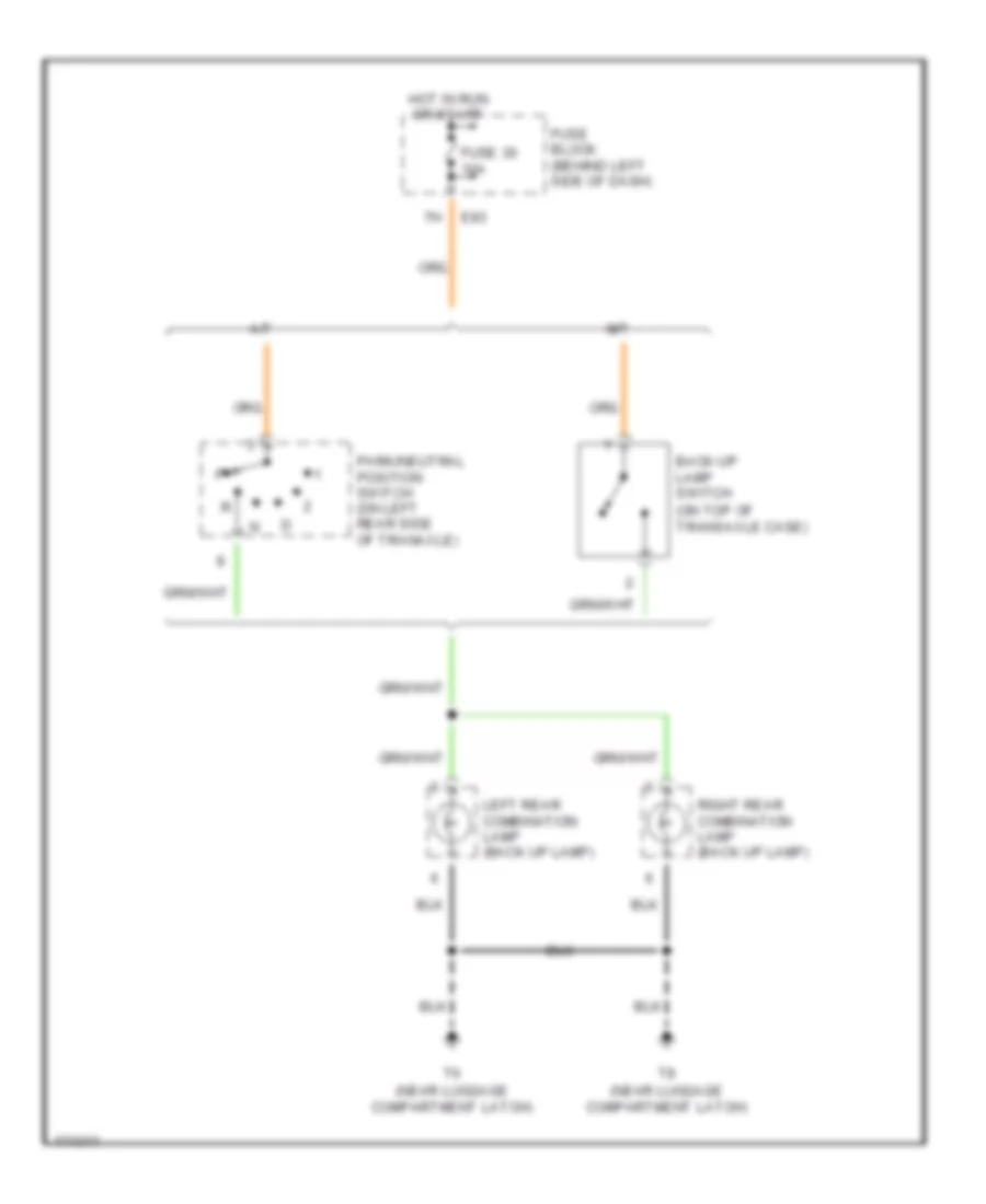
Back-up Lamps Wiring Diagram for Nissan Maxima GLE 2003
List of elements for Back-up Lamps Wiring Diagram for Nissan Maxima GLE 2003:
- (near luggage compartment latch)
- (on top of transaxle case)
- A/t
- Back-up lamp switch
- E83
- Fuse 30 10a
- Fuse block (behind left side of dash)
- Hot in run or start
- Left rear combination lamp (back up lamp)
- M/t
- Park/neutral position switch (on left rear side of tranaxle)
- Right rear combination lamp (back up lamp)
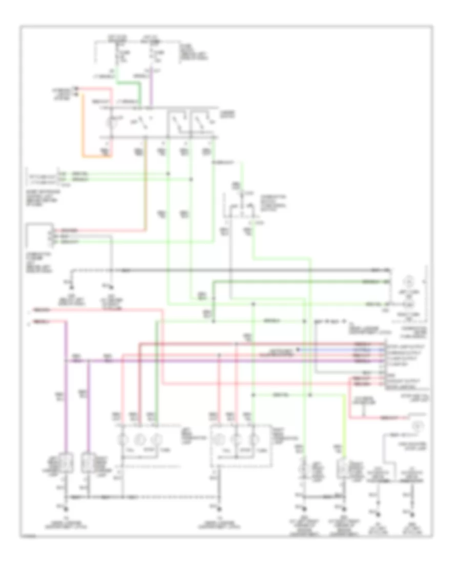
Exterior Lamps Wiring Diagram (1 of 2) for Nissan Maxima GLE 2003
List of elements for Exterior Lamps Wiring Diagram (1 of 2) for Nissan Maxima GLE 2003:
- (in relay box 1)
- 11k
- 1st
- 2nd
- Auto
- Auto light sensor (on top left side of dash)
- B106 (at right "c" pillar)
- B127 (at right "b" pillar)
- Combination switch (lighting switch)
- E11 (at left rear of engine compartment)
- E151
- E22 (at left front corner of engine compartment)
- E53 (at right front corner of engine compartment)
- E83
- Fuse & fusible link box (at left side of engine compartment)
- Fuse 10a
- Fuse 15a
- Fuse block (behind left side of dash)
- Ground
- High mounted stop light
- Hot at all times
- Joint connector 13
- Joint connector 7 (in fuse & fusible link box)
- Left front side marker lamp
- Left headlamp (parking lamp)
- Left license lamp
- M143
- M145
- M17
- M83
- Off
- Output
- Power
- Red
- Right front side marker lamp
- Right headlamp (parking lamp)
- Right license lamp
- Sensor ground
- Sensor power
- Sensor signal
- Smart entrance control unit (behind center of dash)
- Stoplight switch (on brake pedal bracket)
- Tail lamp out 1
- Tail lamp out 2
- Tail lamp sw 1
- Tail lamp sw2
- Taillamp relay (in relay box 1)
- W/ rear air spoiler
Exterior Lamps Wiring Diagram (2 of 2) for Nissan Maxima GLE 2003
List of elements for Exterior Lamps Wiring Diagram (2 of 2) for Nissan Maxima GLE 2003:
- 7k m17
- B59 (at left "b" pillar)
- B7 (at left "b" pillar)
- Combination flasher unit (behind left side of dash)
- Combination meter (turn signal)
- Combination switch (turn signal switch)
- E22 (at left front corner of engine compartment)
- E53 (at right front corner of engine compartment)
- Fuse 10a
- Fuse 15a
- Fuse block (behind left side of dash)
- Gnd
- H/mount output
- Hazard switch
- High mounted stop lamp
- Hot at all times
- Hot in on or start
- Illum
- Instrument cluster system
- Interior lights system
- Left front turn signal lamp
- Left rear combination lamp
- Left rear side marker lamp
- Left turn ind
- Lt flash out
- M144
- M151
- M25 (below left side of dash)
- M32
- M87 (at center of right ``a" pillar)
- Off
- Right front turn signal lamp
- Right rear combination lamp
- Right rear side marker lamp
- Right turn ind
- Rt flash out
- Smart entrance control unit (behind center of dash)
- Stop
- Stop and tail lamp unit
- Stop lamp output
- Stop lamp sw
- T/lamp output
- T/lamp sw
- T6 (near luggage compartment latch)
- T8 (near luggage compartment latch)
- Tail
- Turn
- W/ automatic drive positioner
- W/o automatic drive positioner
- W/o rear air spoiler
- Warning output
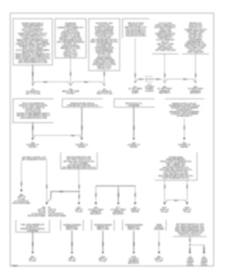
GROUND DISTRIBUTION
Ground Distribution Wiring Diagram for Nissan Maxima GLE 2003
List of elements for Ground Distribution Wiring Diagram for Nissan Maxima GLE 2003:
- A/c auto amp, front wiper motor, blower motor relay, front side marker lamp, combination switch, vehicle security horn relay-2, clutch interlock switch, left front turn signal lamp, left headlamp, left front fog lamp
- Abs actuator & electric unit, abs/tcs control unit, cooling fan relay-2, cooling fan relay-3, cooling fan motor-1, cooling fan motor-2
- Air bag diagnosis sensor unit sheild wire
- B106 (right "c" pillar)
- B12 (left "c" pillar)
- B127 (right "b" pillar)
- B128 (right "b" pillar)
- B13 (left "c" pillar)
- B44 (left "c" pillar)
- B59 (left "b" pillar) (w/ automatic drive positioner)
- B60 (left "b" pillar) (w/ automatic drive positioner)
- B62 (right "c" pillar)
- B7 (left "b" pillar) (w/o automatic drive positioner)
- Brake fluid level switch, hood switch, washer level switch, right front side marker lamp, daytime light control unit, door mirror defogger relay, combination switch, right front fog lamp, right front turn signal lamp, right headlamp
- Data link connector, electric throttle control actuator & throttle control motor, nvis (nats) immu, heated oxygen sensor 2 (bank 2), heated oxygen sensor 2 (bank 1), knock sensor shield wire
- E11 (at left rear of eng compt)
- E111 (at right front corner of eng compt)
- E149 (at front corner of eng compt)
- E22 (at left front corner of eng compt)
- E47 (front of engine)
- E48 (at right front corner of eng compt)
- E53 (at right front corner of eng compt)
- Engine control module, park/neutral position switch
- Engine control module, transmission control module, camshaft position sensor (phase) (bank 2), crankshaft position sensor, camshaft position sensor (phase) (bank 1)
- F39 (on front of engine)
- F40 (on front of engine)
- F41 (on front of engine)
- F42 (on front of engine)
- Fan control amp, fan switch, combination meter, in-vehicle sensor, mode door motor, air mix door motor, a/c control unit, a/c auto amp, left heated seat switch, right heated seat switch, intake sensor, glove box lamp, intake door motor, sunload sensor, smart entrance control unit, a/c auto amp, ambient sensor, right front power window switch, right door mirror actuator, display & navi control unit
- Fuel level sensor unit & fuel pump, engine control module, condenser
- High mounted stop lamp, left front door switch, left seat belt buckle switch, cd auto changer, left seatback heater, left rear power window switch
- Ignition coils 1-6, condenser
- J/c 7 (in fuse & fusible link box)
- Left rear combination lamp, left rear side marker lamp, right rear combination lamp, right rear side marker lamp, trunk room lamp switch, stop & taillamp unit
- Left seat control unit, left power seat switch
- M25 (below left side of dash)
- M87 (at center of right "a" pillar)
- M9 (at center of left "a" pillar)
- Power window relay, door mirror remote control switch, data link connector, tcs on/off switch, memory seat cancel switch, heated steering switch, combination switch, rear window defogger switch, a/t device, left vanity mirror, homelink universal transceiver, sunroof motor, spot lamp, right vanity mirror, auto anti-dazzling inside mirror, memory seat switch, trunk and fuel lid opener switch, front door key cylinder switch, front power window main switch, left door mirror actuator, right door mirror actuator
- Rear window defogger
- T6 (near luggae compt latch)
- T8 (near luggae compt latch)
- Telephone, fuse block, combination flasher unit, illumination control switch, combination meter, cigarette lighter, ashtray illumination, power socker, glove box lamp smart entrance control unit, air bag diagnosis sensor unit, clock, shift lock control unit, display & navi control unit
- Woofer (bose), bose speaker amp, trunk lid key cylinder switch, right license lamp, left license lamp, right front door switch, right seat belt buckle switch, high mounted stop lamp, right seatback heater, right rear power window switch, right power seat switch
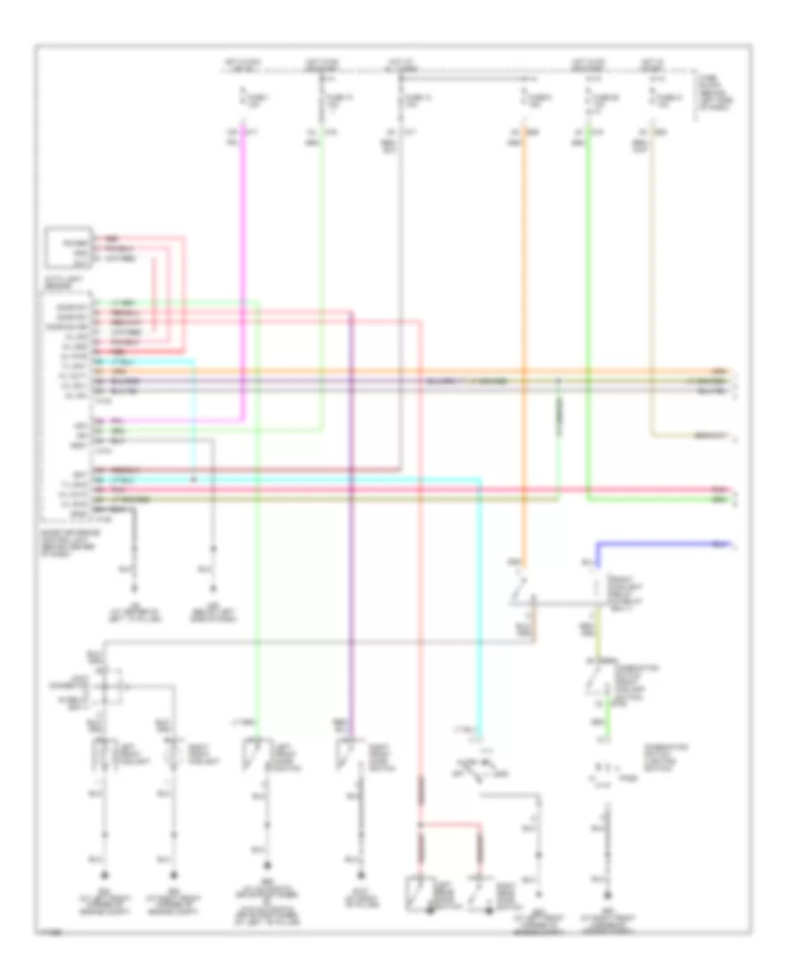
HEADLIGHTS
Headlights Wiring Diagram, with DRL (1 of 2) for Nissan Maxima GLE 2003
List of elements for Headlights Wiring Diagram, with DRL (1 of 2) for Nissan Maxima GLE 2003:
- (behind left side of dash)
- 12k
- 12l
- 1st
- 2nd
- A/l gnd
- A/l pwr
- A/l sig
- A/l sw
- Acc
- Auto
- Auto light sensor
- B127 (at right ``b" pillar)
- B59 (w/ automatic drive positioner) b7 (w/o automatic drive positioner) (at left ``b" pillar)
- Bat
- Combination switch (front foglamp switch)
- Combination switch (lighting switch)
- Door sw
- Door sw rr
- E152
- E22 (at left front corner of engine compt)
- E53 (at right front corner of engine compt)
- E83
- E89
- Front foglight relay (in relay box 1)
- Fuse 1 10a
- Fuse 10 10a
- Fuse 13 10a
- Fuse 21 10a
- Fuse 28 10a
- Fuse 6 15a
- Fuse block
- Gnd
- Gnd1
- Gnd2
- H/l out1
- H/l out2
- H/l sw1
- H/l sw2
- Hot at all times
- Hot in acc or on
- Hot in on or start
- Hot in start
- Ign
- Joint connector (in relay box 1)
- Left front door switch
- Left front foglight
- Left rear door switch
- M143
- M144
- M145
- M17
- M19
- M25 (below left side of dash)
- M9 (at center of left ``a" pillar)
- Off
- Out
- Pass
- Pnk
- Power
- Red
- Right front door switch
- Right front foglight
- Right rear door switch
- Smart entrance control unit (behind center of dash)
- T/l sw1
- T/l sw2
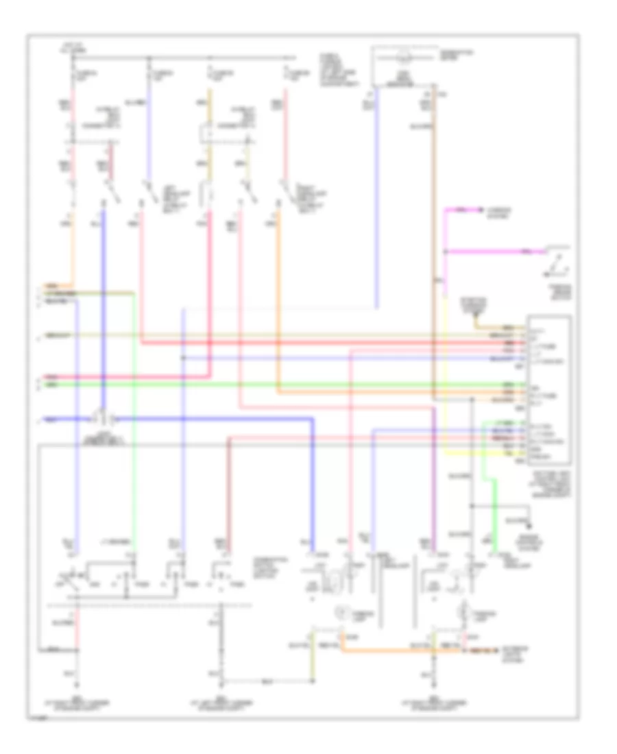
Headlights Wiring Diagram, with DRL (2 of 2) for Nissan Maxima GLE 2003
List of elements for Headlights Wiring Diagram, with DRL (2 of 2) for Nissan Maxima GLE 2003:
- (in relay box) joint connector 14
- 1st
- 2nd
- Alt-1
- Auto
- Combination meter
- Combination switch (lighting switch)
- Daytime light control unit (at right front corner of engine compt)
- E161
- E162
- E165
- E166
- E22 (at left front corner of engine compt)
- E53 (at right front corner of engine compt)
- E56
- E57
- E59
- Engine controls system
- Exterior lights system
- Fuse & fusible link box (at left side of engine compartment)
- Fuse 54 20a
- Fuse 55 20a
- Fuse 68 15a
- Fuse 69 15a
- Gnd
- Hid cont
- High
- High beam
- Hot at all times
- Ign
- Indicator
- Joint connector 11 (in relay box 1)
- L lt
- L lt fuse
- L lt main
- L lt main sw
- Left headlamp
- Left headlamp relay (in relay box 1)
- Low
- M32
- Off
- Parking brake switch
- Parking lamp
- Pass
- Pkb sw
- Pnk
- R lt
- R lt dim
- R lt fuse
- R lt main sw
- Red
- Right headlamp
- Right headlamp relay (in relay box 1)
- Starting/ charging system
- Warning system
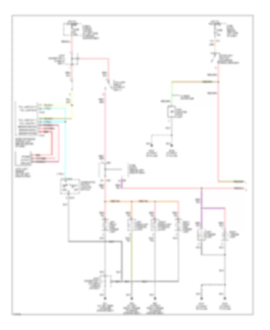
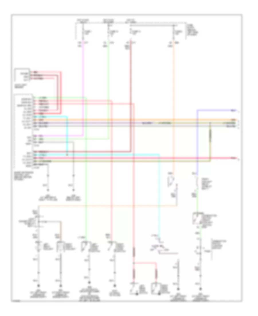
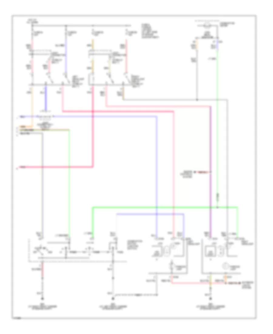
Headlights Wiring Diagram, without DRL (1 of 2) for Nissan Maxima GLE 2003
List of elements for Headlights Wiring Diagram, without DRL (1 of 2) for Nissan Maxima GLE 2003:
- (behind left side of dash)
- 12k
- 12l
- 1st
- 2nd
- A/l gnd
- A/l pwr
- A/l sig
- A/l sw
- Acc
- Auto
- Auto light sensor
- B127 (at right ``b" pillar)
- B59 (w/ automatic drive positioner) b7 (w/o automatic drive positioner) (at left ``b" pillar)
- Bat
- Combination switch (front foglight switch) e152
- Combination switch (lighting switch)
- Door sw
- Door sw (rr)
- E152
- E22 (at left front corner of engine compt)
- E53 (at right front corner of engine compt)
- E89
- Front foglight relay (in relay box 1)
- Fuse 1 10a
- Fuse 10 10a
- Fuse 13 10a
- Fuse 6 15a
- Fuse block
- Gnd
- Gnd1
- Gnd2
- H/l out1
- H/l out2
- H/l sw1
- H/l sw2
- Hot at all times
- Hot in acc or on
- Hot in on or start
- Ign
- Joint connector 13 (in relay box 1)
- Left front door switch
- Left front foglight
- Left rear door switch
- M143
- M144
- M145
- M17
- M19
- M25 (below left side of dash)
- M87 (at center of right ``a" pillar)
- Off
- Out
- Pass
- Pnk
- Power
- Red
- Right front door switch
- Right front foglight
- Right rear door switch
- Smart entrance control unit (behind center of dash)
- T/l sw1
- T/l sw2
Headlights Wiring Diagram, without DRL (2 of 2) for Nissan Maxima GLE 2003
List of elements for Headlights Wiring Diagram, without DRL (2 of 2) for Nissan Maxima GLE 2003:
- 1st
- 2nd
- Auto
- Combination meter
- Combination switch (lighting switch)
- E161
- E162
- E165
- E166
- E22 (at left front corner of engine compt)
- E53 (at right front corner of engine compt)
- Engine controls system
- Exterior lights system
- Fuse & fusible link box (at left side of engine compartment)
- Fuse 54 20a
- Fuse 55 20a
- Fuse 68 15a
- Fuse 69 15a
- Hid cont
- High
- High beam indicator
- Hot at all times
- Joint connector (in relay box 1)
- Joint connector 11 (in relay box 1)
- Left headlamp
- Left headlamp relay (in relay box 1)
- Low
- M32
- Off
- Parking lamp
- Pass
- Pnk
- Right headlamp
- Right headlamp relay (in relay box 1)
HORN
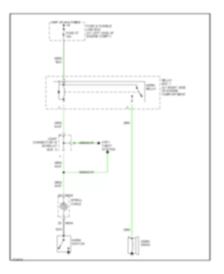
Horn Wiring Diagram for Nissan Maxima GLE 2003
List of elements for Horn Wiring Diagram for Nissan Maxima GLE 2003:
- Anti- theft system
- Fuse & fusible link box (at left side of engine compt)
- Fuse 57 10a
- Horn (high)
- Horn relay
- Horn switch
- Hot at all times
- Joint connector 12 (in relay box 1)
- M154
- M644
- Nca
- Relay box 1 (at right side of engine compartment
- Spiral cable
INSTRUMENT CLUSTER
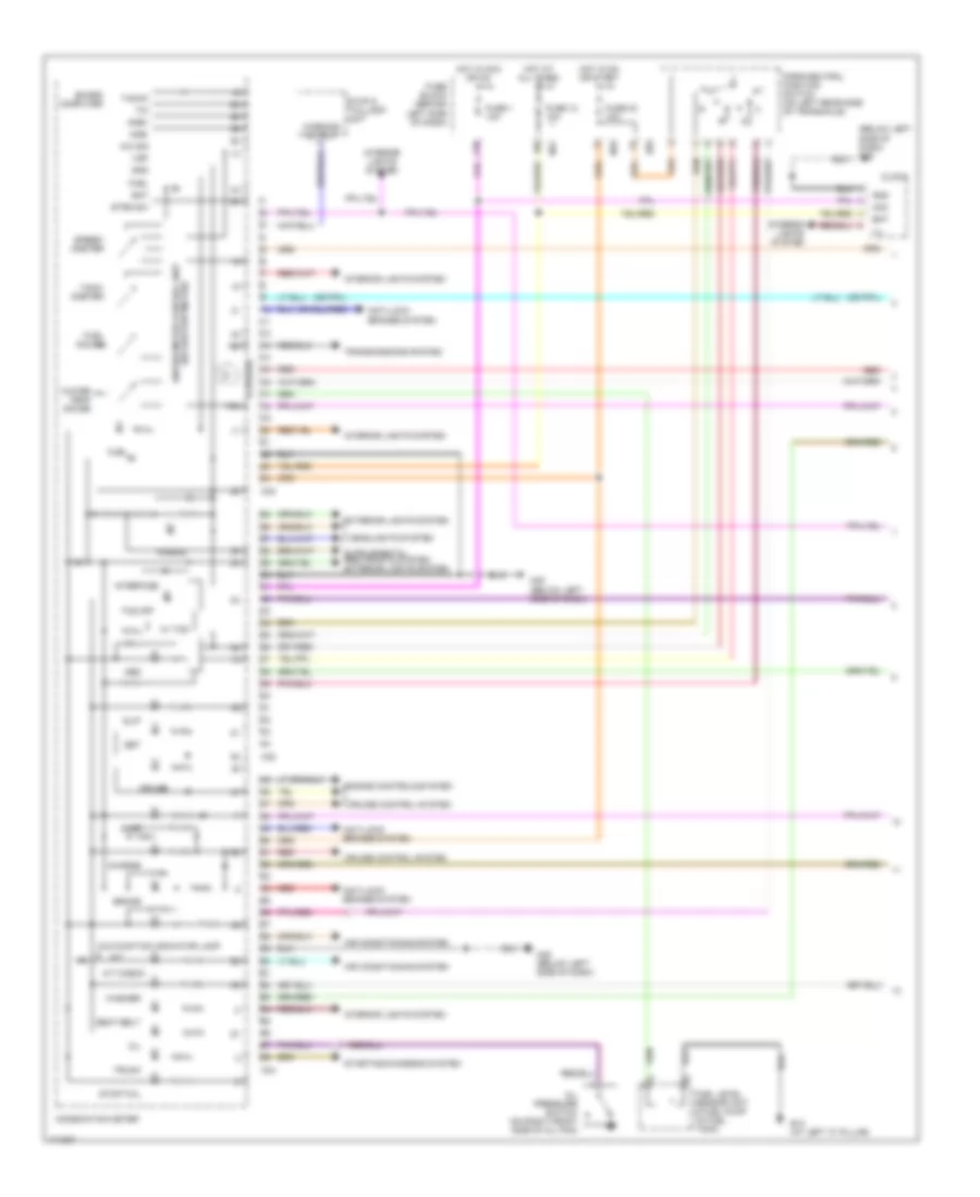
Instrument Cluster Wiring Diagram (1 of 2) for Nissan Maxima GLE 2003
List of elements for Instrument Cluster Wiring Diagram (1 of 2) for Nissan Maxima GLE 2003:
- (4 bulbs)
- (below left side of dash) m25
- (w/ odo/trip meter) unified meter control unit
- 10k
- 12k
- A/c sig
- A/t
- A/t check
- Abs
- Acc
- Air conditioning system
- Airbag
- Amb+
- Amb-
- Anti-lock brakes system
- B13 (at left "c" pillar)
- Bat
- Board computer
- Brake
- Charge
- Clock
- Combination meter
- Cruise
- Cruise control system
- D00r
- E83
- Engine controls system
- Exterior lights system
- Fuel
- Fuel gauge
- Fuel level sensor unit & fuel pump (in fuel tank)
- Fuse 1 10a
- Fuse 12 10a
- Fuse 30 10a
- Fuse block (behind left side of dash)
- Gnd
- Headlights system
- Hot at all times
- Hot in acc or on
- Hot in on or start
- Ill
- Interface
- Interior lights system
- M17
- M19
- M25 (below left side of dash)
- M32
- M33
- M34
- Malfunction indicator lamp
- Oil
- Oil pressure switch (on right front side of oil pan)
- Park/neutral position switch (on left rear side of transaxle)
- Red
- Seat belt
- Set
- Slip
- Speed- ometer
- Starting/charging system
- Stop & taillamp unit
- Stop/tail
- Strg sw
- Tach- ometer
- Tacho
- Tcs off
- Tim
- Transmissions system
- Trunk
- Vsp
- W/ tcs
- Warning output
- Washer
- Water temp gauge
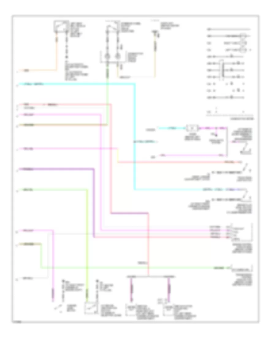
Instrument Cluster Wiring Diagram (2 of 2) for Nissan Maxima GLE 2003
List of elements for Instrument Cluster Wiring Diagram (2 of 2) for Nissan Maxima GLE 2003:
- (a/t)
- (at base of parking brake lever assembly) parking brake switch
- (m/t)
- (w/o automatic driver positioner) b59 (w/ automatic driver positioner) (at left "b" pillar)
- A/t check ind
- A/t device (3rd position switch) (at base of selector lever)
- Abs actuator & electric unit (at left rear corner of engine compartment)
- Abs/tcs control & electric unit (at left rear corner of engine compartment)
- Audio unit (behind center of dash)
- Brake fluid level switch (on master cylinder reservoir)
- Canada
- Combination meter
- Combination switch (spiral cable)
- Diode (behind left side of dash)
- E53 (at right front corner of engine compartment)
- E53 (at right front corner of engine compt)
- Engine control module (ecm) (behind lower center of dash)
- Gnd
- Headlights system
- High beam
- Interface
- Left seat belt buckle switch (in left seat belt buckle)
- Left turn
- M158
- M644
- M68
- M9 (at center of left "a" pillar)
- Meter out
- Nca
- Red
- Right turn
- Steering wheel switch (drive computer)
- T6 (near luggage compartment latch)
- Tach out
- Tim
- Transmission control module (tcm) (behind lower center of dash)
- Trunk room lamp switch
- Two
- Usa
- Vsp-8
- W/ tcs
- W/o tcs
- Washer level switch
INTERIOR LIGHTS
Courtesy Lamps Wiring Diagram for Nissan Maxima GLE 2003
List of elements for Courtesy Lamps Wiring Diagram for Nissan Maxima GLE 2003:
- (a/t) (m/t)
- (m/t) (a/t)
- 12l
- B127 (at right "b" pillar)
- B7 (w/o automatic drive positioner) b59 (w/ automatic drive positioner) (at left "b" pillar)
- Bat (fuse)
- Bat saver out
- Between full stroke and n
- Com
- Communication if
- Cpu
- D10
- D13
- Door
- Door lock & unlock sw
- Door sw (as)
- Door sw (dr)
- Door sw (rr)
- Front power window main switch
- Full stroke lock sw
- Full stroke unlock sw
- Fuse 10a
- Fuse block (behind left side of dash)
- Ground 1
- Ground 2
- Hot at all times
- Hot in on or start
- Ign
- Ignition keyhole illumination
- Interior lamp
- Key light out
- Key switch
- Left front door key cylinder switch
- Left front door switch
- Left front step lamp
- Left rear door switch
- Left vanity mirror (illum)
- Lock
- M143
- M144
- M145
- M17
- M19
- M25 (beelow left side of dash)
- M87 (at center of right "a" pillar)
- M9 (at center of left "a" pillar)
- Off
- Red
- Right front door switch
- Right front power window switch
- Right front step lamp
- Right rear door switch
- Right vanity mirror (illum)
- Room lamp out
- Smart entrance control unit (behind center of dash)
- Spot lamp
- Step lamp out
- T6 (near luggage compartment latch)
- T8 (near luggage compartment latch)
- Trunk room lamp
- Trunk room lamp switch
- Unlock
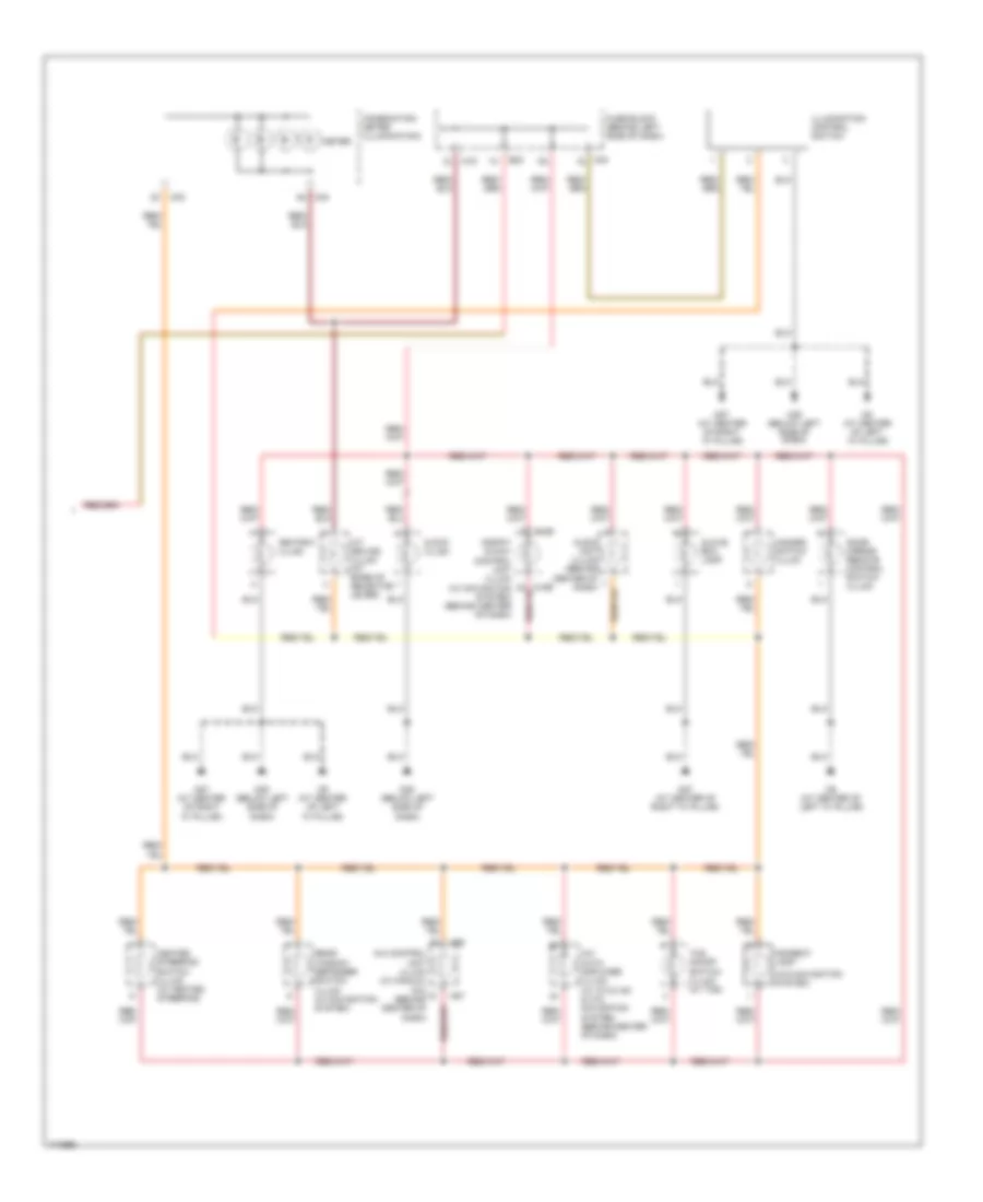
Instrument Illumination Wiring Diagram (1 of 2) for Nissan Maxima GLE 2003
List of elements for Instrument Illumination Wiring Diagram (1 of 2) for Nissan Maxima GLE 2003:
- (at left "b" pillar)
- 12k
- 12l
- 1st
- 2nd
- A/l sensor gnd
- A/l sensor pwr
- A/l sensor sig
- A/l sw
- Accessory
- Auto
- Auto light sensor (on top left side of dash)
- B106 (at right "c" pillar)
- B127 (at right "b" pillar)
- B7 (w/o auomatic drive positioner) b59 (w/ automatic drive positioner)
- Bat (fuse)
- Combination switch (lighting switch)
- Door sw (as)
- Door sw (dr)
- Door sw (rr)
- E22 (at left front corner of engine compartment)
- E53 (at right front corner of engine compartment)
- Fuse 10a
- Fuse & fusible link box (at left side of engine compartment)
- Fuse block (behind left side of dash)
- Gnd 1
- Gnd 2
- Ground
- Hot at all times
- Hot in acc or on
- Hot in on or start
- Ignition
- Joint connector 13 (in relay box 1)
- Left front door switch
- Left rear door switch
- M143
- M144
- M145
- M17
- M19
- M25 (below left side of dash)
- M87 (at center of right "a" pillar)
- Off
- Output
- Power
- Red
- Right front door switch
- Right rear door switch
- Smart entrance control unit (behind center of dash)
- T/l out 1
- T/l out 2
- T/l sw 1
- T/l sw 2
- Taillamp relay (in relay box 1)
Instrument Illumination Wiring Diagram (2 of 2) for Nissan Maxima GLE 2003
List of elements for Instrument Illumination Wiring Diagram (2 of 2) for Nissan Maxima GLE 2003:
- (w/o navigation system)
- 16l
- A/c auto amplifier (illum) (w/ atuo a/c & w/o navigation system) (behind center of dash)
- A/c control unit (illum) (w/ manual a/c) (behind center of dash)
- A/t device (illum) (at base of selector lever)
- Ashtray (illum)
- Audio unit (illum) (behind center of dash)
- Clock (illum)
- Combination meter (illumination)
- Dispay & navi control unit (illum) (w/ navigation system) (behind center of dash)
- Door mirror remote control switch (illum)
- E83
- Fuse block (behind left side of dash)
- Glove box lamp
- Hazard switch (illum)
- Heated steering switch (illum) (w/ heated steering)
- Illumination control switch
- Indirect lamp
- M168
- M169
- M19 2l
- M19 5l
- M25 (below left side of dash)
- M33
- M34
- M56
- M57
- M87 (at center of right "a" pillar)
- M87 (at center of right "a" pillar)
- M9 (at center of left "a" pillar)
- Meter
- Rear window defogger switch (illum) (w/ navigation system)
- Tcs on/off switch (illum) (w/ tcs)
MEMORY SYSTEMS
Memory Seat Wiring Diagram (1 of 2) for Nissan Maxima GLE 2003
List of elements for Memory Seat Wiring Diagram (1 of 2) for Nissan Maxima GLE 2003:
- (at center of left "a" pillar) m9
- (at left "b" pillar) b59
- (at left "b" pillar) b60
- 10k m17
- 12l m19
- 3k m17
- 5j b5
- A/t device (park position switch) (w/ a/t) (at base of selector lever)
- B512
- B513
- Batt
- Cancel sw
- Circuit breaker (behind left side of dash)
- Combination meter
- Front dn mtr
- Front dn sw
- Front up mtr
- Front up sw
- Fuse & fusible link box (at left side of engine compt)
- Fuse 10a
- Fuse block (behind left side of dash)
- Fuse i 40a
- Fwd rec mtr
- Fwd rec sw
- Fwd slide mtr
- Fwd sliding sw
- Gnd
- Gnd (sig)
- Hot at all times
- Hot in on or start
- Hot in start
- Ign
- Indicator
- Instrument cluster system
- Key sw
- Key switch (w/ a/t)
- Left front door switch
- Left ft dr sw
- Left seat control unit
- M33
- Mem ind-1
- Mem ind-2
- Mem set-1
- Mem set-2
- Memory seat cancel switch
- P range sw
- Parking brake switch (w/ m/t) (at base of parking brake lever assembly)
- Pnk
- Power out
- Pulse f lift sw
- Pulse r lift sw
- Pulse rec sw
- Pulse slide sw
- Pulse sw gnd
- Rear dn mtr
- Rear dn sw
- Rear up mtr
- Rear up sw
- Red
- Rwd rec mtr
- Rwd rec sw
- Rwd slide mtr
- Rwd sliding sw
- Seat memory switch
- Set sw
- Set switch
- Speed sensor
- Start
- Switch
- W/ a/t
Memory Seat Wiring Diagram (2 of 2) for Nissan Maxima GLE 2003
List of elements for Memory Seat Wiring Diagram (2 of 2) for Nissan Maxima GLE 2003:
- B59 (at left "b" pillar)
- Encoder
- Fwd
- Left front lifting device
- Left power seat switch
- Left rear lifting device
- Left reclining device
- Left sliding device
- Lifting switch (front)
- Lifting switch (rear)
- Pnk
- Reclining switch
- Rwd
- Sliding switch
POWER DISTRIBUTION
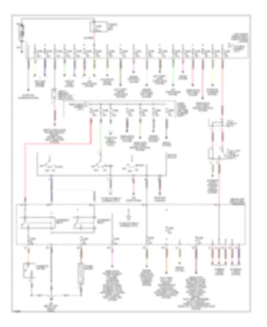
Power Distribution Wiring Diagram (1 of 2) for Nissan Maxima GLE 2003
List of elements for Power Distribution Wiring Diagram (1 of 2) for Nissan Maxima GLE 2003:
- (behind left side of dash) fuse block
- (left side of engine compt) fuse & fusible link box
- Acc
- Accessory relay
- Air conditioning
- Air conditioning system
- Anti-lock brakes system
- Anti-theft, data link, memory, transmissions, telephone, air conditioning, instrument cluster, engine controls system
- Anti-theft, horn, door locks system
- Anti-theft, horns, door locks system
- Battery
- Cigarette lighter
- Circuit breaker (behind left side of dash)
- Cooling fans system
- Engine controls system
- Engine controls, anti-theft system
- Engine controls, headlights, starting/ charging, memory, system
- Exterior lights system
- Exterior lights, interior lights, warning system
- From fuse 60 a (diagram 1 of 1)
- Fuse & fusible link box (left side of engine compt)
- Fuse 10a
- Fuse 15a
- Fuse 20a
- Fuse a 120a
- Fuse b 80a
- Fuse c 40a
- Fuse d 40a
- Fuse e 40a
- Fuse g 40a
- Fuse h 40a
- Fuse i 40a
- Fuse j 80a
- Fusible link box
- Headlamps, anti-theft, engine controls, system
- Headlights, anti-theft system
- Headlights, anti-theft, engine controls system
- Headlights, exterior lights, body cpmputer, interior lights, warning systems, power tops, power windows, door locks, memory, anti-theft, defogger, shift intrlock, homelink transceiver trunk lid, tailgate & fuel door system
- Headlights, power antenna, anti-theft, mirrors, telephone, navigation, sound systems, interior lights, exterior lights instrument cluster, door locks, body computer system
- Ignition switch
- Interior lights system
- J/c 13 (in relay box 1)
- M25 (below left side of dash)
- Memory system
- Navigation, sound system
- Nca
- Off
- Power socket
- Red
- Seats system
- Seats, door locks, power windows, memory, power tops, body computer system
- Sound system
- Start
- Starting/ charging
- Starting/ charging system
- Tail lamp relay (in relay box 1)
- To fuse b (diagram 1 of 1)
- To ignition relay (diagram 2 of 2)
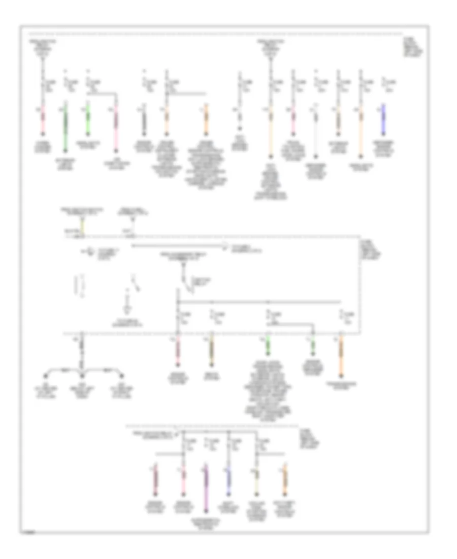
Power Distribution Wiring Diagram (2 of 2) for Nissan Maxima GLE 2003
List of elements for Power Distribution Wiring Diagram (2 of 2) for Nissan Maxima GLE 2003:
- 11k
- 15l
- 7l red
- Air conditioning system
- Anti- lock brakes system
- Anti- lock brakes, cruise control, exterior lights, transmissions, shift interlock
- Anti-theft, engine controls system
- Cooling fans, starting/ charging system
- Cruise control, instrument cluster, exterior lights, transmissions, navigation system
- Defogger, engine controls system
- Door locks, transmissions, headlights exterior lights, interior lights, warning systems, defogger, power tops, telephone, power windows, memory seats, anti-theft, navigation, computer data lines, homelink transceiver, body computer system
- Engine controls system
- Engine controls, defogger system
- Exterior lights system
- From accessory relay (diagram 1 of 2)
- From fuse j (diagram 1 of 2)
- From ignition relay (diagram 2 of 2)
- From ignition relay e (diagram 2 of 2)
- From ignition switch (diagram 1 of 2)
- Fuse 10a
- Fuse 15a
- Fuse 20a
- Fuse block (behind left side of dash)
- Headlights system
- Ignition relay
- M25 (below left side of dash)
- M87 (at center of right "a" pillar)
- M9 (at center of left "a" pillar)
- Pnk
- Red
- Seats system
- Shift interlock system
- To fuse 17 (diagram 2 of 2)
- To fuse 2 (diagram 2 of 2)
- To fuse 25 (diagram 2 of 2)
- Transmissions system
- Trunk, tailgate & fuel doors, door locks system
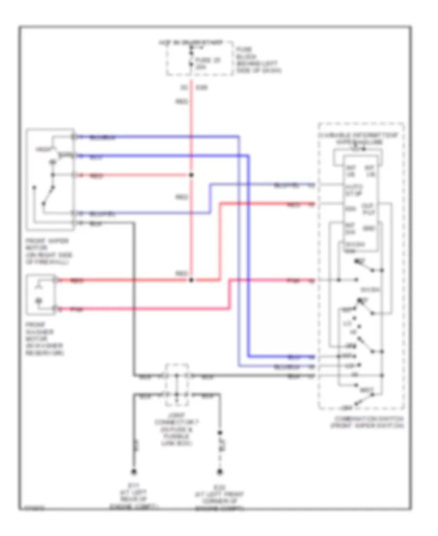
- Wiper/ washer system
POWER DOOR LOCKS
Power Door Locks Wiring Diagram for Nissan Maxima GLE 2003
List of elements for Power Door Locks Wiring Diagram for Nissan Maxima GLE 2003:
- (a/t)
- (at center of left ``a" pillar) m9
- (at center of right ``a" pillar) m87
- (at left ``b" pillar) b7 (w/o automatic drive positioner) b59 (w/ automatic drive positioner)
- (below left side of dash) m25
- (m/t)
- 12k m17
- 12l m19
- 8k m17
- Acc
- Anti-theft system
- B127 (at right ``b" pillar)
- Bat (fuse)
- Bat (ptc)
- Batt saver out
- Between lock full stroke and n
- Between unlock full stroke and n
- Circuit breaker (behind left side of dash)
- Closed
- Com
- Comm i/f
- Cpu
- D10
- Data (rx)
- Data (tx)
- Data link connector (below left side of dash)
- Door lock & unlock switch
- Door lock out (all)
- Door sw (as)
- Door sw (dr)
- Door sw (rr)
- Door unlk out (as, rr)
- Door unlk out (dr)
- Exterior lights system
- Flasher lh out
- Flasher rh out
- Fuse 10a
- Fuse block (behind left side of dash)
- Gnd1
- Gnd2
- H/l out 1
- H/l out 2
- Headlights system
- Horn out
- Hot at all times
- Hot in acc or on
- Hot in on or start
- Ign
- Interior lights system
- Key ring light out
- Key sw
- Key switch
- Left front door key cylinder switch
- Left front door lock actuator
- Left front door switch
- Left front power window switch
- Left rear door lock actuator
- Left rear door switch
- Lock
- M143
- M144
- M145
- O13
- Open
- Out
- Pnk
- Red
- Right front door lock actuator
- Right front door switch
- Right front power window switch
- Right rear door lock actuator
- Right rear door switch
- Room lamp out
- Smart entrance control unit (behind center of dash)
- Unlock
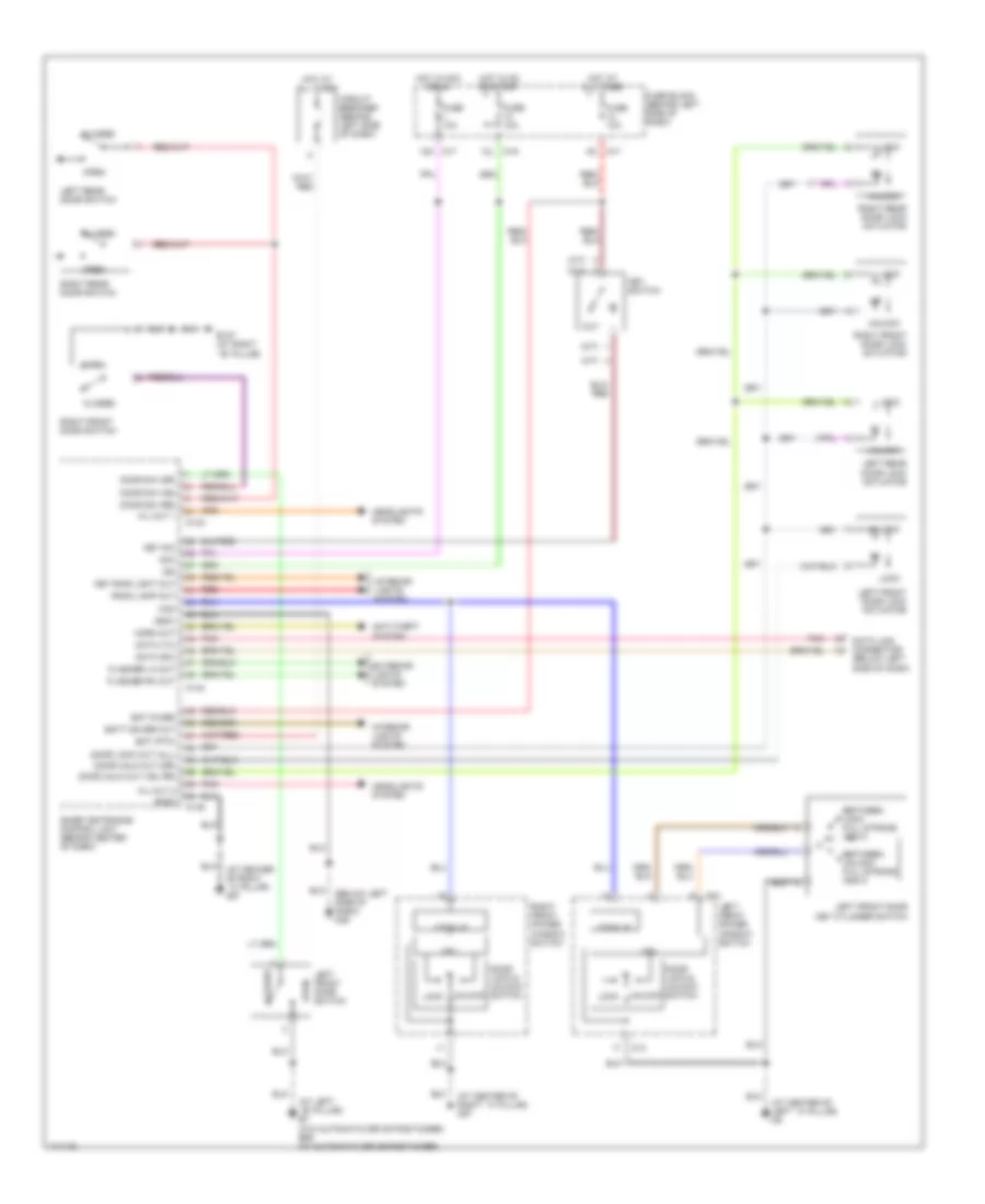
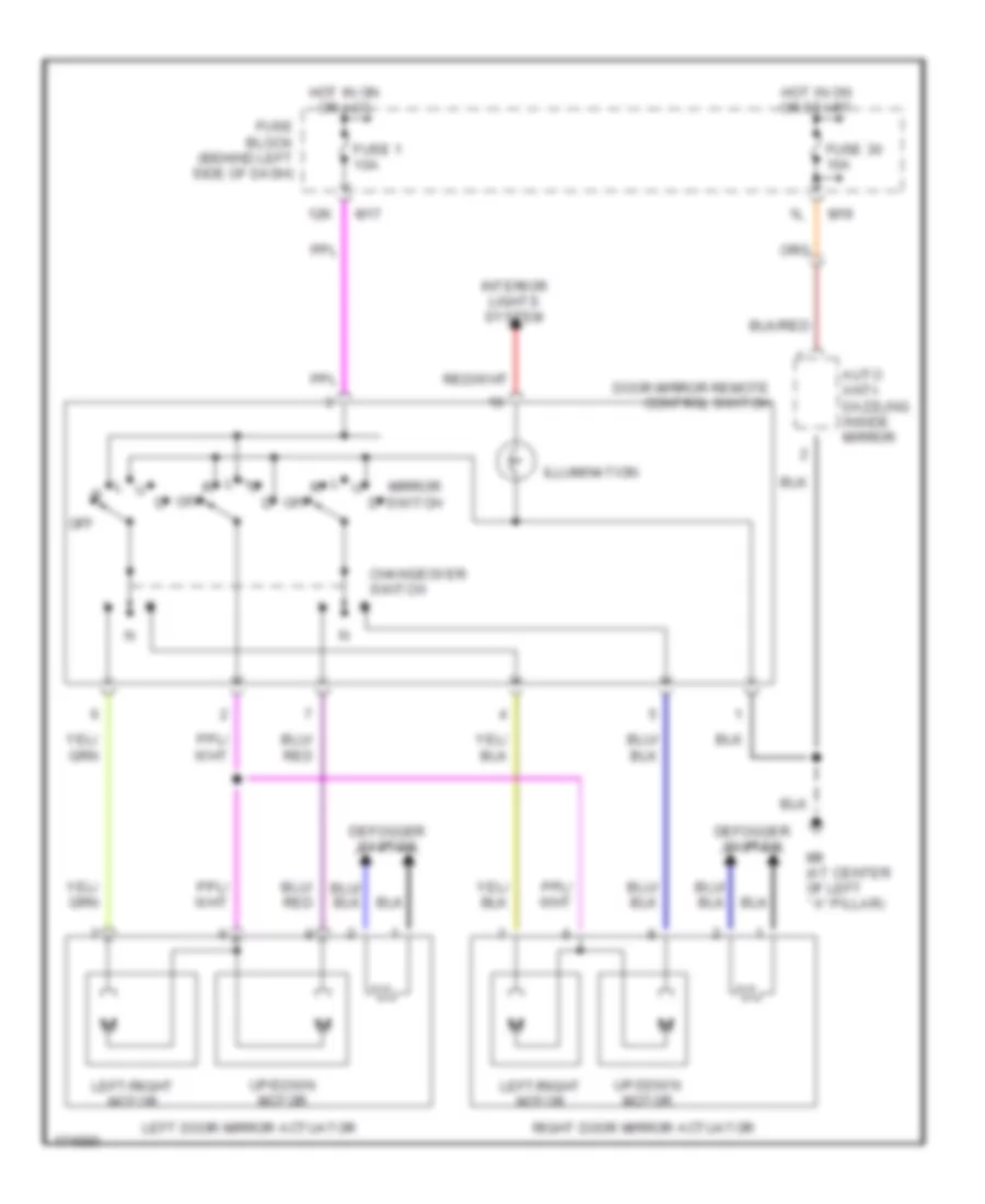
POWER MIRRORS
Power Mirrors Wiring Diagram for Nissan Maxima GLE 2003
List of elements for Power Mirrors Wiring Diagram for Nissan Maxima GLE 2003:
- 12k
- Auto anti- dazzling inside mirror
- Changeover switch
- Defogger system
- Door mirror remote control switch
- Fuse 1 10a
- Fuse 30 10a
- Fuse block (behind left side of dash)
- Hot in on or acc
- Hot in on or start
- Illumination
- Interior lights system
- Left door mirror actuator
- Left/right motor
- M17
- M19
- M9 (at center of left ``a" pillar)
- Mirror switch
- Off
- Right door mirror actuator
- Up/down motor
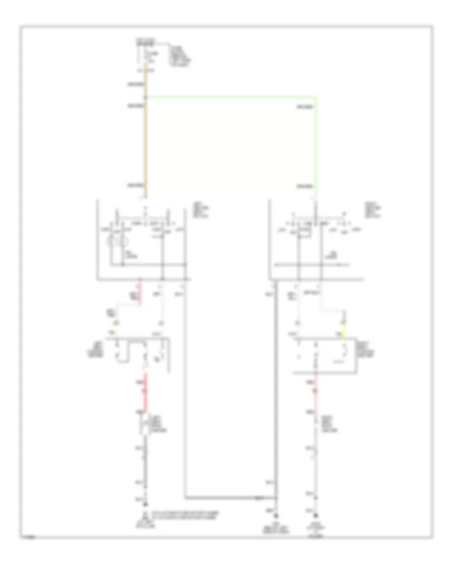
POWER SEATS
Heated Seats Wiring Diagram for Nissan Maxima GLE 2003
List of elements for Heated Seats Wiring Diagram for Nissan Maxima GLE 2003:
- "c" pillar)
- (w/ automatic drive positioner)
- (w/o automatic drive positioner)
- 10l m19
- B106 (at right
- B59 (at left "b" pillar)
- Fuse 10a
- Fuse block (behind left side of dash)
- High
- High off
- Hot in on or start
- Ind lamps
- Left heated seat switch
- Left seat back heater
- Left seat cushion heater
- Low
- M25 (below left side of dash)
- Off
- Red
- Right heated seat switch
- Right seat back heater
- Right seat cushion heater
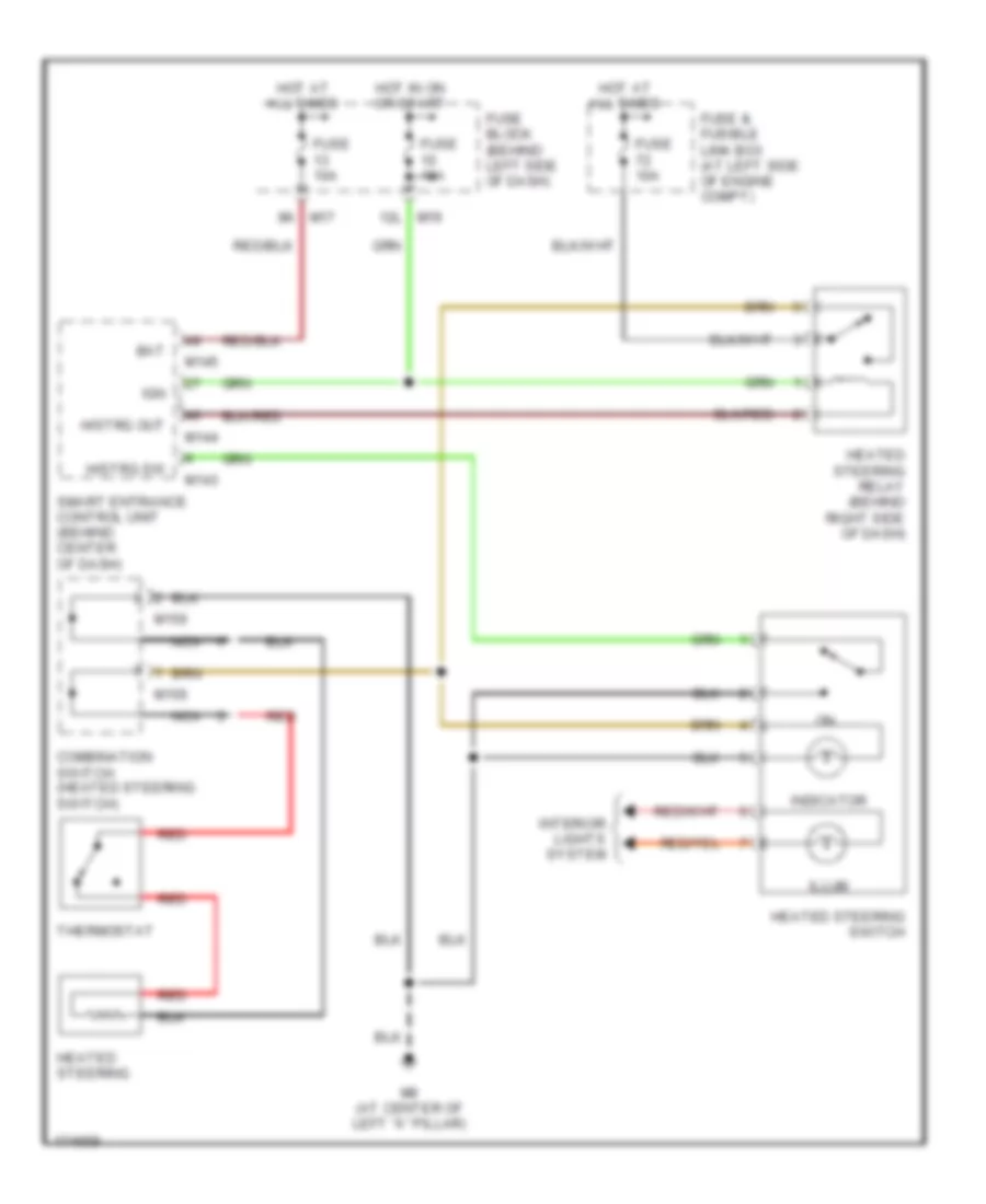
Heated Steering Wheel Wiring Diagram for Nissan Maxima GLE 2003
List of elements for Heated Steering Wheel Wiring Diagram for Nissan Maxima GLE 2003:
- 12l m19
- 8k m17
- Bat
- Combination switch (heated steering switch)
- Fuse & fusible link box (at left side of engine compt)
- Fuse 10a
- Fuse block (behind left side of dash)
- H/strg out
- H/strg sw
- Heated steering
- Heated steering relay (behind right side of dash)
- Heated steering switch
- Hot at all times
- Hot in on or start
- Ign
- Illum
- Indicator
- Interior lights system
- M143
- M144
- M145
- M156
- M9 (at center of left "a" pillar)
- Nca
- Red
- Smart entrance control unit (behind center of dash)
- Thermostat
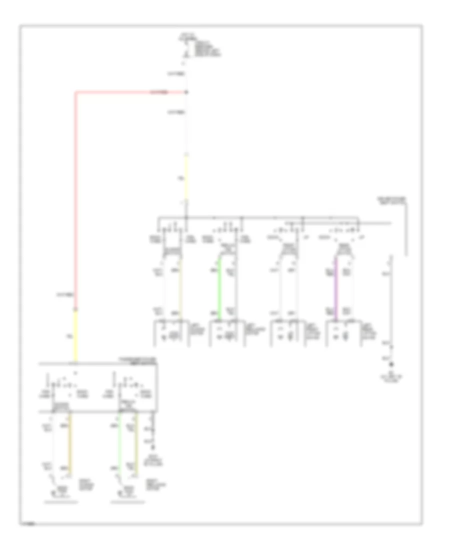
Power Seat Wiring Diagram for Nissan Maxima GLE 2003
List of elements for Power Seat Wiring Diagram for Nissan Maxima GLE 2003:
- B127 (at right "b" pillar)
- B7 (at left "b" pillar)
- Back fwd
- Back- ward
- Circuit breaker (behind left side of dash)
- Down
- Driver power seat switch
- For- ward
- Front lifting switch
- Fwd back
- Hot at all times
- Left front lifting motor
- Left rear lifting motor
- Left reclining motor
- Left sliding motor
- Passenger power seat switch
- Rear lifting switch
- Reclin- ing switch
- Right reclining motor
- Right sliding motor
- Sliding switch
- Up dn
POWER TOP/SUNROOF
Power Top/Sunroof Wiring Diagram for Nissan Maxima GLE 2003
List of elements for Power Top/Sunroof Wiring Diagram for Nissan Maxima GLE 2003:
- 12l
- B106 (at right "c" pillar)
- B7 (w/o automatic drive positioner) b59 (w/ automatic drive positioner) (at left "b" pillar)
- Bat (fuse)
- Circuit breaker (behind left side of dash)
- Cpu
- Encoder
- Fuse & fusible link box (at left side of engine compartment)
- Fuse 10 10a
- Fuse 13 10a
- Fuse block (behind left side of dash)
- Fuse i 40a
- Ground1
- Ground2
- Hot at all times
- Hot in on or start
- Ignition
- Left front door switch
- Lf door sw
- M143
- M144
- M145
- M17
- M19
- M25 (below left side of dash)
- M87 (at center of right "a" pillar)
- M9 (at center of left "a" pillar)
- Pnk
- Pre-select switch
- Rap output
- Rf door sw
- Right front door switch
- Slide limit sw
- Smart entrance control unit (behind center of dash)
- Sun roof motor
- Sun roof switch
- Tilt limit sw
- Tilt switch
POWER WINDOWS
Power Windows Wiring Diagram (1 of 2) for Nissan Maxima GLE 2003
List of elements for Power Windows Wiring Diagram (1 of 2) for Nissan Maxima GLE 2003:
- 12l
- Auto dn
- Auto up
- Battery (fuse)
- Circuit breaker (behind left side of dash)
- Com
- Cpu
- D10
- D13
- Door sw (as)
- Door sw (dr)
- Down
- Encoder
- Front power window main switch
- Fuse & fusible link box (at left side of engine compartment)
- Fuse 10a
- Fuse block (behind left side of dash)
- Fuse i 40a
- Gnd1
- Gnd2
- Hot at all times
- Hot in on or start
- Ignition
- Illuminaton
- Interior lights system
- Left front
- Left front door key cylinder switch
- Left front power window regulator
- Left rear power window regulator
- Left rear power window switch
- Left rear switch
- Limit switch
- Lock
- Locked
- M143
- M144
- M145
- M17
- M19
- M25 (below left side of dash)
- M87 (at center of
- M9 (at center of left "a" pillar)
- Power window relay (behind left side of dash)
- Rap output
- Red
- Right "a" pillar)
- Right front
- Right rear switch
- Smart entrance control unit (behind center of dash)
- Unlk
- Unlocked
- Window lock switch
Power Windows Wiring Diagram (2 of 2) for Nissan Maxima GLE 2003
List of elements for Power Windows Wiring Diagram (2 of 2) for Nissan Maxima GLE 2003:
- Auto dn
- Auto up
- B12 (at left "c" pillar)
- B127 (at right "b" pillar)
- Cpu
- Down
- Encoder
- Illumination
- Illuminaton
- Interior lights system
- Left front door switch
- Limit switch
- M87 (at center of
- Right "a" pillar)
- Right front
- Right front door switch
- Right front power window regulator
- Right front power window switch
- Right rear power window regulator
- Right rear power window switch
RADIO
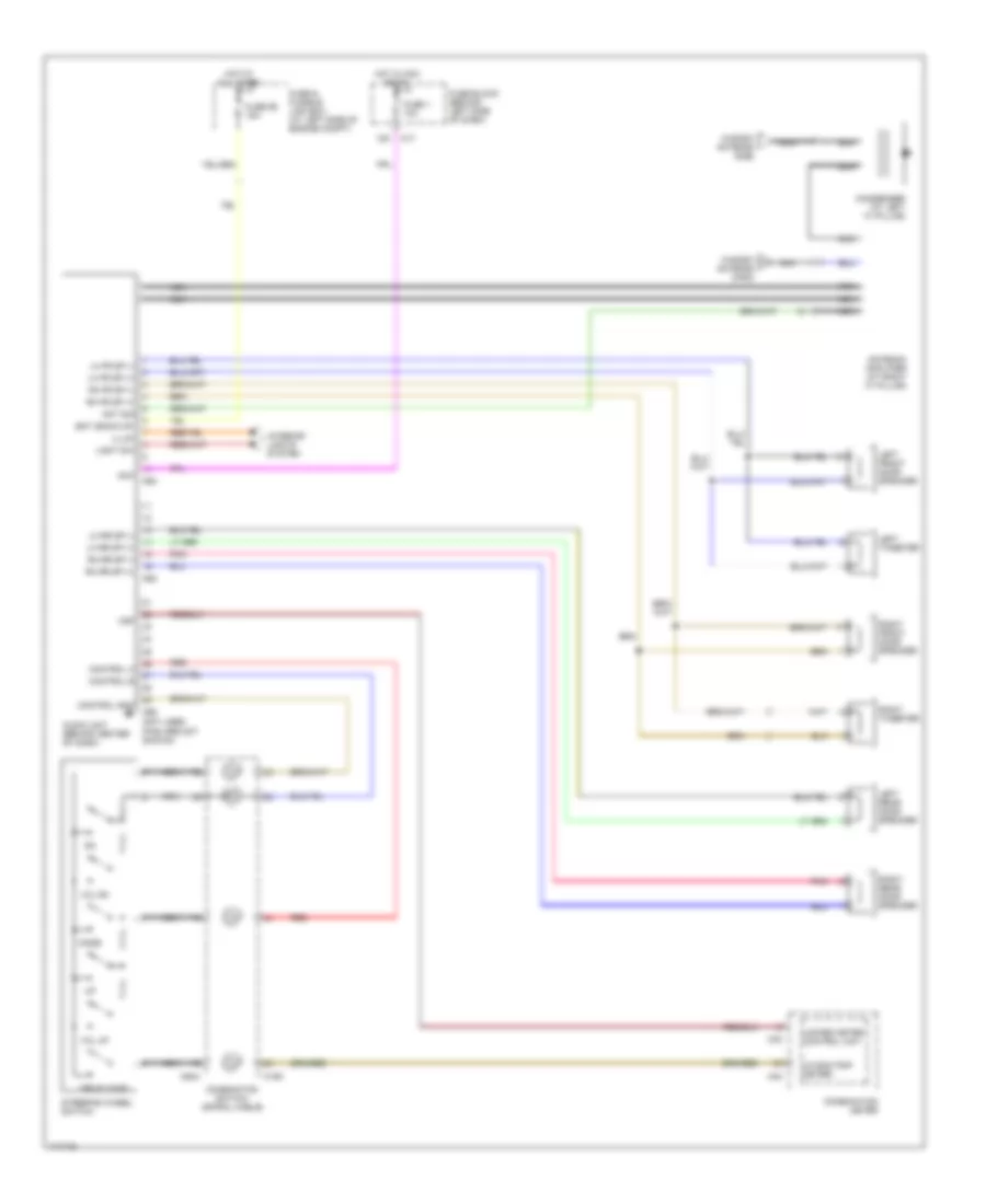
Radio Wiring Diagram, Base for Nissan Maxima GLE 2003
List of elements for Radio Wiring Diagram, Base for Nissan Maxima GLE 2003:
- acc
- control a control b
- lh fr sp (-) lh fr sp (+)
- vsp
- (not used pins are not shown)
- (w/odo/trip meter)
- 12k
- Antenna amplifier (at right ``c" pillar)
- Audio unit (behind center of dash)
- Combination meter
- Combinaton switch (spiral cable)
- Condenser (at left ``c" pillar)
- Control gnd
- Drive comp
- Fuse & fusible link box (at left side of engine compt)
- Fuse 1 10a
- Fuse 56 15a
- Fuse block (behind left side of dash)
- Hot at all times
- Hot in acc or on
- Illum light sw
- Interior lights system
- Left front door speaker
- Left rear door speaker
- Left tweeter
- Lh rr sp (+)
- Lh rr sp (-)
- M158
- M17
- M33
- M34
- M63
- M64
- M644
- M68
- Mode
- Nca
- Pnk
- Red
- Rh fr sp (+) ant sig bat (back-up)
- Rh fr sp (-)
- Rh rr sp (-) rh rr sp (+)
- Right front door speaker
- Right rear door speaker
- Right tweeter
- Steering wheel switch
- Unified meter control unit
- Vol dn
- Vol up
- Window antenna (main)
- Window antenna (sub)
Radio Wiring Diagram, Bose (1 of 2) for Nissan Maxima GLE 2003
List of elements for Radio Wiring Diagram, Bose (1 of 2) for Nissan Maxima GLE 2003:
- (at right ``c" pillar) b106
- +b (12v)
- 12k
- Acc
- Ant sig
- Antenna amplifier (at right ``c" pillar)
- Audio unit (behind center of dash)
- B106 (at right "c" pillar)
- Bat (back-up)
- Bose speaker amplifier (under rear parcel shelf)
- Cd lh in (+)
- Cd lh in (-)
- Cd rh in (+)
- Cd rh in (-)
- Condenser (at left "c" pillar)
- Control a
- Control b
- Control gnd
- Fuse & fusible link box (at left side of engine compt)
- Fuse 1 10a
- Fuse 56 15a
- Fuse 67 15a
- Fuse block (behind left side of dash)
- Gnd
- Ground
- Hot at all times
- Hot in acc or on
- Illum
- Interior lights system
- Left front door speaker
- Left rear door speaker
- Left tweeter
- Lf fr sp (-)
- Lh fr sp (+)
- Lh fr sp (-)
- Lh rr sp (+)
- Lh rr sp (-)
- Light sw
- M17
- M61
- M62
- M68
- Nca
- On/off sig
- On/off signal
- Pnk
- Red
- Req
- Rh fr sp (+)
- Rh fr sp (+)
- Rh fr sp (-)
- Rh fr sp (-)
- Rh rr sp (+)
- Rh rr sp (-)
- Rh rr sp (-)
- Right front door speaker
- Right rear door speaker
- Right tweeter
- Vsp
- W/ cd auto changer
- Window antenna (main)
- Window antenna (sub)
- Woofer
- Woofer (+)
- Woofer (-)
Radio Wiring Diagram, Bose (2 of 2) for Nissan Maxima GLE 2003
List of elements for Radio Wiring Diagram, Bose (2 of 2) for Nissan Maxima GLE 2003:
- Acc
- B12 (at left ``c" pillar)
- Back up
- Cd auto changer
- Combination meter
- Combinaton switch (spiral cable)
- Drive comp
- Gnd
- Lh (+) out
- Lh (-) out
- M158
- M33
- M34
- M644
- Mode
- Nca
- Red
- Req
- Rh (+) out
- Rh (-) out
- Rxd
- Steering wheel switch
- Strg sw
- Txd
- Unified meter control unit (w/odo/trip meter)
- Vol dn
- Vol up
SHIFT INTERLOCK
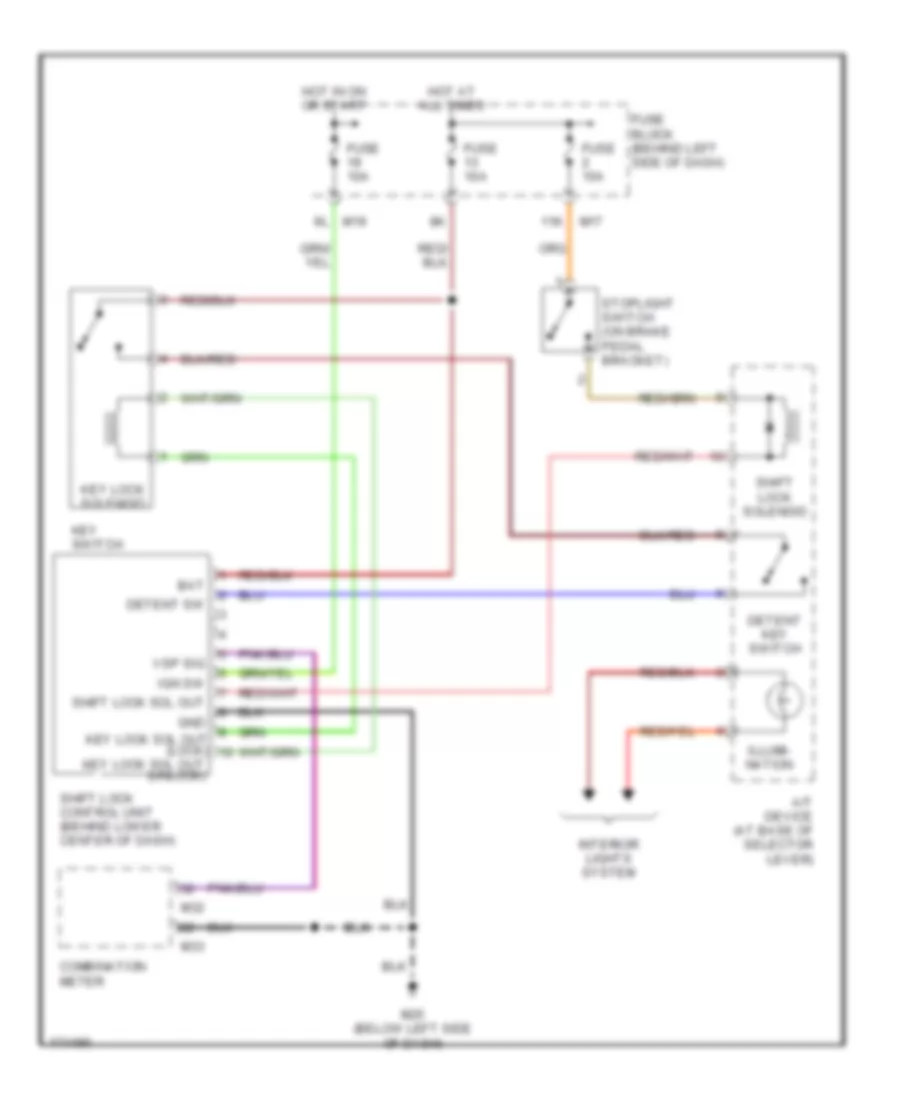
Shift Interlock Wiring Diagram for Nissan Maxima GLE 2003
List of elements for Shift Interlock Wiring Diagram for Nissan Maxima GLE 2003:
- 11k
- A/t device (at base of selector lever)
- Bat
- Combination meter
- Detent key switch
- Detent sw
- Fuse 10a
- Fuse 15a
- Fuse block (behind left side of dash)
- Gnd
- Hot at all times
- Hot in on or start
- Ign sw
- Illumi- nation
- Interior lights system
- Key lock sol out (lock)
- Key lock sol out (unlock)
- Key lock solenoid
- Key switch
- M17
- M19
- M25 (below left side of dash)
- M32
- M33
- Shift lock control unit (behind lower center of dash)
- Shift lock sol out
- Shift lock solenoid
- Stoplight switch (on brake pedal bracket)
- Vsp sig
STARTING/CHARGING
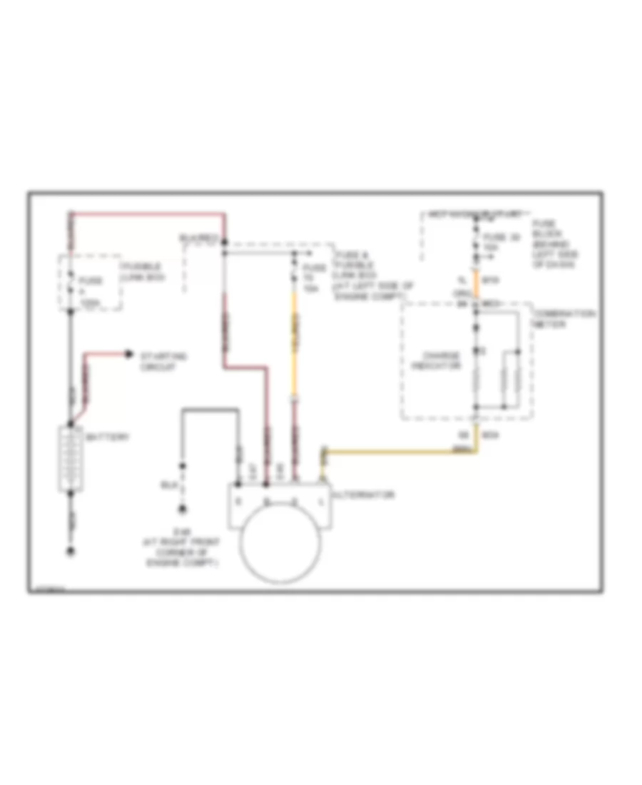
Charging Wiring Diagram for Nissan Maxima GLE 2003
List of elements for Charging Wiring Diagram for Nissan Maxima GLE 2003:
- Alternator
- Battery
- Charge indicator
- Combination meter
- E46
- E47
- E48 (at right front corner of engine compt)
- Fuse & fusible link box (at left side of engine compt)
- Fuse 10a
- Fuse 30 10a
- Fuse a 120a
- Fuse block (behind left side of dash)
- Fusible link box
- Hot in on or start
- M19
- M33
- M34
- Nca
- Starting circuit
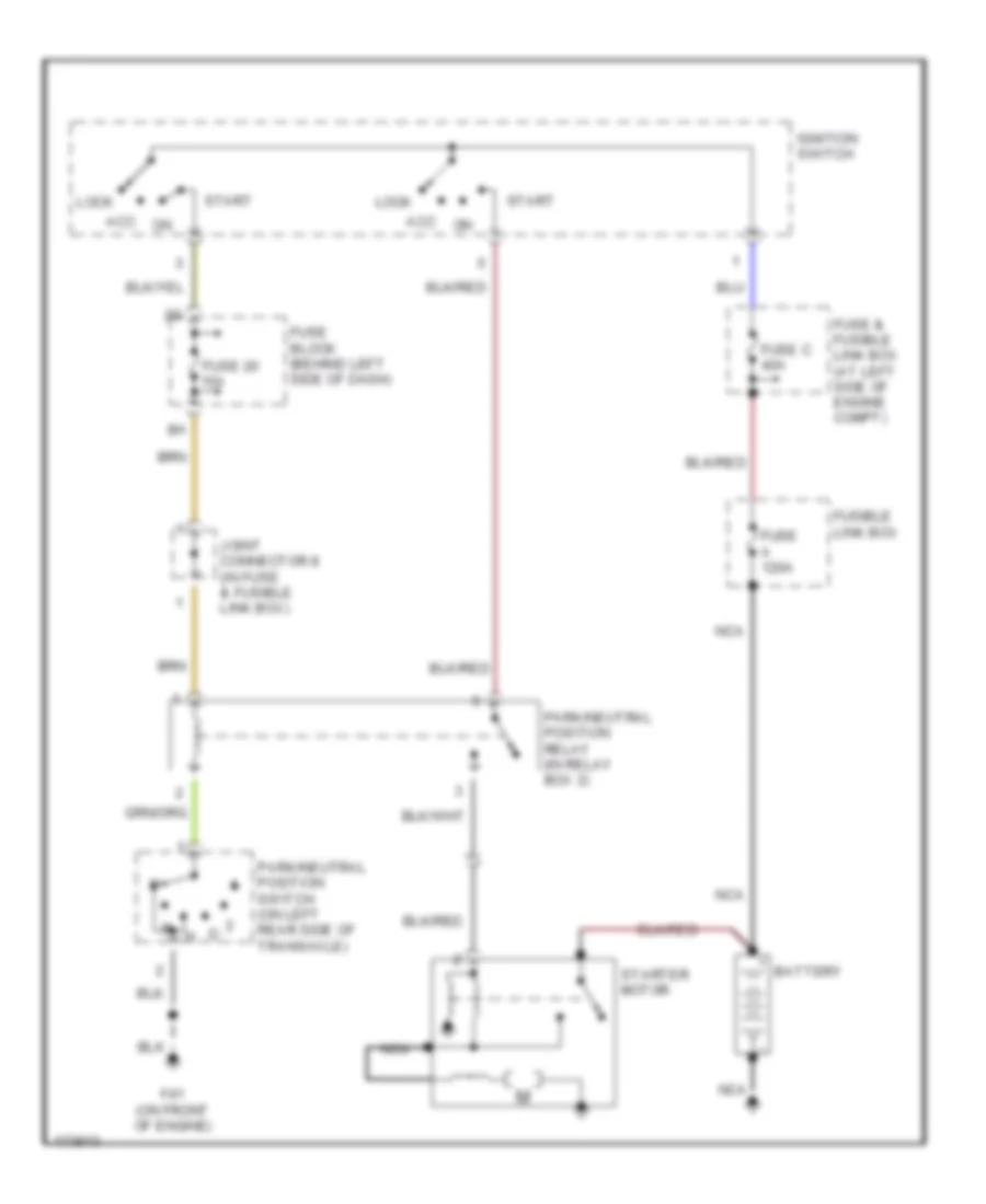
Starting Wiring Diagram, A/T for Nissan Maxima GLE 2003
List of elements for Starting Wiring Diagram, A/T for Nissan Maxima GLE 2003:
- Acc
- Battery
- F41 (on front of engine)
- Fuse & fusible link box (at left side of engine compt)
- Fuse 20 15a
- Fuse a 120a
- Fuse block (behind left side of dash)
- Fuse c 40a
- Fusible link box
- Ignition switch
- Joint connector 8 (in fuse & fusible link box)
- Lock
- Nca
- Park/neutral position relay (in relay box 2)
- Park/neutral position switch (on left rear side of transaxle)
- Start
- Starter motor
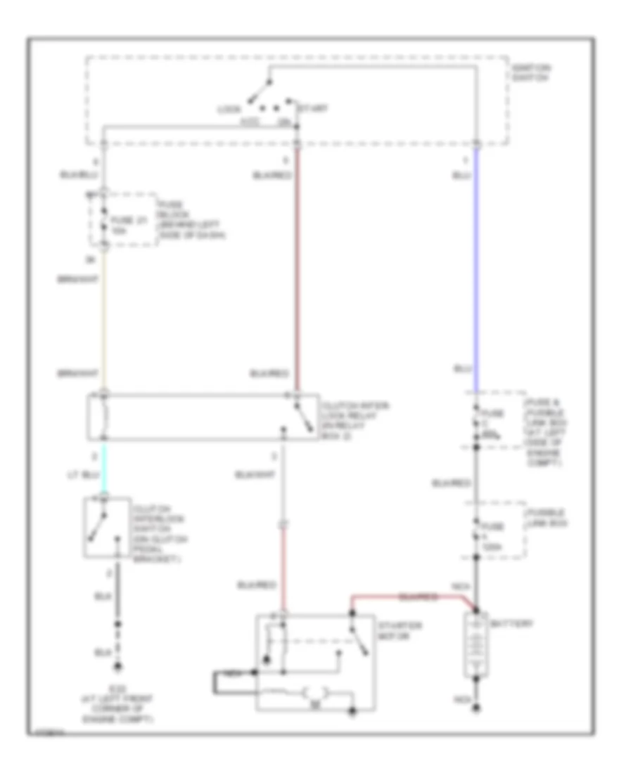
Starting Wiring Diagram, M/T for Nissan Maxima GLE 2003
List of elements for Starting Wiring Diagram, M/T for Nissan Maxima GLE 2003:
- Acc
- Battery
- Clutch inter- lock relay (in relay box 2)
- Clutch interlock switch (on clutch pedal bracket)
- E22 (at left front corner of engine compt)
- Fuse & fusible link box (at left side of engine compt)
- Fuse 21 10a
- Fuse a 120a
- Fuse block (behind left side of dash)
- Fuse c 40a
- Fusible link box
- Ignition switch
- Lock
- Nca
- Start
- Starter motor
SUPPLEMENTAL RESTRAINTS
Supplemental Restraints Wiring Diagram for Nissan Maxima GLE 2003
List of elements for Supplemental Restraints Wiring Diagram for Nissan Maxima GLE 2003:
- (at center front of engine compartment) e149
- (at center of right "a" pillar) m87
- (at left "c" pillar) b12
- (at right "b" pillar) b127
- Air bag
- Air bag diagnosis sensor unit (under rear of floor center console)
- Air bag w/l
- As1 +
- As1 -
- As2 +
- As2 -
- B135
- B42
- Combination meter
- Combination switch (spiral cable)
- Crash zone sensor
- Data link connector (dlc) (partial) (below left side of dash)
- Dr -
- Dr1 +
- Dr2 +
- Driver air bag module
- Eczs +
- Eczs -
- Eczs gnd
- Fastened
- Fuse 10a
- Fuse block (j/b) (behind left side of dash)
- Gnd
- Hot in on or start
- Ignition
- K-line
- Left satellite sensor (if equipped) (at base of left "b" pillar)
- Left seat belt buckle switch (in left seat belt buckle)
- Left seat belt pre-tensioner
- Left side air bag module (if equipped)
- M146
- M32
- M33
- M87 (at center of right "a" pillar)
- Nca
- Nca (at left "b" pillar) b44
- Nca (at right "b" pillar) b128
- Passenger air bag module
- Plh +
- Plh -
- Pnk
- Prh +
- Prh -
- Red
- Right satellite sensor (if equipped) (at base of right "b" pillar)
- Right seat belt buckle switch (in right seat belt buckle)
- Right seat belt pre-tensioner
- Right side air bag module (if equipped)
- Sat lh +
- Sat lh -
- Sat lh gnd
- Sat rh +
- Sat rh -
- Sat rh gnd
- Slh +
- Slh -
- Srh +
- Srh -
- Switch input
- Un- fastened
TRANSMISSION
Transmission Wiring Diagram for Nissan Maxima GLE 2003
List of elements for Transmission Wiring Diagram for Nissan Maxima GLE 2003:
- (left rear side of transaxle) park/neutral position switch
- (near air cleaner box) dropping resistor
- 1 pos
- 10k
- 11k
- 2 pos
- 3 pos
- A/t check ind
- A/t chk
- A/t device (3rd position switch)
- A/t fluid temp sensor
- Abs actuator & electric unit (left rear corner of engine compt)
- Abs/tcs control unit (left rear corner of engine compt)
- Accelerator pedal position sensor (above accelerator pedal)
- Aps 1
- Automatic transaxle
- Avcc
- Brk sw
- Can-h
- Can-l
- Combination meter
- D pos
- Data link connector (below)
- Duty sol
- Ect
- Engine control module (ecm) (behind lower center of dash)
- Engine coolant temperature sensor (left rear of engine)
- Exterior lights system
- F42 (front of engine)
- Fuse 10a
- Fuse 15a
- Fuse block (behind left side of dash)
- Gnd
- Gnd sens
- Gnd-a
- Hot at all times
- Hot in on or start
- J/c 20 (behind center of dash)
- J/c 3 (behind left side of dash)
- Left side of dash)
- Line press sol valve
- Lu duty
- M25 (below left side of dash)
- Mem b/u
- Nca
- Oil temp
- Over- run clutch sol
- Ovr/c
- P/n pos
- P/t sens
- Pnk
- Powertrain revolution sensor (right rear of transaxle)
- Pwr
- R pos
- Red
- Revolution sensor (top right rear of transaxle)
- Shift sol valve a
- Shift sol valve b
- Ssa
- Ssb
- Starting/ charging system
- Stoplamp switch (on brake pedal bracket)
- Tach
- Tacho
- Tcc sol valve
- Th/sen
- Transmission control module (tcm) (below lower center of dash)
- Tvo0
- V sens
- Vign
- Vss in
- Vss out
- Vss-1
- Vss-2
- W/ traction control
- W/o traction control
TRUNK, TAILGATE, FUEL DOOR
Trunk & Fuel Door Release Wiring Diagram for Nissan Maxima GLE 2003
List of elements for Trunk & Fuel Door Release Wiring Diagram for Nissan Maxima GLE 2003:
- Fuel lid opener actuator
- Fuel lid opener switch
- Fuse 15a
- Fuse block (behind left side of dash)
- Gnd
- Hot at all times
- Inertia
- M143
- M144
- M145
- M18
- M25 (below left side of dash)
- M9 (at center of left ``a" pillar)
- Smart entrance control unit (behind center of dash)
- Trunk & fuel lid opener switch
- Trunk lid opener actuator
- Trunk lid opener switch
- Trunk out
- Trunk switch
WARNING SYSTEMS
Warning Systems Wiring Diagram for Nissan Maxima GLE 2003
List of elements for Warning Systems Wiring Diagram for Nissan Maxima GLE 2003:
- (at left "b" pillar)
- 12l
- 1st
- 2nd
- A/t
- Auto
- B12 (at left ``c" pillar)
- B59 (w/ automatic drive
- B7 (w/o automatic drive
- Bat (fuse)
- Combination meter
- Combination switch (lighting switch)
- Door
- Door sw (dr)
- E22 (at left front corner of engine compartment)
- Fuse & fusible link box (at left side of engine compartment)
- Fuse 10a
- Fuse 60 10a
- Fuse block (behind left side of dash)
- Gnd
- Hot at all times
- Hot in on or start
- Ign
- Interior, exterior lights systems
- Joint connector 13 (in relay box 1)
- Key sw
- Key switch
- Lamp out
- Left front door switch
- Left seat belt buckle switch (in left seat belt buckle)
- M/t
- M143
- M144
- M145
- M17
- M19
- M25 (below left side of dash)
- M33
- M87 (at center of right ``a" pillar)
- Off
- Positioner)
- Seat belt
- Seat belt sw
- Smart entrance control unit (behind center of dash)
- T/l out1
- T/l out2
- T/l sw1
- T/l sw2
- Taillamp relay (in relay box 1)
WIPER/WASHER
Wiper/Washer Wiring Diagram for Nissan Maxima GLE 2003
List of elements for Wiper/Washer Wiring Diagram for Nissan Maxima GLE 2003:
- Auto stop
- Combination switch (front wiper switch)
- E11 (at left rear of engine compt)
- E22 (at left front corner of engine compt)
- E89
- Front washer motor (in washer reservoir)
- Front wiper motor (on right side of firewall)
- Fuse 25 20a
- Fuse block (behind left side of dash)
- Gnd
- High
- Hot in on or start
- Ign
- Int
- Int sw
- Int vr
- Joint connector 7 (in fuse & fusible link box)
- Low
- Mist
- Off
- Out- put
- Pnk
- Red
- Variable intermittent wiper volume
- Wash
- Wash sw

 Čeština
 Dansk
Dansk Deutsch
 Ελληνικά
 English
 Español
 Suomi
Suomi Français
 Français
 עברית
עברית Hrvatski
 Magyar
 Italiano
 日本語
日本語 한국어
한국어 Nederlands
 Polski
 Português
 Português
 Română
 Русский
 Slovenčina
 Slovenščina
 Svenska
 Türkçe
 中文 (中国)