AIR CONDITIONING
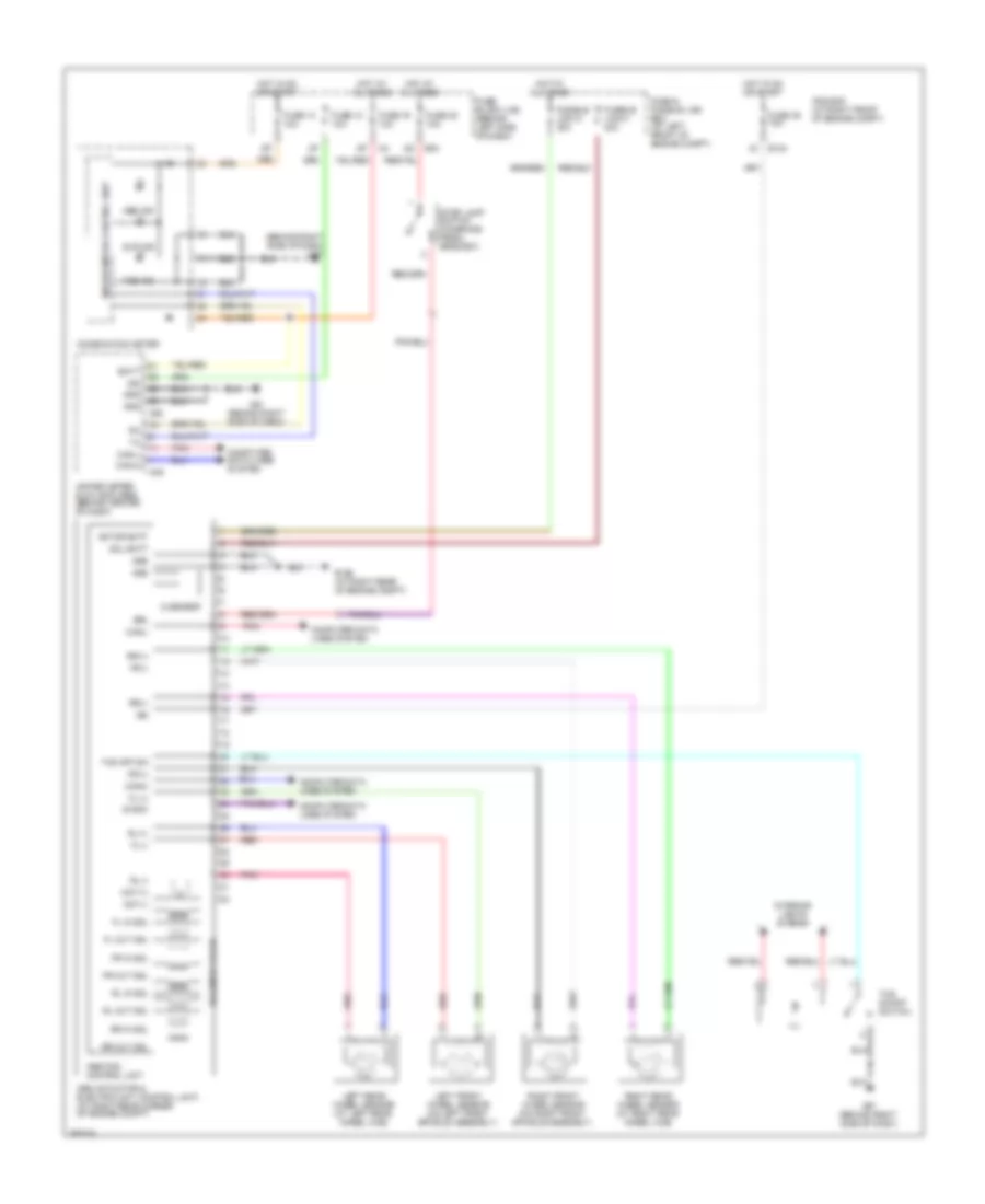
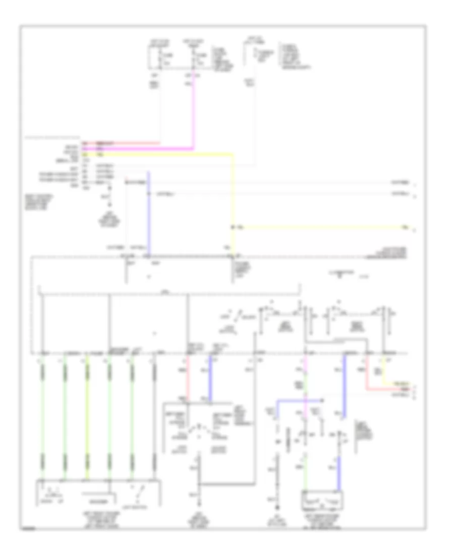
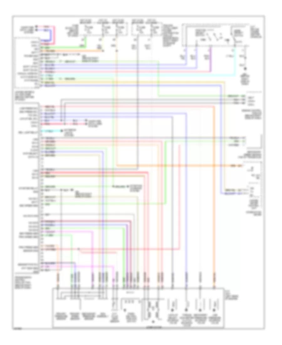
Automatic A/C Wiring Diagram (1 of 2) for Nissan Maxima SL 2008
 https://portal-diagnostov.com/license.html
Automotive Electricians Portal FZCO
Automotive Electricians Portal FZCO
https://portal-diagnostov.com/license.html
https://portal-diagnostov.com/license.html
Automotive Electricians Portal FZCO
Automotive Electricians Portal FZCO
List of elements for Automatic A/C Wiring Diagram (1 of 2) for Nissan Maxima SL 2008:
- (behind right side of dash) m57
- 8n m3
- 8p/r
- Acc
- Amb sens
- Ambient sensor (at left front corner of vehicle)
- Bat
- Blower motor (behind right side of dash)
- Can-h
- Can-l
- Combination meter
- Comp on
- Computer data lines system
- Display control unit (behind center of dash)
- Driver side air mix door motor (behind center of dash)
- Fan control amplifier (behind right side of dash)
- Fan f/b
- Fan gate
- Fan on
- Fuse 10a
- Fuse 15a
- Fuse block (j/b) (behind left side of dash)
- Gnd
- Hot at all times
- Hot in on
- Hot in on or acc
- Hot in on or start
- Ign
- Ign 2
- In-vehicle sensor (behind center of dash)
- Incar sens
- Intake door motor (behind right side of dash)
- Intake sens
- Intake sensor (behind right side of dash)
- Lan sig
- M24
- M4 12p
- M49
- M50
- M57 (behind right side of dash)
- M89
- Mode door motor (behind center of dash)
- Passenger side air mix door motor (behind right side of dash)
- Pnk
- Rrdef sw
- Sens gnd
- Solid state
- Speed (8p)
- Sun sens
- Sunload sensor (on right defroster grille)
- Unified meter & a/c amplifier (behind center of dash)
- Unified meter control unit
- Vactr
- W/ navigation
- W/o navigation
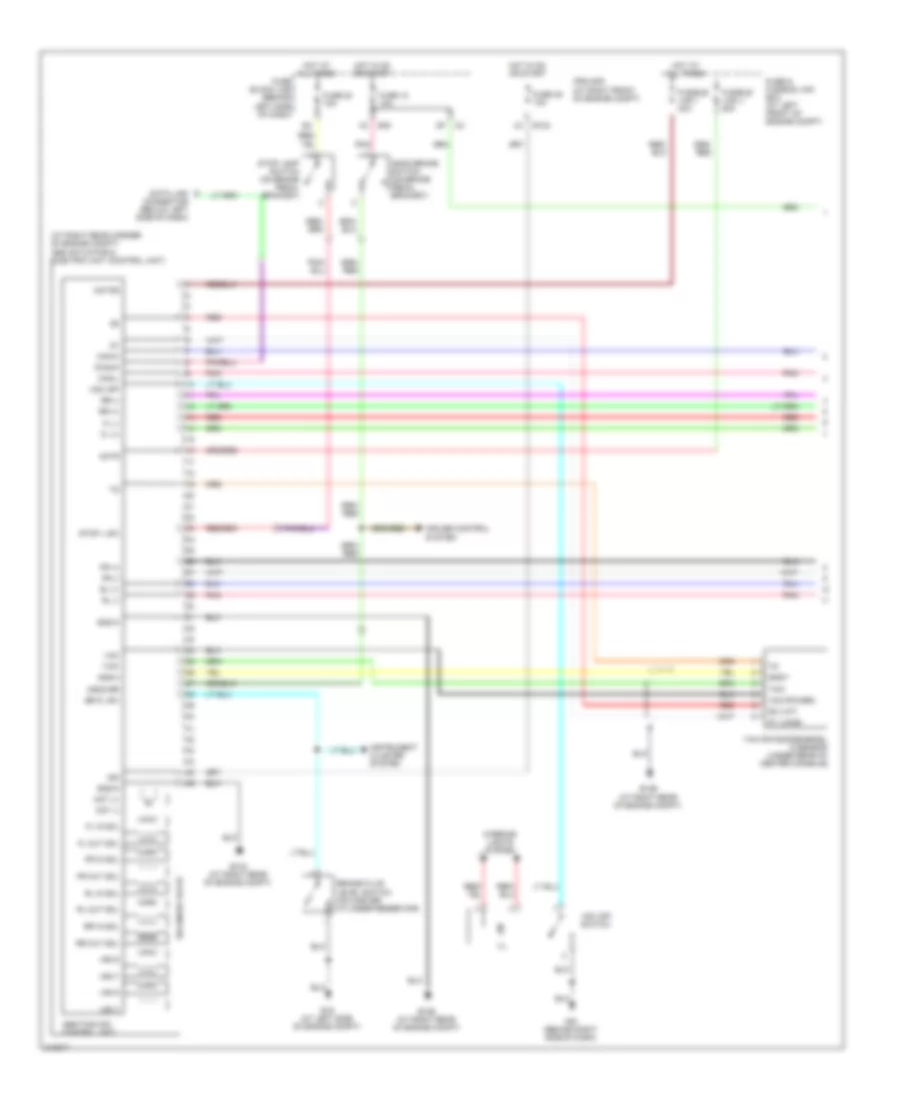
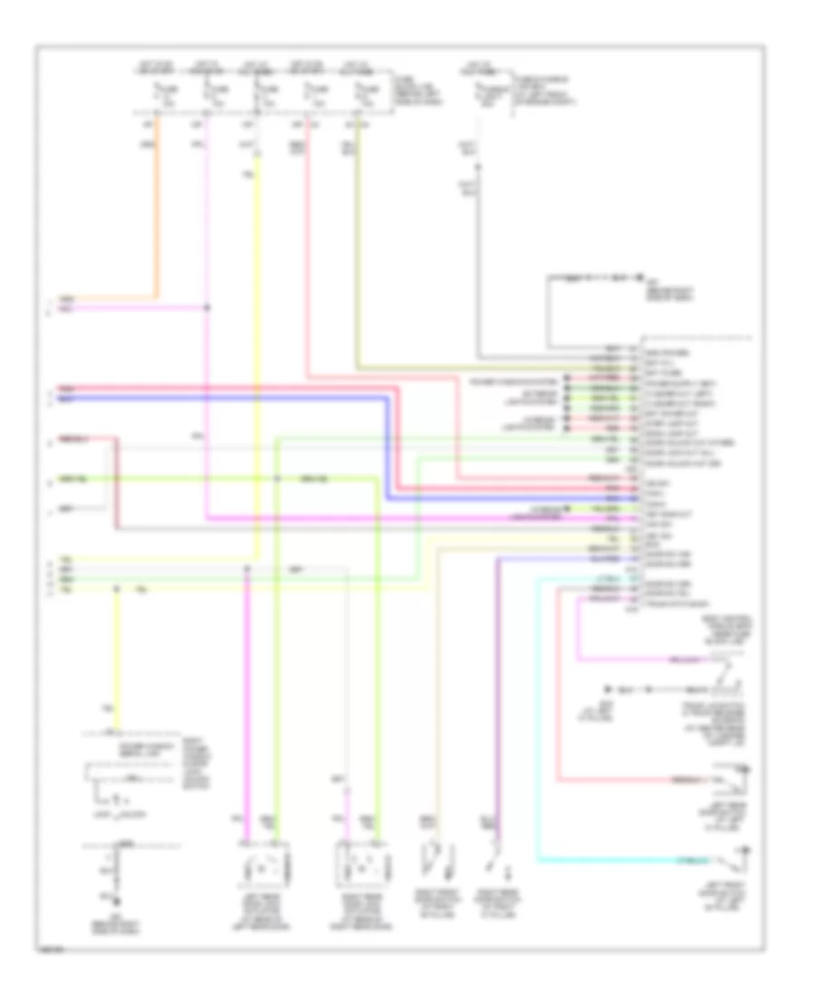
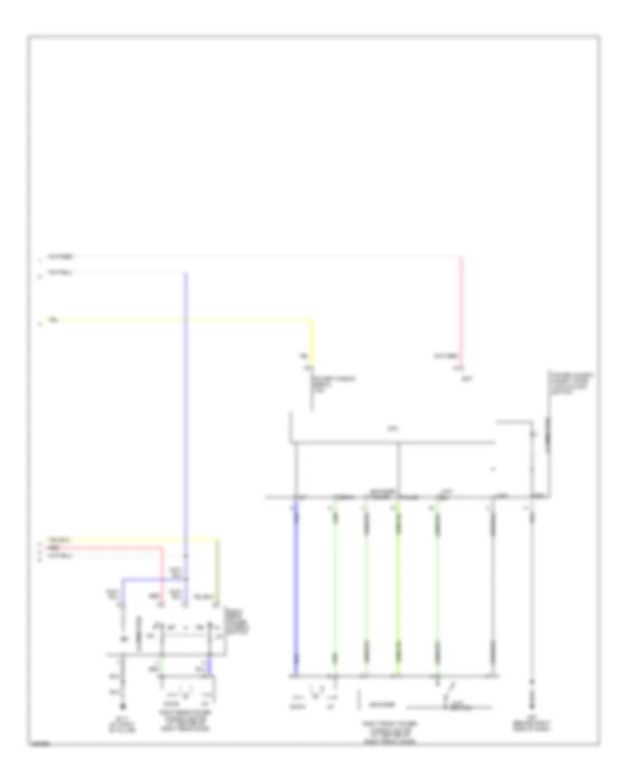
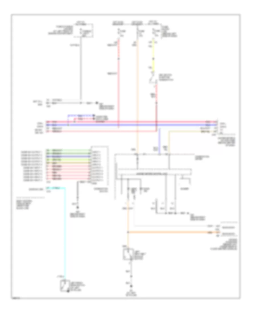
Automatic A/C Wiring Diagram (2 of 2) for Nissan Maxima SL 2008
List of elements for Automatic A/C Wiring Diagram (2 of 2) for Nissan Maxima SL 2008:
- (at left front of engine)
- +ig
- A/c compressor
- A/c relay
- Avcc
- Body control module (bcm) (near fuse block (j/b))
- Can-h
- Can-l
- Comp on
- Cooling fan motor 1 (at front of engine compt)
- Cooling fan motor 2 (at front of engine compt)
- Cooling fan relay 1
- Cooling fan relay 2
- Cooling fan relay 3
- Cpu
- E10
- E118
- E120
- E121
- E123
- E124
- E15 (at left side of engine compt)
- Ecm (behind right side of dash)
- Engine coolant temperature sensor (on left rear of engine)
- F54
- Fan on
- Fuse & fusible link box (at left front of engine compt)
- Fuse 10a
- Fusible link b 80a
- Fusible link box (battery)
- Fusible link k 40a
- Fusible link l 40a
- Gnd (pwr)
- Gnd (sig)
- Gnd-a
- Hot at all times
- Hot in on or start
- Ignition relay
- Ipdm e/r (at right front of engine compt)
- M18
- M82
- Motor fan-1
- Motor fan-2
- Motor fan-3
- Pdpress
- Pnk
- Red
- Refrigerant pressure sensor (on a/c liquid tank)
- Rrdef sw
ANTI-LOCK BRAKES
Anti-lock Brakes Wiring Diagram, with Traction Control for Nissan Maxima SL 2008
List of elements for Anti-lock Brakes Wiring Diagram, with Traction Control for Nissan Maxima SL 2008:
- (behind right side of dash) m57
- Abs actuator & electric unit (control unit) (at right rear corner of engine compt)
- Abs ind
- Abs/tcs control unit
- Batt
- Brl
- Can-h
- Can-l
- Combination meter
- Computer data lines system
- Diag-k
- E124
- E126 (at right rear of engine compt)
- E30
- Fl (+)
- Fl (-)
- Fl in sol
- Fl out sol
- Fr (+)
- Fr (-)
- Fr in sol
- Fr out sol
- Fuse & fusible link box (at left front of engine compt)
- Fuse 12 10a
- Fuse 14 10a
- Fuse 19 10a
- Fuse 20 10a
- Fuse 49 10a
- Fuse block (j/b) (behind left side of dash)
- Fusible link g 30a
- Fusible link h 30a
- G sensor
- Gnd
- Hot at all times
- Hot in on or start
- Ign
- Ill
- Interior lights system
- Ipdm e/r (at right front of engine compt)
- Left front wheel sensor (on left front spindle assembly)
- Left rear wheel sensor (at left rear wheel hub)
- M49
- M50
- M57 (behind right side of dash)
- M61 (behind right side of dash)
- Mot (+)
- Mot (-)
- Motor batt
- Pnk
- Red
- Right front wheel sensor (on right front spindle assembly)
- Right rear wheel sensor (at right rear wheel hub)
- Rl (+)
- Rl (-)
- Rl in sol
- Rl out sol
- Rr (+)
- Rr (-)
- Rr in sol
- Rr out sol
- Slip ind
- Sol batt
- Solenoid valve
- Stop lamp switch (on brake pedal bracket)
- Tcs ind
- Tcs off sw
- Tcs on/off switch
- Unified meter & a/c amplifier (behind center of dash)
- Unified meter control unit
Anti-lock Brakes Wiring Diagram, without Traction Control & Stability Assist (1 of 2) for Nissan Maxima SL 2008
List of elements for Anti-lock Brakes Wiring Diagram, without Traction Control & Stability Assist (1 of 2) for Nissan Maxima SL 2008:
- (at right rear corner of engine compt) abs actuator & electric unit (control unit)
- Abs/tcs/vdc control unit
- Actr
- Ascd br
- Ascd brake switch (on brake pedal bracket)
- Br fl sw
- Brake fluid level switch (on master cylinder reservoir)
- Can-h
- Can-l
- Cruise control system
- Data link connector (below left side of dash)
- Diag-k
- E124
- E126 (at right rear of engine compt)
- E133 (at right rear of engine compt)
- E15 (at left side of engine compt)
- E30
- Fl (+)
- Fl (-)
- Fl in sol
- Fl out sol
- Fr (+)
- Fr (-)
- Fr in sol
- Fr out sol
- Fuse & fusible link box (at left front of engine compt)
- Fuse 12 10a
- Fuse 20 10a
- Fuse 49 10a
- Fuse block (j/b) (behind left side of dash)
- Fusible link i 40a
- Fusible link j 50a
- G1 (long)
- G2 (lat)
- Gnd-4
- Gnd-a
- Gnd-m
- Gnd-y
- Hot at all times
- Hot in on or start
- Hsv1
- Hsv2
- Ign
- Ill
- Instrument cluster system
- Interior lights system
- Ipdm e/r (at right front of engine compt)
- M61 (behind right side of dash)
- Mot (+)
- Mot (-)
- Motor
- Pnk
- Red
- Rl (+)
- Rl (-)
- Rl in sol
- Rl out sol
- Rr (+)
- Rr (-)
- Rr in sol
- Rr out sol
- Solenoid valve
- Stop l sw
- Stop lamp switch (on brake pedal bracket)
- Usv1
- Usv2
- Vcc
- Vcc (power)
- Vdc off
- Vdc off switch
- Yaw
- Yaw rate/side/decel g sensor (under rear of center console)
Anti-lock Brakes Wiring Diagram, without Traction Control & Stability Assist (2 of 2) for Nissan Maxima SL 2008
List of elements for Anti-lock Brakes Wiring Diagram, without Traction Control & Stability Assist (2 of 2) for Nissan Maxima SL 2008:
- Abs ind
- Batt
- Can-h
- Can-l
- Combination meter
- Computer data lines system
- Fuse 14 10a
- Fuse 19 10a
- Fuse block (j/b) (behind left side of dash)
- Gnd
- Hot at all times
- Hot in on or start
- Ign
- Left front wheel sensor (on left front spindle assembly)
- Left rear wheel sensor (at left rear wheel hub)
- M49
- M50
- M57 (behind right side of dash)
- M61 (behind right side of dash)
- Pnk
- Red
- Right front wheel sensor (on right front spindle assembly)
- Right rear wheel sensor (at right rear wheel hub)
- Slip ind
- Steering angle sensor (on steering column)
- Unified meter & a/c amplifier (behind center of dash)
- Unified meter control unit
- Vdc off ind
ANTI-THEFT
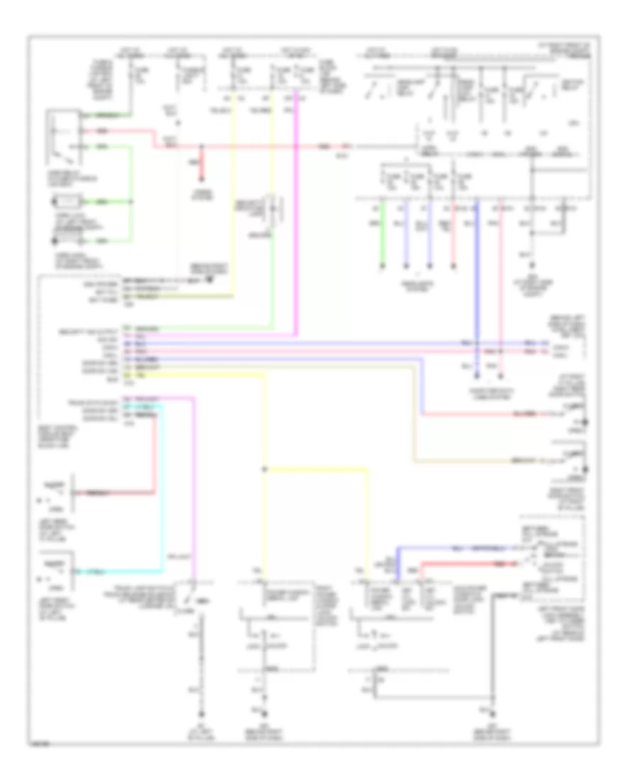
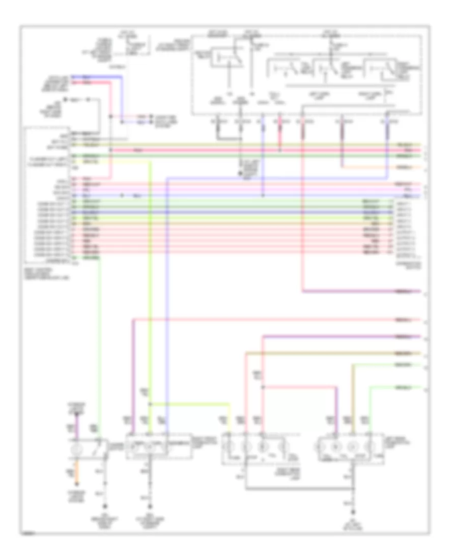
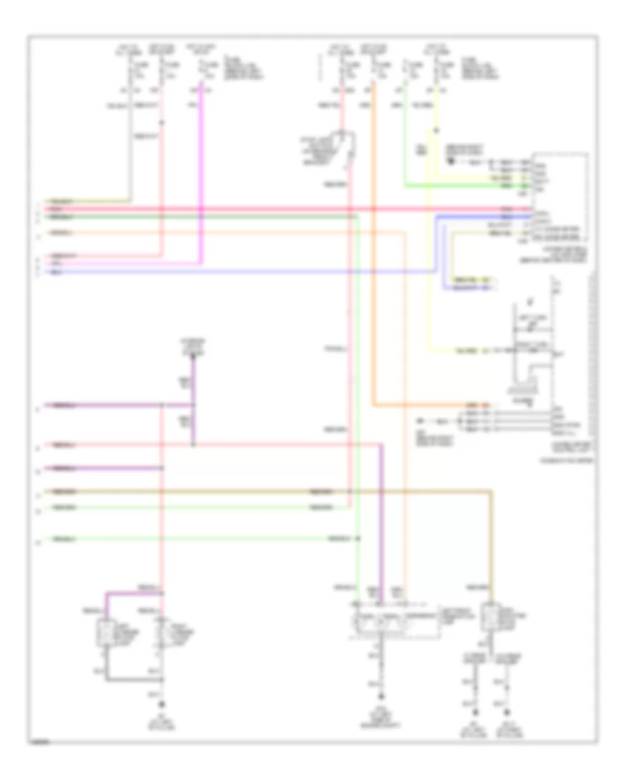
Forced Entry Wiring Diagram for Nissan Maxima SL 2008
List of elements for Forced Entry Wiring Diagram for Nissan Maxima SL 2008:
- (at right "c" pillar) right rear door switch
- (at right front of engine compt) ipdm e/r
- (behind left side of dash) intelligent key unit
- (behind right side of dash) m57
- +ig
- 12p m4
- Acc sw
- B7 (at left "b" pillar)
- Bat (f/l)
- Bat (fuse)
- Between full stroke & n
- Body control module (bcm) (near fuse block (j/b))
- Bus
- Can-h
- Can-l
- Close
- Closed
- Computer data lines system
- Cpu
- Door sw (as)
- Door sw (dr)
- Door sw (rl)
- Door sw (rr)
- E121
- E122
- E124
- E24 (at right side of engine compt)
- Full stroke
- Full stroke lock switch
- Fuse & fusible link box (at left front of engine compt)
- Fuse 10a
- Fuse 15a
- Fuse block (j/b) (behind left side of dash)
- Fusible link f 50a
- Gnd
- Gnd (power)
- Gnd (signal)
- H/lp hi
- H/lp lo
- Head- lamp low relay
- Headlamp high relay
- Headlights system
- Horn (high) (at right front of engine compt)
- Horn (low) (at left front of engine compt)
- Horn relay
- Horn relay (in fuse & fusible link box)
- Horns system
- Hot at all times
- Hot in acc or on
- Hot in on or start
- Ignition relay
- Key cyl lock sw
- Key cyl unlock sw
- Left front door lock assembly (key cylinder switch) (at rear of left front door)
- Left front door switch (at left "b" pillar)
- Left rear door switch (at left "c" pillar)
- Lock
- M18
- M19
- M20
- M57 (behind right side of dash)
- M61 (behind right side of dash)
- Main power window & door lock/ unlock switch
- Open
- Pnk
- Power window serial link
- Red
- Right front door switch (at right "b" pillar)
- Right power window & door lock/ unlock switch
- Security ind output
- Security indicator lamp
- Trunk lamp switch & trunk release solenoid (at rear center of luggage lid)
- Trunk status sw
- Unlock
- Unlock switch
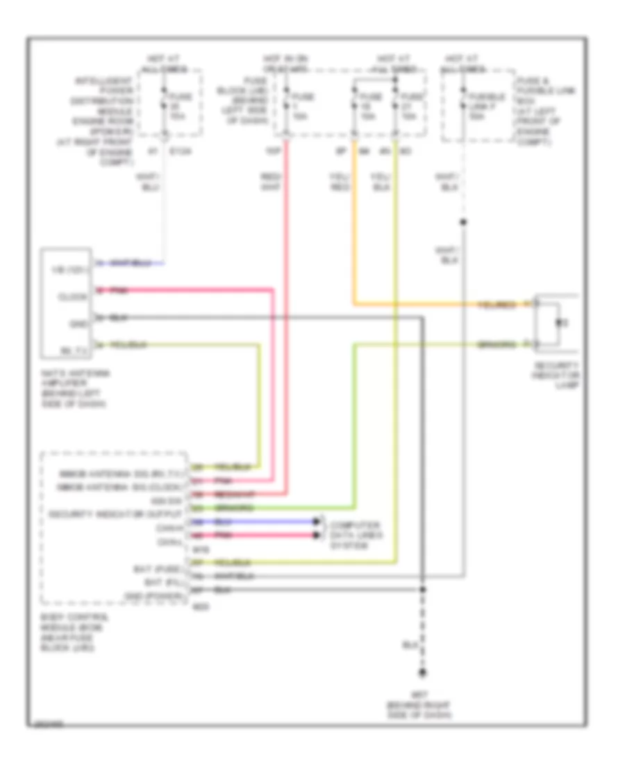
Immobilizer Wiring Diagram for Nissan Maxima SL 2008
List of elements for Immobilizer Wiring Diagram for Nissan Maxima SL 2008:
- 15p
- 4n m3
- Bat (f/l)
- Bat (fuse)
- Body control module (bcm) (near fuse block (j/b))
- Can-h
- Can-l
- Clock
- Computer data lines system
- E124
- Fuse & fusible link box (at left front of engine compt)
- Fuse 10a
- Fuse 15a
- Fuse block (j/b) (behind left side of dash)
- Fusible link f 50a
- Gnd
- Gnd (power)
- Hot at all times
- Hot in on or start
- Ign sw
- Immob antenna sig (clock)
- Immob antenna sig (rx,tx)
- Intelligent power distribution module engine room (ipdm e/r) (at right front of engine compt)
- M18
- M20
- M57 (behind right side of dash)
- Nats antenna amplifier (behind left side of dash)
- Pnk
- Rx,tx
- Security indicator lamp
- Security indicator output
- Vb (12v)
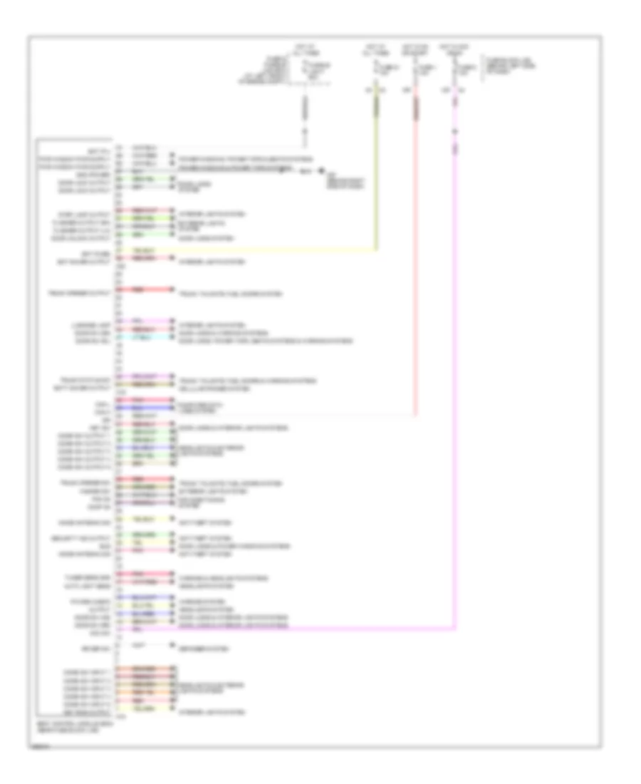
BODY CONTROL MODULES
Body Control Modules Wiring Diagram for Nissan Maxima SL 2008
List of elements for Body Control Modules Wiring Diagram for Nissan Maxima SL 2008:
- 12p
- 15p
- Acc sw
- Air conditioning system
- Anti-theft system
- Auto light sens
- Bat (f/l)
- Bat (fuse)
- Bat saver output
- Batt saver output
- Body control module (bcm) (near fuse block (j/b))
- Bus
- Can h
- Can l
- Cellular phones system
- Combi sw input 1
- Combi sw input 2
- Combi sw input 3
- Combi sw input 4
- Combi sw input 5
- Combi sw output 1
- Combi sw output 2
- Combi sw output 3
- Combi sw output 4
- Combi sw output 5
- Comp on
- Computer data lines system
- Defogger system
- Door lock output
- Door locks & interior lights systems
- Door locks & power windows systems
- Door locks & warning systems
- Door locks system
- Door locks, power tops, seats systems & warning systems
- Door sw (as)
- Door sw (dr)
- Door sw (rl)
- Door sw (rr)
- Door unlock output
- Exterior lights system
- Fan on
- Flasher output (lh)
- Flasher output (rh)
- Fuse & fusible link box (at left front of engine compt)
- Fuse 1 10a
- Fuse 21 10a
- Fuse 6 10a
- Fuse block (j/b) (behind left side of dash)
- Fusible link f 50a
- Gnd (power)
- Hazard sw
- Headlights & exterior lights systems
- Headlights system
- Hot at all times
- Hot in acc or on
- Hot in on or start
- Ign
- Immob antenna sig
- Interior lights system
- Key ring output
- Key sw
- Luggage lamp
- M18
- M19
- M20
- M57 (behind right side of dash)
- Output
- P/warn check
- Pnk
- Power windows & power tops systems
- Power windows, power tops & seats systems
- Red
- Rr def sw
- Security ind output
- Step lamp output
- Trunk opener output
- Trunk opener sw
- Trunk status sw
- Trunk, tailgate, fuel doors & warning systems
- Trunk, tailgate, fuel doors system
- Tuner sens gnd
- Warning & headlights systems
- Warning system
COMPUTER DATA LINES
Computer Data Lines Wiring Diagram for Nissan Maxima SL 2008
List of elements for Computer Data Lines Wiring Diagram for Nissan Maxima SL 2008:
- (behind right side of dash) m57
- Abs actuator & electric unit (control unit) (at right rear corner of engine compt)
- Abs/tcs control unit
- Air bag diagnosis sensor unit (under rear of floor center console)
- Audio unit
- Automatic drive positioner control unit (behind right center of dash)
- Av switch
- B401
- Body control module (bcm) (near fuse block (j/b))
- Bus
- Bus +
- Bus -
- Bus shield
- Can-h
- Can-l
- Combination meter
- Cpu
- Data link connector (below left side of dash)
- Diag-k
- Display control unit (w/ navigation) (behind center of dash)
- Driver seat control unit (w/ automatic driver positioner)
- E121
- Engine control module (ecm) (behind right side of dash)
- F56
- Fuse 12 10a
- Fuse 19 10a
- Fuse block (j/b) (behind left side of dash)
- Hot at all times
- Hot in on or start
- Immob antenna sig (rx,tx)
- Intelligent key unit (behind left side of dash)
- Ipdm e/r (at right front of engine compt)
- K-line
- Left rear power window switch (w/ front & rear power window anti-pinch system)
- M18
- M35
- M41
- M49
- M82
- M95
- M97
- Main power window & door lock/unlock switch
- Nats antenna amplifier (behind left side of dash)
- Navi control unit (behind center of dash)
- Nca
- Pnk
- Power window serial link
- Red
- Right power window & door lock/unlock switch
- Right rear power window switch (w/ front & rear power window anti-pinch system)
- Rx,tx
- Shield
- Steering angle sensor (w/ vdc) (on steering column)
- Transmission control module (tcm) (behind right side of dash)
- Unified meter & a/c amplifier (behind center of dash)
- Unified meter control unit
- W/ bose audio system
- W/ navigation
- W/ tcs
- W/ vdc
- W/o bose audio system
- W/o navigation
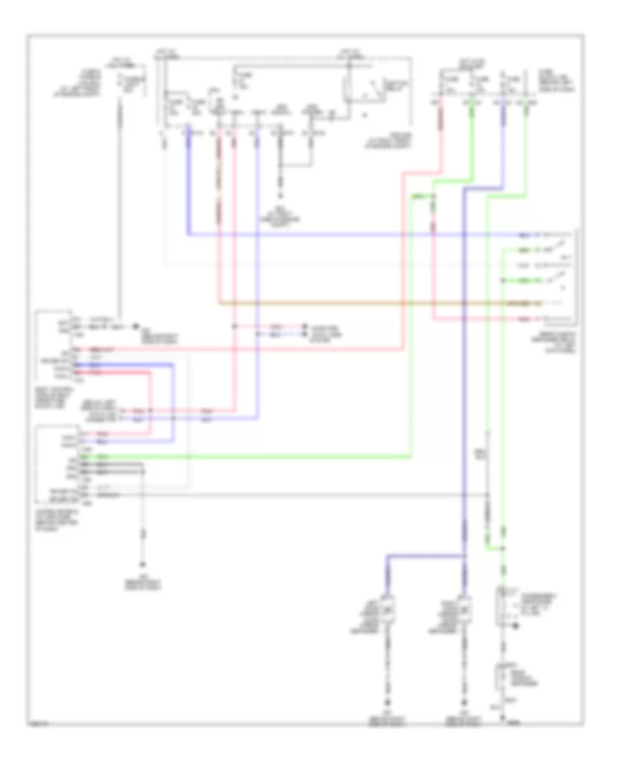
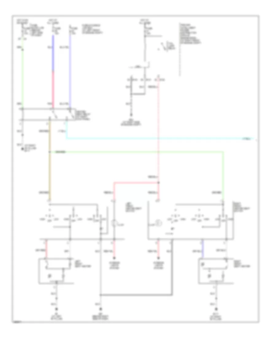
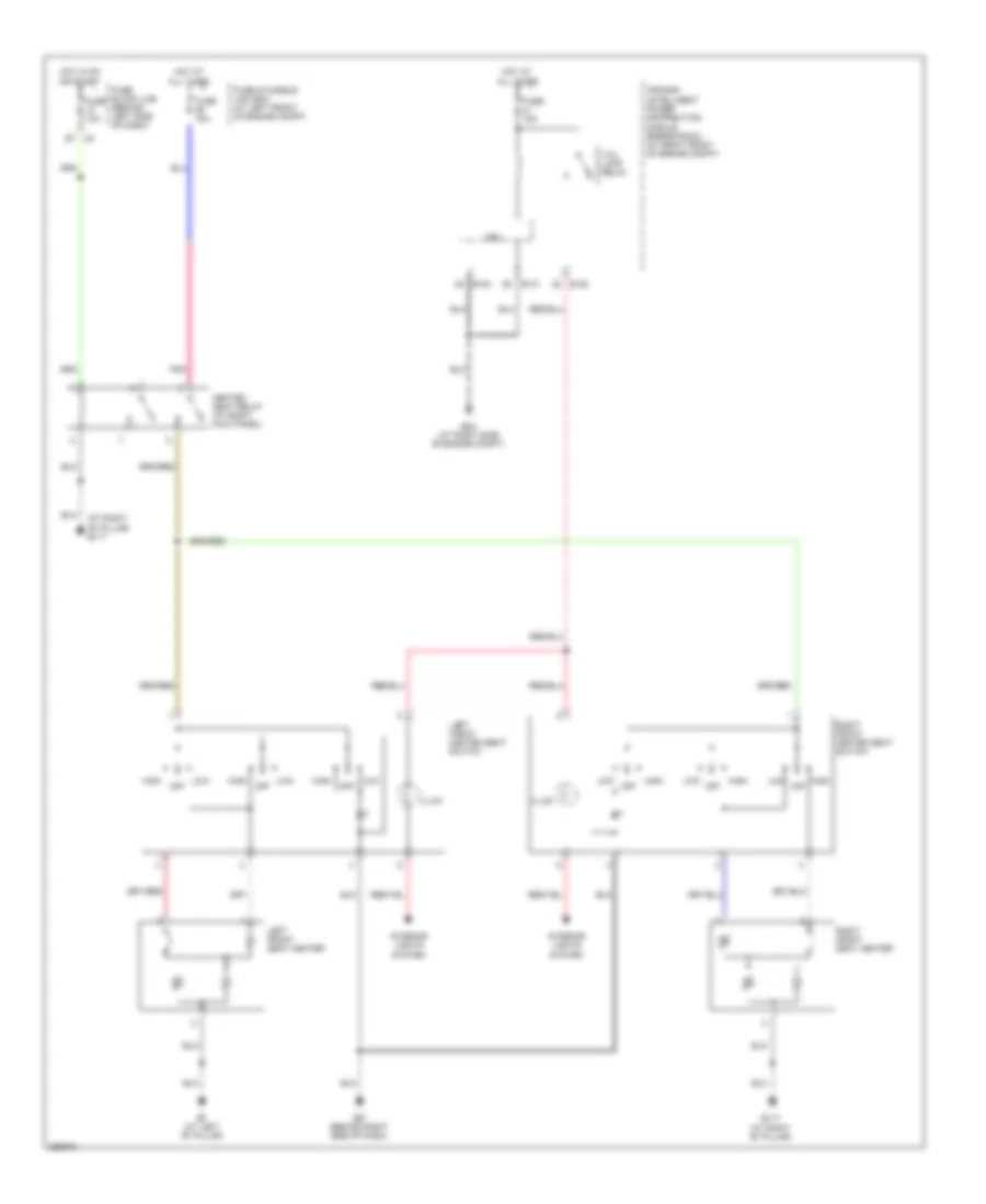
COOLING FAN
Cooling Fan Wiring Diagram for Nissan Maxima SL 2008
List of elements for Cooling Fan Wiring Diagram for Nissan Maxima SL 2008:
- (at right front of engine compt) ipdm e/r
- +ig
- Can-h
- Can-l
- Cooling fan motor 1 (at front of engine compt)
- Cooling fan motor 2 (at front of engine compt)
- Cooling fan relay 1
- Cooling fan relay 2
- Cooling fan relay 3
- Cpu
- E10
- E118
- E120
- E121
- E123
- E124
- E15 (at left side of engine compt)
- Ecm (behind right side of dash)
- Engine coolant temperature sensor (on left rear of engine)
- F54
- Fuse & fusible link box (at left front of engine compt)
- Fusible link b 80a
- Fusible link box (battery)
- Fusible link k 40a
- Fusible link l 40a
- Gnd (pwr)
- Gnd (sig)
- Gnd-a
- Hot at all times
- Hot in on or start
- Ignition relay
- M82
- Motor fan-1
- Motor fan-2
- Motor fan-3
- Pnk
- Red
- Refrigerant pressure sensor (on a/c liquid tank)
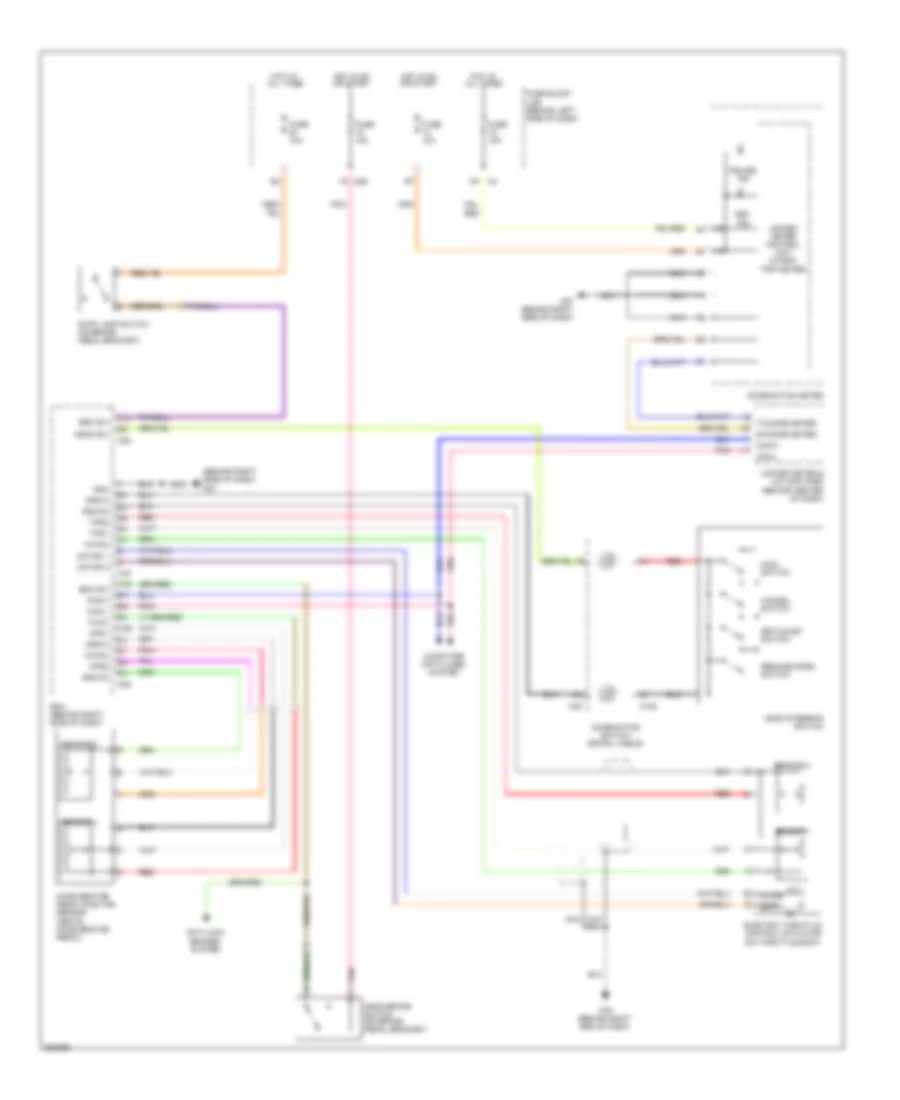
CRUISE CONTROL
Cruise Control Wiring Diagram for Nissan Maxima SL 2008
List of elements for Cruise Control Wiring Diagram for Nissan Maxima SL 2008:
- (behind right side of dash) m61
- 1q e30
- Accelerator pedal position sensor (above accelerator pedal)
- Anti-lock brakes system
- Aps1
- Aps2
- Ascd brake switch (on brake pedal bracket)
- Ascd steering switch
- Ascd sw
- Avcc
- Avcc2
- Bnc sw
- Brk sw
- Can-h
- Can-l
- Cancel switch
- Close
- Combination meter
- Combination switch (spiral cable)
- Computer data lines system
- Cruise ind
- Ecm (behind right side of dash)
- Electric throttle control actuator (on throttle body)
- F54
- Fuse 10a
- Fuse block (j/b) (behind left side of dash)
- Gnd
- Gnd-a
- Gnd-a2
- Hot at all times
- Hot in on or start
- M102
- M30
- M57 (behind right side of dash)
- M79 (behind right end of dash)
- M82
- Main switch
- Motor 1
- Motor 2
- Nca
- Open
- Pnk
- Red
- Resume/accel switch
- Rx(comb meter)
- Sensor 1
- Sensor 2
- Set ind
- Set/coast switch
- Stop lamp switch (on brake pedal bracket)
- Tps1
- Tps2
- Tx(comb meter)
- Unified meter & a/c amplifier (behind center of dash)
- Unified meter control unit (w/odo/ trip meter)
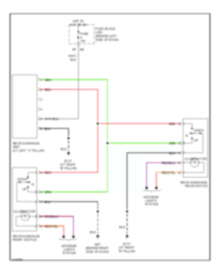
DEFOGGERS
Defoggers Wiring Diagram for Nissan Maxima SL 2008
List of elements for Defoggers Wiring Diagram for Nissan Maxima SL 2008:
- (below left side of dash) data link connector
- + b301
- +ig
- - b351
- 15p
- B352
- Bat
- Body control module (bcm) (near fuse block (j/b))
- Can-h
- Can-l
- Computer
- Condenser-3 (near base of left "c" pillar)
- Cpu
- Data lines
- E119
- E121
- E124
- E24 (at right side of engine compt)
- E30
- Fuse & fusible link box (at left front of engine compt)
- Fuse 10a
- Fuse 15a
- Fuse 20a
- Fuse block (j/b) (behind left
- Fusible link f 50a
- Gnd
- Gnd (power)
- Gnd (signal)
- Hot at all times
- Hot in on or start
- Ign
- Ignition relay
- Ipdm e/r (at right front of engine compt)
- Left door mirror (door mirror defogger)
- M18
- M20
- M49
- M50
- M57 (behind right side of dash)
- M61 (behind right side of dash)
- M89
- Pnk
- Rear window defogger
- Rear window defogger relay (at left kick panel)
- Right door mirror (door mirror defogger)
- Rr def f/b
- Rr def on
- Rr def relay
- Rr def sw
- Side of dash)
- System
- Unified meter & a/c amplifier (behind center of dash)
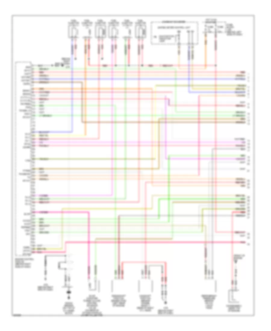
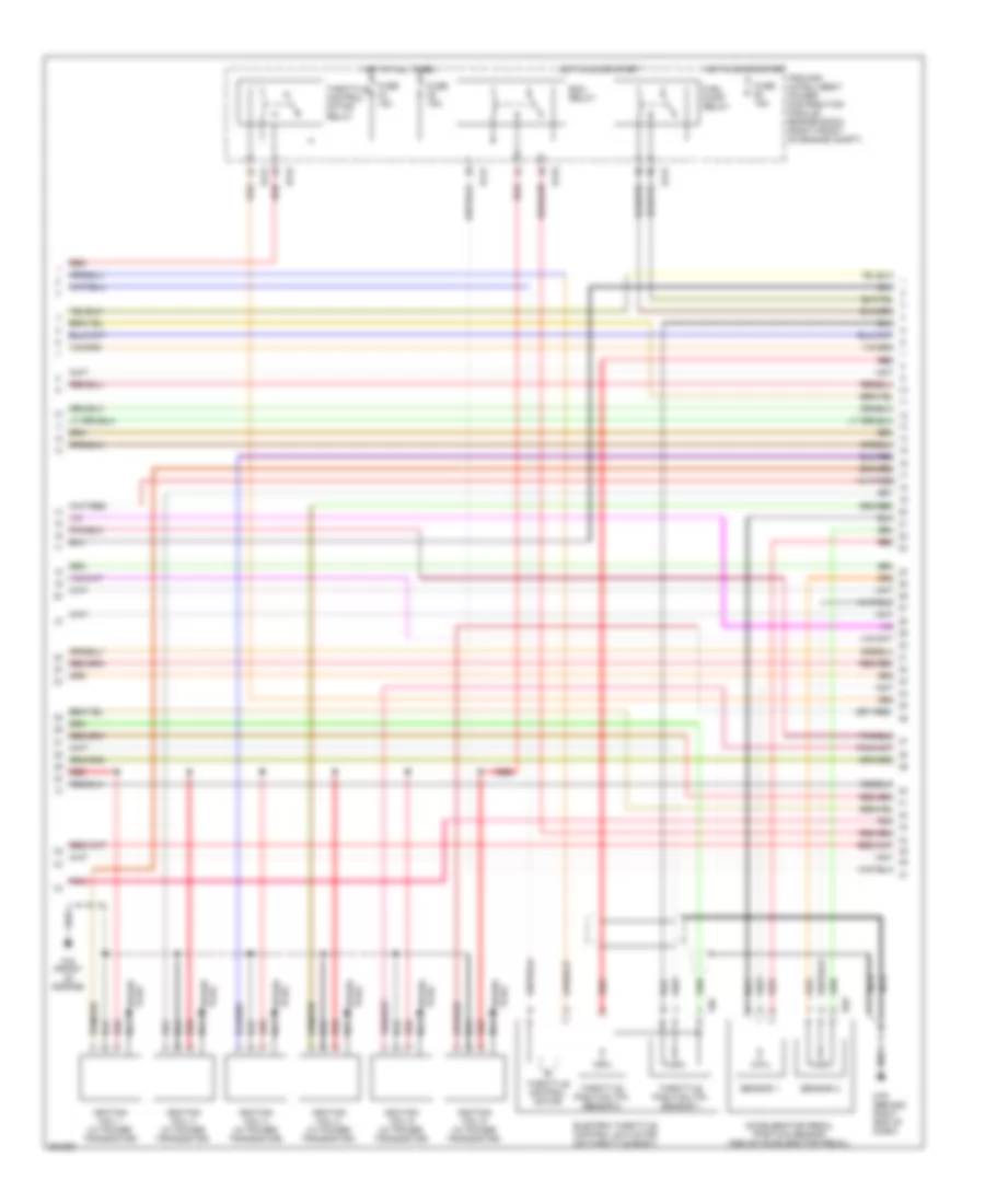
ENGINE PERFORMANCE
3.5L
3.5L, Engine Performance Wiring Diagram (1 of 4) for Nissan Maxima SL 2008
List of elements for 3.5L, Engine Performance Wiring Diagram (1 of 4) for Nissan Maxima SL 2008:
- (behind right end of dash)
- (front of engine) f16
- 15p
- A/f-ip1
- Af-h1
- Af-h2
- Af-un1
- Af-vm1
- Af-vm2
- Avcc
- Avcc2
- C-vtc (l)
- C-vtc (r)
- Camshaft position sensor (phase) (bank 1) (rear of right cyl head)
- Combination meter
- Condenser 2 (near top of engine)
- Crankshaft position sensor (pos) (left rear of engine)
- Engine control module (behind right side of dash)
- Enmn1
- Enmn2
- Evap
- Evap canister purge volume control solenoid valve (on rear of intake manifold lower collector)
- Ftprs
- Fuel injector
- Fuse 10a
- Fuse block (j/b) (behind left side of dash)
- Gnd
- Hot in on or start
- Ign
- Inj 1
- Inj 2
- Inj 3
- Inj 4
- Inj 5
- Inj 6
- Knk1
- Knock sensor (on top of cylinder block)
- M79
- M79 (behind right end of dash)
- Malfunction indicator lamp
- Motor1
- Motor2
- Nca
- O2hrl
- O2hrr
- O2srl
- Pdpres
- Phase lh
- Phase rh
- Pnk
- Pos
- Ps pres
- Qa+
- Red
- Refrigerant pressure sensor (on a/c liquid tank)
- Tps1
- Unified meter control unit
- Vias
- Vmot
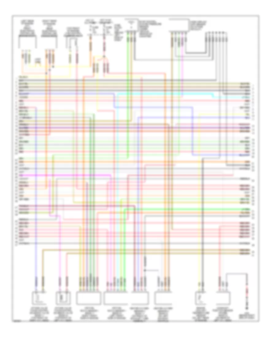
3.5L, Engine Performance Wiring Diagram (2 of 4) for Nissan Maxima SL 2008
List of elements for 3.5L, Engine Performance Wiring Diagram (2 of 4) for Nissan Maxima SL 2008:
- (behind right end of dash)
- Accelerator pedal position sensor (above accelerator pedal)
- E121
- E122
- E124
- E40
- Ecm relay
- Electric throttle control actuator (on throttle body)
- F16 (front of engine)
- F50
- Fuel pump relay
- Fuse 15a
- Hot at all times
- Hot in on or start
- Ignition coil 1 (w/ power transistor)
- Ignition coil 2 (w/ power transistor)
- Ignition coil 3 (w/ power transistor)
- Ignition coil 4 (w/ power transistor)
- Ignition coil 5 (w/ power transistor)
- Ignition coil 6 (w/ power transistor)
- Ipdm e/r (intelligent power distribution module engine room) (right front of engine compt)
- M79
- Nca
- Plug spark
- Pnk
- Red
- Sensor 1
- Sensor 2
- Spark plug
- Throttle control motor
- Throttle control motor relay
- Throttle position (tp) sensor 1
- Throttle position (tp) sensor 2
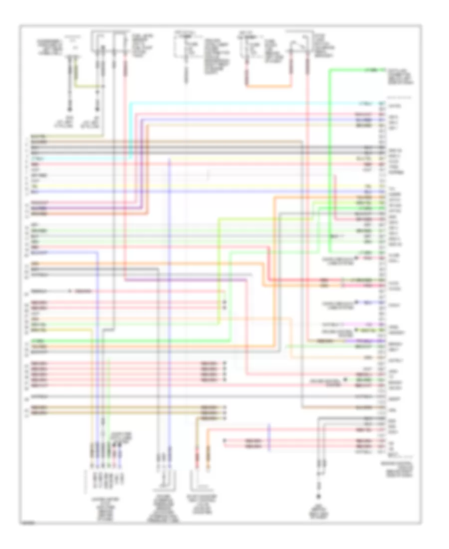
3.5L, Engine Performance Wiring Diagram (3 of 4) for Nissan Maxima SL 2008
List of elements for 3.5L, Engine Performance Wiring Diagram (3 of 4) for Nissan Maxima SL 2008:
- (left rear of engine) (a/t) front electronic controlled engine mount
- (right rear of engine) (a/t) rear electronic controlled engine mount
- (top front of engine) vias control solenoid valve
- Air fuel ratio sensor 1 (bank 1) (right front side of engine)
- Air fuel ratio sensor 1 (bank 2) (left front side of engine)
- Camshaft position sensor (phase) (bank 2) (on rear of left cyl head)
- Engine coolant temperature sensor (on left rear of engine)
- Evap control system pressure sensor (under vehicle, near evap canister)
- Fuse 10a
- Fuse 15a
- Fuse block (j/b) (behind left side of dash)
- Heated oxygen sensor 2 (bank 1) (on front of exhaust tube assembly)
- Heated oxygen sensor 2 (bank 2) (on left exhaust manifold)
- Hot at all times
- Hot in on or start
- Intake valve timing control solenoid valve (bank 1) (top front of right cyl head)
- Intake valve timing control solenoid valve (bank 2) (top front of left cyl head)
- Loop wire
- M79 (behind right end of dash)
- Mass airflow (maf) sensor (on intake air duct)
- Pnk
- Red
3.5L, Engine Performance Wiring Diagram (4 of 4) for Nissan Maxima SL 2008
List of elements for 3.5L, Engine Performance Wiring Diagram (4 of 4) for Nissan Maxima SL 2008:
- (at left "b" pillar)
- (at left "c" pillar)
- A/f-ia1
- A/f-ia2
- A/f-ip2
- Af-un2
- Aps1
- Aps2
- Ascdsw
- Avcc
- Avcc2
- B19
- Batt
- Bncsw
- Brksw
- Can l
- Can-h
- Can-l
- Cdcv
- Computer data lines system
- Condenser 1 (forward of left rear wheelwell)
- Cruise control system
- Data link connector (below left side of dash)
- Engine control module (behind right side of dash)
- Evap canister vent control valve (on evap canister)
- Fpr
- Fuel level sensor unit & fuel pump (in fuel tank)
- Fuse 10a
- Fuse 15a
- Fuse block (j/b) (behind left side of dash)
- Gnd
- Gnd a
- Gnd a2
- Hot at all times
- Ign 1
- Ign 2
- Ign 3
- Ign 4
- Ign 5
- Ign 6
- Ign sw
- Ipdm e/r (intelligent power distribution module engine room) (right front of engine compt)
- Kline
- M80 (behind right end of dash)
- Motrly
- Neut
- O2srr
- Pdpres
- Pn (ecm)
- Pnk
- Power steering pressure sensor (on power steering high pressure tube)
- Red
- Rx cmtr
- Sen gnd
- Ssoff
- Stop lamp switch (on brake pedal bracket)
- Tps2
- Tx cmtr
- Unified meter & a/c amplifier (behind center of dash)
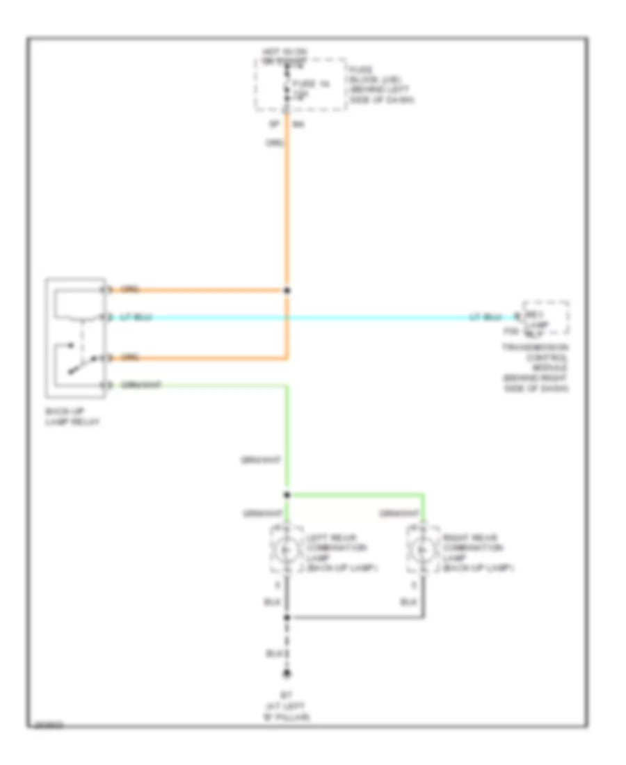
EXTERIOR LIGHTS
Back-up Lamps Wiring Diagram for Nissan Maxima SL 2008
List of elements for Back-up Lamps Wiring Diagram for Nissan Maxima SL 2008:
- (at left "b" pillar)
- Back-up lamp relay
- Fuse 14 10a
- Fuse block (j/b) (behind left side of dash)
- Hot in on or start
- Lamp f56 rly
- Left rear combination lamp (back-up lamp)
- Rev
- Right rear combination lamp (back-up lamp)
- Transmission control module (behind right side of dash)
Exterior Lamps Wiring Diagram (1 of 2) for Nissan Maxima SL 2008
List of elements for Exterior Lamps Wiring Diagram (1 of 2) for Nissan Maxima SL 2008:
- (at left side of engine compt) e15
- (below left side of dash)
- +ig
- Acc sw
- B7 (at left "b" pillar)
- Bat (f/l)
- Bat (fuse)
- Body control module (bcm) (near fuse block (j/b))
- Can-h
- Can-l
- Combi sw input 1
- Combi sw input 2
- Combi sw input 3
- Combi sw input 4
- Combi sw input 5
- Combi sw out 1
- Combi sw out 2
- Combi sw out 3
- Combi sw out 4
- Combi sw out 5
- Combination switch
- Computer data lines system
- Cornering
- Cpu
- Data link connector
- E121
- E122
- E124
- E24 (at right side of engine compt)
- Flasher out (left)
- Flasher out (right)
- Fuse & fusible link box (at left front of engine compt)
- Fuse 34 15a
- Fuse 41 15a
- Fusible link f 50a
- Gnd
- Gnd (power)
- Gnd (signal)
- Hazard sw
- Hazard switch
- Hot at all times
- Hot in on or start
- Ign sw
- Ignition relay
- Input 1
- Input 2
- Input 3
- Input 4
- Input 5
- Interior lights system
- Ipdm e/r (at right front of engine compt)
- Left corn lamp
- Left cornering lamp relay
- Left rear combination lamp
- M18
- M20
- M57 (behind right side of dash)
- M61 (behind right side of dash)
- Output 1
- Output 2
- Output 3
- Output 4
- Output 5
- Park
- Pnk
- Red
- Right corn lamp
- Right cornering lamp relay
- Right front combination lamp
- Right rear combination lamp
- Stop
- Tail
- Tail lamp relay
- Tail/ stop
- Tail/l rly
- Turn
Exterior Lamps Wiring Diagram (2 of 2) for Nissan Maxima SL 2008
List of elements for Exterior Lamps Wiring Diagram (2 of 2) for Nissan Maxima SL 2008:
- (behind right side of dash) m61
- 12p m4
- 15p
- 8q e30
- B117 (at right "b" pillar)
- B7 (at left "b" pillar)
- Bat
- Batt
- Buzzer
- Can-h
- Can-l
- Combination meter
- Cornering
- E15 (at left side of engine compt)
- Fuse 10a
- Fuse block (j/b) (behind left side of dash)
- Gnd
- Gnd (ill)
- Gnd (pwr)
- High mounted stop lamp
- Hot at all times
- Hot in acc or on
- Hot in on or start
- Ign
- Interior lights system
- Left front combination lamp
- Left license plate lamp
- Left turn ind
- M4 8p
- M49
- M50
- M57 (behind right side of dash)
- Park
- Pnk
- Right license plate lamp
- Right turn ind
- Rx (comb meter)
- Stop lamp switch (on brake pedal bracket)
- Turn
- Tx (comb meter)
- Unified meter & a/c amplifier (behind center of dash)
- Unified meter control unit
- W/ rear spoiler
- W/o rear spoiler
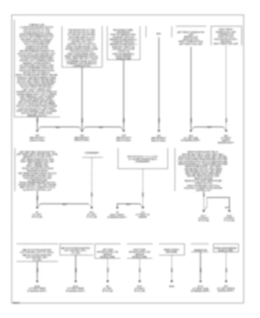
GROUND DISTRIBUTION
Ground Distribution Wiring Diagram for Nissan Maxima SL 2008
List of elements for Ground Distribution Wiring Diagram for Nissan Maxima SL 2008:
- Abs actuator & electric unit (control unit) (w/ tcs) &
- Abs actuator & electric unit (control unit), (w/ vdc)
- B107 (at right "b" pillar)
- B117 (at right "b" pillar)
- B132 (at right "c" pillar)
- B19 (at left "c" pillar)
- B352
- B5 (at left "b" pillar)
- B7 (at left "b" pillar)
- Condenser 1
- Crash zone sensor (shield wire)
- E116 (at right side of engine compt)
- E126 (at right rear of engine compt)
- E133 (at right rear of engine compt)
- E14 (at left side of engine compt)
- E15 (at left side of engine compt)
- E24 (at right side of engine compt)
- Ecm
- Ecm (shield wire), crankshaft position sensor (pos), camshaft position sensor (phase) (bank 2), camshaft position sensor (phase) (bank 1) electric throttle control actuator (throttle position sensor) & knock sensor (shield wire)
- F16 (at front of engine)
- F9 (right front of engine compt)
- Fuse box (j/b), illumination control switch, vdc off switch (w/ vdc), tcs off switch (w/ tcs), door mirror remote control switch, adp steering switch, bcm (body control module), nats antenna amplifier, data link connector, combination meter, combination switch, heated steering combination switch, shift lock control unit, air bag diagnosis sensor unit, automatic drive positioner control unit, steering angle sensor, unified meter & a/c amplifier, glove box lamp, front passenger air bag off indicator, rear sonar system off switch, a/c display, front power socket (front center console), heated steering wheel switch, left front heated seat switch, right front heated seat switch, rear sunshade front switch, front air control, left vanity mirror lamp, sunroof motor, auto anti-dazzling inside mirror, right vanity mirror lamp, personal lamp, interior room lamp (room/map lamps), left door mirror, memory seat switch, trunk & fuel lid opener switch, main power window & door lock/unlock switch, left front door lock assembly (key cylinder switch) & left front door request switch
- Generator
- Ignition coils 1, 2, 3, 4, 5 & 6 (w/ power transistor) & condenser 2
- Left front combination lamp, brake fluid level switch, front wiper motor & left front fog lamp
- Left side air bag (satellite) sensor (shield wire)
- M57 (behind right side of dash)
- M61 (behind right side of dash)
- M79 (behind right end of dash)
- M80 (behind right end of dash)
- Rear power socket relay, heated seat relay, right seat belt buckle switch, right front seat heater, right subwoofer, bose speaker amplifier, high mounted stop lamp (w/o rear spoiler), rear sunshade unit, subwoofer amplifier, rear power socket, left rear heated seat switch, right rear heated seat switch, left rear seat heater, right rear seat heater, rear console lamp, rear sunshade rear switch, right rear power window switch, right power seat switch & occupant classification system control unit
- Rear window defogger
- Right front combination lamp, washer fluid level switch, cooling fan motor 2, ipdm e/r & right front fog lamp
- Right side air bag (satellite) sensor (shield wire)
- Tcs off switch (w/ tcs), vdc off switch (w/ vdc) cvt device, fan control amplifier, display unit (w/ navigation), display control unit, navi control unit, av switch, front power socket, tcm power window & right door lock/unlock switch, right door mirror, right front door request switch, intelligent key unit, trunk lid opener cancel switch, steering lock solenoid & hazard switch
HEADLIGHTS
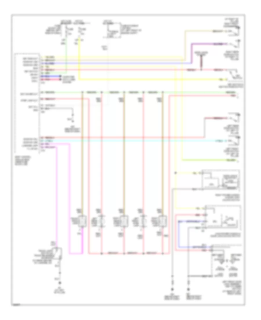
Headlights Wiring Diagram for Nissan Maxima SL 2008
List of elements for Headlights Wiring Diagram for Nissan Maxima SL 2008:
- (behind center of dash) unified meter & a/c amplifier
- (behind left side of dash)
- (behind right side of dash) m57
- (halogen) high & low
- 12p
- 15p
- Acc sw
- Auto lt in
- Auto lt pwr
- Bat (f/l)
- Body control module (bcm) (near fuse block (j/b))
- Brake ind
- Can-h
- Can-l
- Combi sw in 1
- Combi sw in 2
- Combi sw in 3
- Combi sw in 4
- Combi sw in 5
- Combi sw out 1
- Combi sw out 2
- Combi sw out 3
- Combi sw out 4
- Combi sw out 5
- Combination meter
- Combination switch
- Computer data lines system
- Cpu
- Door sw (as)
- Door sw (dr)
- Door sw (rl)
- Door sw (rr)
- E121
- E122
- E124
- E15 (at left side of engine compt)
- E24 (at right side of engine compt)
- Fr fog
- Front fog lamp relay
- Fuse & fusible link box (at left front of engine compt)
- Fuse 10a
- Fuse 15a
- Fuse 34 15a
- Fuse 43 15a
- Fuse block (j/b)
- Fusible link f 50a
- Gnd
- Gnd (sig)
- H/lp hi
- H/lp lo
- Headlamp high relay
- Headlamp low relay
- Hid cont
- High & low (xenon)
- High beam ind
- High beam solenoid
- Hot at all times
- Hot in on or acc
- Hot in on or start
- Ign sw
- Input 1
- Input 2
- Input 3
- Input 4
- Input 5
- Intelligent power distribution module engine room (ipdm e/r) (at right front of engine compt)
- Left front combination lamp (headlamp)
- Left front door switch (at left "b" pillar)
- Left front fog lamp
- Left rear door switch (at left "c" pillar)
- M18
- M19
- M20
- M49
- M57 (behind right side of dash)
- Optical sensor (at top left of dash)
- Output
- Output 1
- Output 2
- Output 3
- Output 4
- Output 5
- Parking brake switch (w/ drl) (at base of parking brake lever assembly)
- Pnk
- Pwr
- Red
- Right front combination lamp (headlamp)
- Right front door switch (at right "b" pillar)
- Right front fog lamp
- Right rear door switch (at right "c" pillar)
- Rx (comb meter)
- Sens gnd
- Tx (comb meter)
- Unified meter control unit
- Warning system
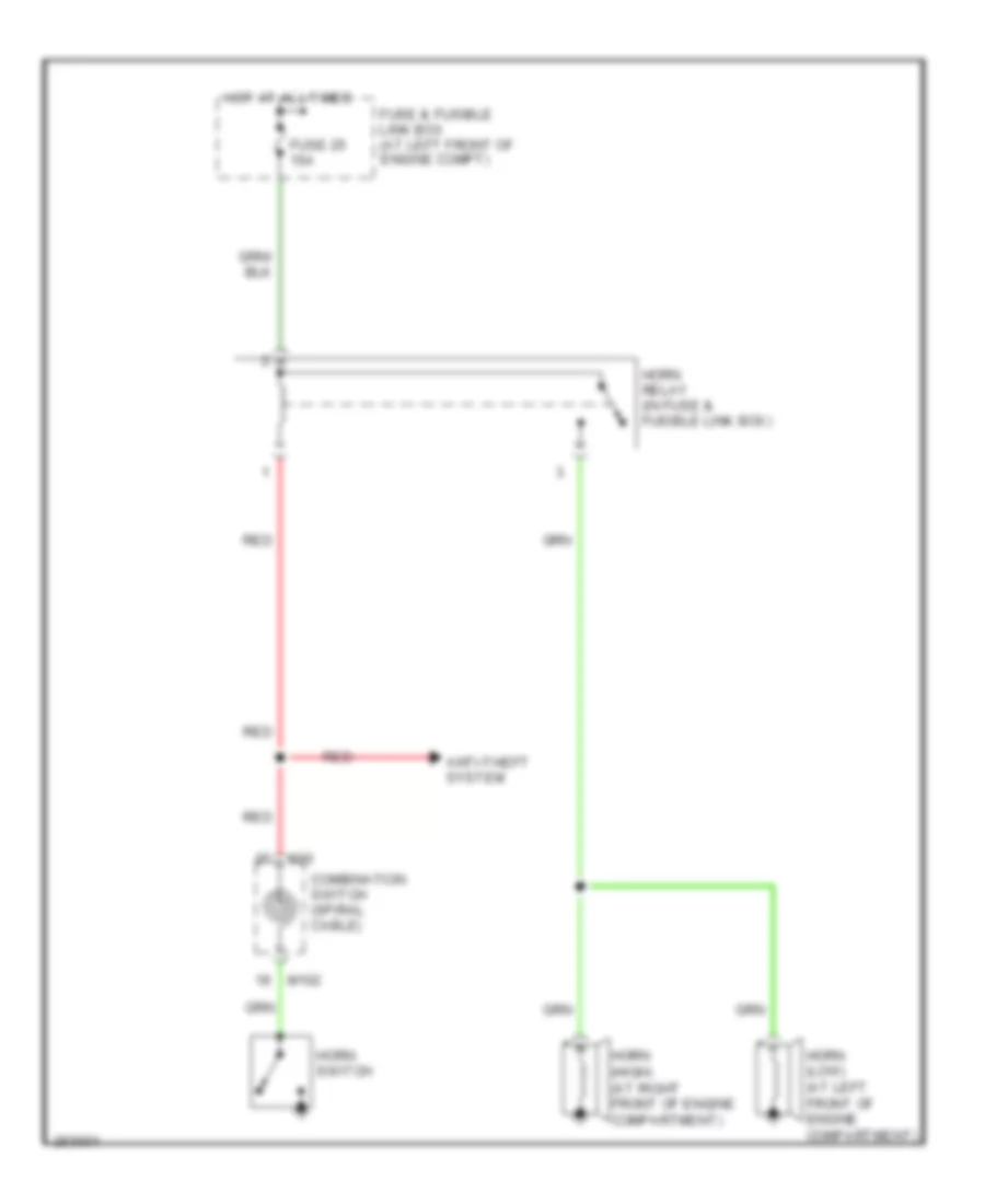
HORN
Horn Wiring Diagram for Nissan Maxima SL 2008
List of elements for Horn Wiring Diagram for Nissan Maxima SL 2008:
- Anti-theft system
- Combination switch (spiral cable)
- Fuse & fusible link box (at left front of engine compt)
- Fuse 25 15a
- Horn (high) (at right front of engine compartment)
- Horn (low) (at left front of engine compartment)
- Horn relay (in fuse & fusible link box)
- Horn switch
- Hot at all times
- M102
- M30
- Red
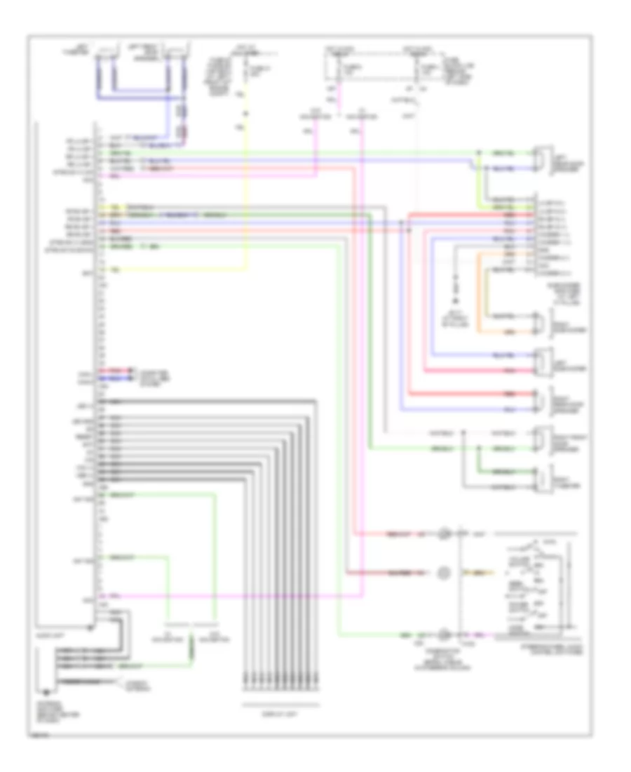
INSTRUMENT CLUSTER
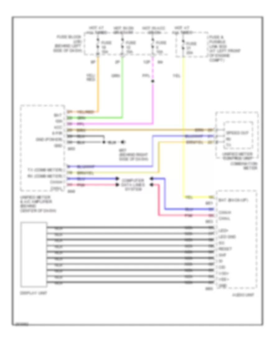
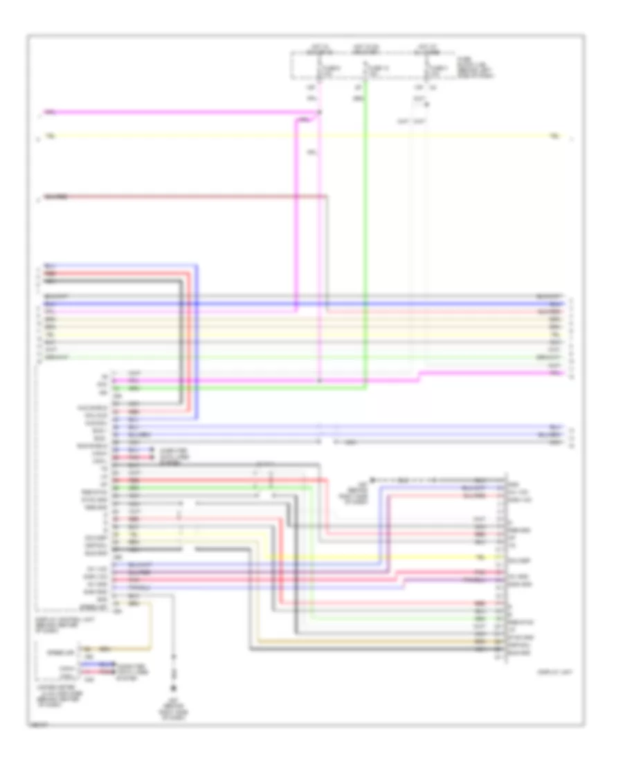
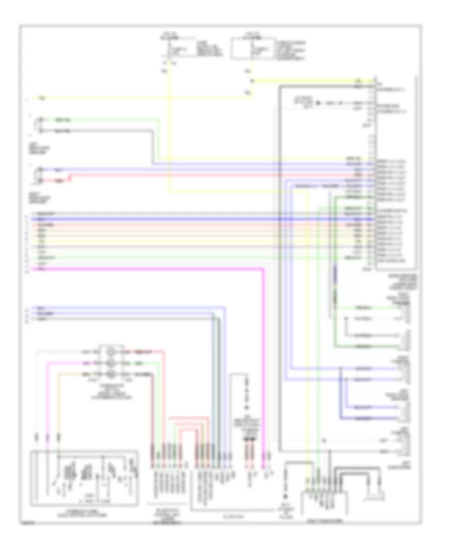
Display Wiring Diagram for Nissan Maxima SL 2008
List of elements for Display Wiring Diagram for Nissan Maxima SL 2008:
- 12p
- 8 p/r
- Acc
- Audio unit
- Bat
- Bat (back-up)
- C/d
- Can-h
- Can-l
- Combination meter
- Computer data lines system
- Display unit
- Fuse & fusible link box (at left front of engine compt)
- Fuse 10a
- Fuse 20a
- Fuse block (j/b) (behind left side of dash)
- Gnd
- Gnd (power)
- Hot at all times
- Hot in acc or on
- Hot in on or start
- Ign
- Led gnd
- Led+
- M49
- M50
- M51
- M53
- M57 (behind right side of dash)
- M60
- Nca
- Pnk
- Reset
- Rx (comb meter)
- Sht
- Speed out
- Tx (comb meter)
- Unified meter & a/c amplifier (behind center of dash)
- Unified meter control unit
- Vee+
- Voo+
Gauges & Indicators Wiring Diagram for Nissan Maxima SL 2008
List of elements for Gauges & Indicators Wiring Diagram for Nissan Maxima SL 2008:
- (at left side of engine compt) e15
- (behind right side of dash) m57
- (w/ odo/trip meter & cvt indicator) unified meter control unit
- 12p m4
- 3n m3
- 8p/r
- Abs actuator & electric unit (control unit) (at right rear corner of engine compt)
- Abs ind
- Acc
- Air bag ind
- Auto anti- dazzling inside mirror (compass)
- Batt
- Belt ind
- Body control module (bcm) (near fuse block (j/b))
- Br fl sw
- Brake fluid level switch (on master cylinder reservoir)
- Brake ind
- Buzzer
- Can-h
- Can-l
- Charge ind
- Combination meter
- Computer data lines system
- Cpu
- Cruise ind
- Cvt ind
- Door ind
- Door sw (as)
- Door sw (dr)
- Door sw (rl)
- Door sw (rr)
- E121
- Fuel gauge
- Fuel ind
- Fuel level sensor unit & fuel pump (fuel level sensor) (in fuel tank)
- Fuel sens
- Fuel sens gnd
- Fuse 10a
- Fuse 15a
- Fuse block (j/b) (behind left side of dash)
- Gnd
- Gnd (power)
- High beam ind
- Hot at all times
- Hot in acc or on
- Hot in on
- Hot in on or start
- Ign
- Ign-2
- Intelligent power distribution module engine room (ipdm e/r) (at right front of engine compt)
- Interior lights system
- Key (green) ind
- Key (red) ind
- Left front door switch (at left "b" pillar)
- Left rear door switch (at left "c" pillar)
- Left turn ind
- M18
- M19
- M4 2p
- M49
- M50
- M61 (behind right side of dash)
- M89
- Malfunction ind lamp
- Meter illum
- Odo/trip meter illum
- Oil ind
- Oil pressure sw
- Oil pressure switch (on right front side of oil pan)
- P-shift ind
- Parking brake switch (at base of parking brake lever assembly)
- Pnk
- Right front door switch (at right "b" pillar)
- Right rear door switch (at right "c" pillar)
- Right turn ind
- Set ind
- Slip ind
- Speedometer
- Starting/charging system
- Tachometer
- Tcs off ind (w/o vdc)
- Tire pressure ind
- Trunk ind
- Trunk lamp switch & trunk release solenoid (at center rear of luggage compt lid)
- Trunk sw
- Unified meter & a/c amplifier (behind center of dash)
- Vdc off ind (w/ vdc)
- W/ vdc
- Warning system
- Washer ind
- Water temp gauge
- Wiper/washer system
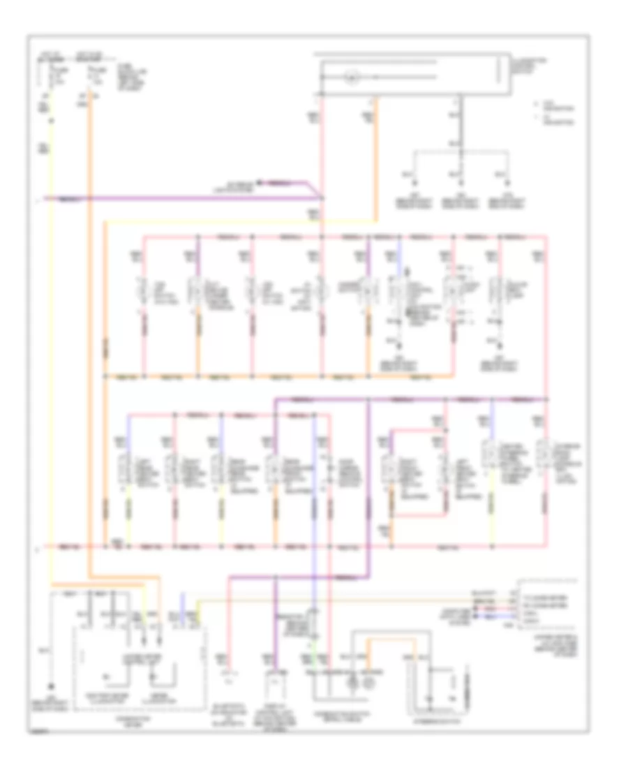
INTERIOR LIGHTS
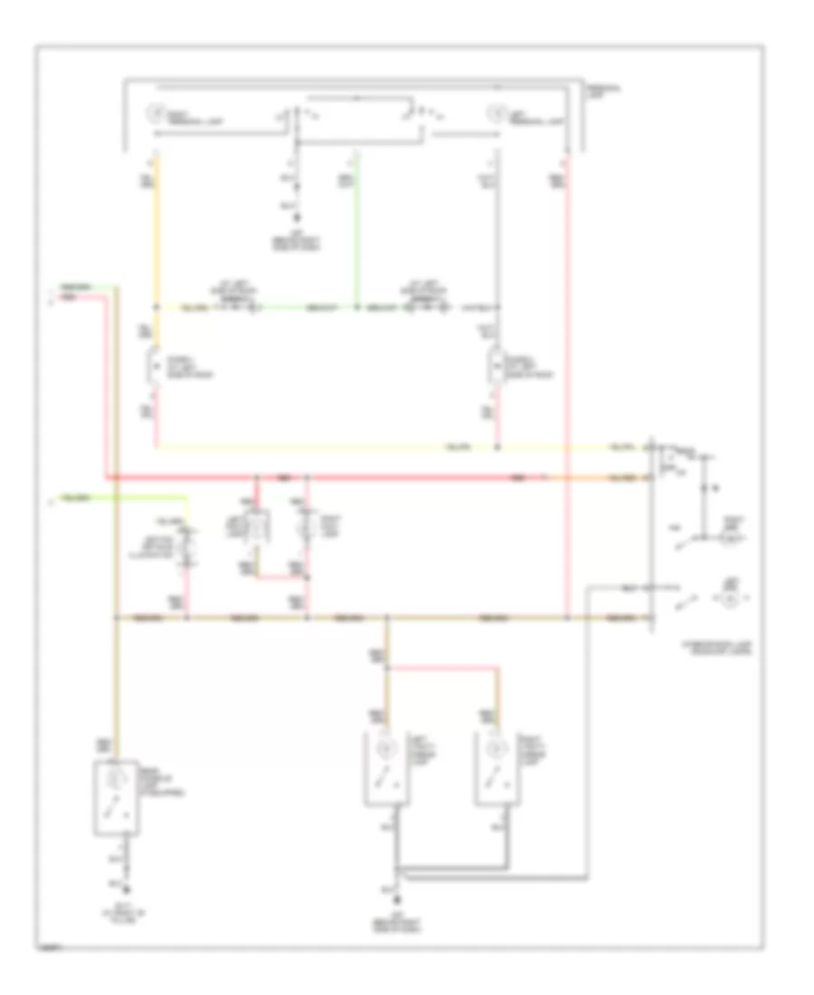
Courtesy Lamps Wiring Diagram (1 of 2) for Nissan Maxima SL 2008
List of elements for Courtesy Lamps Wiring Diagram (1 of 2) for Nissan Maxima SL 2008:
- (at right "b" pillar) right front door switch
- 15p
- B7 (at left "b" pillar)
- Bat (f/l)
- Bat saver out
- Between full stroke & n
- Body control module (bcm) (near fuse block (j/b))
- Bus
- Can-h
- Can-l
- Computer data lines
- Cpu
- Door lock & unlock sw
- Door locks system
- Door sw (as)
- Door sw (dr)
- Door sw (rl)
- Door sw (rr)
- Full stroke
- Fuse & fusible link box (at left front of engine compt)
- Fuse 10a
- Fuse block (j/b) (behind left side of dash)
- Fusible link f 50a
- Gnd
- Hot at all times
- Hot in on or start
- Ign sw
- Key ring out
- Key switch
- Key switch & ignition knob switch
- Left front door lock assembly (key cylinder switch) (at rear of left front door)
- Left front door switch (at left "b" pillar)
- Left front step lamp
- Left rear door switch (at left "c" pillar)
- Left rear step lamp
- Lock
- Lock switch
- Luggage lamp
- M18
- M19
- M20
- M4 14p
- M57 (behind right side of dash)
- M61 (behind right side of dash)
- Main power window & door lock/unlock switch
- Pnk
- Red
- Right front step lamp
- Right power window & door lock/ unlock switch
- Right rear door switch (at right "c" pillar)
- Right rear step lamp
- Step lamp out
- System
- T/l op sw
- Trunk lamp switch & trunk release solenoid (at rear center of luggage lid)
- Trunk room lamp
- Unlock
- Unlock switch
Courtesy Lamps Wiring Diagram (2 of 2) for Nissan Maxima SL 2008
List of elements for Courtesy Lamps Wiring Diagram (2 of 2) for Nissan Maxima SL 2008:
- (at left side of roof) diode 1
- (at left side of roof) diode 3
- B117 (at right "b" pillar)
- Diode 2 (at left side of roof)
- Diode 4 (at left side of roof)
- Door
- Ignition keyhole illumination
- Interior room lamp (room/map lamps)
- Left foot lamp
- Left map
- Left personal lamp
- Left vanity mirror lamp
- M57 (behind right side of dash)
- Off on
- Personal lamp
- Rear console lamp (if equipped)
- Red
- Right foot lamp
- Right map
- Right personal lamp
- Right vanity mirror lamp
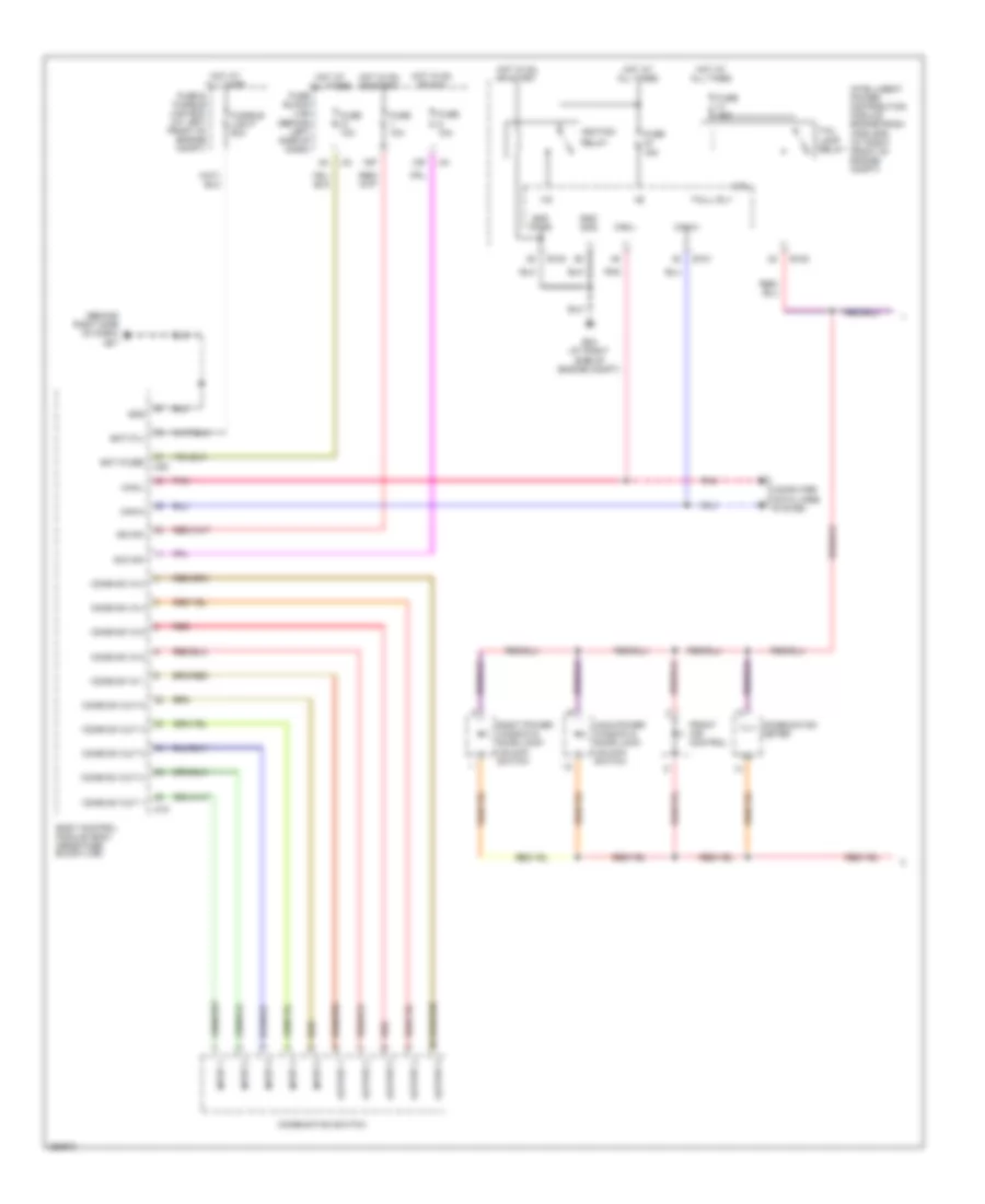
Instrument Illumination Wiring Diagram (1 of 2) for Nissan Maxima SL 2008
List of elements for Instrument Illumination Wiring Diagram (1 of 2) for Nissan Maxima SL 2008:
- (behind left side of dash)
- (behind right side of dash) m57
- +ig
- 12p
- 15p
- Acc sw
- Bat (f/l)
- Bat (fuse)
- Body control module (bcm) (near fuse block (j/b))
- Can-h
- Can-l
- Comb sw in 1
- Comb sw in 2
- Comb sw in 3
- Comb sw in 4
- Comb sw in 5
- Comb sw out 1
- Comb sw out 2
- Comb sw out 3
- Comb sw out 4
- Comb sw out 5
- Combination meter
- Combination switch
- Computer data lines system
- Cpu
- E121
- E122
- E124
- E24 (at right side of engine compt)
- Front air control
- Fuse & fusible link box (at left front of engine compt)
- Fuse 10a
- Fuse 15a
- Fuse block (j/b)
- Fusible link f 50a
- Gnd
- Gnd (pwr)
- Gnd (sig)
- Hot at all times
- Hot in on or acc
- Hot in on or start
- Ign sw
- Ignition
- Ill+
- Ill-
- Input 1
- Input 2
- Input 3
- Input 4
- Input 5
- Intelligent power distribution module engine room (ipdm e/r) (at right front of engine compt)
- M18
- M20
- Main power window & door lock/ unlock switch
- Output 1
- Output 2
- Output 3
- Output 4
- Output 5
- Pnk
- Red
- Relay
- Right power window & door lock/ unlock switch
- Tail lamp relay
- Tail/l rly
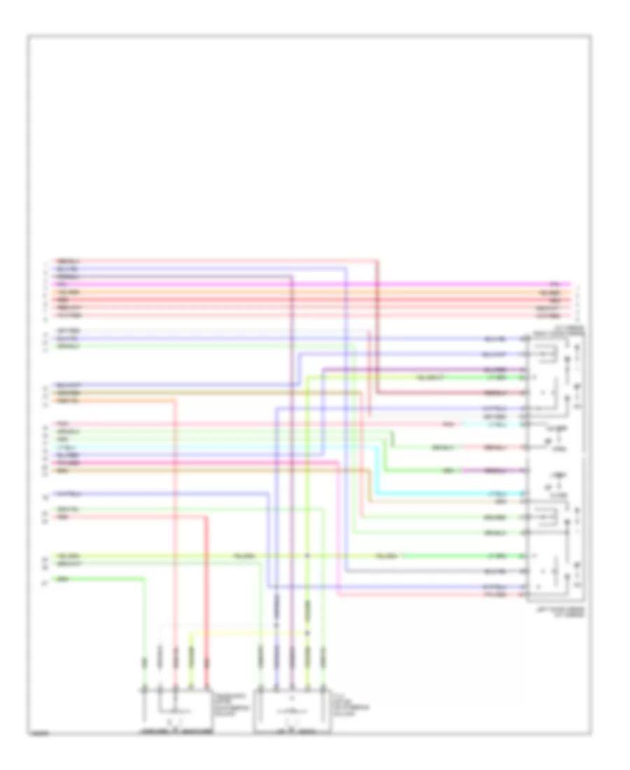
Instrument Illumination Wiring Diagram (2 of 2) for Nissan Maxima SL 2008
List of elements for Instrument Illumination Wiring Diagram (2 of 2) for Nissan Maxima SL 2008:
- Audio unit
- Av switch (w/ navi- gation)
- Can-h
- Can-l
- Combination meter
- Combination switch (spiral cable)
- Computer data lines system
- Cvt device (under center console)
- Display control unit (w/ navigation) (behind center of dash)
- Door mirror remote control switch
- Exterior lights system
- Fuse 10a
- Fuse block (j/b) (behind left side of dash)
- Glove box lamp
- Hazard switch
- Heated steering wheel switch (w/ heated steering wheel)
- Hot at all times
- Hot in on or start
- Ill
- Illumination
- Illumination control switch
- Interior room lamp (console box illumi- nation)
- Left front heated seat switch (if equipped)
- Left rear heated seat switch
- M102
- M30
- M43
- M49
- M51
- M57 (behind right side of dash)
- M61 (behind right side of dash)
- M79 (behind right end of dash)
- M94
- M97
- Meter illumination
- Navi control unit (w/ navigation) m96 (behind center of dash)
- Odo/trip meter illumination
- Pnk
- Rear sunshade front switch (if equipped)
- Rear sunshade rear switch (if equipped)
- Resistor 1 (behind center of dash)
- Right front heated seat switch (if equipped)
- Right rear heated seat switch
- Rx (comb meter)
- Steering switch
- Tcs off switch (w/o vdc)
- Tx (comb meter)
- Unified meter & a/c amplifier (behind center of dash)
- Unified meter control unit
- Vdc off switch (w/ vdc)
- W/ navigation
- W/o navigation
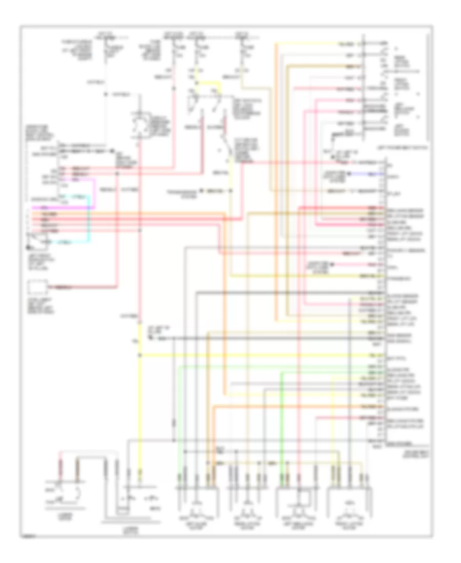
MEMORY SYSTEMS
Memory Systems Wiring Diagram (1 of 3) for Nissan Maxima SL 2008
List of elements for Memory Systems Wiring Diagram (1 of 3) for Nissan Maxima SL 2008:
- (behind right side of dash) m61
- 12p m4
- 13p
- Address-1
- Address-2
- Adp steering switch (behind left side of dash)
- Automatic drive positioner control unit (behind right center of dash)
- Backward
- Bat (fuse)
- Bat (ptc)
- Change over switch
- Close
- Door mirror remote control switch
- Down
- Forward
- Fuse 10a
- Fuse block (j/b) (behind left side of dash)
- Gnd
- Hot at all times
- Hot in acc or on
- Ind-1
- Ind-2
- Interior lights system
- Left
- Lh mtr horiz
- Lh mtr vert
- Lh select
- Lh sens horiz
- Lh sens vert
- M41
- M42
- M57 (behind right side of dash)
- Mirror switch
- Mtr common
- Off
- Open
- Pnk
- Pwr
- Red
- Retractor switch
- Rh mtr horiz
- Rh mtr vert
- Rh select
- Rh sens horiz
- Rh sens vert
- Right
- Seat memory switch
- Set
- Tele backward
- Tele forward
- Tele sens
- Telescopic switch
- Tilt down
- Tilt sens
- Tilt switch
- Tilt up
Memory Systems Wiring Diagram (2 of 3) for Nissan Maxima SL 2008
List of elements for Memory Systems Wiring Diagram (2 of 3) for Nissan Maxima SL 2008:
- (at mirror) right door mirror
- Backward
- Close
- Down
- Forward
- Left door mirror (at mirror)
- Open
- Pnk
- Red
- Telescopic motor (on steering column)
- Tilt motor (on steering column)
Memory Systems Wiring Diagram (3 of 3) for Nissan Maxima SL 2008
List of elements for Memory Systems Wiring Diagram (3 of 3) for Nissan Maxima SL 2008:
- (at left "b" pillar) b7
- (near fuse block (j/b)) body control module (bcm)
- 15p
- 2n m3
- Acc sw
- B401
- B402
- Backward
- Bat (f/l)
- Bat (fuse)
- Bat (ptc)
- Bwd
- Can-h
- Can-l
- Circuit breaker (behind left side of dash)
- Computer data lines system
- Cvt device (detention switch key) (under center console)
- Door sw (dr)
- Driver seat control unit
- Forward
- Fr lift (down)
- Fr lift sensor
- Fr lifting mtr (up)
- Front lift (down)
- Front lift (up)
- Front lifting motor
- Front lifting switch
- Fuse & fusible link box (at left front of engine compt)
- Fuse 10a
- Fuse block (j/b) (behind left side of dash)
- Fusible link f 50a
- Fwd
- Gnd (power)
- Gnd (signal)
- Gnd sensor
- Hot at all times
- Hot in on or start
- Hot in start
- Ign
- Intelligent key unit (behind left side of dash)
- Key sw
- Key switch & key lock solenoid (on steering column)
- Left front door switch (at left "b" pillar)
- Left power seat switch
- Left reclining motor
- Left reclining switch
- Left slide motor
- Left sliding switch
- Lumbar motor
- Lumbar switch
- M18
- M19
- M20
- M4 14p
- M57 (behind right side of dash)
- P range sw
- Pnk
- Pwr sply (sensor)
- Rear lift (down)
- Rear lift (up)
- Rear lifting (up)
- Rear lifting motor
- Rear lifting switch
- Recline (fr)
- Recline (rr)
- Reclining (fr)
- Reclining mtr (rr)
- Reclining sensor
- Red
- Rr lifting sensor
- Slide (fr)
- Slide (rr)
- Sliding (fr)
- Sliding mtr (rr)
- Sliding sensor
- St_sw
- Transmissions system
NAVIGATION
Navigation Wiring Diagram (1 of 2) for Nissan Maxima SL 2008
List of elements for Navigation Wiring Diagram (1 of 2) for Nissan Maxima SL 2008:
- (behind center of dash) navi control unit
- (behind right end of dash) m79
- 12p
- 13p
- 8p/r
- Acc
- Ant gnd (gps)
- Ant sig (gps)
- Back up light relay (left side of engine compartment)
- Bat
- Body computer system
- Bus +
- Bus -
- Can-h
- Can-l
- Computer data lines system
- Exterior lights system
- F56
- Fuse & fusible link box (at left front of engine compt)
- Fuse 10a
- Fuse 20a
- Fuse block (j/b) (behind left side of dash)
- Gnd
- Gnd (pwr)
- Gps antenna (under top center of dash)
- Hot at all times
- Hot in acc or on
- Hot in on or start
- Ign
- Ill
- Interior lights system
- M121
- M49
- M50
- M61 (behind right side of dash)
- M96
- M97
- Nca
- Pnk
- Rev lamp rly
- Rgb shield
- Rgb sync
- Shield
- Speed (8)
- Sync shield
- Transmission control module (tcm) (behind right side of dash)
- Unified meter & a/c amplifier (behind center of dash)
- Voice (+)
- Voice (-)
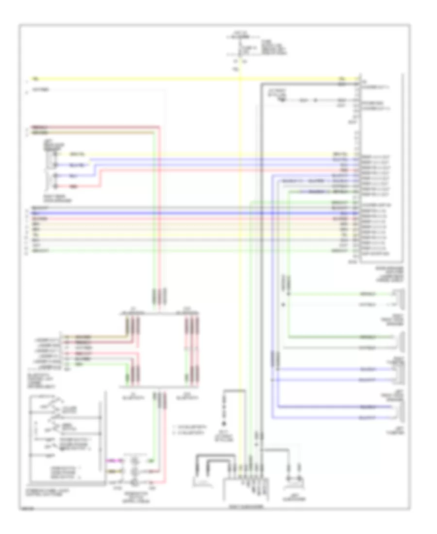
Navigation Wiring Diagram (2 of 2) for Nissan Maxima SL 2008
List of elements for Navigation Wiring Diagram (2 of 2) for Nissan Maxima SL 2008:
- Acc
- Audio shield
- Audio unit
- Audio-dcu
- Av switch
- B41
- Bat
- Bus (+)
- Bus (-)
- Bus gnd
- Bus shield
- Can-h
- Can-l
- Combination switch (spiral cable)
- Computer data lines system
- Dcu-audio
- Dcu-dsp
- Display control unit (behind center of dash)
- Display unit
- Down
- Dsp shield
- Dsp-dcu
- Frsp lh (+)
- Frsp lh (-)
- Gnd
- Ign
- Ill
- Ill cont
- In 2 ladder
- In gnd ladder
- Interior lights system
- Inv gnd
- Inv vcc
- Ladder gnd
- Ladder in 1
- M102
- M30
- M43
- M45
- M61 (behind right side of dash)
- M94
- M95
- Mode switch
- Nca
- Off
- Out 1 audio
- Out 2 audio
- Pnk
- Power switch
- Red
- Rgb gnd
- Rgb sync
- Seek switch
- Shield
- Sig gnd
- Sig vcc
- Sign gnd
- Sign vcc
- Sound systems
- Speed (8p)
- Steering wheel audio control switches
- Sw a strg
- Sw b strg
- Sw c strg
- Sync gnd
- Voice (+)
- Voice (-)
- Volume switch
Rear Sonar Wiring Diagram for Nissan Maxima SL 2008
List of elements for Rear Sonar Wiring Diagram for Nissan Maxima SL 2008:
- (behind right side of dash) m61
- Auto
- Auto mode sw
- B7 (at left "b" pillar)
- Back-up lamp relay (left side of engine compt)
- Buzz +
- Buzz -
- Can-h
- Can-l
- Computer data lines system
- Cvt device (manual mode switch) (under center console)
- Down
- Enable disable sw
- Exterior lights system
- Fuse 10a
- Fuse block (j/b) (behind left side of dash)
- Gnd
- Hot in on or start
- Left inner rear sonar sensor (behind left center of rear bumper)
- Left outer rear sonar sensor (behind left end of rear bumper)
- Lh rr inner sig
- Lh rr outer sig
- M49
- M61 (behind right side of dash)
- Manual
- Manual mode sw
- Mode select switch
- Off ind
- Off switch
- Pnk
- Position select switch
- Pwr
- Rear sonar sensor off switch
- Red
- Rev lamp relay
- Rev lmp sig
- Rh rr inner sig
- Rh rr outer sig
- Right inner rear sonar sensor (behind right center of rear bumper)
- Right outer rear sonar sensor (behind right end of rear bumper)
- Rr sens gnd
- Rr sens pwr
- Shift down sw
- Shift up sw
- Side of dash)
- Sonar buzzer (at left kick panel)
- Sonar control unit (left side of trunk)
- Status led
- Transmission control module (tcm) (behind right f56
- Unified meter & a/c amplifier (behind center of dash)
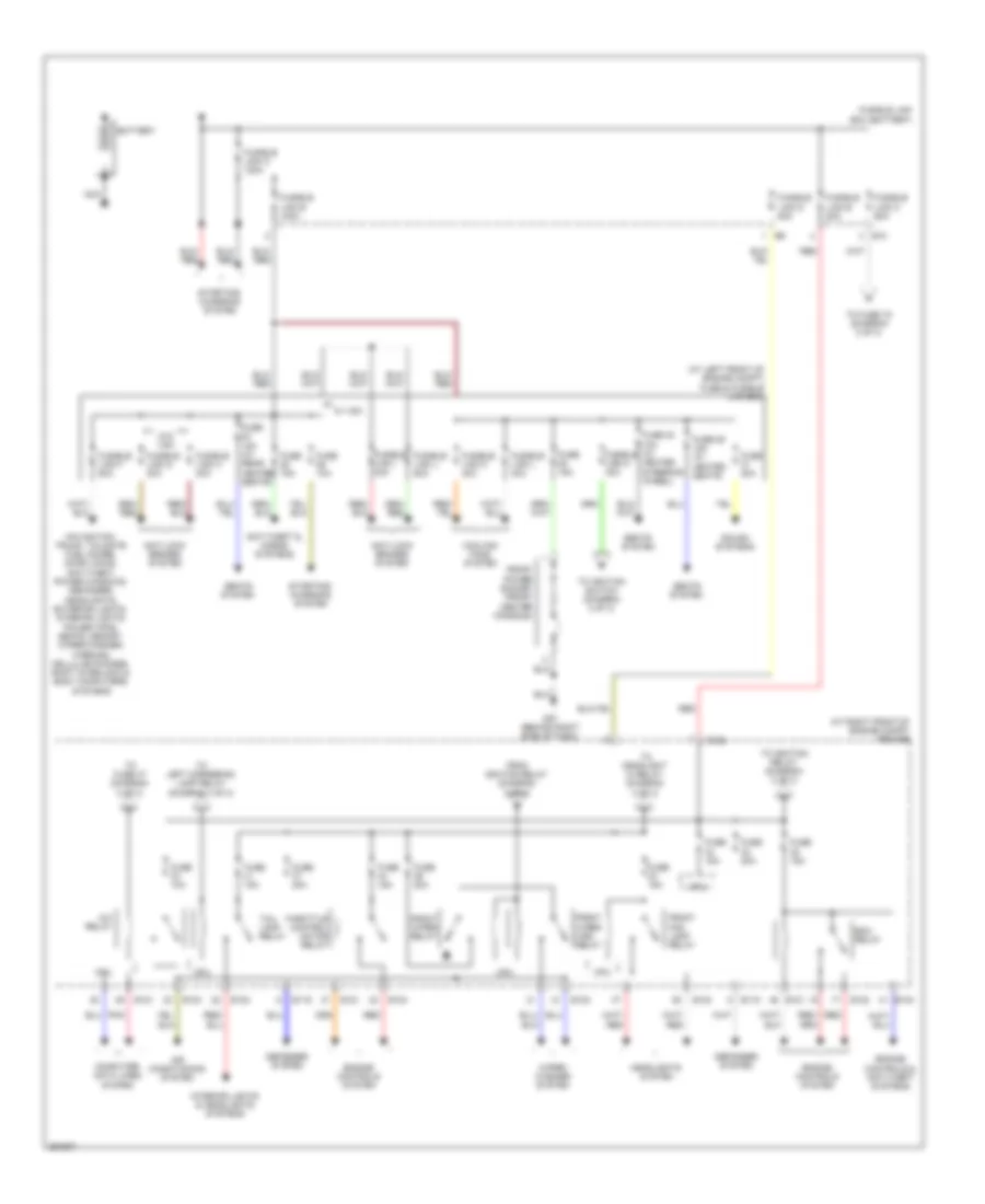
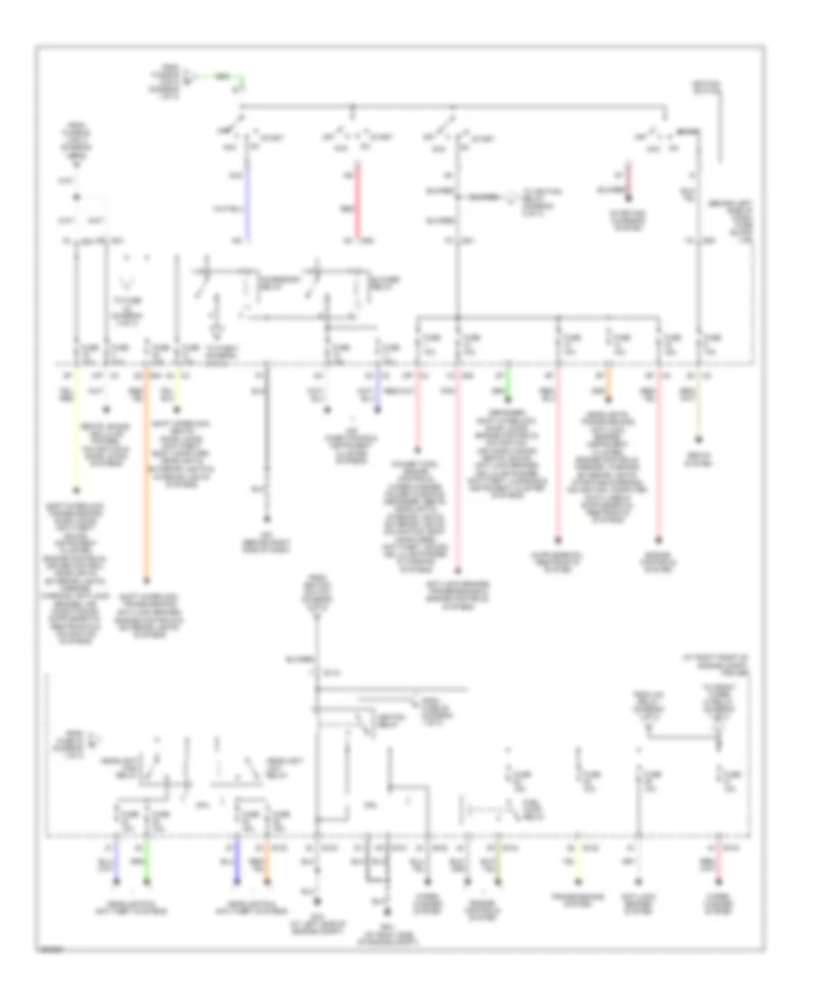
POWER DISTRIBUTION
Power Distribution Wiring Diagram (1 of 3) for Nissan Maxima SL 2008
List of elements for Power Distribution Wiring Diagram (1 of 3) for Nissan Maxima SL 2008:
- (at left front of engine compt) fuse & fusible link box
- (at right front of engine compt) ipdm e/r
- A/c relay
- Air conditioning system
- Anti-lock brakes system
- Anti-theft & horns systems
- Battery
- Computer data lines system
- Cooling fans system
- Cpu
- Defogger system
- E10
- E119
- E120
- E121
- E122
- E124
- Ecm relay
- Engine controls & anti-theft systems
- Engine controls system
- From ignition relay (diagram 2 of 3)
- Front fog lamp relay
- Front power socket (front center console)
- Front wiper high relay
- Front wiper relay
- Fuse 10a
- Fuse 15a
- Fuse 15a (w/ rear heated seats)
- Fuse 20a
- Fuse 29 15a (w/ heated seats)
- Fuse 30 10a (w/ heated steering wheel)
- Fusible link a 120a
- Fusible link b 80a
- Fusible link box (battery)
- Fusible link c 60a
- Fusible link d 80a
- Fusible link e 100a
- Fusible link f 50a
- Fusible link g 30a
- Fusible link h 30a
- Fusible link i 40a
- Fusible link j 50a
- Fusible link k 40a
- Fusible link l 40a
- Fusible link m 40a
- Headlights system
- Interior lights & headlights systems
- M57 (behind right side of dash)
- Navigation, trunk, tailgate fuel doors, door locks, anti-theft, power windows, defogger, headlights, exterior lights, interior lights, power tops, seats, memory, wiper/washer, warning, cellular phones, shift interlock & body computers systems
- Nca
- Pnk
- Red
- Seats system
- Sound systems
- Starting/ charging system
- Tail lamp relay
- Throttle control motor relay
- To fuse 19 (diagram 2 of 3)
- To fuse 47 (diagram 2 of 3)
- To headlight hi relay (diagram 2 of 3)
- To ignition relay (diagram 2 of 3)
- To ignition switch (diagram 2 of 3)
- To left cornering lamp relay (diagram 3 of 3)
- W/ vdc
- W/o vdc
- Wiper/ washer system
Power Distribution Wiring Diagram (2 of 3) for Nissan Maxima SL 2008
List of elements for Power Distribution Wiring Diagram (2 of 3) for Nissan Maxima SL 2008:
- (at right front of engine compt) ipdm e/r
- (behind left side of dash) fuse block (j/b)
- (diagram 1 of 3)
- 13p
- 15p m4
- 4n m3
- 8q e30
- Acc
- Accessory relay
- Air conditioning & instrument cluster systems
- Anti-lock brakes system
- Anti-lock brakes, transmissions & engine controls systems
- Blower relay
- Cpu
- Defogger, shift interlock, door locks, engine controls, navigation, air conditioning, seats, sound, anti-lock brakes, cellular phones, anti-theft, warning & instrument cluster systems
- E118
- E121
- E122
- E124
- E15 (at left side of engine compt)
- E24 (at right side of engine compt)
- E30
- E31
- E32
- Engine controls system
- From a/c relay (diagram 1 of 3)
- From fuse 35 (diagram 1 of 3)
- From fuse 43 (diagram 1 of 3)
- From fusible link c (diagram 1 of 3)
- From fusible link m b
- From ignition switch (diagram 2 of 3)
- Fuel pump relay
- Fuse 10a
- Fuse 15a
- Headlight high relay
- Headlight low relay
- Headlights & anti-theft systems
- Ig1
- Ig2
- Ignition relay
- Ignition switch
- M57 (behind right side of dash)
- Off
- Pnk
- Power tops, engine controls, wiper/washer, power windows, defogger, seats, headlights, interior lights, exterior lights, navigation, body computers, anti-theft, sound, cellular phones & warning systems
- Red
- Seats system
- Seats, sound, cellular phones, navigation & door locks systems
- Shift interlock, seats, door locks, anti-theft, body computer, headlights, exterior lights & interior lights systems
- Shift interlock, transmissions, anti-lock brakes, engine controls & exterior lights systems
- Start
- Starting/ charging system
- To front wiper hi relay (diagram 1 of 3)
- To fuse (diagram 3 of 3)
- To fuse 7 (diagram 3 of 3)
- To ignition relay (diagram 2 of 3)
- Transmissions system
- Wiper/ washer system
Power Distribution Wiring Diagram (3 of 3) for Nissan Maxima SL 2008
List of elements for Power Distribution Wiring Diagram (3 of 3) for Nissan Maxima SL 2008:
- (behind left side of dash) fuse block (j/b)
- 11p
- 12p
- 16p
- B117 (at right "b" pillar)
- B132 (at right "c" pillar)
- Cpu
- E122
- E124
- Exterior lights system
- From accessory relay (diagram 2 of 3)
- From fuse 41 (diagram 1 of 3)
- Front power socket
- Fuse 10a
- Fuse 15a
- Ipdm e/r (at right front of engine compt)
- Left cornering lamp relay
- M61 (behind right side of dash)
- M79 (behind right end of dash)
- Pnk
- Power antenna, door locks, anti-theft, air conditioning, mirrors, power windows, headlights, exterior lights, interior lights, cellular phones, instrument cluster, sound, navigation & seats systems
- Rear power socket
- Rear power socket relay (w/ rear console) (at right kick panel)
- Right cornering lamp relay
- Sound & power windows systems
- Sound systems
- Trunk, tailgate, fuel doors system
POWER DOOR LOCKS
Power Door Locks Wiring Diagram for Nissan Maxima SL 2008
List of elements for Power Door Locks Wiring Diagram for Nissan Maxima SL 2008:
- 13p m4
- 14p
- 4n m3
- As unlock out
- Bat (f/l)
- Bat (fuse)
- Between full stroke & n
- Body control module (bcm) (near fuse block (j/b))
- Bus
- Can-h
- Can-l
- Computer data lines system
- Cpu
- Door lock output (all)
- Door sw (as)
- Door sw (dr)
- Door sw (rl)
- Door sw (rr)
- Door unlock output (dr)
- Door unlock output (other)
- Full stroke lock switch
- Fuse & fusible link box (at left front of engine compt)
- Fuse 10a
- Fuse block (j/b) (behind left side of dash)
- Fusible link f 50a
- Gnd
- Gnd (power)
- Hot at all times
- Ignition knob switch
- Intelligent key unit (behind left side of dash)
- Key cyl lock sw
- Key cyl unlock sw
- Key sw
- Key switch
- Key switch & ignition knob switch
- Left front door lock assembly (key cylinder switch) (at rear of left front door)
- Left front door switch (at left "b" pillar)
- Left rear door lock actuator (at rear of left rear door)
- Left rear door switch (at left "c" pillar)
- Lock
- M18
- M19
- M20
- M57 (behind right side of dash)
- M61 (behind right side of dash)
- Main power window & door lock/ unlock switch
- Passenger select unlock relay (at left kick panel)
- Pnk
- Power window serial link
- Push sw
- Red
- Right front door lock actuator (at rear of right front door)
- Right front door switch (at right "b" pillar)
- Right power window & door lock/ unlock switch
- Right rear door lock actuator (at rear of right rear door)
- Right rear door switch (at right "c" pillar)
- Unlock
- Unlock switch full stroke
Power Door Locks Wiring Diagram, with Intelligent Key Unit (1 of 3) for Nissan Maxima SL 2008
List of elements for Power Door Locks Wiring Diagram, with Intelligent Key Unit (1 of 3) for Nissan Maxima SL 2008:
- (behind center of dash) unified meter & a/c amp
- (behind right end of dash) m79
- 5v ref
- Acc
- Ant+
- Ant-
- As ant (+)
- As ant (-)
- As request sw
- As unlock out
- B19 (at left "c" pillar)
- Back ant (+)
- Back ant (-)
- Bat
- Batt
- Can-h
- Can-l
- Cvt device (detention switch key) (under center console)
- Dr door ant (+)
- Dr door ant (-)
- Dr request sw
- Dr state sw
- E30
- Front console antenna (behind center of dash)
- Fuse 10a
- Fuse block (j/b) (behind left side of dash)
- Gnd
- Gnd (pwr)
- Hot at all times
- Hot in on or start
- Ign
- Ign sw
- Ignition knob switch
- Instrument panel antenna (behind center of dash)
- Intelligent key unit (behind left side of dash)
- Intelligent key warning buzzer (right front corner of engine compt)
- Key sw
- Key switch
- Key switch & ignition knob switch
- Left front door request switch
- Left front outside antenna
- M4 14p
- M49
- M50
- M57 (behind right side of dash)
- M61 (behind right side of dash)
- Outside buzzer
- P range sw
- Pnk
- Push sw
- Rear bumper antenna (behind center of rear bumper)
- Rear parcel shelf antenna (under center of rear parcel shelf)
- Red
- Remote keyless entry receiver (behind right end of dash)
- Rf tuner 5v
- Rf tuner gnd
- Rf tuner rssi
- Rf tuner sig
- Right front door request switch
- Right front outside antenna
- Room ant 1 (+)
- Room ant 1 (-)
- Room ant 3 (+)
- Room ant 3 (-)
- Room ant 4 (+)
- Room ant 4 (-)
- Shift interlock system
- Signal
- Steering lock solenoid (on steering column)
- Stop lamp sw
- Stop lamp switch (on brake pedal bracket)
- Strg c/u 5v
- Strg c/u sig
- Tr cancel sw
- Trunk opener request switch
- Trunk req sw
- Trunk, tailgate, fuel doors system
Power Door Locks Wiring Diagram, with Intelligent Key Unit (2 of 3) for Nissan Maxima SL 2008
List of elements for Power Door Locks Wiring Diagram, with Intelligent Key Unit (2 of 3) for Nissan Maxima SL 2008:
- & n
- (at rear of
- Actuator
- Bat
- Between
- Buzzer
- Can-h
- Can-l
- Combination meter
- Computer data lines system
- Cpu
- Cyl lock sw
- Cyl unlock sw
- Door lock
- Door unlock sensor
- E121
- E124
- E24 (at right side of engine compt)
- Full stroke & n
- Full stroke between
- Full stroke lock switch
- Full stroke switch unlock
- Fuse 15a
- Gnd
- Gnd (ill)
- Gnd (power)
- Gnd (signal)
- H/lp hi
- H/lp lo
- Head- lights system
- Horn rly
- Horns system
- Hot at all times
- Ign
- Ipdm e/r (intelligent power distribution module engine room) (at right front of engine compt)
- Key (green)
- Key (red)
- Left front door lock assembly (at rear of left front door)
- Lock
- M57 (behind right side of dash)
- M61 (behind right side of dash)
- Main power window & door lock/ unlock switch
- P-shift
- Passenger select unlock relay (at left kick panel)
- Pnk
- Power window serial link
- Red
- Right front
- Right front door)
- Unified meter control unit
- Unlock
Power Door Locks Wiring Diagram, with Intelligent Key Unit (3 of 3) for Nissan Maxima SL 2008
List of elements for Power Door Locks Wiring Diagram, with Intelligent Key Unit (3 of 3) for Nissan Maxima SL 2008:
- "b" pillar)
- "c" pillar)
- (at left
- (near fuse
- 12p
- 13p
- 15p
- 4n m3
- Acc sw
- B19 (at left "c" pillar)
- Bat (f/l)
- Bat (fuse)
- Bat saver out
- Block (j/b))
- Body control module (bcm)
- Bus
- Can-h
- Can-l
- Cpu
- Door lock out (all)
- Door sw (as)
- Door sw (dr)
- Door sw (rl)
- Door sw (rr)
- Door switch
- Door unlock out (dr)
- Door unlock out (other)
- Exterior lights system
- Flasher out (left)
- Flasher out (right)
- Fuse & fusible link box (at left front of engine compt)
- Fuse 10a
- Fuse block (j/b) (behind left side of dash)
- Fusible link f 50a
- Gnd
- Gnd (power)
- Hot at all times
- Hot in acc or on
- Hot in on or start
- Ign sw
- Interior lights system
- Key ring out
- Key sw
- Left front
- Left rear
- Left rear door lock actuator (at rear of left rear door)
- Lock
- M18
- M19
- M20
- M57 (behind right side of dash)
- M61 (behind right side of dash)
- Pnk
- Power window serial link
- Power windows system
- Red
- Right front door switch (at right "b" pillar)
- Right power window & door lock/ unlock switch
- Right rear door lock actuator (at rear of right rear door)
- Right rear door switch (at right "c" pillar)
- Room lamp out
- Step lamp out
- Trunk lid switch & trunk release solenoid (at center rear of luggage compt lid)
- Trunk status sw
- Unlock
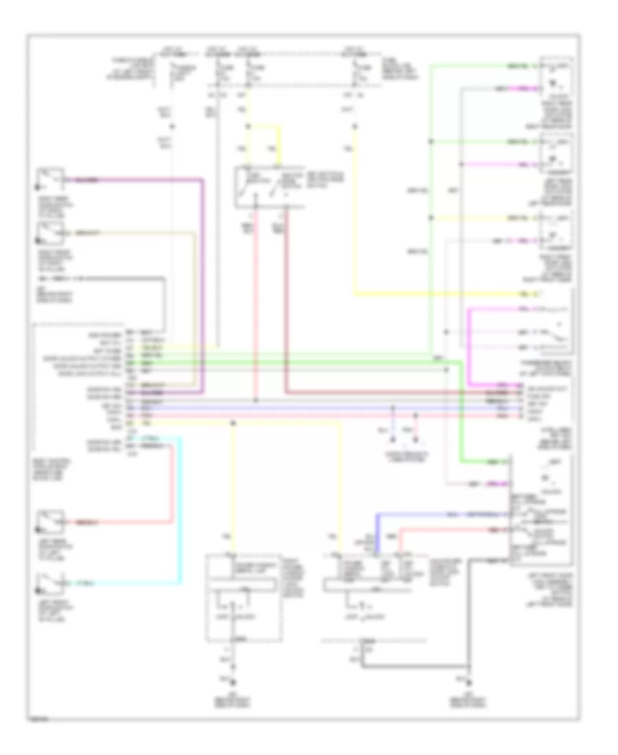
POWER MIRRORS
Power Mirrors Wiring Diagram for Nissan Maxima SL 2008
List of elements for Power Mirrors Wiring Diagram for Nissan Maxima SL 2008:
- 12p
- Auto anti- dazzling inside mirror
- Changeover switch
- Defogger system
- Door mirror remote control switch
- Down
- Fuse 14 10a
- Fuse 19 10a
- Fuse 6 10a
- Fuse block (j/b) (behind left side of dash)
- Hot at all times
- Hot in on or acc
- Hot in on or start
- Illumi- nation
- Interior lights system
- Left
- Left door mirror (at mirror)
- Left/right motor
- M57 (behind right side of dash)
- Mirror switch
- Off
- Right
- Right door mirror (at mirror)
- Up/down motor
- W/ auto dimming outside mirrors
POWER SEATS
Heated Seats Wiring Diagram, with Rear Heated Seats (1 of 2) for Nissan Maxima SL 2008
List of elements for Heated Seats Wiring Diagram, with Rear Heated Seats (1 of 2) for Nissan Maxima SL 2008:
- (at right "b" pillar) b117
- 2p m4
- B117 (at right "b" pillar)
- B7 (at left "b" pillar)
- Cpu
- E121
- E122
- E124
- E24 (at right side of engine compt)
- Fuse & fusible link box (at left front of engine compt)
- Fuse 10a
- Fuse 15a
- Fuse block (j/b) (behind left side of dash)
- Heated seat relay (at right kick panel)
- High
- Hot at all times
- Hot in on or start
- Illum
- Interior lights system
- Ipdm e/r (intelligent power distribution module engine room) (at right front of engine compt)
- Left front heated seat switch
- Left front seat heater
- Low
- M57 (behind right side of dash)
- Off
- Pnk
- Right front heated seat switch
- Right front seat heater
- Tail lamp relay
Heated Seats Wiring Diagram, with Rear Heated Seats (2 of 2) for Nissan Maxima SL 2008
List of elements for Heated Seats Wiring Diagram, with Rear Heated Seats (2 of 2) for Nissan Maxima SL 2008:
- B117 (at right "b" pillar)
- High
- Illum
- Interior lights system
- Left rear heated seat switch
- Left rear seat heater (under left rear seat)
- Low
- Off
- Right rear heated seat switch
- Right rear seat heater (under right rear seat)
Heated Seats Wiring Diagram, without Rear Heated Seats for Nissan Maxima SL 2008
List of elements for Heated Seats Wiring Diagram, without Rear Heated Seats for Nissan Maxima SL 2008:
- (at right "b" pillar) b117
- 2p m4
- B117 (at right "b" pillar)
- B7 (at left "b" pillar)
- Cpu
- E121
- E122
- E124
- E24 (at right side of engine compt)
- Fuse & fusible link box (at left front of engine compt)
- Fuse 10a
- Fuse 15a
- Fuse block (j/b) (behind left side of dash)
- Heated seat relay (at right kick panel)
- High
- Hot at all times
- Hot in on or start
- Illum
- Interior lights system
- Ipdm e/r (intelligent power distribution module engine room) (at right front of engine compt)
- Left front heated seat switch
- Left front seat heater
- Low
- M57 (behind right side of dash)
- Off
- Pnk
- Right front heated seat switch
- Right front seat heater
- Tail lamp relay
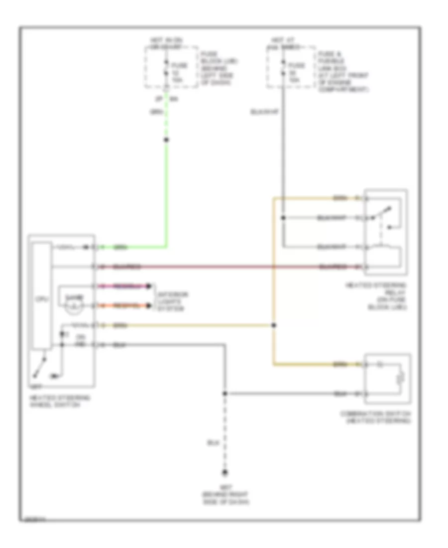
Heated Steering Wheel Wiring Diagram for Nissan Maxima SL 2008
List of elements for Heated Steering Wheel Wiring Diagram for Nissan Maxima SL 2008:
- 2p m4
- Combination switch (heated steering)
- Cpu
- Fuse & fusible link box (at left front of engine compartment)
- Fuse 10a
- Fuse block (j/b) (behind left side of dash)
- Heated steering relay (on fuse block (j/b))
- Heated steering wheel switch
- Hot at all times
- Hot in on or start
- Illum
- Interior
- Lights system
- M57 (behind right side of dash)
- Off
- On ind
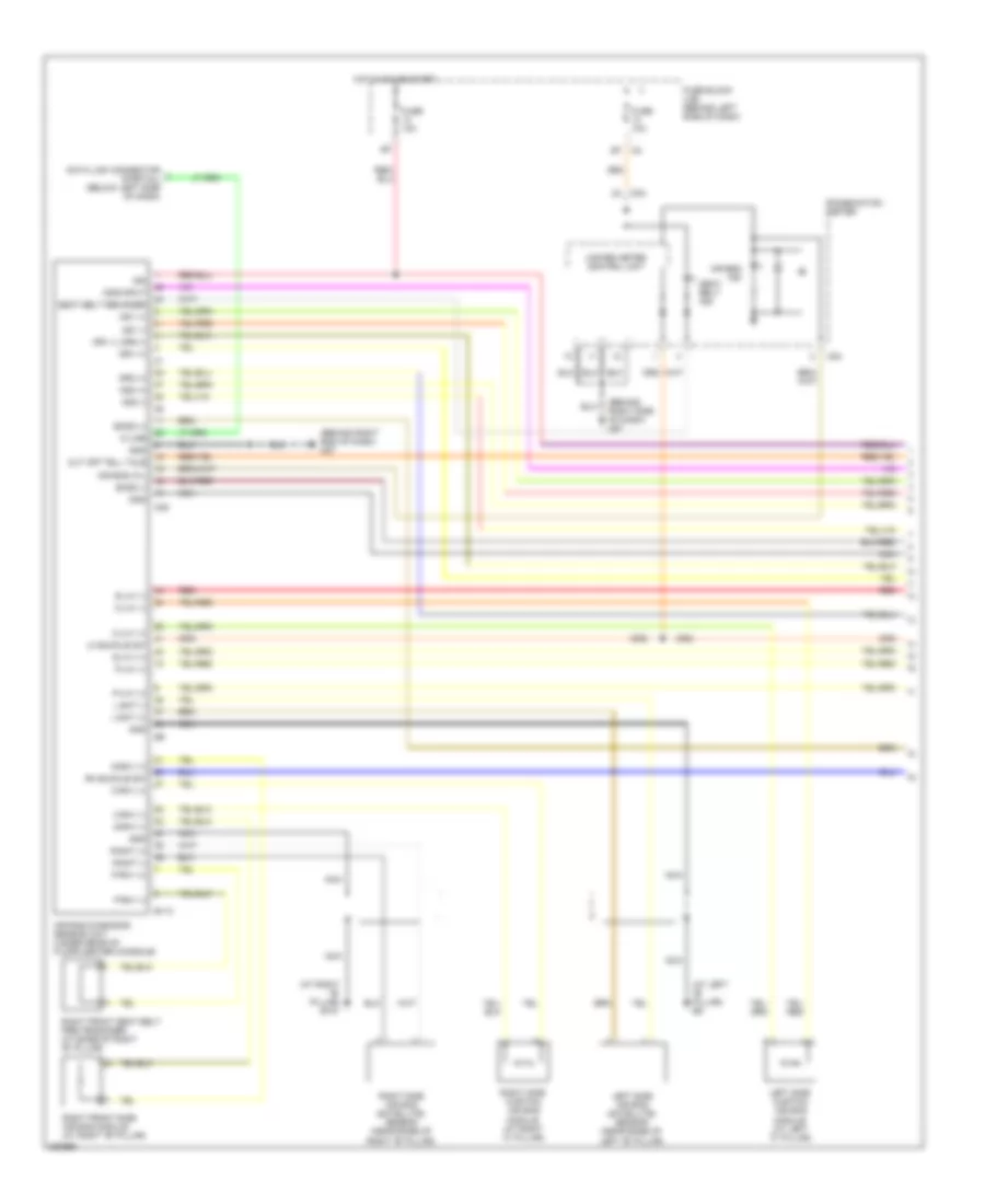
Power Seats Wiring Diagram for Nissan Maxima SL 2008
List of elements for Power Seats Wiring Diagram for Nissan Maxima SL 2008:
- (at right "b" pillar)
- (behind right side of dash) m57
- B117
- B7 (at left "b" pillar)
- Back- ward
- Bat (fil)
- Body control module (bcm) (near fuse block (j/b))
- Bwd
- Down
- For- ward
- Front lifting motor
- Front lifting switch
- Fuse & fusible link box (at left front of engine compt)
- Fusible link f 50a
- Fwd
- Gnd (pwr)
- Hot at all times
- Left lumbar motor
- Left lumbar switch
- Left power seat switch
- Left reclining motor
- Left reclining switch
- Left sliding motor
- Left sliding switch
- M20
- Pwr sply (bat)
- Pwr window
- Rear lifting motor
- Rear lifting switch
- Red
- Right power seat switch
- Right reclining motor
- Right reclining switch
- Right sliding motor
- Right sliding switch
POWER TOP/SUNROOF
Power Top/Sunroof Wiring Diagram for Nissan Maxima SL 2008
List of elements for Power Top/Sunroof Wiring Diagram for Nissan Maxima SL 2008:
- Bat
- Bat (f/l)
- Body control module (bcm) (near fuse block (j/b))
- Cpu
- Door sw (as)
- Door sw (dr)
- Encoder
- Fuse & fusible link box (at left front of engine compartment)
- Fuse 1 10a
- Fuse block (j/b) (behind left side of dash)
- Fusible link f 50a
- Gnd (power)
- Hot at all times
- Hot in on or start
- Ign sw
- Left front door switch (at left "b" pillar)
- M18
- M19
- M20
- M4 15p
- M57 (behind right side of dash)
- M79 (behind right end of dash)
- Pre-select switch
- Rap
- Red
- Right front door switch (at right "b" pillar)
- Slide limit sw
- Sun roof motor (at center front of roof)
- Sun roof switch
- Tilt limit sw
- Tilt switch
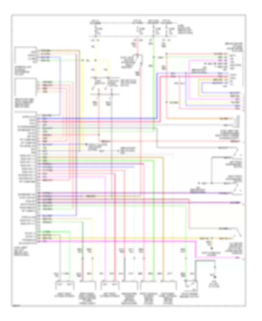
POWER WINDOWS
Power Windows Wiring Diagram, with Driver Side Anti-Pinch System (1 of 2) for Nissan Maxima SL 2008
List of elements for Power Windows Wiring Diagram, with Driver Side Anti-Pinch System (1 of 2) for Nissan Maxima SL 2008:
- (behind right side of dash) m57
- 12p m4
- 15p
- Acc sw bus serial link
- Bat
- Between full stroke & n
- Body control module (bcm) (near fuse block (j/b))
- Cpu
- Down
- Encoder
- Encoder power
- Full stroke
- Fuse & fusible link box (at left front of engine compt)
- Fuse 10a
- Fuse block (j/b) (behind left side of dash)
- Fusible link f 50a
- Gnd
- Hot at all times
- Hot in acc or on
- Hot in on or start
- Ign sw
- Illumination
- Key cyl lock sw
- Key cyl unlock sw
- Left front door lock assembly
- Left front power window motor (at center of left front door)
- Limit sw
- Limit switch
- Lock switch
- M18
- M20
- M57 (behind right side of dash)
- Main power window & door lock/unlock switch
- Power window bat
- Power window rap
- Power window serial link
- Pulse
- Rap
- Red
- Right front power window motor (at center of right front door)
- Right power window & door lock/unlock switch
- Unlock switch
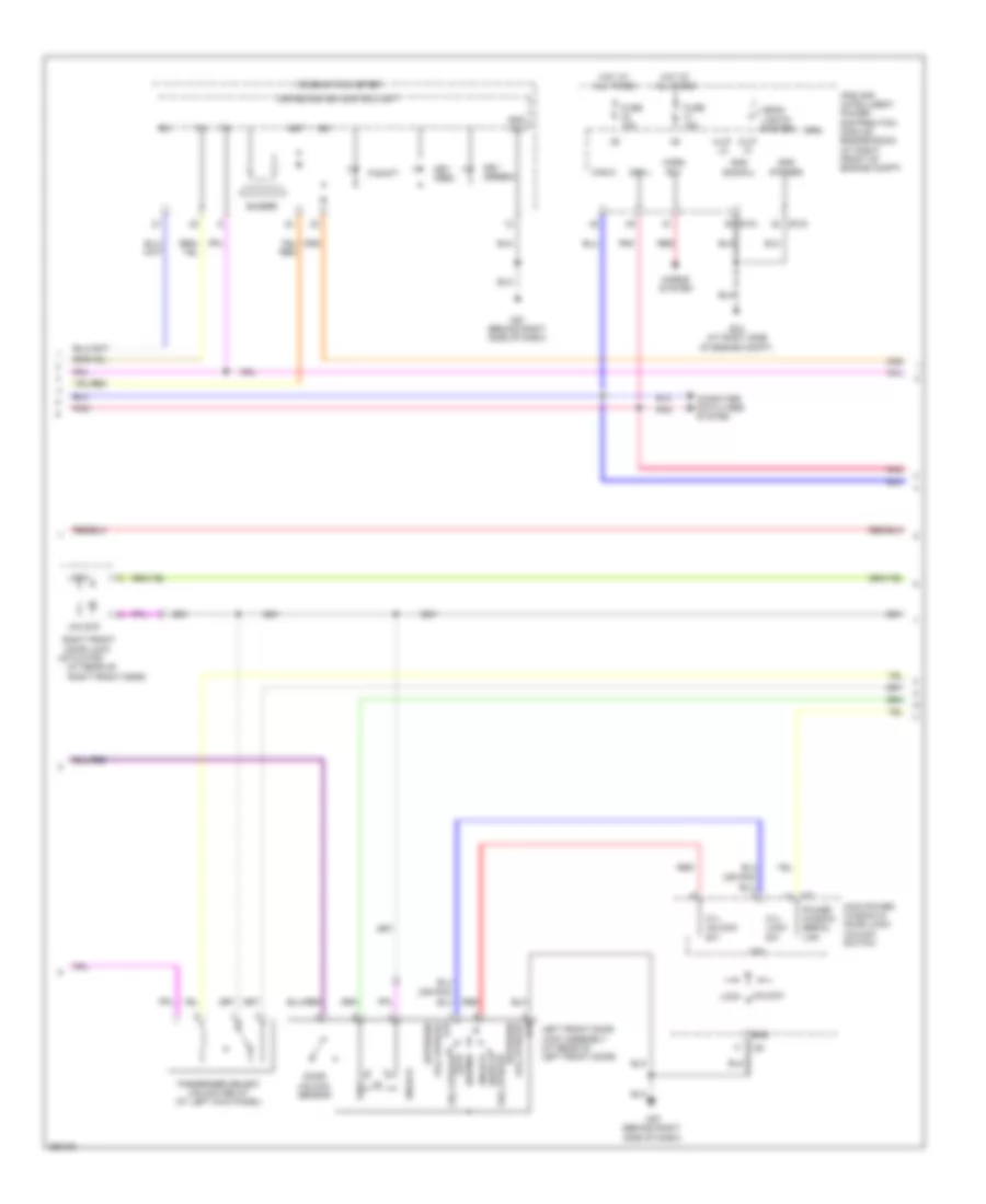
Power Windows Wiring Diagram, with Driver Side Anti-Pinch System (2 of 2) for Nissan Maxima SL 2008
List of elements for Power Windows Wiring Diagram, with Driver Side Anti-Pinch System (2 of 2) for Nissan Maxima SL 2008:
- B117 (at right "b" pillar)
- B7 (at left "b" pillar)
- Bat
- Cpu
- Down
- Encoder
- Encoder power
- Gnd
- Illumination
- Left rear power window motor (at center of left rear door)
- Left rear power window switch
- Limit sw
- Limit switch
- Power window serial link
- Pulse
- Right rear power window motor (at center of right rear door)
- Right rear power window switch
Power Windows Wiring Diagram, with Driver and Passenger Side Anti-Pinch System (1 of 2) for Nissan Maxima SL 2008
List of elements for Power Windows Wiring Diagram, with Driver and Passenger Side Anti-Pinch System (1 of 2) for Nissan Maxima SL 2008:
- 12p m4
- 15p
- Acc sw bus serial link
- B7 (at left "b" pillar)
- Bat
- Between full stroke & n
- Body control module (bcm) (near fuse block (j/b))
- Cpu
- Down
- Encoder
- Encoder power
- Full stroke
- Fuse & fusible link box (at left front of engine compt)
- Fuse 10a
- Fuse block (j/b) (behind left side of dash)
- Fusible link f 50a
- Gnd
- Hot at all times
- Hot in acc or on
- Hot in on or start
- Ign sw
- Illumination
- Key cyl lock sw
- Key cyl unlock sw
- Left front door lock assembly
- Left front power window motor (at center of left front door)
- Left rear power window motor (at center of left rear door)
- Left rear power window switch
- Left rear switch
- Limit sw
- Limit switch
- Lock
- Lock switch
- M18
- M20
- M57 (behind right side of dash)
- Main power window & door lock/unlock switch
- Power window bat
- Power window rap
- Power window serial link
- Pulse
- Rap
- Red
- Right rear switch
- Unlock
- Unlock switch
Power Windows Wiring Diagram, with Driver and Passenger Side Anti-Pinch System (2 of 2) for Nissan Maxima SL 2008
List of elements for Power Windows Wiring Diagram, with Driver and Passenger Side Anti-Pinch System (2 of 2) for Nissan Maxima SL 2008:
- B117 (at right "b" pillar)
- Bat
- Cpu
- Down
- Encoder
- Encoder power
- Gnd
- Illumination
- Limit sw
- Limit switch
- M57 (behind right side of dash)
- Power window & right door lock/unlock switch
- Power window serial link
- Pulse
- Red
- Right front power window motor (at center of right front door)
- Right rear power window motor (at center of right rear door)
- Right rear power window switch
Rear Window Sun Shade Wiring Diagram for Nissan Maxima SL 2008
List of elements for Rear Window Sun Shade Wiring Diagram for Nissan Maxima SL 2008:
- (at right "b" pillar)
- B117
- B117 (at right "b" pillar)
- Down
- Front switch
- Fuse 10a
- Fuse block (j/b) (behind left side of dash)
- Hot in acc or on
- Illumination
- Interior lights system
- M57 (behind right side of dash)
- Rear sunshade
- Rear sunshade rear switch
- Rear sunshade unit (at left "c" pillar)
- Red
RADIO
Radio Wiring Diagram, Base for Nissan Maxima SL 2008
List of elements for Radio Wiring Diagram, Base for Nissan Maxima SL 2008:
- 12p
- Acc
- Ant sig
- Antenna amplifier (behind center of dash)
- Audio unit
- B117 (at right "b" pillar)
- Bat
- C/d
- Can-h
- Can-l
- Combination switch (spiral cable) (in steering column)
- Computer data lines system
- Display unit
- Dn up
- Feeder cable
- Fr lh sp +
- Fr lh sp -
- Fr rh sp +
- Fr rh sp -
- Fuse & fusible link box (at left front of engine compt)
- Fuse 31 20a
- Fuse 4 10a
- Fuse 6 10a
- Fuse block (j/b) (behind left side of dash)
- Gnd
- Hot at all times
- Hot in acc or on
- Led (+)
- Led gnd
- Left front door speaker
- Left rear door speaker
- Left subwoofer
- Left tweeter
- Lh sp in (+)
- Lh sp in (-)
- M102
- M30
- M43
- M51
- M53
- M60
- M63
- Mode switch
- Nca
- Off
- Pnk
- Power switch
- Red
- Reset
- Rh sp in (+)
- Rh sp in (-)
- Right front door speaker
- Right rear door speaker
- Right subwoofer
- Right tweeter
- Rr lh sp +
- Rr lh sp -
- Rr rh sp +
- Rr rh sp -
- Seek switch
- Sht
- Steering wheel audio control switches
- Strg sw a (up)
- Strg sw b (down)
- Strg sw c (gnd)
- Subwoofer amplifier (at left "c" pillar)
- Vee (+)
- Volume switch
- Voo (+)
- W/ navigation
- W/o navigation
- Window antenna
- Woofer 1 (+)
- Woofer 1 (-)
- Woofer 2 (+)
- Woofer 2 (-)
Radio Wiring Diagram, Bose with Navigation (1 of 3) for Nissan Maxima SL 2008
List of elements for Radio Wiring Diagram, Bose with Navigation (1 of 3) for Nissan Maxima SL 2008:
- (rear of roof) (w/ satellite radio tuner) satellite radio antenna
- Acc
- Amp on/off sig
- Ant sig
- Antenna amplifier (behind center of dash)
- Audio unit
- Aux gnd
- Aux in jack
- Aux lh +
- Aux rh +
- B137
- B139
- Backup
- Bat (back up)
- Common -
- Data earth
- Data gnd
- Earth (sig)
- Feeder cable
- Frsp lh (+)
- Frsp lh (-)
- Frsp rh (+)
- Frsp rh (-)
- Gnd
- L (+)
- L (-)
- L +
- M109
- M43
- M44
- M45
- Nca
- Pre-wiring for satellite radio tuner (w/ pre-wiring for satellite radio tuner) satellite radio tuner (w/ satellite radio tuner) (w/ satellite radio tuner: under rear parcel shelf)
- R (+)
- R (-)
- R +
- Red
- Req
- Req1
- Rrsp lh (+)
- Rrsp lh (-)
- Rrsp rh (+)
- Rrsp rh (-)
- Rx (ddcu-aud)
- Rxd
- Sat lch (+)
- Sat lch (-)
- Sat rch (+)
- Sat rch (-)
- Tx (aud-dcu)
- Txd
- W/ satellite radio tuner
- Window antenna
Radio Wiring Diagram, Bose with Navigation (2 of 3) for Nissan Maxima SL 2008
List of elements for Radio Wiring Diagram, Bose with Navigation (2 of 3) for Nissan Maxima SL 2008:
- & a/c amplifier
- (behind center
- 12p
- 13p
- Acc
- Aud shield
- Aud-dcu
- Bus +
- Bus -
- Bus gnd
- Bus shield
- Can-h
- Can-l
- Computer
- Computer data lines system
- Data lines
- Dcu-aud
- Dcu-dsp
- Display control unit (behind center of dash)
- Display unit
- Dsp-dcu
- Fuse 12 10a
- Fuse 3 10a
- Fuse 6 10a
- Fuse block (j/b) (behind left side of dash)
- Gnd
- Hot at all times
- Hot in acc or on
- Hot in on or start
- Ign
- Inv gnd
- Inv vcc
- M49
- M50
- M57 (behind right side of dash)
- M94
- M95
- Nca
- Of dash)
- Pnk
- Red
- Rgb gnd
- Rgb sync
- Sign gnd
- Sign vcc
- Speed (8p)
- Sync gnd
- System
- Unified meter
Radio Wiring Diagram, Bose with Navigation (3 of 3) for Nissan Maxima SL 2008
List of elements for Radio Wiring Diagram, Bose with Navigation (3 of 3) for Nissan Maxima SL 2008:
- (at right "b" pillar) b117
- (phone/ send) sw
- Acc
- Amp on
- Amp on/off sig
- Audio out 1
- Audio out 2
- Av switch
- B117 (at right "b" pillar)
- B127
- B128
- B41
- Bose speaker amplifier (under rear parcel shelf)
- Bus +
- Bus -
- Combination switch (spiral cable) (in steering column)
- End) sw (phone/ mode
- Frsp lh (+) in
- Frsp lh (+) out
- Frsp lh (-) in
- Frsp lh (-) out
- Frsp rh (+) in
- Frsp rh (+) out
- Frsp rh (-) in
- Frsp rh (-) out
- Fuse & fusible link box (at left front of engine compartment)
- Fuse 18 15a
- Fuse 31 20a
- Fuse block (j/b) (behind left side of dash)
- Gnd
- Hot at all times
- Ill
- Ill cont
- Input (+)
- Input (-)
- Interior lights system
- Ladder gnd
- Ladder in 1
- Ladder in 2
- Ladder in gnd
- Left front door speaker
- Left rear door speaker
- Left subwoofer
- Left tweeter
- M102
- M30
- M61 (behind right side of dash)
- Nca
- Off
- Power
- Power gnd
- Red
- Right front door speaker
- Right rear door speaker
- Right subwoofer
- Right tweeter
- Rrsp lh (+) in
- Rrsp lh (+) out
- Rrsp lh (-) in
- Rrsp lh (-) out
- Rrsp rh (+) in
- Rrsp rh (+) out
- Rrsp rh (-) in
- Rrsp rh (-) out
- Shield
- Steering wheel audio control switches
- Strg sw a (up)
- Strg sw b (down)
- Strg sw c (gnd)
- Sw seek
- Sw volume
- Woofer amp on
- Woofer out (+)
- Woofer out (-)
Radio Wiring Diagram, Bose without Navigation (1 of 2) for Nissan Maxima SL 2008
List of elements for Radio Wiring Diagram, Bose without Navigation (1 of 2) for Nissan Maxima SL 2008:
- (rear of roof) (w/ satellite radio tuner) satellite radio antenna
- 12p
- Acc
- Amp on/off sig
- Ant sig
- Antenna amplifier (behind center of dash)
- Audio unit
- B137
- B139
- Backup
- Bat
- C/d
- Can-h
- Can-l
- Computer data lines system
- Data earth
- Display unit
- Earth (sig)
- Feeder cable
- Fr lh sp (+)
- Fr lh sp (-)
- Fr rh sp (+)
- Fr rh sp (-)
- Fuse & fusible link box (at left front of engine compt)
- Fuse 31 20a
- Fuse 6 10a
- Fuse block (j/b) (behind left side of dash)
- Gnd
- Hot at all times
- Hot in acc or on
- L (+)
- L (-)
- Led +
- Led gnd
- M109
- M51
- M53
- M60
- M63
- Nca
- Pnk
- Pre-wiring for satellite radio tuner (w/ pre-wiring for satellite radio tuner) satellite radio tuner (w/ satellite radio tuner) (w/ satellite radio tuner: under rear parcel shelf)
- R (+)
- R (-)
- Red
- Req
- Req1
- Reset
- Rr lh sp (+)
- Rr lh sp (-)
- Rr rh sp (+)
- Rr rh sp (-)
- Rxd
- Sat lch (+)
- Sat lch (-)
- Sat rch (+)
- Sat rch (-)
- Shield 2
- Sht
- Strg sw a (up)
- Strg sw b (down)
- Strg sw c (gnd)
- Txd
- Vee +
- Vvo +
- W/ satellite radio tuner
- Window antenna
Radio Wiring Diagram, Bose without Navigation (2 of 2) for Nissan Maxima SL 2008
List of elements for Radio Wiring Diagram, Bose without Navigation (2 of 2) for Nissan Maxima SL 2008:
- (at right "b" pillar) b117
- Amp on
- Amp on/off sig
- B117 (at right "b" pillar)
- B127
- B128
- B41
- Bose speaker amplifier (under rear parcel shelf)
- Combination switch (spiral cable)
- Frsp lh (+) in
- Frsp lh (+) out
- Frsp lh (-) in
- Frsp lh (-) out
- Frsp rh (+) in
- Frsp rh (+) out
- Frsp rh (-) in
- Frsp rh (-) out
- Fuse 18 15a
- Fuse block (j/b) (behind left side of dash)
- Gnd
- Hot at all times
- Input (+)
- Input (-)
- Ladder gnd
- Ladder in 1
- Ladder in 2
- Ladder in gnd
- Ladder out 1
- Ladder out 2
- Left front door speaker
- Left rear door speaker
- Left subwoofer
- Left tweeter
- M102
- M30
- Mode (phone/ end) switch
- Mode switch
- Nca
- Off
- Power (phone/ send) switch
- Power gnd
- Power switch
- Red
- Right front door speaker
- Right rear door speaker
- Right subwoofer
- Right tweeter
- Rrsp lh (+) in
- Rrsp lh (+) out
- Rrsp lh (-) in
- Rrsp lh (-) out
- Rrsp rh (+) in
- Rrsp rh (+) out
- Rrsp rh (-) in
- Rrsp rh (-) out
- Seek dn switch
- Steering wheel audio control switches
- Volume dn switch
- Woofer amp on
- Woofer out (+)
- Woofer out (-)
SHIFT INTERLOCK
Shift Interlock Wiring Diagram for Nissan Maxima SL 2008
List of elements for Shift Interlock Wiring Diagram for Nissan Maxima SL 2008:
- 14p
- 8p/r
- A/t device (under center console)
- Bat (+)
- Detent sw (key)
- Detent sw (shift)
- Detent switch (key)
- Detent switch (shift)
- E30
- Fuse 10a
- Fuse block (j/b) (behind left side of dash)
- Gnd
- Hot at all times
- Hot in on or start
- Ign sw
- Ignition knob switch
- Key lock sol out
- Key lock solenoid
- Key switch & ignition knob switch (on steering column)
- M50
- M57 (behind right side of dash)
- Red
- Shift lock control unit (near fuse block (j/b))
- Shift lock sol out
- Shift lock solenoid
- Stop lamp sw
- Stop lamp switch (on brake pedal bracket)
- Unified meter & a/c amplifier (behind center of dash)
- Vsp sig
STARTING/CHARGING
Charging Wiring Diagram for Nissan Maxima SL 2008
List of elements for Charging Wiring Diagram for Nissan Maxima SL 2008:
- Battery
- Charge indicator
- Combination meter
- E116 (at right side of engine compt)
- Fuse & fusible link box (at left front of engine compt)
- Fuse 10a
- Fuse block (j/b) (behind left side of dash)
- Fusible link a 120a
- Fusible link box (battery)
- Generator
- Hot at all times
- Hot in on or start
- Nca
- Starting circuit
Starting Wiring Diagram for Nissan Maxima SL 2008
List of elements for Starting Wiring Diagram for Nissan Maxima SL 2008:
- Acc
- Battery
- Can-h
- Can-l
- Computer data lines system
- Cpu
- Cvt unit (left rear of engine)
- E119
- E121
- E24 (at right side of engine compt)
- F30
- F56
- F57
- Fuse & fusible link box (at left front of engine compt)
- Fusible link box (battery)
- Fusible link m 40a
- Hot at all times
- Ignition switch
- Inh sw1
- Inh sw2
- Inh sw3
- Inh sw3 mon
- Inh sw4
- Inhib sw
- Ipdm e/r (at right front of engine compt)
- Nca
- Off
- Park/ neutral position switch
- Pnk
- Start
- Starter motor
- Starter relay
- Starter rly
- Transmission control module (tcm) (behind right side of dash)
SUPPLEMENTAL RESTRAINTS
Supplemental Restraints Wiring Diagram (1 of 2) for Nissan Maxima SL 2008
List of elements for Supplemental Restraints Wiring Diagram (1 of 2) for Nissan Maxima SL 2008:
- (at left "b" pillar) b5
- (at right "b" pillar) b107
- (behind right end of dash) m57
- (behind right side of dash) m57
- Air bag diagnosis sensor unit (under rear of floor center console)
- Air bag ind
- Air bag w/l
- As1 (+)
- As1 (-)
- As2 (+)
- As2 (-)
- B113
- C-lh1 (+)
- C-lh1 (-)
- C-rh1 (+)
- C-rh1 (-)
- Combination meter
- Cut off tell tale
- Data link connector (partial) (below left side of dash)
- Dr1 (+)
- Dr1 (-), dr2 (-)
- Dr2 (+)
- Eczs (+)
- Eczs (-)
- Fuse 10a
- Fuse block (j/b) (behind left side of dash)
- Gnd
- Hot in on or start
- Ign
- K-line
- L-sat (+)
- L-sat (-)
- Left side air bag (satellite) sensor (near base of left "b" pillar)
- Left side curtain air bag module (at left "c" pillar)
- Lh buckle sw
- M24
- M35
- Nca
- Ods-input
- P-lh1 (+)
- P-lh1 (-)
- P-rh1 (+)
- P-rh1 (-)
- R-sat (+)
- R-sat (-)
- Red
- Rh buckle sw
- Right front seat belt pre-tensioner (at base of right "b" pillar)
- Right front side air bag module (at right "b" pillar)
- Right side air bag (satellite) sensor (near base of right "b" pillar)
- Right side curtain air bag module (at right "c" pillar)
- S-lh1 (+)
- S-lh1 (-)
- S-rh1 (+)
- S-rh1 (-)
- Seat belt ind
- Seat belt reminder
- Unified meter control unit
Supplemental Restraints Wiring Diagram (2 of 2) for Nissan Maxima SL 2008
List of elements for Supplemental Restraints Wiring Diagram (2 of 2) for Nissan Maxima SL 2008:
- (+)
- (-)
- (at left "c" pillar) b19
- (at left side of engine compartment) e14
- (at right "b" pillar) b117
- (behind right side of dash) m57
- Belt tension sensor (under right front seat)
- Bts (+)
- Bts (-)
- Bts sig
- Crash zone sensor (center front of engine compt)
- Driver air bag module
- Fastened
- Front passenger air bag module
- Front passenger air bag off indicator
- Gnd
- Ign
- Left front seat belt pre-tensioner (at base of left "b" pillar)
- Left front side air bag module (at left "b" pillar)
- Left seat belt buckle switch (inside left front seat belt buckle)
- M101
- M103
- Nca
- Occupant classification system control unit (behind right side of dash)
- Occupant classification system sensor (in right front seat cushion)
- Ods-led
- Red
- Right seat belt buckle switch (inside right front seat belt buckle)
- Sig
- Spiral cable
- Un- fastened
TRANSMISSION
A/T Wiring Diagram for Nissan Maxima SL 2008
List of elements for A/T Wiring Diagram for Nissan Maxima SL 2008:
- At-p range
- Atf temp sen
- Auto
- Auto mode sw
- Batt
- Can-h
- Can-l
- Chip select
- Clock
- Combination meter
- Computer data lines system
- Cvt device (under center console)
- Cvt fluid temp sensor
- Cvt ind
- Cvt unit (left rear of engine)
- Data i/o
- Dwn
- Ecm
- Engine control module (behind right side of dash)
- Exterior lights system
- Fuse 10a
- Fuse 15a
- Fuse block (j/b) (behind left side of dash)
- Gnd
- Hot at all times
- Hot in on or start
- Ign
- Inh sw1
- Inh sw2
- Inh sw3
- Inh sw3 mon
- Inh sw4
- Ipdm e/r (intelligent power distribution module engine room) (right front of engine compt)
- Lck-up sel sol
- Line press sol
- Line pressure solenoid valve
- Lock-up select solenoid valve
- M57 (behind right side of dash)
- M61 (behind right side of dash)
- Man
- Manual mode sw
- Mode select switch
- Neut
- Park/ neutral position switch
- Pnk
- Position select switch
- Power gnd
- Prim press sen
- Prim speed sen
- Primary pressure sensor
- Primary speed sensor
- Red
- Rev lamp relay
- Rom assembly
- S/m a
- S/m b
- S/m c
- S/m d
- Sec press sen
- Sec press sol
- Sec speed sen
- Secondary pressure sensor
- Secondary pressure solenoid valve
- Secondary speed sensor (top of transaxle)
- Sensor gnd
- Sensor pwr (5v)
- Shift dn sw
- Shift up sw
- Starter relay
- Starting/ charging system
- Step motor
- Tcc sol
- Torque converter clutch solenoid valve
- Transmission control module (tcm) (behind right side of dash)
- Unified meter & a/c amplifier (behind center of dash)
- Unified meter control unit
- Vign
TRUNK, TAILGATE, FUEL DOOR
Trunk & Fuel Door Release Wiring Diagram for Nissan Maxima SL 2008
List of elements for Trunk & Fuel Door Release Wiring Diagram for Nissan Maxima SL 2008:
- B7 (at left ``b" pillar)
- Bat
- Body control module (bcm) (near fuse block (j/b))
- Door locks system
- Fuel lid opener actuator (in left rear fender)
- Fuse & fusible link box (at left front of engine compt)
- Fuse 10a
- Fuse block (j/b) (behind left side of dash)
- Fusible link f 50a
- Hot at all times
- M18
- M20
- M57 (behind right side of dash)
- M61 (behind right side of dash)
- Red
- Trunk & fuel lid opener switch
- Trunk lid opener cancel switch
- Trunk lid switch & trunk release solenoid (trunk lid switch: at rear center of luggage lid) (trunk relese solenoid: at center rear of luggage compt lid)
- Trunk opener out m19
- Trunk sw
WARNING SYSTEMS
Warning Systems Wiring Diagram for Nissan Maxima SL 2008
List of elements for Warning Systems Wiring Diagram for Nissan Maxima SL 2008:
- 14p
- 15p
- Air bag diagnosis sensor unit (under rear of floor center console)
- B7 (at left "b" pillar)
- Bat (f/l)
- Body control module (bcm) (near fuse block (j/b))
- Buckle sw
- Buzzer
- Can-h
- Can-l
- Combi sw input 1
- Combi sw input 2
- Combi sw input 3
- Combi sw input 4
- Combi sw input 5
- Combi sw output 1
- Combi sw output 2
- Combi sw output 3
- Combi sw output 4
- Combi sw output 5
- Combination meter
- Combination switch
- Computer data lines system
- Door ind
- Door sw (dr)
- Fuse & fusible link box (at left front of engine compartment)
- Fuse 10a
- Fuse block (j/b) (behind left side of dash)
- Fusible link f 50a
- Gnd
- Hot at all times
- Hot in on or start
- Ign sw
- Input 1
- Input 2
- Input 3
- Input 4
- Input 5
- Key sw
- Key switch & ignition knob switch
- Left front door switch (at left "b" pillar)
- Left seat belt buckle switch
- M18
- M19
- M20
- M35
- M49
- M57 (behind right side of dash)
- Output 1
- Output 2
- Output 3
- Output 4
- Output 5
- Pnk
- Red
- Seat belt ind
- Unified meter & a/c amplifier (behind center of dash)
- Unified meter control unit
WIPER/WASHER
Wiper/Washer Wiring Diagram for Nissan Maxima SL 2008
List of elements for Wiper/Washer Wiring Diagram for Nissan Maxima SL 2008:
- 15p
- Bat
- Body control module (bcm) (near fuse block (j/b))
- Can-h
- Can-l
- Combination meter
- Combination switch (front wiper switch)
- Cpu
- E121 pnk
- E122
- E124
- E15 (at left side of engine compt)
- Fr washer motor
- Front washer motor (in washer reservoir)
- Front wiper hi relay
- Front wiper motor (on left side of firewall)
- Front wiper relay
- Fuse & fusible link box (at left front of engine compt)
- Fuse 10a
- Fuse 20a
- Fuse block (j/b) (behind left side of dash)
- Fusible link f 50a
- Gnd
- High
- Hot at all times
- Hot in on or start
- Ign sw
- Ignition relay
- Input 1
- Input 2
- Input 3
- Input 4
- Input 5
- Ipdm e/r (at right front of engine compt)
- Low
- M18
- M19
- M28
- M57 (behind right side of dash)
- Move
- Output 1
- Output 2
- Output 3
- Output 4
- Output 5
- Pnk
- Red
- Stop
- Washer fluid level switch (in washer reservoir)
- Washer ind

 Čeština
 Dansk
Dansk Deutsch
 Ελληνικά
 English
 Español
 Suomi
Suomi Français
 Français
 עברית
עברית Hrvatski
 Magyar
 Italiano
 日本語
日本語 한국어
한국어 Nederlands
 Polski
 Português
 Português
 Română
 Русский
 Slovenčina
 Slovenščina
 Svenska
 Türkçe
 中文 (中国)