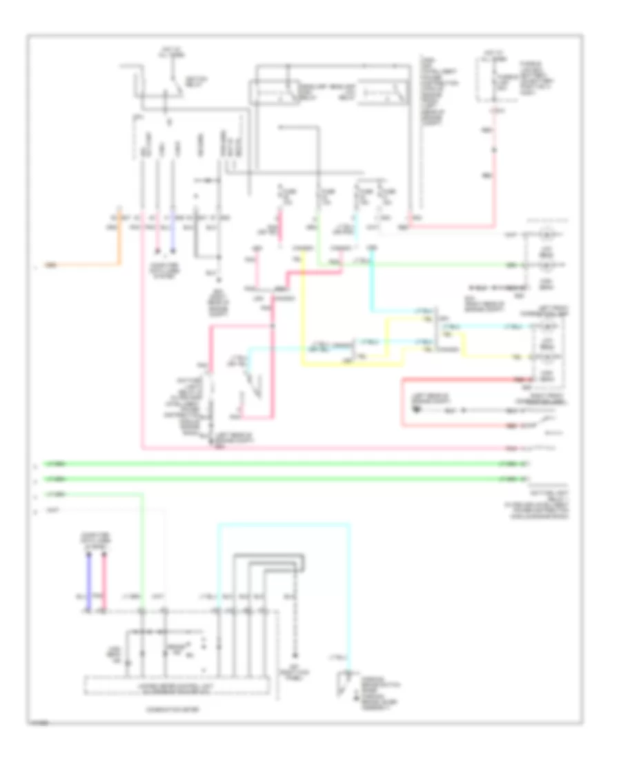
AIR CONDITIONING
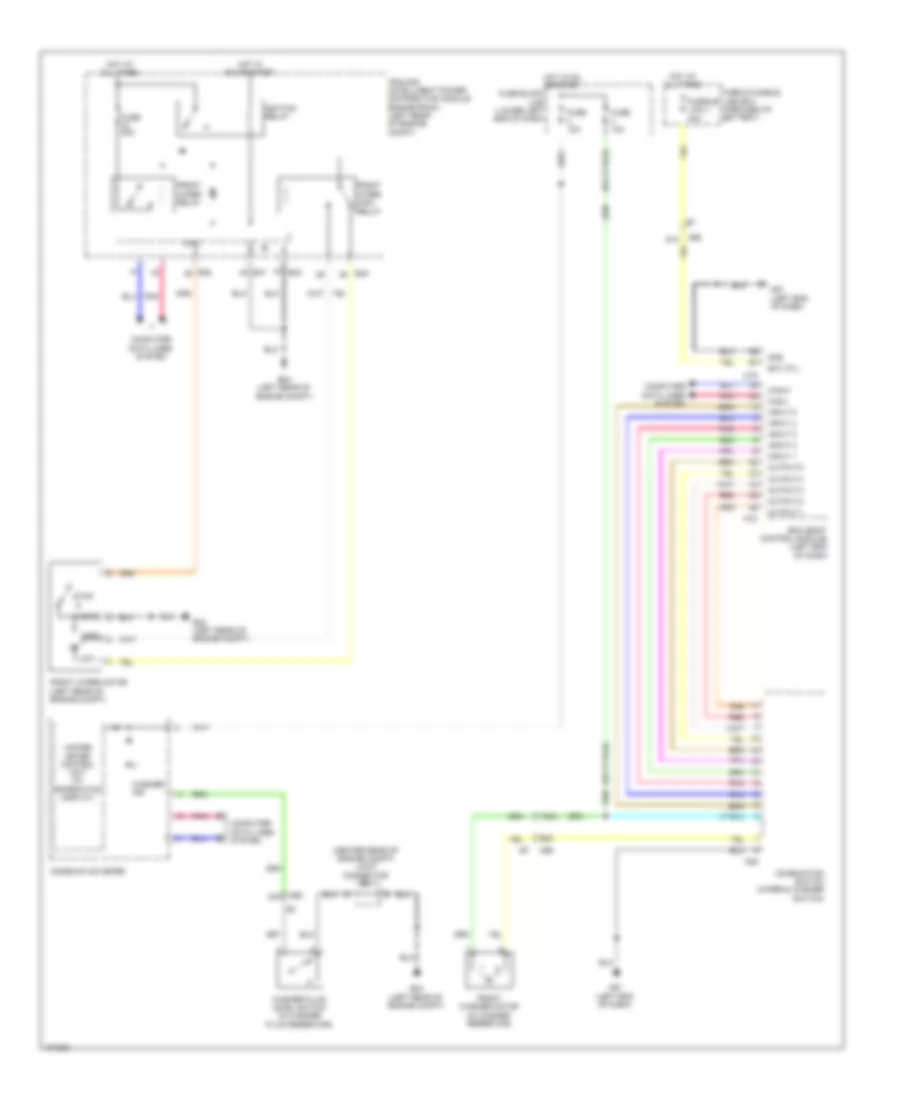
Manual A/C Wiring Diagram (1 of 2) for Nissan NV200 S 2013
 https://portal-diagnostov.com/license.html
Automotive Electricians Portal FZCO
Automotive Electricians Portal FZCO
https://portal-diagnostov.com/license.html
https://portal-diagnostov.com/license.html
Automotive Electricians Portal FZCO
Automotive Electricians Portal FZCO
List of elements for Manual A/C Wiring Diagram (1 of 2) for Nissan NV200 S 2013:
- 40b
- A/c compressor (lower left front of engine)
- A/c on indicator
- A/c switch
- Acc
- Air con ind output
- Air con sw
- Blower fan sw
- Blower relay
- Body control module (left end of dash)
- Can-h
- Can-l
- Computer data lines system
- Defogger system
- E11
- Fan switch
- Front air control
- Front blower motor (right side of a/c unit)
- Front blower motor resistor (lower left side of a/c unit)
- Fuse 10a
- Fuse 15a
- Fuse block j/b (lower left end of dash)
- Fusible link box (battery) (on battery positive (+) post)
- Fusible link d 60a
- Fusible link e 80a
- Hot at all times
- Hot in on or start
- Ig2
- Ignition switch
- Interior lights system
- M18
- M19
- M61 (left end of dash)
- M78
- Off
- Pnk
- Rear window defogger indicator
- Rear window defogger switch
- Red
- Start
- Thermo amp
Manual A/C Wiring Diagram (2 of 2) for Nissan NV200 S 2013
List of elements for Manual A/C Wiring Diagram (2 of 2) for Nissan NV200 S 2013:
- (or pnk)
- 26a
- A/c relay
- A/c rly
- Avcc2
- Can-h
- Can-l
- Computer data lines system
- Cooling fan motor 1 (behind left side of radiator)
- Cooling fan motor 2 (behind right side of radiator)
- Cooling fan relay 1
- Cooling fan relay 2
- Cooling fan relay 3
- Cooling fan relay 4 (in ipdm e/r (intelligent power power distribution module engine room))
- Cooling fan relay 5 (in ipdm e/r (intelligent power power distribution module engine room))
- Cpu
- E15 (right rear of engine compt)
- E16
- E24 (left rear of engine compt)
- E42
- E43
- E44
- E45
- E46
- E47
- E48
- E49
- Ecm (left rear of engine compt)
- Ecm relay
- Ecm relay (self shut-off)
- Eng cool temp sens
- Engine controls system
- Engine coolant temperature sensor (rear of cylinder head)
- F10
- F11
- Fuse & fusible link box (forward of battery)
- Fuse 10a
- Fuse 20a
- Fusible link f 40a
- Fusible link g 40a
- Hot at all times
- Hot in on or start
- Ignition relay
- Ipdm e/r (intelligent power distribution module engine room) (left rear of engine compt)
- M61 (left end of dash)
- M69
- Motor fan-rly driver 1
- Motor fan-rly driver 2
- Pdpres
- Pnk
- Power gnd
- Power sply for ecm
- Red
- Refrigerant pressure sensor (bottom right side of condenser)
- Sensor ground
- Thermo control amplifier (right side of a/c unit)
ANTI-LOCK BRAKES
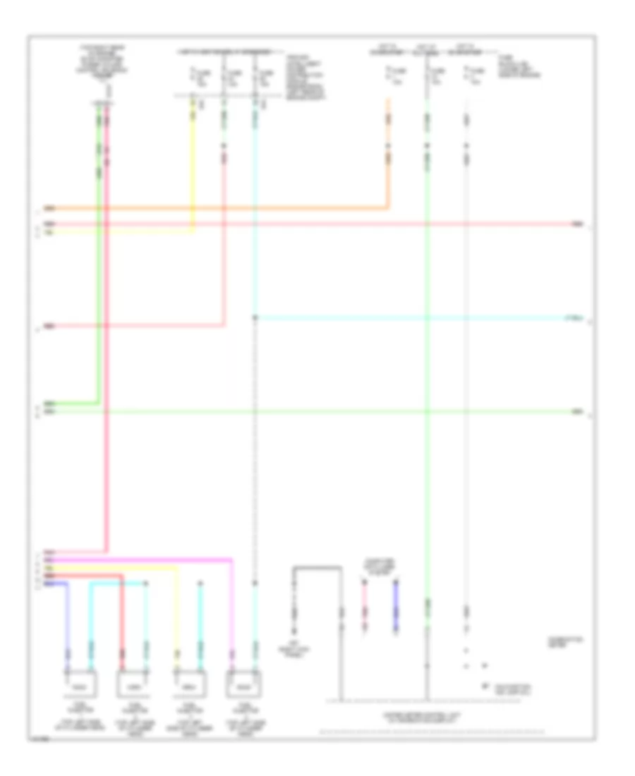
Anti-lock Brakes Wiring Diagram (1 of 2) for Nissan NV200 S 2013
List of elements for Anti-lock Brakes Wiring Diagram (1 of 2) for Nissan NV200 S 2013:
- (right rear of engine compt) e69
- 42a
- 43a
- 44a
- 45a
- 92a
- Abs actuator & electric unit (control unit) (right rear of engine compt)
- Abs/tcs/vdc control unit
- Actuator
- B29
- Bls
- Can-h
- Can-h yrs
- Can-l
- Can-l yrs
- Computer data lines system
- Dia k
- E43
- E69 (right rear of engine compt)
- Fl in
- Fl out
- Fr in
- Fr out
- Fuse & fusible link box (forward of battery)
- Fuse 10a
- Fuse block (j/b) (lower left end of dash)
- Fusible link i 40a
- Fusible link k 30a
- Hot at all times
- Hot in on or start
- Hsv 1
- Hsv 2
- Ign
- Interior lights system
- Ipdm e/r (intelligent power distribution module engine room) (left rear of engine compt)
- J/c e01 (center rear of engine compt)
- Left front wheel sensor (on left front wheel hub assembly)
- Left rear wheel sensor (on left rear wheel hub assembly)
- M gnd
- M12
- M57 (right kick panel)
- M69
- Motor
- Motor relay
- Pnk
- Red
- Relay unit
- Right front wheel sensor (on right front wheel hub assembly)
- Right rear wheel sensor (on right rear wheel hub assembly)
- Rl in
- Rl out
- Rr in
- Rr out
- S gnd
- Solenoid valve relay
- Stoplamp switch (top of brake pedal on bracket)
- Usv1
- Usv2
- Vdc off sw
- Vdc off switch
- Wp fl
- Wp fr
- Wp rl
- Wp rr
- Ws fl
- Ws fr
- Ws rl
- Ws rr
Anti-lock Brakes Wiring Diagram (2 of 2) for Nissan NV200 S 2013
List of elements for Anti-lock Brakes Wiring Diagram (2 of 2) for Nissan NV200 S 2013:
- (on steering column) steering angle sensor
- (rear of center console) yaw rate/side/ decel g-sensor
- (w/ information display) unified meter control unit
- 34a
- 46a
- 48a
- 49a m69
- Abs ind
- Brake fluid level switch (on brake fluid reservoir)
- Brake ind
- Brake oil sw
- Can-h
- Can-l
- Combination meter
- Computer data lines system
- E24 (left rear of engine compt)
- E7 red
- Fuse 10a
- Fuse block (j/b) (lower left end of dash)
- Gnd (circuit)
- Gnd (ill)
- Gnd (power)
- Hot in on or start
- Ign
- J/c e01 (center rear of engine compt)
- M57 (right kick panel)
- M61 (left end of dash)
- M69
- Parking brake switch (base of parking lever assembly)
- Pkb
- Pnk
- Red
- Slip ind
- Vdc off ind
ANTI-THEFT
Forced Entry Wiring Diagram (1 of 2) for Nissan NV200 S 2013
List of elements for Forced Entry Wiring Diagram (1 of 2) for Nissan NV200 S 2013:
- (left rear of engine compt) ipdm e/r (intelligent power distribution module engine room)
- +ig
- Acc sw
- B225
- B250
- B29
- B58
- B65
- Back door switch (lower left side of left back door)
- Bat (f/l)
- Bat (fuse)
- Batt saver output
- Bcm (body control module) (left end of dash)
- Can h
- Can l
- Can-h
- Can-l
- Combination meter
- Computer data lines system
- Cpu
- D500
- D505 (center of left back door)
- Door lock output
- Door lock sw
- Door sw (as)
- Door sw (back)
- Door sw (dr)
- Door sw (rl)
- Door sw (rr)
- Door unlck out (dr)
- Door unlock sw
- Dr unlck out (other)
- E24 (left rear of engine compt)
- E46
- E47
- E48
- Exterior lights system
- Fuse 10a
- Fuse block (j/b) (lower left end of dash)
- Gnd
- Gnd (pwr)
- Gnd (sig)
- H/lp hi
- H/lp lo
- Headlights system
- Horn rly cont
- Horns system
- Hot at all times
- Hot in on or acc
- Hot in on or start
- Ign sw
- Ignition relay
- Ind door
- Interior lights system
- Key cyl lock sw
- Key cyl unlock sw
- Key sw
- Key switch
- Left front door switch (on left "b" pillar)
- Left sliding door switch (on left "b" pillar)
- Lh flasher output
- M12
- M18
- M19
- M20
- M57 (right kick panel)
- M61 (left end of dash)
- Pnk
- Power sply
- Red
- Remote keyless entry receiver (right side of dash)
- Rh flasher output
- Right front door switch (on right "b" pillar)
- Right sliding door switch (on right "b" pillar)
- Room lamp output
- Security ind
- Security ind output
- Sens gnd
- Signal
- Unified meter control unit (w/ information display)
Forced Entry Wiring Diagram (2 of 2) for Nissan NV200 S 2013
List of elements for Forced Entry Wiring Diagram (2 of 2) for Nissan NV200 S 2013:
- (front of left sliding door) left sliding door lock actuator
- (front of right sliding door) right sliding door lock actuator
- 91a
- Actuator
- B23
- B59
- Back door lock actuator (center of left back door)
- Cpu
- D1 m9
- D102
- D115
- D501
- Door lock
- Door unlock
- E18
- E20
- E24 (left rear of engine compt)
- Fuse & fusible link box (forward of battery)
- Fuse 10a
- Fusible link j 40a
- Gnd
- Horn (left front of engine compt)
- Horn relay (in fuse & fusible link box)
- Hot at all times
- Key cylinder switch
- Left front door lock assembly
- Left sliding door contact switch (pillar) (on left "b" pillar)
- Lock
- M15
- M57 (right kick panel)
- M61 (left end of dash)
- M69
- M74
- M81
- Main power window & door lock/ unlock switch
- Pnk
- Red
- Right front door lock actuator
- Right power window & door lock/ unlock switch
- Right sliding door contact switch (pillar) (on right "b" pillar)
- Sliding door contact switch (door) (on left "b" pillar)
- Sliding door contact switch (door) (on right "b" pillar)
- Telematics control module (if equipped) (center of dash)
- Unlock
Immobilizer Wiring Diagram for Nissan NV200 S 2013
List of elements for Immobilizer Wiring Diagram for Nissan NV200 S 2013:
- Audio/dongle line
- Bat (f/l)
- Bcm (body control module) (left end of dash)
- Can-h
- Can-l
- Combi- nation meter
- Computer data lines system
- Dongle unit (canada)
- E45
- Fuse & fusible link & relay box (forward of battery)
- Fuse 10a
- Fuse 20a
- Fuse block (j/b) (lower left end of dash)
- Fusible link j 40a
- Gnd
- Hot at all times
- Hot in on or start
- Ign sw
- Immob one way
- Immob two way
- Ipdm e/r (intelligent power distribution module engine room) (left rear of engine compt)
- M18
- M19
- M61 (left end of dash)
- M69 3a
- M69 91a
- Nats antenna amplifier (at ignition switch assembly)
- Pnk
- Red
- Scrty ind out
- Security ind
BODY CONTROL MODULES
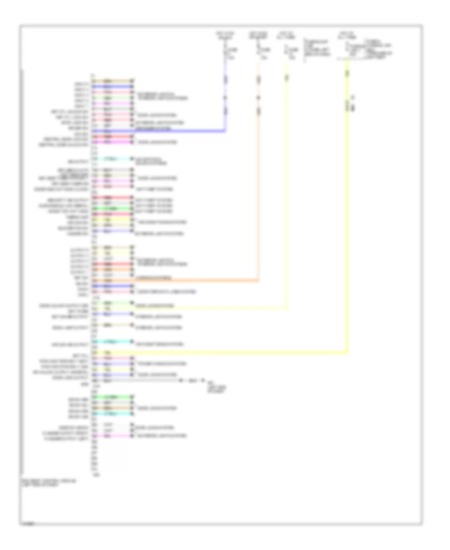
Body Control Modules Wiring Diagram for Nissan NV200 S 2013
List of elements for Body Control Modules Wiring Diagram for Nissan NV200 S 2013:
- 91a
- Acc sw
- Air con ind output
- Air con sw
- Air conditioning system
- Anti-theft system
- Audo/dongle link (serial)
- Bat (f/l)
- Bat (fuse)
- Bat saver output
- Bcm (body control module) (left end of dash)
- Blower fan sw
- Can-h
- Can-l
- Central door lock sw
- Central door unlock sw
- Computer data lines system
- Defogger system
- Door lock output
- Door locks system
- Door sw (back)
- Door unlock output (dr)
- Dr sw (as)
- Dr sw (dr)
- Dr sw (rl)
- Dr sw (rr)
- Dr unlock output (as,rr,rl)
- Exterior lights & interior lights systems
- Exterior lights system
- Flasher output (left)
- Flasher output (right)
- Fuse & fusible link box (forward of battery)
- Fuse 10a
- Fuse block (j/b) (lower left end of dash)
- Fusible link j 40a
- Gnd
- Hazard sw
- Hot at all times
- Hot in on or acc
- Hot in on or start
- Ign sw
- Immob one way comm (clock)
- Immob two way comm
- Input 1
- Input 2
- Input 3
- Input 4
- Input 5
- Interior lights system
- Key cyl lock sw
- Key cyl unlock sw
- Key sw
- Keyless & auto light sens gnd
- Keyless tuner pwr sply
- Keyless tuner sig
- M18
- M19
- M20
- M61 (left end of dash)
- M69
- Mr output
- Navigation & sound systems
- Output 1
- Output 2
- Output 3
- Output 4
- Output 5
- Pnk
- Power windows system
- Pwr wdw pwr sply (bat)
- Pwr wdw pwr sply (ign)
- Red
- Room lamp output
- Rr def sw
- Security ind output
- Stop lamp sw
- Thermo amp
- Warning systems
COMPUTER DATA LINES
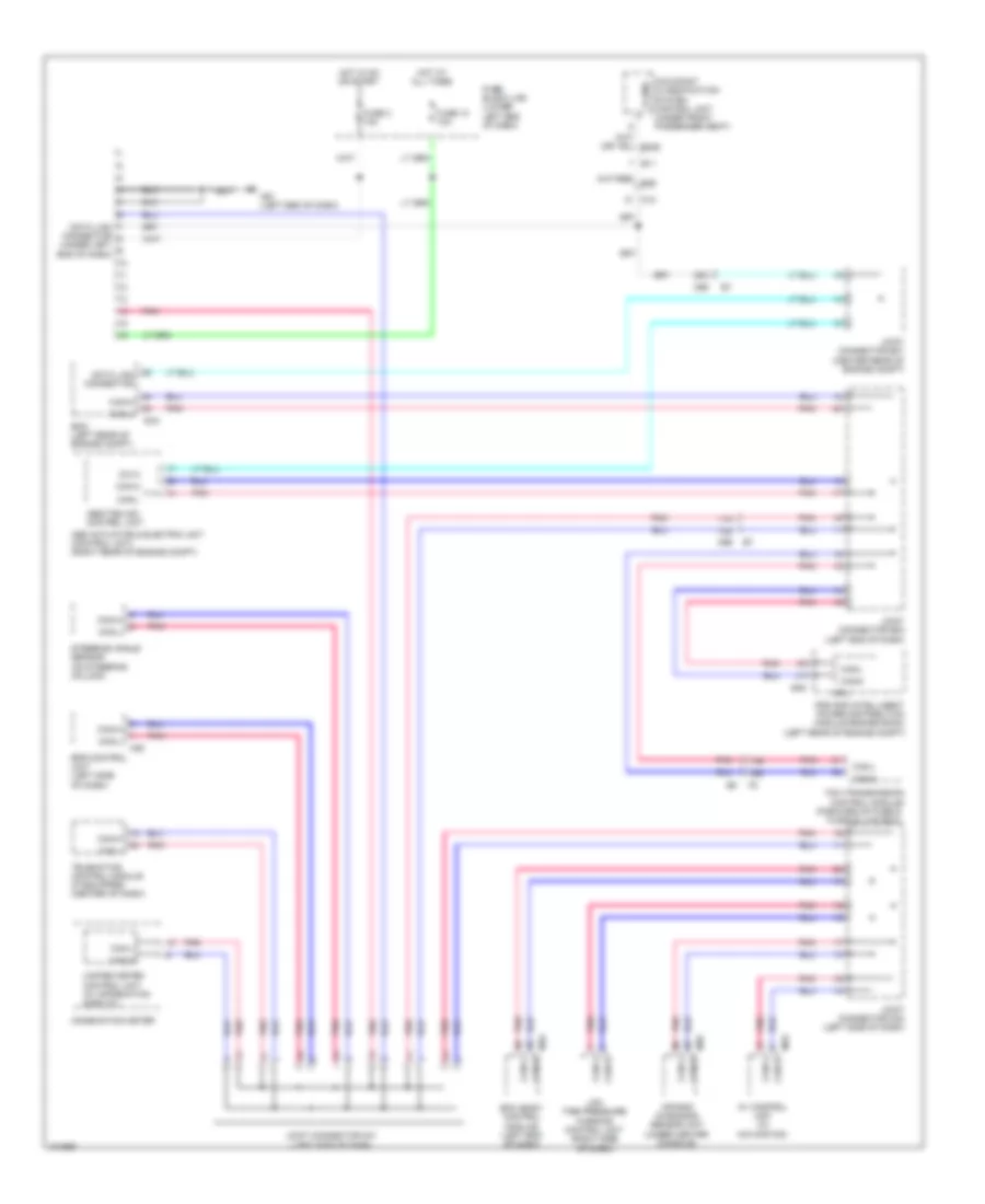
Computer Data Lines Wiring Diagram for Nissan NV200 S 2013
List of elements for Computer Data Lines Wiring Diagram for Nissan NV200 S 2013:
- (forward of fuse & fusible link box)
- 11a
- 12a
- 17b
- 18b
- 25a
- Abs actuator & electric unit (control unit) (right rear of engine compt)
- Abs/tcs/vdc control unit
- Air bag diagnosis sensor unit (under center console)
- Av control unit (w/ navigation)
- B11
- Bcm (body control module) (left end of dash)
- Can-h
- Can-l
- Combination meter
- Cpu
- Data link connector
- Data link connector (under left end of dash)
- Dia k
- E16
- E46
- Ecm (left rear of engine compt)
- Eps control unit (left side of dash)
- Fuse 10 10a
- Fuse 3 10a
- Fuse block (j/b) (lower left end of dash)
- Hot at all times
- Hot in on or start
- Ipdm e/r (intelligent power distribution module engine room) (left rear of engine compt)
- Joint connector e01 (center rear of engine compt)
- Joint connector e02 (left end of dash)
- Joint connector m01 (left side of dash)
- Joint connector m02 (left side of dash)
- K-line
- Low tire pressure warning control unit (right side of dash)
- M12
- M18
- M35
- M53
- M61 (left end of dash)
- M69
- M70
- Occupant classification system control unit (under front passenger seat)
- Pnk
- Steering angle sensor (on steering column)
- Tcm (transmission control module)
- Telematics control module (if equipped) (center of dash)
- Unified meter control unit (w/ information display)
COOLING FAN
Cooling Fan Wiring Diagram for Nissan NV200 S 2013
List of elements for Cooling Fan Wiring Diagram for Nissan NV200 S 2013:
- (left rear of engine compt) ipdm e/r (intelligent power distribution module engine room)
- (or pnk)
- 26a
- Avcc2
- Can-h
- Can-l
- Computer data lines system
- Cooling fan motor 1 (behind left side of radiator)
- Cooling fan motor 2 (behind right side of radiator)
- Cooling fan relay 1
- Cooling fan relay 2
- Cooling fan relay 3
- Cooling fan relay 4 (in ipdm e/r (intelligent power power distribution module engine room))
- Cooling fan relay 5 (in ipdm e/r (intelligent power power distribution module engine room))
- Cpu
- E15 (right rear of engine compt)
- E16
- E24 (left rear of engine compt)
- E42
- E43
- E44
- E45
- E46
- E47
- E48
- E49
- Ecm (left rear of engine compt)
- Ecm relay
- Ecm relay (self shut-off)
- Eng cool temp sens
- Engine controls system
- Engine coolant temperature sensor (rear of cylinder head)
- F10
- F11
- Fuse & fusible link box (forward of battery)
- Fuse 10a
- Fuse 20a
- Fuse block (j/b) (lower left end of dash)
- Fusible link box (battery) (on battery positive (+) post)
- Fusible link d 60a
- Fusible link f 40a
- Fusible link g 40a
- Hot at all times
- Hot in on or start
- Ignition relay
- M69
- Motor fan-rly driver 1
- Motor fan-rly driver 2
- Pdpres
- Pnk
- Power gnd
- Power sply for ecm
- Red
- Refrigerant pressure sensor (bottom right side of condenser)
- Sensor ground
CRUISE CONTROL
Cruise Control Wiring Diagram (1 of 2) for Nissan NV200 S 2013
List of elements for Cruise Control Wiring Diagram (1 of 2) for Nissan NV200 S 2013:
- (left rear of engine compt) e24
- (or red)
- 27b
- 33b
- 38a
- 39a
- 50a
- 92a
- Accel/res switch
- Accelerator pedal position sensor (top of accelerator pedal assembly)
- Apps1
- Apps2
- Ascd brake switch
- Ascd steering sw
- Ascd steering switch (if equipped)
- Brake pedal position switch (w/ ascd) (top of brake pedal assembly)
- Can-h
- Can-l
- Cancel switch
- Coast/ set switch
- Computer data lines system
- E16
- E43
- Ecm (left rear of engine compt)
- Ecm gnd
- Electric throttle control actuator (on throttle body assembly)
- F10
- F11
- Fuse 10 10a
- Fuse 11 10a
- Fuse 15a
- Fuse 3 10a
- Fuse block (j/b) (lower left end of dash)
- Hot at all times
- Hot in on or start
- Hot w/ ignition relay energized
- Ign
- Ipdm e/r (intelligent power distribution module engine room) (left rear of engine compt)
- J/c e01 (center rear of engine compt)
- J/c f01 (left side of engine compt)
- M30
- M69
- M69 e7
- M88
- On/off (main) switch
- Pnk
- Red
- Sens gnd
- Sens pwr sply
- Sensor 1
- Sensor 2
- Shield
- Spiral cable (combination switch) (in steering column)
- Stop lamp switch (top of brake pedal assembly)
- Stp lmp sw
- Throttle control motor
- Throttle ctrl mtr (close)
- Throttle ctrl mtr (open)
- Throttle ctrl mtr pwr sply
- Throttle ctrl mtr rly
- Throttle position sensor
- Tps1
- Tps2
Cruise Control Wiring Diagram (2 of 2) for Nissan NV200 S 2013
List of elements for Cruise Control Wiring Diagram (2 of 2) for Nissan NV200 S 2013:
- Batt
- Can h
- Can l
- Can-h
- Can-l
- Combination meter
- Computer data lines system
- Cruise ind (w/ ascd)
- E41 (left rear of engine compt)
- E43
- Fuse & fusible link box (forward of battery)
- Fuse 23 10a
- Fuse 43 10a
- Fuse 52 15a
- Gnd
- Hot at all times
- Hot in on or start
- Hot w/ ecm relay energized
- Ign
- Ipdm e/r (intelligent power distribution module engine room) (left rear of engine compt)
- J/c f01 (left side of engine compt)
- M57 (right kick panel)
- Pnk
- Pri spd sens
- Primary speed sensor (in transmission)
- Red
- Sec spd sens
- Secondary speed sensor (in transaxle)
- Sens gnd
- Tcm (transmission control module) (forward of fuse & fusible link box)
- Throttle control motor relay
- Unified meter control unit (w/ information display)
DEFOGGERS
Defoggers Wiring Diagram for Nissan NV200 S 2013
List of elements for Defoggers Wiring Diagram for Nissan NV200 S 2013:
- +ig
- B28
- B59
- Bat (f/l)
- Batt (fuse)
- Bcm (body control module) (left end of dash)
- Can-h
- Can-l
- Computer data lines system
- Cpu
- D115
- D501
- D503
- D505 (center of left back door)
- D525
- D527
- D531
- Door mirror defogger
- E24 (left rear of engine compt)
- E46
- E47
- E48
- Front air control
- Fuse & fusible link box (forward of battery)
- Fuse 10a
- Fuse 20a
- Fuse block (j/b) (lower left end of dash)
- Fusible link j 40a
- Gnd
- Gnd (sig)
- Hot at all times
- Hot in on or start
- Ignition relay
- Ipdm e/r (intelligent power distribution module engine room) (left rear of engine compt)
- Left door mirror
- M11
- M18
- M19
- M57 (right kick panel)
- M61 (left end of dash)
- M69 10a
- M69 91a
- M81
- Pnk
- Rear window defogger
- Rear window defogger indicator
- Rear window defogger relay
- Rear window defogger switch
- Red
- Right door mirror
- Rr def
- Rr def sw
- W/ cold areas
ELECTRONIC POWER STEERING
Electronic Power Steering Wiring Diagram for Nissan NV200 S 2013
List of elements for Electronic Power Steering Wiring Diagram for Nissan NV200 S 2013:
- Abs actuator & electric unit (right rear of engine compt)
- Bat
- Can-h
- Can-l
- Combination meter
- Computer data lines system
- E16
- Ecm (left rear of engine compt)
- Eps control unit (left side of dash)
- Eps motor
- Fuse & fusible link box (forward of battery)
- Fuse 10a
- Fuse block (j/b) (lower left end of dash)
- Fusible link m 60a
- Gnd
- Hot at all times
- Hot in on or start
- Ign
- M53
- M54
- M57 (right kick panel)
- M60
- M78 e11
- M95
- M96 (left end of dash)
- Motor (+)
- Motor (-)
- Nca
- Pnk
- Ps ind
- Red
- Torque sensor
- Tse (gnd)
- Tsm
- Tss
- Tsv
- Unified meter control unit (w/ information display)
ENGINE PERFORMANCE
2.0L
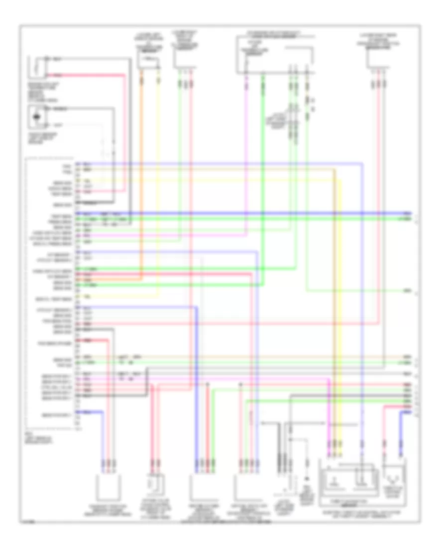
2.0L, Engine Performance Wiring Diagram (1 of 5) for Nissan NV200 S 2013
List of elements for 2.0L, Engine Performance Wiring Diagram (1 of 5) for Nissan NV200 S 2013:
- (lower left side of engine) oil temperature sensor
- (lower right front of engine) oil pressure sensor
- (lower right rear of engine) crankshaft position sensor (pos)
- (on engine air intake duct) mass air flow sensor
- 12b
- 13b
- 14b
- 30b
- 36b
- A/f sensor 1
- Air fuel ratio (a/f) sensor 1 (on exhaust manifold,
- Camshaft position sensor (phase) (rear of cylinder head)
- Ctrl sol valve
- E24 (left rear of engine compt)
- Ecm (left rear of engine compt)
- Electric throttle control actuator (on throttle body assembly)
- Eng oil press sens
- Eng oil temp sens
- Engine coolant temperature sensor (rear of cylinder head)
- F11
- Heated oxygen sensor 2 (in exhaust, downstream of catalytic converter)
- Htd oxy sensor 2
- Intake air temp sens
- Intake air temperature sensor
- Intake valve timing control solenoid valve (front of cylinder head)
- J/c f01 (left side of engine compt)
- Knock sens
- Knock sensor (left side of engine)
- Mass air flow sens
- Pnk
- Pnp sig
- Pos sens (phase)
- Pos sens (pos)
- Press sens
- Red
- Sens gnd
- Sens pwr sply
- Shield
- Temp sens
- Throttle control motor
- Throttle position sensor
- Tps1
- Tps2
- Upstream of catalytic converter)
2.0L, Engine Performance Wiring Diagram (2 of 5) for Nissan NV200 S 2013
List of elements for 2.0L, Engine Performance Wiring Diagram (2 of 5) for Nissan NV200 S 2013:
- (forward of fuel tank) evap canister vent control valve
- (left side of engine) condenser
- (top left of transmission) transmission range switch
- (top of fuel tank) fuel level sensor unit & fuel pump
- 16a
- 28b
- 29b
- 35a
- 36a
- 37a
- B19 (base of right "b" pillar)
- B23 m15
- B28 m11
- B29
- B29 m12
- E8 f8
- Evap control system pressure sensor (on evap canister assembly)
- F24
- Fuel level sensor
- Fuel pump
- Fuel tank temperature sensor
- Ignition coil 1 (w/ power transistor) (top of cylinder head)
- Ignition coil 2 (w/ power transistor) (top of cylinder head)
- Ignition coil 3 (w/ power transistor) (top of cylinder head)
- Ignition coil 4 (w/ power transistor) (top of cylinder head)
- Instrument cluster system
- J/c f01 (left side of engine compt)
- Loop wire
- M12
- M69
- Nca
- Pnk
- Red
- Spark plug
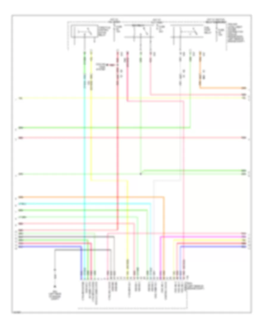
2.0L, Engine Performance Wiring Diagram (3 of 5) for Nissan NV200 S 2013
List of elements for 2.0L, Engine Performance Wiring Diagram (3 of 5) for Nissan NV200 S 2013:
- (or red)
- 24b
- 26a
- 27b
- 33b
- 34b
- A/f sens 1 htr
- Compt)
- Control valve
- Cooling fans system
- Ctrl mtr (close)
- Ctrl mtr (open)
- Ctrl mtr rly
- Ctrl sol valve
- E24 (left rear of engine
- E43
- E45
- E46
- E47
- Ecm (left rear of engine compt)
- Ecm gnd
- Ecm relay
- Ecm rly
- F10
- Fuel inj 1
- Fuel inj 2
- Fuel inj 3
- Fuel inj 4
- Fuel pump relay
- Fuel pump rly
- Fuse 15a
- Fuse 20a
- Hot at all times
- Hot w/ ignition relay energized
- Htd oxy sens 2 htr
- Ign sig 1
- Ign sig 2
- Ign sig 3
- Ign sig 4
- Ipdm e/r (intelligent power distribution module engine room) (left rear of engine compt)
- M69
- Pnk
- Pwr sply
- Red
- Throttle control motor relay
2.0L, Engine Performance Wiring Diagram (4 of 5) for Nissan NV200 S 2013
List of elements for 2.0L, Engine Performance Wiring Diagram (4 of 5) for Nissan NV200 S 2013:
- (top right rear of engine) evap canister purge volume control solenoid valve
- 21b
- Combination meter
- Computer data lines system
- E43
- E45
- Fuel injector (top left side of cylinder head)
- Fuse 10a
- Fuse 15a
- Fuse block (j/b) (lower left side of engine)
- Hot at all times
- Hot in on or start
- Hot w/ ignition relay energized
- Ipdm e/r (intelligent power distribution module engine room) (left rear of engine compt)
- M57 (right kick panel)
- Malfunction ind lamp (mil)
- Pnk
- Red
- Unified meter control unit (w/ information display)
2.0L, Engine Performance Wiring Diagram (5 of 5) for Nissan NV200 S 2013
List of elements for 2.0L, Engine Performance Wiring Diagram (5 of 5) for Nissan NV200 S 2013:
- (center rear of engine compt) j/c e01
- (top of brake pedal assembly) stop lamp switch
- 92a
- Acc pedal poss sens 2
- Accelerator pedal position sensor (top of accelerator pedal assembly)
- Ascd brake sw
- Ascd sw
- Can-h
- Can-l
- Computer data lines system
- Cruise control system
- Data link conn
- E16
- E41 (left rear of engine compt)
- Ecm (left rear of engine compt)
- Fuse 10a
- Fuse block (j/b) (lower left side of engine)
- Gnd
- Hot at all times
- Ign sw
- M69
- Pnk
- Poss sens 1
- Press sens
- Pwr sply
- Red
- Refrigerant pressure sensor (bottom right side of condenser)
- Sens gnd
- Sens pwr sply
- Sensor 1
- Sensor 2
- Stop lamp sw
EXTERIOR LIGHTS
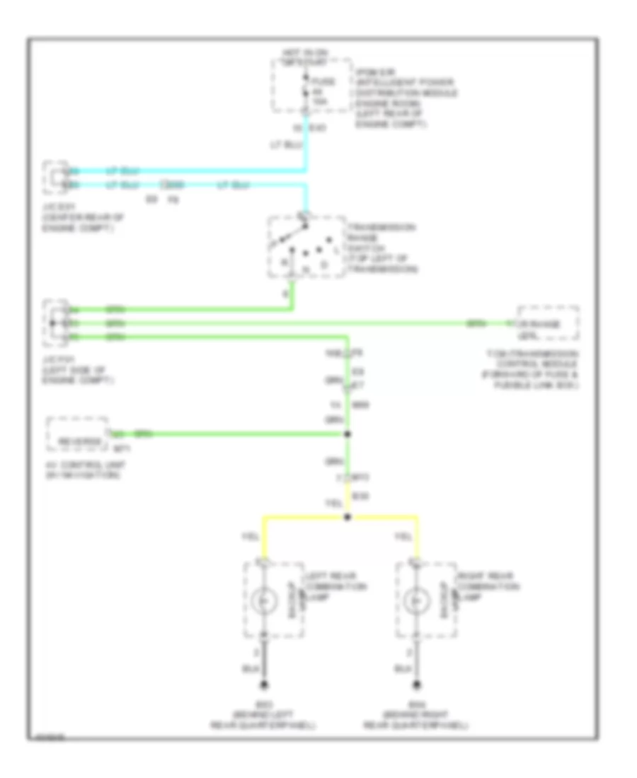
Backup Lamps Wiring Diagram for Nissan NV200 S 2013
List of elements for Backup Lamps Wiring Diagram for Nissan NV200 S 2013:
- 16b
- 20b
- Av control unit (w/ navigation)
- B30
- B63 (behind left rear quarterpanel)
- B64 (behind right rear quarterpanel)
- E43
- Fuse 10a
- Hot in on or start
- Ipdm e/r (intelligent power distribution module engine room) (left rear of engine compt)
- J/c e01 (center rear of engine compt)
- J/c f01 (left side of engine compt)
- Left rear combination lamp lamp backup
- M13
- M69
- M71
- R range sw
- Reverse
- Right rear combination lamp lamp backup
- Tcm (transmission control module (forward of fuse & fusible link box)
- Transmission range switch (top left of transmission)
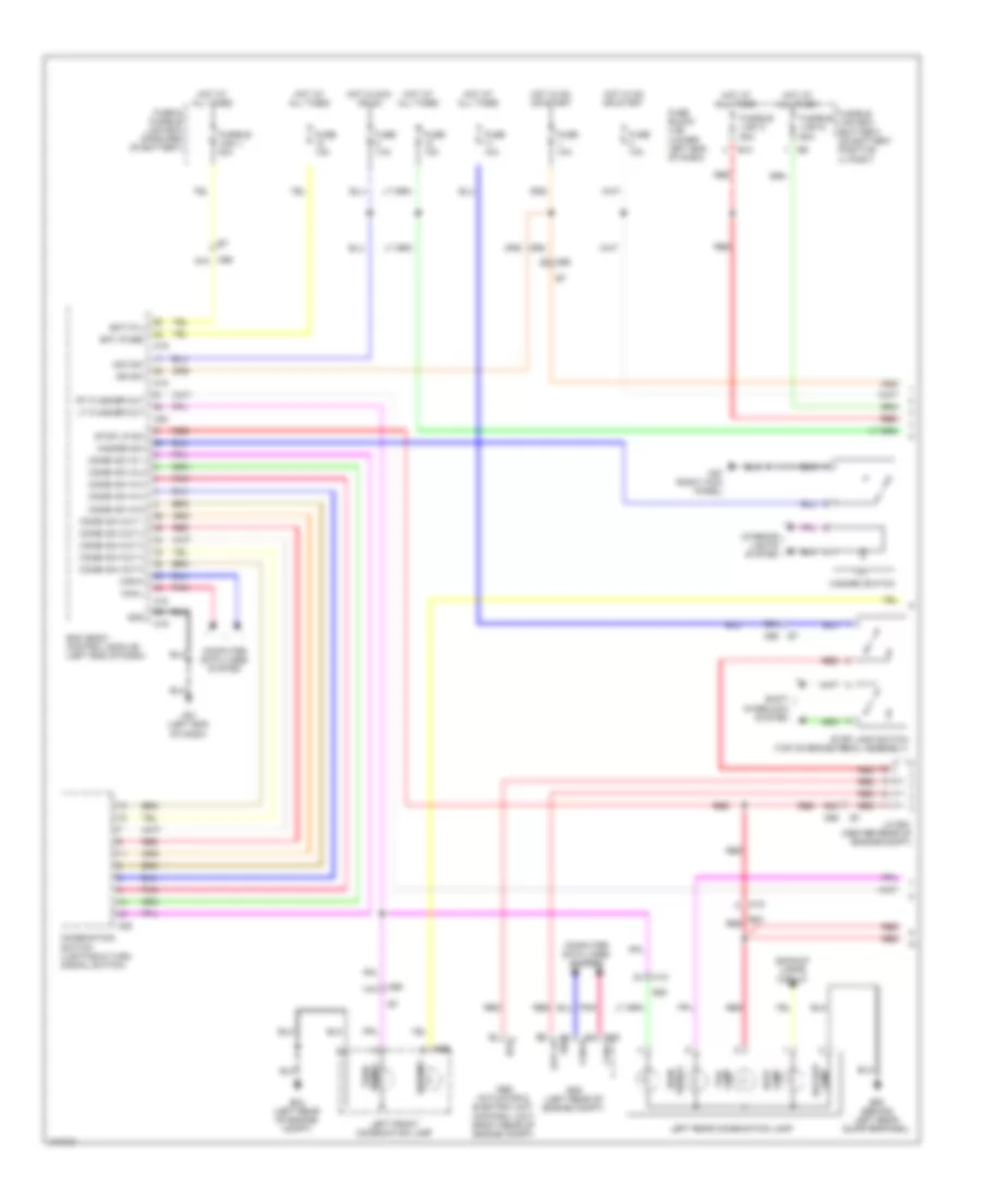
Exterior Lamps Wiring Diagram (1 of 2) for Nissan NV200 S 2013
List of elements for Exterior Lamps Wiring Diagram (1 of 2) for Nissan NV200 S 2013:
- 14a
- 92a
- 93a
- Abs actuator & electric unit (control unit) (right rear of engine compt)
- Acc sw
- B23
- B30
- B63 (behind left rear quarterpanel)
- Backup lamp
- Backup lamps circuit
- Bat (f/l)
- Bat (fuse)
- Bcm (body control module) (left end of dash)
- Bls
- Can-h
- Can-l
- Combi sw in 1
- Combi sw in 2
- Combi sw in 3
- Combi sw in 4
- Combi sw in 5
- Combi sw out 1
- Combi sw out 2
- Combi sw out 3
- Combi sw out 4
- Combi sw out 5
- Combination switch (lighting & turn signal switch)
- Computer data lines system
- E10
- E16
- E24 (left rear of engine compt)
- E66
- Ecm (left rear of engine compt)
- Fuse & fusible link box (forward of battery)
- Fuse 10a
- Fuse block (j/b) (lower left end of dash)
- Fusible link box (battery) (on battery positive (+) post)
- Fusible link c 80a
- Fusible link d 60a
- Fusible link j 40a
- Gnd
- Hazard sw
- Hazard switch
- Hot at all times
- Hot in acc or on
- Hot in on or start
- Ign sw
- Ill
- Interior lights system
- J/c e01 (center rear of engine compt)
- Lamp stop
- Left front combination lamp
- Left rear combination lamp
- Lt flasher out
- M13
- M15
- M18
- M19
- M20
- M28
- M57 (right kick panel)
- M61 (left end of dash)
- M69
- M69 91a
- Parking
- Pnk
- Red
- Rt flasher out
- Shift interlock system
- Signal turn
- Stop lamp switch (top of brake pedal assembly)
- Stop lp sw
- Stp lp
- Tail lamp
- Turn signal
Exterior Lamps Wiring Diagram (2 of 2) for Nissan NV200 S 2013
List of elements for Exterior Lamps Wiring Diagram (2 of 2) for Nissan NV200 S 2013:
- 15a
- 8a m69
- B30
- B58
- B64 (behind right rear quarterpanel)
- Backup lamps circuit
- Bat
- Buzzer
- Can-h
- Can-l
- Combination meter
- Computer data lines system
- Cpu
- D500
- D502
- D504
- D505 (center of left back door)
- D552
- D575
- E15 (right rear of engine compt)
- E24 (left rear of engine compt)
- E42
- E45
- E46
- E47
- E48
- E67
- Fuse 10a
- Gnd (circuit)
- Gnd (ill)
- Gnd (pwr)
- Gnd (sig)
- High mounted stop lamp
- Ign
- Ignition relay
- Ind left turn
- Ind right turn
- Ipdm e/r (intelligent power distribution module engine room) (left rear of engine compt)
- J/c m03 (left side of dash)
- Lamp backup
- Lamp tail
- Left license plate lamp
- M13
- M57 (right kick panel)
- M69
- Parking
- Pnk
- Red
- Right front combination lamp
- Right license plate lamp
- Right rear combination lamp
- Signal turn
- Stop lamp
- Tail lamp relay
- Turn signal
- Unified meter control unit (w/ information display)
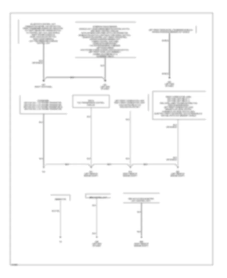
GROUND DISTRIBUTION
Ground Distribution Wiring Diagram (1 of 2) for Nissan NV200 S 2013
List of elements for Ground Distribution Wiring Diagram (1 of 2) for Nissan NV200 S 2013:
- Abs actuator & electric unit (control unit)
- Condenser, ignition coil 1 (w/ power transistor), ignition coil 2 (w/ power transistor), ignition coil 3 (w/ power transistor) & ignition coil 4 (w/ power transistor)
- E15 (right rear of engine compt)
- E24 (left rear of engine compt)
- E41 (left rear of engine compt)
- E69 (right rear of engine compt)
- Ecm & tcm (transmission control module)
- Eps control unit
- F24
- Front wiper motor, horn, daytime light relay 1, daytime light relay 2, ipdm (intelligent power distribution module engine room), left front combination lamp, brake fluid level switch, washer fluid level switch, ecm, electric throttle control actuator shield & air fuel ratio (a/f) sensor 1 shield
- Generator
- Left front combination lamp, right front combination lamp, cooling fan relay 5 & cooling fan motor 1
- Left front door satellite sensor shield & air bag diagnosis sensor unit shield
- M57 (right kick panel)
- M61 (left end of dash)
- M93 (left end of dash)
- M96 (left end of dash)
- Shield
- Steering angle sensor, dongle unit, door mirror remote control switch, bcm (body control module), nats antenna amplifier, data link connector, combination switch (lighting & turn signal switch), telematics control unit, front air control, air bag diagnosis sensor unit, thermo control amplifier, console power socket, yaw rate/side/decel g sensor, left door mirror, main power window & door lock/unlock switch, left front door lock assembly, camera, blower relay & accessory relay
Ground Distribution Wiring Diagram (2 of 2) for Nissan NV200 S 2013
List of elements for Ground Distribution Wiring Diagram (2 of 2) for Nissan NV200 S 2013:
- Air bag diagnosis sensor unit (shield wire) & crash zone sensor shield
- Air bag diagnosis sensor unit, left side curtain air bag module shield & left front side air bag satellite sensor shield
- Air bag diagnosis sensor unit, right side curtain air bag module shield & right front side air bag satellite sensor shield
- B19 (base of right "b" pillar)
- B63 (behind left rear quarterpanel)
- B64 (behind right rear quarterpanel)
- B66 (base of left "b" pillar)
- B67 (middle of right "b" pillar)
- Back door switch, rear window defogger, high mounted stop lamp, left license plate lamp & right license plate lamp
- D505 (center of left back door)
- E70 (left side of engine compt)
- Fuel level sensor unit & fuel pump & occupant classification system control unit
- M94 (right side of dash)
- Rear power socket, left seat belt buckle switch, map lamp assembly, right seat belt buckle switch & left rear combination lamp
- Right front door satellite sensor shield & air bag diagnosis sensor unit shield
- Right rear combination lamp
- Shield
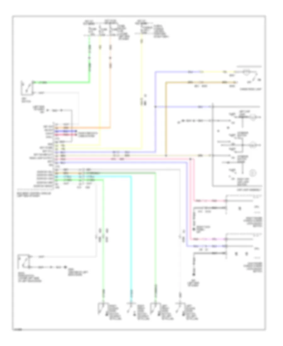
HEADLIGHTS
Headlights Wiring Diagram (1 of 2) for Nissan NV200 S 2013
List of elements for Headlights Wiring Diagram (1 of 2) for Nissan NV200 S 2013:
- (left end of dash)
- 91a
- Acc sw
- Bat (f/l)
- Bat (fuse)
- Bcm (left end of dash)
- Can-h
- Can-l
- Combination switch (lighting & turn signal switch)
- Computer data lines system
- Fuse & fusible link box (forward of battery)
- Fuse 10a
- Fuse block (j/b) (lower left end of dash)
- Fusible link j 40a
- Gnd
- Hot at all times
- Hot in on or acc
- Hot in on or start
- Ign sw
- Input 1
- Input 2
- Input 3
- Input 4
- Input 5
- M18
- M19
- M28
- M61
- M69
- M69 26a
- Output 1
- Output 2
- Output 3
- Output 4
- Output 5
- Pnk
- Red
Headlights Wiring Diagram (2 of 2) for Nissan NV200 S 2013
List of elements for Headlights Wiring Diagram (2 of 2) for Nissan NV200 S 2013:
- (left rear of engine compt) e24
- +ig
- Brake ind
- Can-h
- Can-l
- Canada
- Combination meter
- Computer data lines system
- Cpu
- Daytime light relay 1 (in ipdm e/r (intelligent power distribution module engine room))
- Daytime light relay 2 (in ipdm e/r (intelligent power distribution module engine room))
- E10
- E15 (right rear of engine compt)
- E24 (right rear of engine compt)
- E25
- E26
- E42
- E43
- E46
- E47
- E48
- Engine compt) e24
- Fuse 10a
- Fuse 15a
- Fusible link 80a
- Fusible link box (battery) (on battery positive (+) post)
- H/lp hi
- H/lp lo
- Headlamp high relay
- Headlamp low relay
- High beam
- High beam ind
- Hot at all times
- Ignition relay
- Ipdm e/r (intelligent power distribution module engine room) (left rear of engine compt)
- Left front combination lamp
- Low beam
- M57 (right kick panel)
- Parking brake switch (base parking brake lever assembly)
- Pnk
- Pwr (gnd)
- Red
- Right front combination lamp
- Rly cont drl
- Sig (gnd)
- Unified meter control unit (w/ information display)
- Usa
HORN
Horn Wiring Diagram for Nissan NV200 S 2013
List of elements for Horn Wiring Diagram for Nissan NV200 S 2013:
- 7a m69
- Combination switch (spiral cable) (in steering column)
- Cpu
- E18
- E20
- E24 (left rear of engine compt)
- E46
- Fuse & fusible link block (forward of battery)
- Fuse 10a
- Horn (left front of engine compt)
- Horn relay (in fuse & fusible link box)
- Horn rly ctrl
- Horn switch
- Hot at all times
- Ipdm e/r (intelligent power distribution module engine room) (left rear of engine compt)
- M30
- M88
- Red
- W/ remote keyless entry system
INSTRUMENT CLUSTER
Instrument Cluster Wiring Diagram for Nissan NV200 S 2013
List of elements for Instrument Cluster Wiring Diagram for Nissan NV200 S 2013:
- (w/ information display) unified meter control unit
- 31a
- 32a
- 34a
- Abs ind
- Air bag ind
- Ambient sensor (right rear of engine compt)
- B225
- B250
- B29
- B30
- B58
- B65
- Back door switch (lower left side of left back door)
- Bcm (body control module) (left end of dash)
- Belt ind
- Brake fluid level switch (on brake fluid reservoir)
- Brake ind
- Buzzer
- Can-h
- Can-l
- Charge ind
- Combination meter
- Computer data lines system
- Cpu
- Cruise ind (w/ ascd)
- D500
- D505 (center of left back door)
- Door ind
- Door sw (as)
- Door sw (back)
- Door sw (dr)
- Door sw (rl)
- Door sw (rr)
- E16
- E24 (left rear of engine compt)
- E46
- Ecm (left rear of engine compt)
- F11
- Fuel level sensor unit & fuel pump (fuel level sensor) (top of fuel tank)
- Fuse 10a
- Fuse block (j/b) (lower left end of dash)
- High beam ind
- Hot at all times
- Hot in on or start
- Interior lights system
- Ipdm e/r (intelligent power distribution module engine room) (left rear of engine compt)
- J/c e01 (center rear of engine compt)
- Left front door switch (on left front "b" pillar)
- Left sliding door switch (on left "b" pillar)
- Left turn ind
- M12
- M13
- M18
- M20
- M57 (right kick panel)
- M69
- Malfunction ind lamp (mil)
- O/d off ind
- Oil press avcc1
- Oil press sens
- Oil pressure ind
- Oil pressure sensor (lower right front of engine)
- Parking brake switch (base of parking brake lever assembly)
- Pnk
- Ps ind
- Red
- Right front door switch (on right front "b" pillar)
- Right sliding door switch (on right "b" pillar)
- Right turn ind
- Security ind
- Security ind out
- Sens gnd
- Slip ind
- Sound & navigation systems
- Speedometer
- Starting/charging system
- Tachometer
- Temperature ind
- Tire pressure ind
- Transmissions system
- Vdc off ind
- Washer ind
- Wiper/washer system
INTERIOR LIGHTS
Courtesy Lamps Wiring Diagram for Nissan NV200 S 2013
List of elements for Courtesy Lamps Wiring Diagram for Nissan NV200 S 2013:
- (left end of dash) m61
- (right kick panel) m57
- 91a
- B225
- B250
- B30
- B32
- B400
- B401
- B402
- B58
- B65
- Back door switch (lower left side of left back door)
- Bat
- Bat (f/l)
- Bat (fuse)
- Bat saver out
- Bcm (body control module) (left end of dash)
- Can-h
- Can-l
- Cargo room lamp
- Computer data lines system
- Cpu
- D102
- D500
- D505 (center of left back door)
- Door sw (as)
- Door sw (back)
- Door sw (dr)
- Door sw (rl)
- Door sw (rr)
- Fuse & fusible link box (forward of battery)
- Fuse 10a
- Fuse block (j/b) (lower left end of dash)
- Fusible link j 40a
- Gnd
- Hot at all times
- Hot in on or start
- Ign
- Ign sw
- Interior switch (all)
- Interior switch (door)
- Key sw
- Key switch
- Left front door switch (on left "b" pillar)
- Left map lamp switch
- Left sliding door switch (on left "b" pillar)
- M12
- M13
- M18
- M19
- M20
- M29
- M61 (left end of dash)
- M69
- M74
- Main power window & door lock/unlock switch
- Map lamp assembly
- Off
- Pnk
- Right front door switch (on right "b" pillar)
- Right off map lamp switch
- Right power window & door lock/unlock switch
- Right sliding door switch (on right "b" pillar)
- Room lamp output
Instrument Illumination Wiring Diagram (1 of 2) for Nissan NV200 S 2013
List of elements for Instrument Illumination Wiring Diagram (1 of 2) for Nissan NV200 S 2013:
- 91a
- Bat
- Bat (f/l)
- Bat (fuse)
- Bcm (body control module) (left end of dash)
- Can-h
- Can-l
- Combination meter
- Combination switch (lighting & turn signal switch)
- Computer data lines system
- Fuse & fusible link box (forward of battery)
- Fuse 10a
- Fuse block (j/b) (lower left end of dash)
- Fusible link j 40a
- Gnd
- Gnd (ill)
- Hazard switch
- Hot at all times
- Hot in on or start
- Ign
- Ign sw
- Illu ctrl output
- Input 1
- Input 2
- Input 3
- Input 4
- Input 5
- M18
- M19
- M28
- M57 (right kick panel)
- M61 (left end of dash)
- M69
- Output 1
- Output 2
- Output 3
- Output 4
- Output 5
- Pnk
- Red
- Unified meter control unit (w/ information display)
Instrument Illumination Wiring Diagram (2 of 2) for Nissan NV200 S 2013
List of elements for Instrument Illumination Wiring Diagram (2 of 2) for Nissan NV200 S 2013:
- (if equipped) ascd steering switch
- (if equipped) steering wheel audio control switch
- +ig
- Audio unit
- Av control unit
- Can-h
- Can-l
- Combination switch (spiral cable) (in steering column)
- Computer data lines system
- Cpu
- Cvt shift selector
- E10
- E24 (left rear of engine compt)
- E42
- E45
- E46
- E47
- E48
- Front air control
- Fuse & fusible link box (battery) (on battery positive (+) post)
- Fuse 10a
- Fusible link c 80a
- Gnd (power)
- Gnd (signal)
- Hot at all times
- Ignition relay
- Ill (+)
- Ill (-)
- Ipdm e/r (intelligent power distribution module engine room) (left rear of engine compt)
- Joint connector m03 (left side of dash)
- M30
- M31
- M43
- M69
- M69 26a
- M70
- M71
- M88
- Pnk
- Red
- Tail lamp relay
- Tail/l rly
- Vdc off switch
- W/ navigation
- W/o navigation
NAVIGATION
Navigation Wiring Diagram for Nissan NV200 S 2013
List of elements for Navigation Wiring Diagram for Nissan NV200 S 2013:
- (right kick panel) m57
- 16b
- 20b
- Acc
- Ant on
- Antenna amp
- Antenna satellite
- Aux gnd
- Aux jack
- Aux l
- Aux r
- Av control unit
- B30
- Base antenna
- Bat
- Bcm (body control module) (left end of dash)
- Camera (+)
- Camera (-) shield
- Camera gnd
- Camera on
- Can-h
- Can-l
- Combination meter
- Computer data lines system
- D115 m81
- D500 b58
- E43
- E8 f8
- Fr sp lh (+)
- Fr sp lh (-)
- Fr sp rh (+)
- Fr sp rh (-)
- Fuse & fusible link box (forward of battery)
- Fuse 10a
- Fuse 15a
- Fuse 5 10a
- Fuse block (j/b) (lower left end of dash)
- Gnd
- Gps ant
- Gps antenna
- Gps shield
- Hot at all times
- Hot in on or acc
- Hot in on or start
- Ign
- Ill (-)
- Ill(+)
- Interior lights system
- Ipdm e/r (intelligent power distribution module engine room) (left rear of engine compt)
- J/c e01 (center rear of engine compt)
- J/c f01 (left side of engine compt)
- J/c m02 (left side of dash)
- Left front door speaker
- M13
- M25 m200
- M30
- M501
- M502
- M68
- M69 e7
- M70
- M71
- M73
- M82 m500
- M83 m503
- M84
- M85
- M88
- Main ant
- Mic gnd
- Mic signal
- Mic vcc
- Microphone (top left side of dash)
- Mr output
- Nca
- Phone/ end
- Phone/ send
- Pnk
- R p
- Rear view camera (center of left back door)
- Red
- Reverse
- Right front door
- Sat ant
- Sat shield
- Seek down
- Seek up
- Shield
- Source
- Speaker
- Speed signal
- Spiral cable (in steering column)
- Steering wheel audio control switches
- Strg sw a
- Strg sw b
- Strg sw gnd
- Tan
- Transmission range switch (top left of transmission)
- Unified meter control unit (w/ information control display)
- Usb d (+)
- Usb d (-)
- Usb gnd
- Usb interface
- Usb shield
- Usb vcc
- Volume down
- Volume up
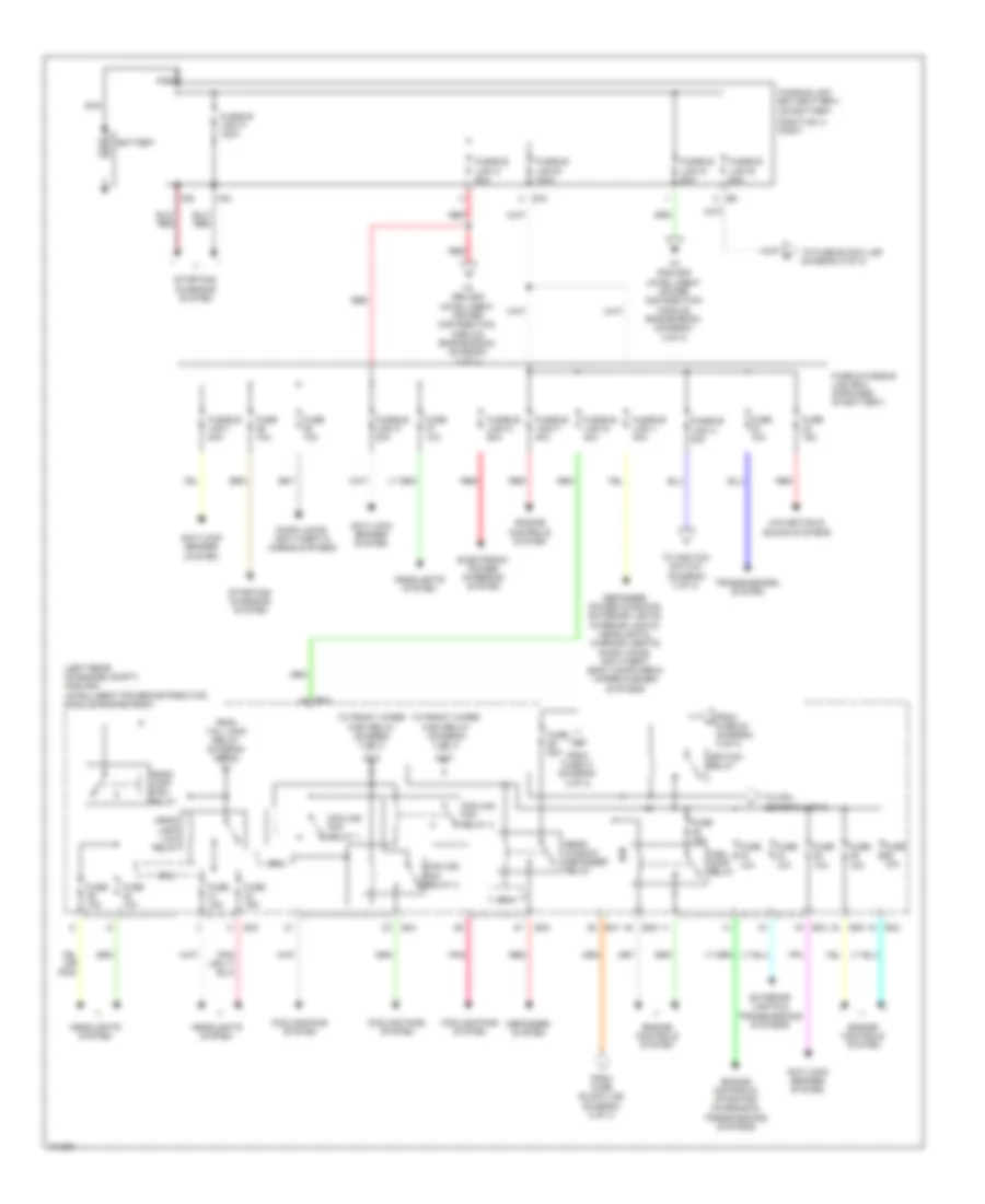
POWER DISTRIBUTION
Power Distribution Wiring Diagram (1 of 3) for Nissan NV200 S 2013
List of elements for Power Distribution Wiring Diagram (1 of 3) for Nissan NV200 S 2013:
- (left rear of engine compt) ipdm e/r (intelligent power distribution module engine room)
- (on battery
- Anti-lock brakes system
- Battery
- Cooling fan relay 1
- Cooling fan relay 2
- Cooling fan relay 3
- Cooling fans system
- Cpu
- Defogger system
- Defogger, power windows, exterior lights, interior lights, headlights, warning, seats, door locks, anti-theft, body computer & wiper/washer systems
- Door locks, anti-theft & horns systems
- E10
- E43
- E44
- E45
- E46
- E47
- E48
- Electronic power steering system
- Engine controls system
- Engine controls, starting/ charging & transmissions systems
- Exterior lights & transmissions systems
- F39
- F40
- From fuse 31 (diagram 3 of 3)
- From fuse 52 (diagram 3 of 3)
- From fuse block (j/b) (diagram 2 of 3)
- From tail lamp relay (diagram 3 of 3)
- Fuel pump relay
- Fuse & fusible link box (forward of battery)
- Fuse 10a
- Fuse 15a
- Fuse 20a
- Fusible link a 120a
- Fusible link b 100a
- Fusible link box (battery)
- Fusible link c 80a
- Fusible link d 60a
- Fusible link e 80a
- Fusible link f 40a
- Fusible link g 40a
- Fusible link h 40a
- Fusible link i 40a
- Fusible link j 40a
- Fusible link k 30a
- Fusible link m 60a
- Head- lamp high relay
- Head- lamp low relay
- Headlights system
- Ignition relay
- Navigation & sound systems
- Nca
- Pnk
- Positive (+) post)
- Rear window defogger relay
- Red
- Starting/ charging system
- To cpu (diagram 3 of 3)
- To front wiper high relay (diagram 3 of 3)
- To fuse block (j/b) (diagram 2 of 3)
- To ignition switch (diagram 2 of 3)
- To ipdm e/r (intelligent power distribution module engine room) (diagram 3 of 3)
- Transmissions system
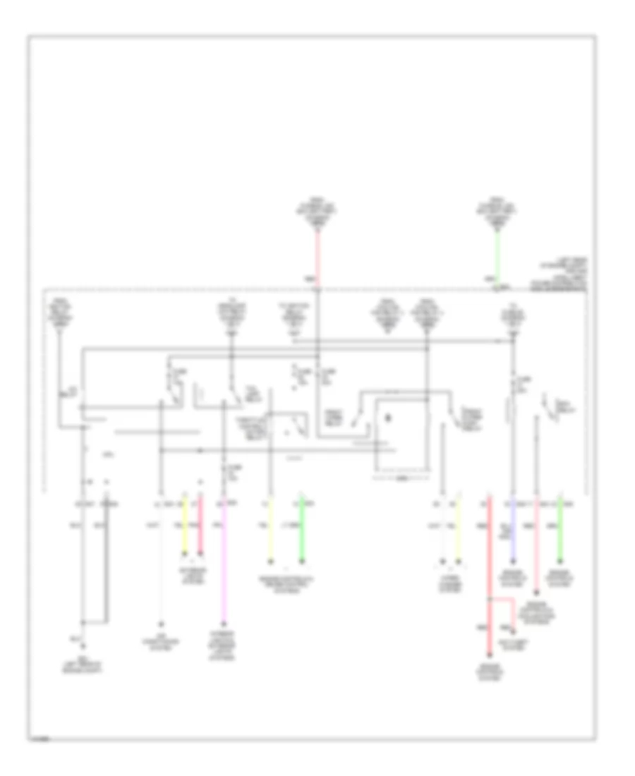
Power Distribution Wiring Diagram (2 of 3) for Nissan NV200 S 2013
List of elements for Power Distribution Wiring Diagram (2 of 3) for Nissan NV200 S 2013:
- 96a
- Acc
- Accessory relay
- Air conditioning system
- B23
- Blower relay
- Body computer, engine controls, exterior lights, anti-lock brakes & transmissions systems
- Console power socket
- Door locks, headlights, exterior lights, anti-theft, warning, interior lights & body computer systems
- E11
- E152
- Exterior lights,
- From fuse & fusible link box (diagram 1 of 3)
- From fusible link box (battery) (diagram 1 of 3)
- Fuse 10a
- Fuse 15a
- Fuse 20a
- Fuse block (j/b) (lower left end of dash)
- Ig1
- Ig2
- Ignition switch
- Interior lights, body computer, headlights, power windows, defogger, warning, door locks & anti-theft systems
- M15
- M31
- M61 (left end of dash)
- M69 26a
- M78
- Mirrors, warning, door locks, exterior lights, headlights, anti-theft, navigation, sound & body computer systems
- Off
- Rear power socket
- Red
- Start
- Starting/ charging system
- To ipdm e/r (intelligent power distribution module engine room) (diagram 1 of 3)
- Wiper/ washer system
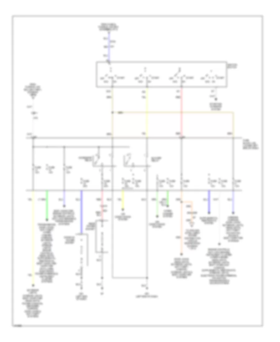
Power Distribution Wiring Diagram (3 of 3) for Nissan NV200 S 2013
List of elements for Power Distribution Wiring Diagram (3 of 3) for Nissan NV200 S 2013:
- (left rear of engine compt) ipdm e/r (intelligent power distribution module engine room)
- A/c relay
- Air conditioning system
- Anti-theft system
- Cpu
- E24 (left rear of engine compt)
- E42
- E43
- E45
- E47
- E48
- Ecm relay
- Engine controls & cooling fans systems
- Engine controls & cruise control systems
- Engine controls system
- Exterior lights system
- From cooling fan relay 3 (diagram 1 of 3)
- From fusible link box (battery) (diagram 1 of 3)
- From ignition relay (diagram 1 of 3)
- Front wiper high relay
- Front wiper relay
- Fuse 10a
- Fuse 15a
- Fuse 20a
- Fuse 30a
- Interior lights & exterior lights systems
- Pnk
- Red
- Tail lamp relay
- Throttle control motor relay
- To fuse 29 (diagram 1 of 3)
- To headlamp low relay (diagram 1 of 3)
- To ignition relay (diagram 1 of 3)
- Wiper/ washer system
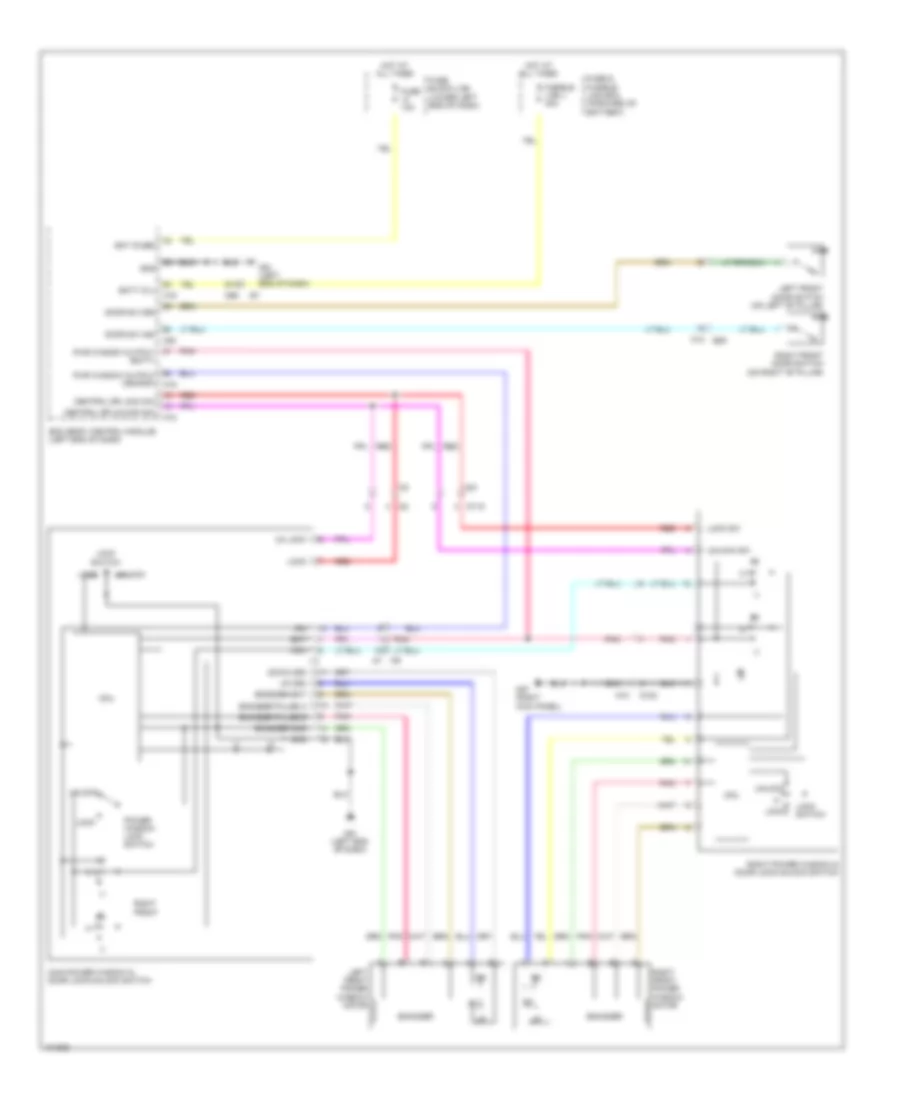
POWER DOOR LOCKS
Power Door Locks Wiring Diagram (1 of 2) for Nissan NV200 S 2013
List of elements for Power Door Locks Wiring Diagram (1 of 2) for Nissan NV200 S 2013:
- (left rear of engine compt) ipdm e/r (intelligent power distribution module engine room)
- +ig
- Acc sw
- B225
- B250
- B29
- B58
- B65
- Back door switch (lower left side of left back door)
- Bat (f/l)
- Bat (fuse)
- Batt saver output
- Bcm (body control module) (left end of dash)
- Can h
- Can l
- Can-h
- Can-l
- Combination meter
- Computer data lines system
- Cpu
- D500
- D505 (center of left back door)
- Door lock output
- Door lock sw
- Door sw (as)
- Door sw (back)
- Door sw (dr)
- Door sw (rl)
- Door sw (rr)
- Door unlck out (dr)
- Door unlock sw
- Dr unlck out (other)
- E24 (left rear of engine compt)
- E46
- E47
- E48
- Exterior lights system
- Fuse 10a
- Fuse block (j/b) (lower left end of dash)
- Gnd
- Gnd (pwr)
- Gnd (sig)
- H/lp hi
- H/lp lo
- Headlights system
- Horn rly cont
- Horns system
- Hot at all times
- Hot in on or acc
- Hot in on or start
- Ign sw
- Ignition relay
- Ind door
- Interior lights system
- Key cyl lock sw
- Key cyl unlock sw
- Key sw
- Key switch
- Left front door switch (on left "b" pillar)
- Left sliding door switch (on left "b" pillar)
- Lh flasher output
- M12
- M18
- M19
- M20
- M57 (right kick panel)
- M61 (left end of dash)
- Pnk
- Power sply
- Red
- Remote keyless entry receiver (right side of dash)
- Rh flasher output
- Right front door switch (on right "b" pillar)
- Right sliding door switch (on right "b" pillar)
- Room lamp output
- Security ind
- Security ind output
- Sens gnd
- Signal
- Unified meter control unit (w/ information display)
Power Door Locks Wiring Diagram (2 of 2) for Nissan NV200 S 2013
List of elements for Power Door Locks Wiring Diagram (2 of 2) for Nissan NV200 S 2013:
- (front of left sliding door) left sliding door lock actuator
- (front of right sliding door) right sliding door lock actuator
- 91a
- Actuator
- B23
- B59
- Back door lock actuator (center of left back door)
- Cpu
- D1 m9
- D102
- D115
- D501
- Door lock
- Door unlock
- E18
- E20
- E24 (left rear of engine compt)
- Fuse & fusible link box (forward of battery)
- Fuse 10a
- Fusible link j 40a
- Gnd
- Horn (left front of engine compt)
- Horn relay (in fuse & fusible link box)
- Hot at all times
- Key cylinder switch
- Left front door lock assembly
- Left sliding door contact switch (pillar) (on left "b" pillar)
- Lock
- M15
- M57 (right kick panel)
- M61 (left end of dash)
- M69
- M74
- M81
- Main power window & door lock/ unlock switch
- Pnk
- Red
- Right front door lock actuator
- Right power window & door lock/ unlock switch
- Right sliding door contact switch (pillar) (on right "b" pillar)
- Sliding door contact switch (door) (on left "b" pillar)
- Sliding door contact switch (door) (on right "b" pillar)
- Telematics control module (if equipped) (center of dash)
- Unlock
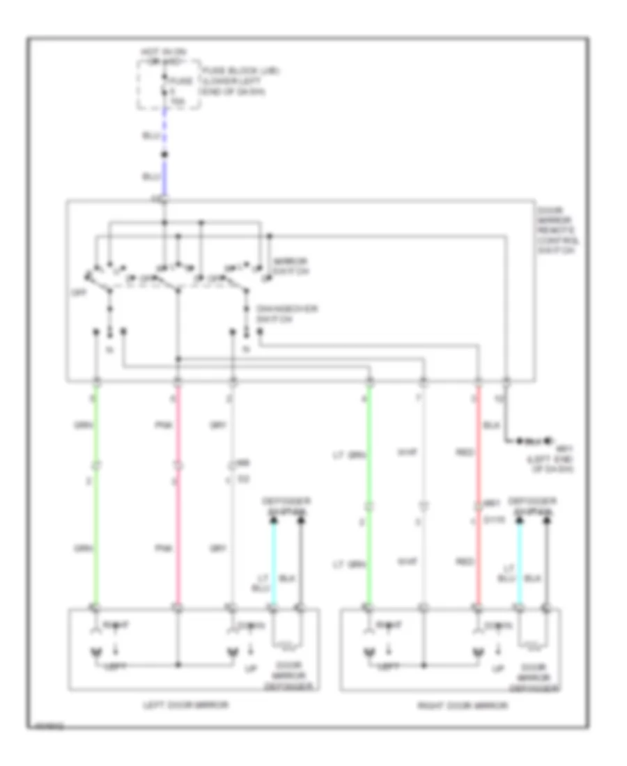
POWER MIRRORS
Power Mirrors Wiring Diagram for Nissan NV200 S 2013
List of elements for Power Mirrors Wiring Diagram for Nissan NV200 S 2013:
- Changeover switch
- D115
- Defogger system
- Door mirror defogger
- Door mirror remote control switch
- Down
- Fuse 10a
- Fuse block (j/b) (lower left end of dash)
- Hot in on or acc
- Left
- Left door mirror
- M61 (left end of dash)
- M81
- Mirror switch
- Off
- Pnk
- Red
- Right
- Right door mirror
POWER WINDOWS
Power Windows Wiring Diagram for Nissan NV200 S 2013
List of elements for Power Windows Wiring Diagram for Nissan NV200 S 2013:
- 91a
- Bat
- Bat (fuse)
- Batt (f/l)
- Bcm (body control module) (left end of dash)
- Central dr lock sw
- Central dr unlock sw
- Com
- Cpu
- D102
- D115
- Door sw (as)
- Door sw (dr)
- Down (dr)
- Encoder
- Encoder bat
- Encoder gnd
- Encoder pulse a
- Encoder pulse b
- Fuse & fusible link box (forward of battery)
- Fuse 10a
- Fuse block (j/b) (lower left end of dash)
- Fusible link j 40a
- Gnd
- Hot at all times
- Ign
- Left front door switch (on left "b" pillar)
- Left front power window motor
- Lock
- Lock sw
- Lock switch
- M12 b29
- M18
- M19
- M20
- M57 (right kick panel)
- M61 (left end of dash)
- M69
- M74
- M81
- Main power window & door lock/unlock switch
- Pnk
- Power window lock switch
- Pwr window output (batt)
- Pwr window output (ign/rap) m19
- Red
- Right front
- Right front door switch (on right "b" pillar)
- Right front power window motor
- Right power window & door lock/unlock switch
- Un lock
- Unlock
- Unlock sw
- Up (dr)
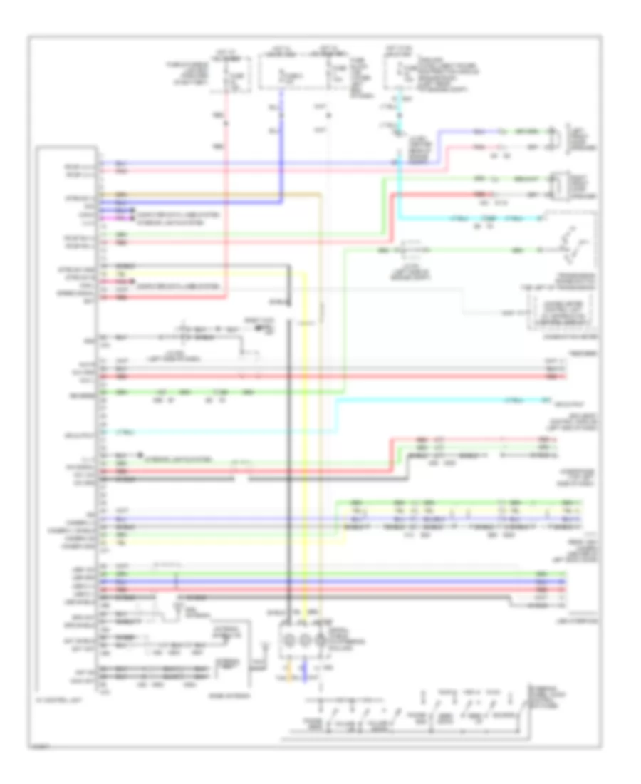
RADIO
Base Radio Wiring Diagram for Nissan NV200 S 2013
List of elements for Base Radio Wiring Diagram for Nissan NV200 S 2013:
- Acc
- Ant +b
- Antenna amp
- Antenna signal
- Audio unit
- Base antenna (if equipped)
- Bat
- D115 m81
- Fr splh (+)
- Fr splh (-)
- Fr sprh (+)
- Fr sprh (-)
- Fuse & fusible link box (forward of battery)
- Fuse 24 15a
- Fuse 5 10a
- Fuse block (j/b) (lower left end of dash)
- Hot at all times
- Hot in on or acc
- Ill (+), light sw
- Ill (-)
- Interior lights system
- Left front door speaker
- M46
- M47
- M500
- M8 d2
- M82
- Nca
- Pnk
- Red
- Right front door speaker
Bose Radio Wiring Diagram, with Navigation for Nissan NV200 S 2013
List of elements for Bose Radio Wiring Diagram, with Navigation for Nissan NV200 S 2013:
- (right kick panel) m57
- 16b
- 20b
- Acc
- Ant on
- Antenna amp
- Antenna satellite
- Aux gnd
- Aux jack
- Aux l
- Aux r
- Av control unit
- B30
- Base antenna
- Bat
- Bcm (body control module) (left end of dash)
- Camera (+)
- Camera (-) shield
- Camera gnd
- Camera on
- Can-h
- Can-l
- Combination meter
- Computer data lines system
- D115 m81
- D500 b58
- E43
- E8 f8
- Fr sp lh (+)
- Fr sp lh (-)
- Fr sp rh (+)
- Fr sp rh (-)
- Fuse & fusible link box (forward of battery)
- Fuse 10a
- Fuse 15a
- Fuse 5 10a
- Fuse block (j/b) (lower left end of dash)
- Gnd
- Gps ant
- Gps antenna
- Gps shield
- Hot at all times
- Hot in on or acc
- Hot in on or start
- Ign
- Ill (-)
- Ill(+)
- Interior lights system
- Ipdm e/r (intelligent power distribution module engine room) (left rear of engine compt)
- J/c e01 (center rear of engine compt)
- J/c f01 (left side of engine compt)
- J/c m02 (left side of dash)
- Left front door speaker
- M13
- M25 m200
- M30
- M501
- M502
- M68
- M69 e7
- M70
- M71
- M73
- M82 m500
- M83 m503
- M84
- M85
- M88
- Main ant
- Mic gnd
- Mic signal
- Mic vcc
- Microphone (top left side of dash)
- Mr output
- Nca
- Phone/ end
- Phone/ send
- Pnk
- R p
- Rear view camera (center of left back door)
- Red
- Reverse
- Right front door
- Sat ant
- Sat shield
- Seek down
- Seek up
- Shield
- Source
- Speaker
- Speed signal
- Spiral cable (in steering column)
- Steering wheel audio control switches
- Strg sw a
- Strg sw b
- Strg sw gnd
- Tan
- Transmission range switch (top left of transmission)
- Unified meter control unit (w/ information control display)
- Usb d (+)
- Usb d (-)
- Usb gnd
- Usb interface
- Usb shield
- Usb vcc
- Volume down
- Volume up
Bose Radio Wiring Diagram, without Navigation for Nissan NV200 S 2013
List of elements for Bose Radio Wiring Diagram, without Navigation for Nissan NV200 S 2013:
- Acc
- Ant +b
- Antenna amp
- Antenna signal
- Audio out +
- Audio out -
- Audio shield
- Audio unit
- Base antenna (if equipped)
- Bat
- Bt antenna
- Bt antenna shield
- Can jumper 1
- Can jumper 2
- Combination meter
- Cont 2
- Cont 5
- Cont 6
- D115 m81
- Fr lh +
- Fr lh -
- Fr rh +
- Fr rh -
- Fuse & fusible link box (forward of battery)
- Fuse 10a
- Fuse 15a
- Fuse 5 10a
- Fuse block (j/b) (lower left end of dash)
- Gnd
- Hot at all times
- Hot in on or acc
- Hot in on or start
- Ign
- Ill (-)
- Ill(+), light sw
- Interior lights system
- J/c m02 (left side of dash)
- Ladder in 1
- Ladder in 2
- Ladder in 3 (gnd)
- Ladder out 1
- Ladder out 2
- Ladder out 3 (gnd)
- Left front door speaker
- M can h
- M can l
- M- can h (terminated)
- M-can h
- M-can l
- M-can l (terminated)
- M200
- M25
- M30
- M43
- M44
- M45
- M500
- M56
- M57 (right kick panel)
- M58
- M59
- M82
- M88 tan
- Mic in +
- Mic in - (gnd)
- Mic power
- Microphone (top left side of dash)
- Mute control
- Nca
- Phone/ end
- Pnk
- Red
- Right front door speaker
- Seek down
- Seek up
- Shield
- Source
- Speed
- Speed signal
- Spiral cable (in steering column)
- Steering wheel audio control switches
- Strg a
- Strg b
- Tel +
- Tel -
- Tel on
- Tel shield
- Unified meter control unit (w/ information display)
- Vol down
- Vol up
SHIFT INTERLOCK
Shift Interlock Wiring Diagram for Nissan NV200 S 2013
List of elements for Shift Interlock Wiring Diagram for Nissan NV200 S 2013:
- Cvt shift selector
- Fuse 10a
- Fuse block (j/b) (lower left end of dash)
- Hot in on or start
- M57 (right kick panel)
- M69 40a
- M69 41a
- Park position switch
- Shift lock solenoid
- Stop lamp switch (top of brake pedal assembly)
STARTING/CHARGING
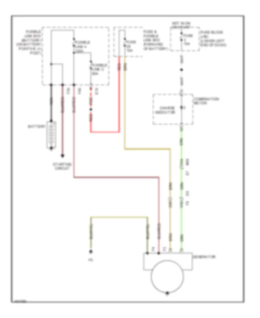
Charging Wiring Diagram for Nissan NV200 S 2013
List of elements for Charging Wiring Diagram for Nissan NV200 S 2013:
- 31b
- 32b
- 33a
- Battery
- Charge indicator
- Combination meter
- E10
- F39
- F40
- Fuse & fusible link box (forward of battery)
- Fuse 10a
- Fuse block (j/b) (lower left end of dash)
- Fusible link a 120a
- Fusible link box (battery) (on battery positive (+) post)
- Fusible link c 80a
- Generator
- Hot in on or start
- M69
- Nca
- Red
- Starting circuit
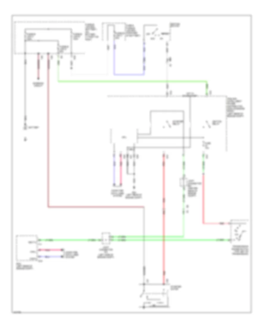
Starting Wiring Diagram for Nissan NV200 S 2013
List of elements for Starting Wiring Diagram for Nissan NV200 S 2013:
- 11b
- 25b
- 96a
- Acc
- Battery
- Can-h
- Can-l
- Charging circuit
- Computer data lines system
- Cpu
- E10
- E16
- E24 (left rear of engine compt)
- E42
- E43
- E44
- E46
- E47
- E48
- Ecm (left rear of engine compt)
- F11
- F27
- F28
- F39
- F40
- Fuse & fusible link box (forward of battery)
- Fuse 10a
- Fusible link a 120a
- Fusible link b 100a
- Fusible link box (battery) (on battery (+) positive post)
- Fusible link d 60a
- Fusible link h 40a
- Hot in on or start
- Ignition relay
- Ignition switch
- Ipdm e/r (intelligent power distribution module engine room) (left rear of engine compt)
- Joint connector e01 (center rear of engine compt)
- Joint connector f01 (left side of engine compt)
- M69
- Nca
- Neut-h
- Off
- Pnk
- Red
- Start
- Starter motor
- Starter relay
- Transmission range switch (top left of transmission)
SUPPLEMENTAL RESTRAINTS
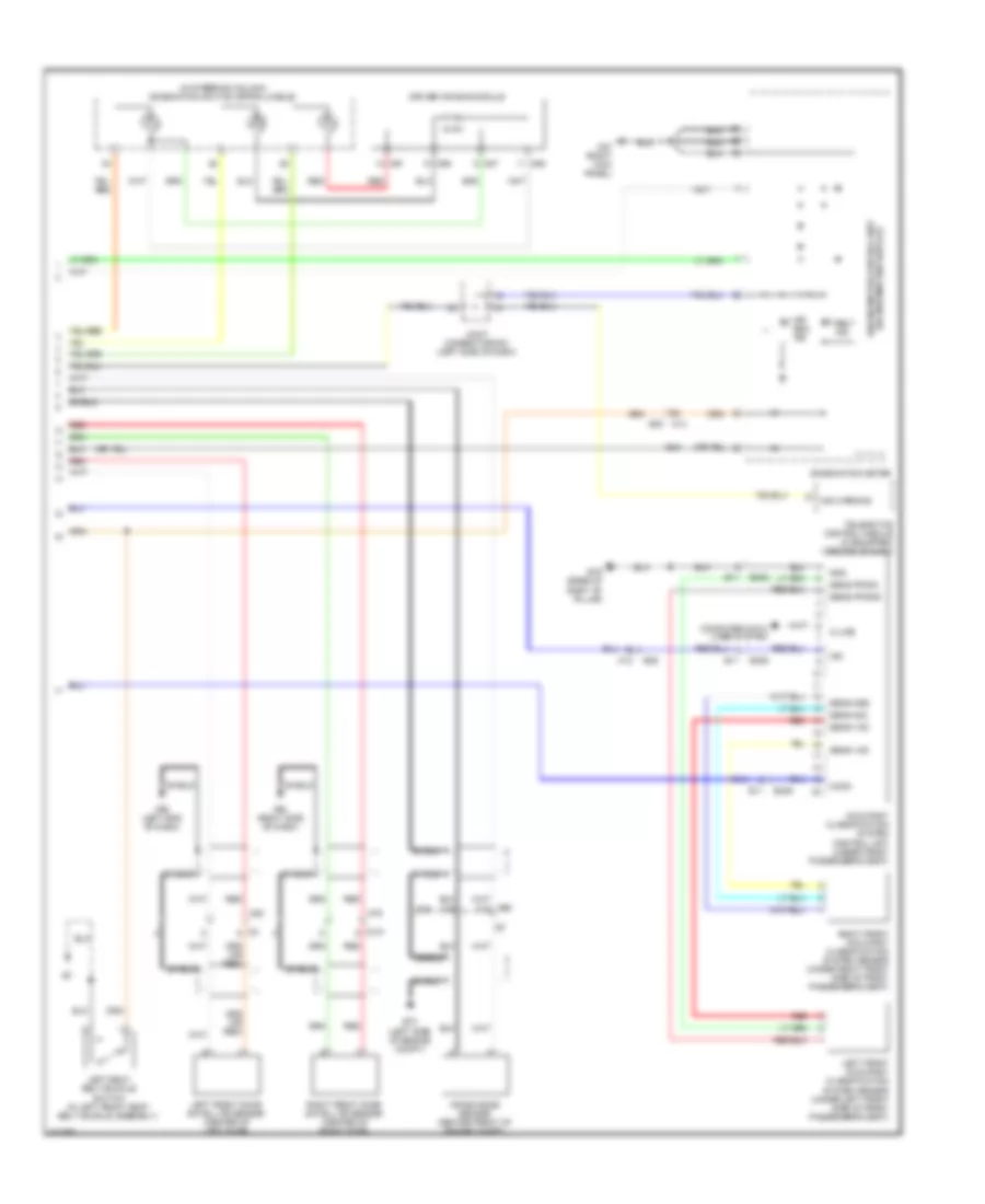
Supplemental Restraints Wiring Diagram (1 of 2) for Nissan NV200 S 2013
List of elements for Supplemental Restraints Wiring Diagram (1 of 2) for Nissan NV200 S 2013:
- (in right front seat belt buckle assembly) right seat belt buckle switch
- (or red)
- (right side of dash) front passenger air bag module
- Air bag diagnosis sensor unit (under center console)
- Air bag w/l
- As1 (+)
- As1 (-)
- As2 (+)
- As2 (-)
- B11
- B12
- B306
- B307
- B37
- B66 (base of left "b" pillar)
- B67 (middle of right "b" pillar)
- C-lh1 (+)
- C-lh1 (-)
- C-rh1 (+)
- C-rh1 (-)
- Can-h
- Can-l
- Computer data lines system
- Cutoff telltale
- Dr1 (+)
- Dr1 (-) & dr2 (-)
- Dr2 (+)
- Eczs1 (+)
- Eczs1 (-)
- Front passenger air bag off indicator
- Fuse 10a
- Fuse block (j/b) (lower left end of dash)
- Gnd
- Hot at all times
- Hot in on or start
- Ign
- Joint connector m01 (left side of dash)
- Left front seat belt pre-tensioner (lap belt) (base of left front "b" pillar)
- Left front side air bag module (outer edge of left front seat back)
- Left front side air bag satellite sensor (base of left "b" pillar)
- Left side curtain air bag module (top of left "a" pillar)
- Lh satellite sens (+)
- Lh satellite sens (-)
- Lh seat belt buckle sw
- M35
- M57 (right kick panel)
- M61 (left end of dash)
- Ods input
- P-lh1 (+)
- P-lh1 (-)
- P-rh1 (+)
- P-rh1 (-)
- Red
- Rh satellite sens (+)
- Rh satellite sens (-)
- Rh seat belt buckle sw
- Right front seat belt pre-tensioner (lap belt) (base of right front "b" pillar)
- Right front side air bag module (outer edge of right front seat back)
- Right front side air bag satellite sensor (base of right "b" pillar)
- Right side curtain air bag module (top of right "a" pillar)
- S-lh (+)
- S-lh (-)
- S-rh (+)
- S-rh (-)
- Seatbelt reminder
- Shield
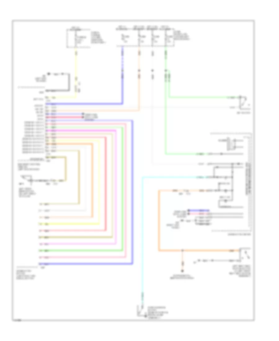
Supplemental Restraints Wiring Diagram (2 of 2) for Nissan NV200 S 2013
List of elements for Supplemental Restraints Wiring Diagram (2 of 2) for Nissan NV200 S 2013:
- (in steering column) combination switch (spiral cable)
- (w/ information display) unified meter control unit
- 71a
- 72a
- 82a
- A/b warning
- Air bag ind
- B11
- B19 (base of right "b" pillar)
- B29
- B306
- Belt ind
- Combination meter
- Comm
- Computer data lines system
- Crash zone sensor (center front of engine compt)
- D101
- Driver air bag module
- E70 (left side of engine compt)
- Gnd
- Ign
- Joint connector-m03 (left side of dash)
- K-line
- Left front door satellite sensor (center of left door)
- Left front occupant classification system sensor (under left front side of front passenger's seat)
- Left seat belt buckle switch (in left front seat belt buckle assembly)
- M12
- M13 b30
- M57 (right kick panel)
- M69
- M75
- M80
- M86
- M87
- M93 (left end of dash)
- M94 (right side of dash)
- Occupant classification system control unit (under front passenger's seat)
- Red
- Right front door satellite sensor (center of right door)
- Right front occupant classification system sensor (under right front side of front passenger's seat)
- Sens fr gnd
- Sens fr sig
- Sens gnd
- Sens sig
- Sens vcc
- Shield
- Telematics control module (if equipped) (center of dash)
TRANSMISSION
Transmission Wiring Diagram for Nissan NV200 S 2013
List of elements for Transmission Wiring Diagram for Nissan NV200 S 2013:
- (not used)
- (top left of transmission) transmission range switch
- 15b
- 20b
- 38b
- 39b
- 92a
- Batt
- Can-h
- Can-l
- Chip select (sel1)
- Clock (sel2)
- Combination meter
- Computer data lines system
- Control valve
- Cvt fluid temp sens
- Cvt fluid temp- erature sensor
- Cvt shift selector
- Cvt unit (left rear of trans- mission)
- D range sw
- Data i/o (sel3)
- E16
- E41 (left rear of engine compt)
- E43
- Ecm (left rear of engine compt)
- F207
- F208
- Fuse & fusible link box (forward of battery)
- Fuse 10a
- Fuse block (j/b) (lower left end of dash)
- Gnd
- Hot at all times
- Hot in on or start
- Interior lights system
- Ipdm e/r (intelligent power distribution module engine room) (left rear of engine compt)
- J/c e01 (center rear of engine compt)
- J/c f01 (left side of engine compt)
- L range sw
- Line press sol vlv
- Line pressure solenoid valve
- Lock-up select solenoid valve
- Lu & select sol vlv
- M57 (right kick panel)
- M69 e7
- N range sw
- O/d control switch
- O/d off ind
- P range sw
- Park position switch
- Pnk
- Power distribution system
- Pri speed sens
- Primary speed sensor (in transmission)
- R range sw
- Red
- Rom assembly
- S/m-a
- S/m-b
- S/m-c
- S/m-d
- Sec oil press sens
- Sec press sol vlv
- Sec speed sens
- Secondary pressure sensor
- Secondary pressure solenoid valve
- Secondary speed sensor (in transaxle)
- Sens power source
- Sensor gnd
- Shift interlock system
- Shift lock solenoid
- Starting/ charging system
- Step motor
- Stop lamp switch (top of brake pedal assembly)
- Stp lmp sw
- Tcc sol valve
- Tcm (transmission control module) (forward of fuse & fusible link box)
- Torque converter clutch solenoid valve
- Unified meter control unit (w/ information display)
- Vign
WARNING SYSTEMS
Chime Wiring Diagram for Nissan NV200 S 2013
List of elements for Chime Wiring Diagram for Nissan NV200 S 2013:
- (w/ information display) unified meter control unit
- 91a
- Acc sw
- B29
- B30
- Bat (f/l)
- Bcm (body control module) (left end of dash)
- Belt ind
- Brake ind
- Buzzer
- Can-h
- Can-l
- Comb sw input 2
- Comb sw input 3
- Comb sw input 4
- Comb sw input 5
- Comb sw output 1
- Comb sw output 2
- Comb sw output 3
- Comb sw output 4
- Comb sw output 5
- Combination meter
- Combination switch (lighting & turn signal switch)
- Comp sw input 1
- Computer data lines system
- Door ind
- Dr door sw
- Fuse & fusible link box (forward of battery)
- Fuse 10a
- Fuse block (j/b) (lower left end of dash)
- Fusible link j 40a
- Gnd
- Hot at all times
- Hot in on or acc
- Hot in on or start
- Ign sw
- Key sw
- Key switch
- Left front door switch (on left front "b" pillar)
- Left seat belt buckle switch (in left front seat belt buckle assembly)
- M12
- M13
- M18
- M19
- M20
- M28
- M57 (right kick panel)
- M61 (left end of dash)
- M69
- Parking brake switch (base of parking brake lever assembly)
- Pnk
- Red
Tire Pressure Monitoring Wiring Diagram for Nissan NV200 S 2013
List of elements for Tire Pressure Monitoring Wiring Diagram for Nissan NV200 S 2013:
- 18a
- 19a
- 20a
- 21a
- 27a
- 28a
- 29a
- 30a
- B30
- Bcm (body control module) (left end of dash)
- Buzzer
- Can-h
- Can-l
- Combination meter
- Computer data lines system
- Data fl
- Data fr
- Data rl
- Data rr
- Fuse 10a
- Fuse block (j/b) (lower left end of dash)
- Gnd
- Gnd fl
- Gnd fr
- Gnd rl
- Gnd rr
- Hazard sw
- Hot at all times
- Hot in on or start
- Ign
- Left front tire pressure receiver (rear of left front wheelwell)
- Left rear tire pressure receiver (rear of left rear wheelwell)
- Low tire pressure warning control unit (right side of dash)
- M13
- M18
- M57 (right kick panel)
- M69
- Pnk
- Red
- Right front tire pressure receiver (rear of right front wheelwell)
- Right rear tire pressure receiver (rear of right rear wheelwell)
- Rssi fl
- Rssi fr
- Rssi rl
- Rssi rr
- Tire pressure ind
- Unified meter control unit (w/ information display)
- Vcc fl
- Vcc fr
- Vcc rl
- Vcc rr
WIPER/WASHER
Wiper/Washer Wiring Diagram for Nissan NV200 S 2013
List of elements for Wiper/Washer Wiring Diagram for Nissan NV200 S 2013:
- (center rear of engine compt) joint connector e01
- 100a
- 99a
- Bat (f/l)
- Bcm (body control module) (left end of dash)
- Can-h
- Can-l
- Combination meter
- Combination switch (wiper & washer switch)
- Computer data lines system
- Cpu
- E24 (left rear of engine compt)
- E45
- E46
- E47
- E48
- Front washer motor (in washer reservoir)
- Front wiper high relay
- Front wiper motor (left rear of engine compt)
- Front wiper relay
- Fuse & fusible link box (forward of battery)
- Fuse 10a
- Fuse 30a
- Fuse block (j/b) (lower left end of dash)
- Fusible link j 40a
- Gnd
- High
- Hot at all times
- Hot in on or start
- Ignition relay
- Input 1
- Input 2
- Input 3
- Input 4
- Input 5
- Ipdm e/r (intelligent power distribution module engine room) (left rear of engine compt)
- Low
- M18
- M19
- M28
- M61 (left end of dash)
- M69
- M69 24a
- M69 91a
- Move
- Output 1
- Output 2
- Output 3
- Output 4
- Output 5
- Pnk
- Red
- Stop
- Unified meter control unit (w/ information display)
- Washer fluid level switch (in washer fluid reservoir)
- Washer ind

 Čeština
 Dansk
Dansk Deutsch
 Ελληνικά
 English
 Español
 Suomi
Suomi Français
 Français
 עברית
עברית Hrvatski
 Magyar
 Italiano
 日本語
日本語 한국어
한국어 Nederlands
 Polski
 Português
 Português
 Română
 Русский
 Slovenčina
 Slovenščina
 Svenska
 Türkçe
 中文 (中国)