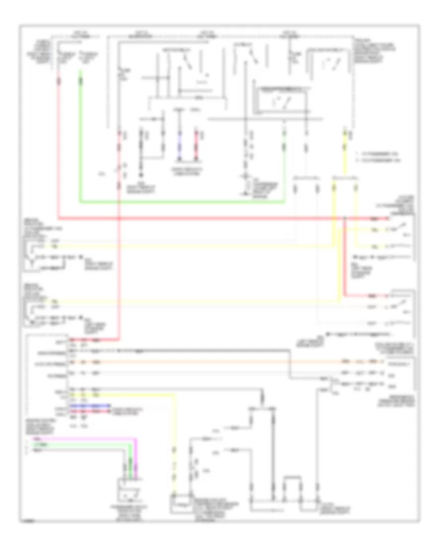
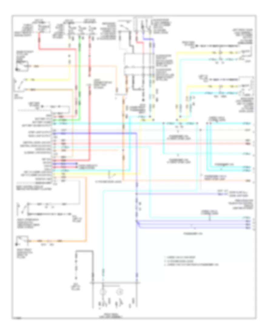
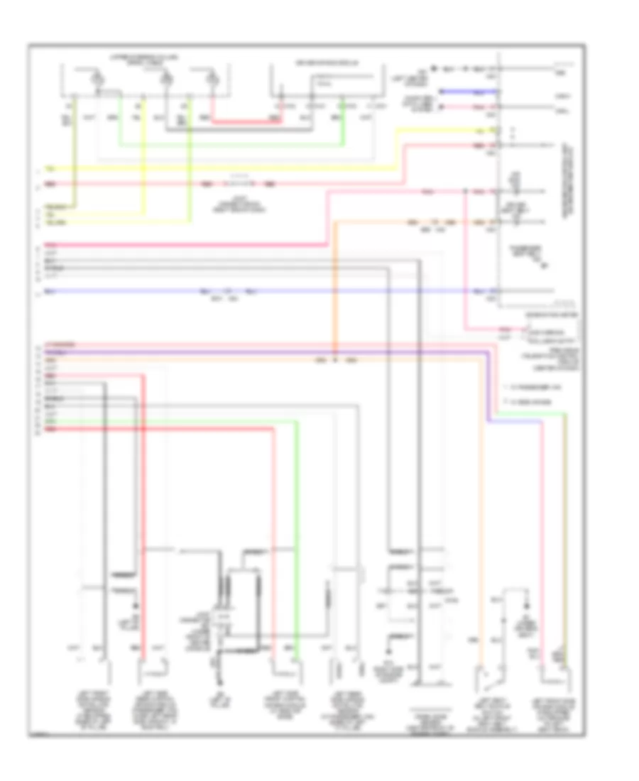
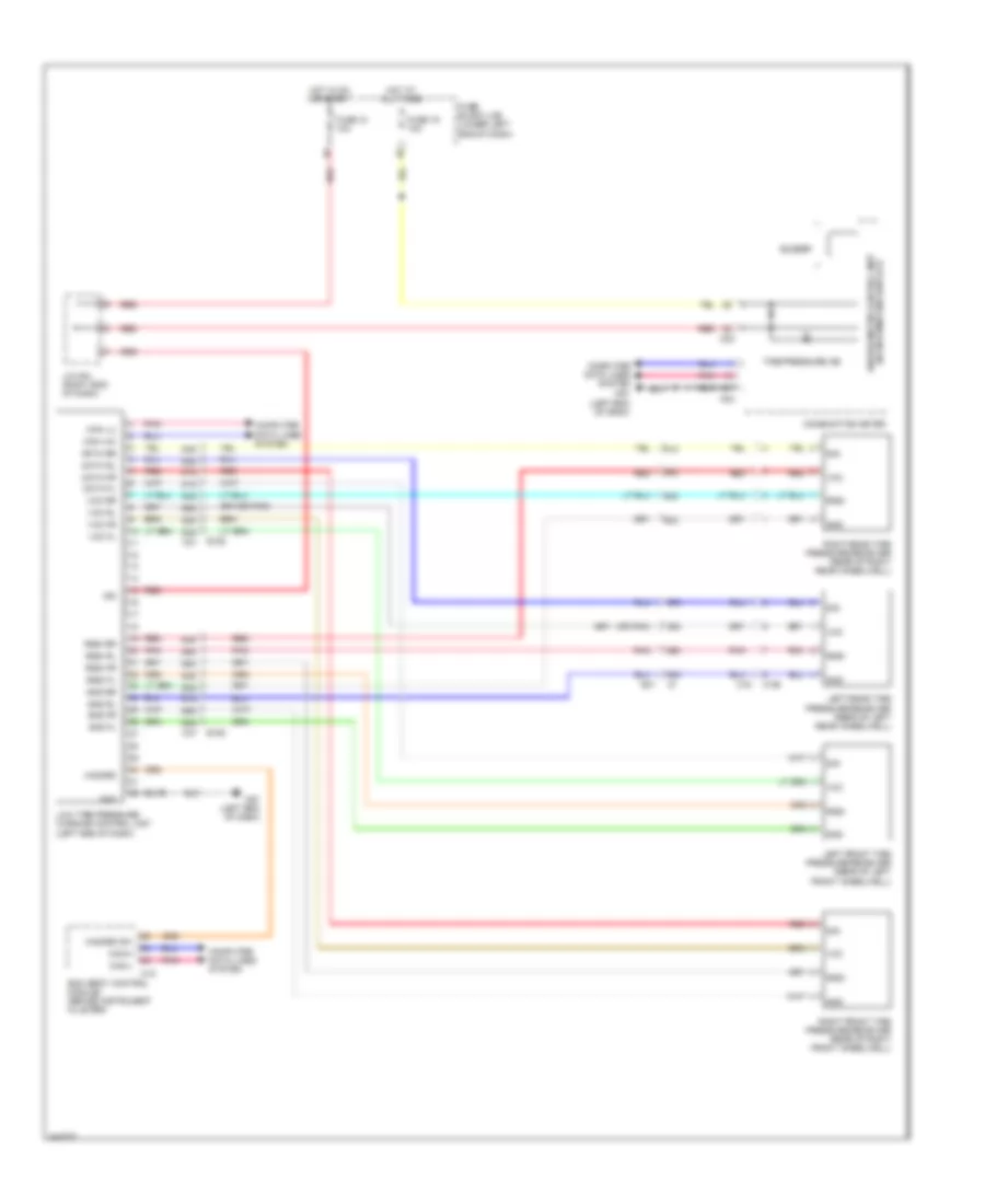
AIR CONDITIONING
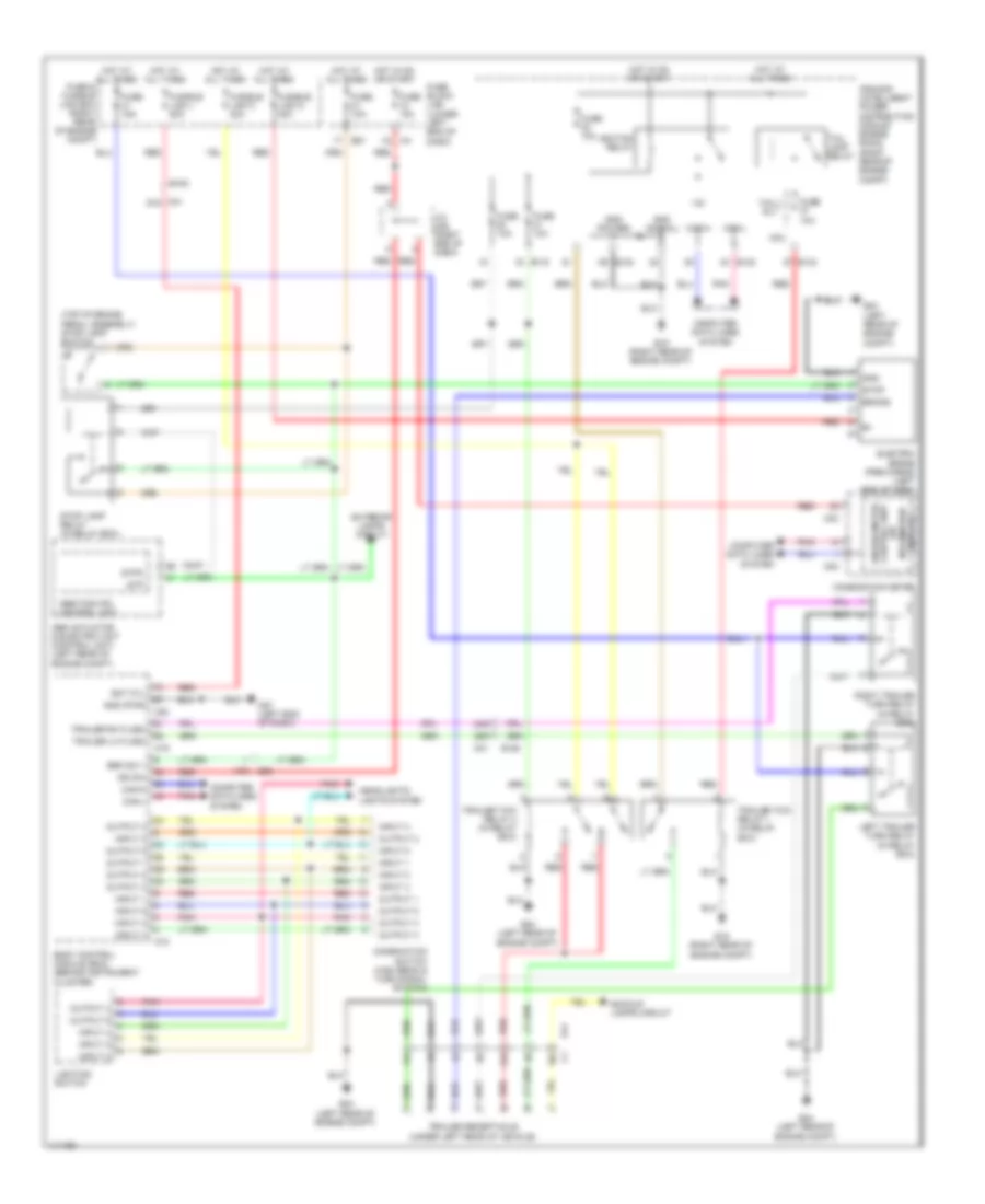
Automatic A/C Wiring Diagram (1 of 3) for Nissan NVHD SL 2014 3500
 https://portal-diagnostov.com/license.html
Automotive Electricians Portal FZCO
Automotive Electricians Portal FZCO
https://portal-diagnostov.com/license.html
https://portal-diagnostov.com/license.html
Automotive Electricians Portal FZCO
Automotive Electricians Portal FZCO
List of elements for Automatic A/C Wiring Diagram (1 of 3) for Nissan NVHD SL 2014 3500:
- (near fuse block (j/b)) front blower motor relay 2
- 12g
- 22g
- 47g
- 48g
- 90j
- 96j
- Acc
- Amb sens
- Ambient sensor (center of front grille)
- B20
- B7 (under driver's seat)
- Batt
- Can-h
- Can-l
- Comp on
- Computer data lines system
- E152
- F14
- Fan f/b
- Fan gate
- Fan on
- Front air control
- Front blower motor relay 1
- Fuse 10a
- Fuse 15a
- Fuse block (j/b) (lower left end of dash)
- Gnd
- Hot at all times
- Hot in on or start
- Ign pwr sply
- Ignition switch
- Ill+
- Ill-
- In car sens
- In-vehicle sensor (lower left side of dash)
- Int sens
- Intake sensor (left side of hvac unit)
- Interior lights system
- Joint connector m04 (right end of dash)
- Lin
- M31
- M32
- M39
- M53
- M56
- M57 (left end of dash)
- M79 (right end of dash)
- Off
- Pnk
- Pwr gnd
- R def on
- Rear air control
- Rear blower motor (on rear hvac unit)
- Red
- Rr fan
- Rr fan pw/m
- Rr fan sw
- Rr sw vcc
- Rr temp
- Rr temp sw
- Sens gnd
- Start
- Sun sens
- Sunload sensor (top left side of dash)
- Sv sply
- Vactr
- Vign2
- Water valve (5.6l) (right rear of engine)
- Wtr val close(+)
- Wtr val open(-)
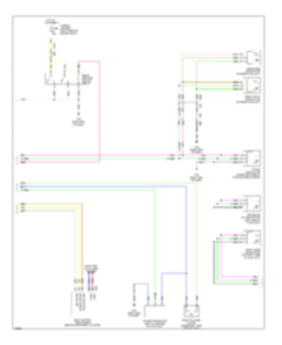
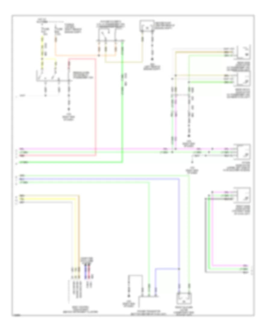
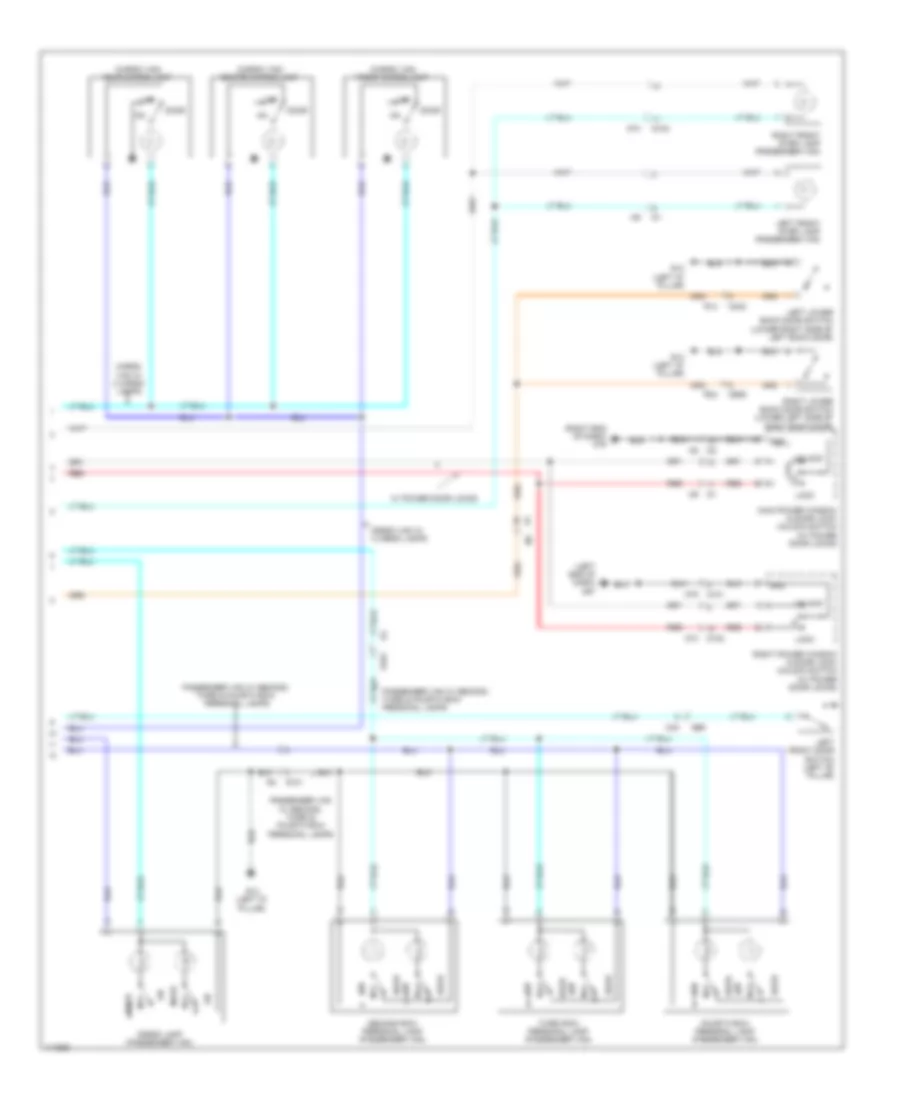
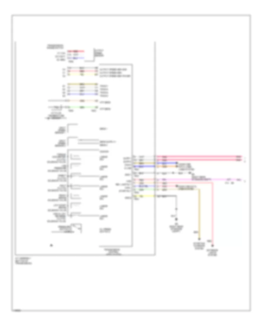
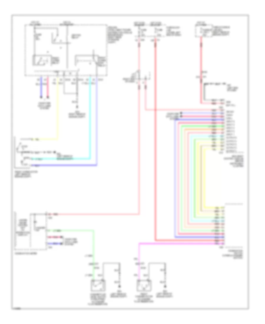
Automatic A/C Wiring Diagram (2 of 3) for Nissan NVHD SL 2014 3500
List of elements for Automatic A/C Wiring Diagram (2 of 3) for Nissan NVHD SL 2014 3500:
- (right end of dash)
- 79j
- 88j
- 89j
- Air con sw
- B20
- B200
- B25
- Blowr fan sw
- Body control module (bcm) (behind instrument cluster)
- Can-h
- Can-l
- Computer data lines system
- Driver air mix door motor (left side of hvac unit)
- E152 m31
- Front blower motor (under right end of hvac unit)
- Front mode door motor (top right side of hvac unit)
- Fuse 30a
- Fusible link box (right rear of engine compt)
- Hot at all times
- Intake door motor (upper left side of hvac blower housing)
- M18
- M32
- M79
- M79 (right end of dash)
- Pnk
- Power transistor (bottom center of hvac unit)
- Rear air mix door motor (on rear hvac unit)
- Rear blower motor relay
- Rear defg sw
- Rear mode door motor (on rear hvac unit)
- Red
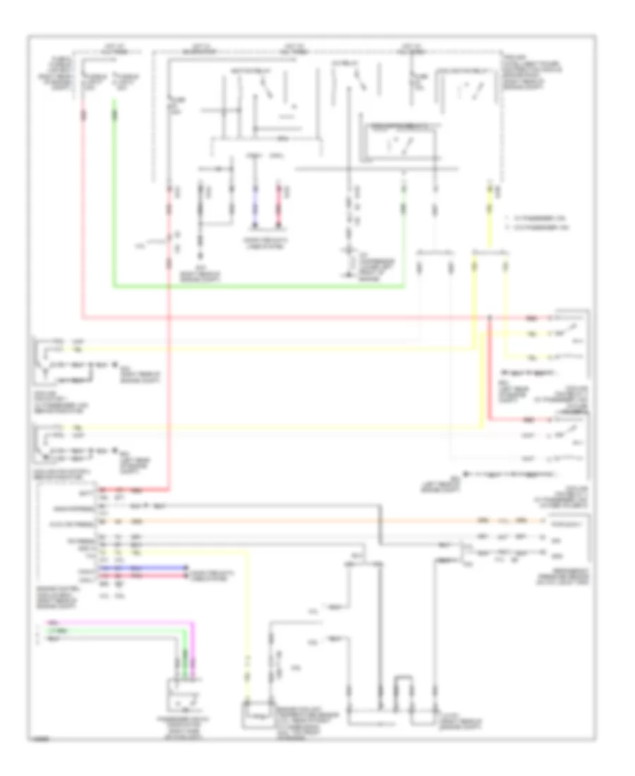
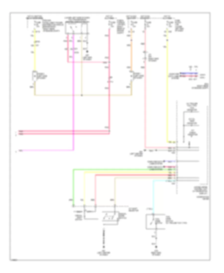
Automatic A/C Wiring Diagram (3 of 3) for Nissan NVHD SL 2014 3500
List of elements for Automatic A/C Wiring Diagram (3 of 3) for Nissan NVHD SL 2014 3500:
- 4.0l
- 5.6l
- A/c compressor (lower left front of engine)
- A/c relay
- Avcc (pd press)
- Batt
- Can-h
- Can-l
- Computer data lines system
- Cooling fan motor 1 (w/ passenger van) (behind radiator)
- Cooling fan motor 2 (behind radiator)
- Cooling fan relay 1
- Cooling fan relay 2
- Cooling fan relay 3 (w/ passenger van) (in fuse holder 2)
- Cooling fan relay 4 (w/ passenger van) (in fuse holder 2)
- Cpu
- E119
- E120
- E121
- E122
- E124
- E15 (right rear of engine compt)
- E16
- E24 (left rear of engine compt)
- E77
- Engine control module (ecm) (right rear of engine compt)
- Engine coolant temperature sensor (4.ol: rear of right cylinder bank) (5.6l: top front of engine)
- F14
- F203
- F32
- F36
- F54
- F72
- F77
- Fuse & fusible link box (right rear of engine compt)
- Fuse 10a
- Fuse 20a
- Fusible link m 40a
- Fusible link p 40a
- Gnd
- Gnd a
- Gnda-pdpress
- Hot at all times
- Hot in on or start
- Ignition relay
- Ipdm e/r (intelligent power distribution module engine room) (right rear of engine compt)
- J/c f01 (right rear of engine compt)
- Passenger air mix door motor (right side of hvac unit)
- Pd press
- Pnk
- Pwr suply
- Red
- Refrigerant pressure sensor (on a/c liquid tank)
- Sig
- W/ passenger van
- W/o passenger van
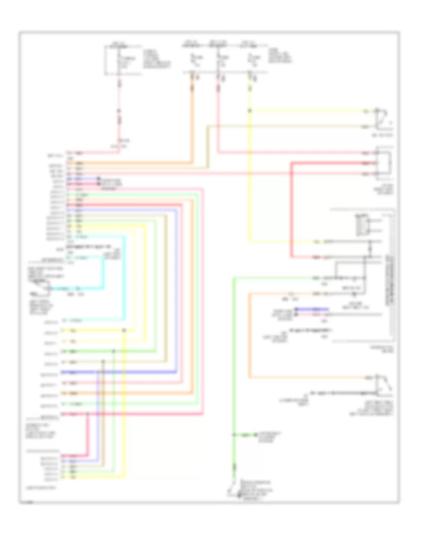
Manual A/C Wiring Diagram (1 of 3) for Nissan NVHD SL 2014 3500
List of elements for Manual A/C Wiring Diagram (1 of 3) for Nissan NVHD SL 2014 3500:
- (near fuse block (j/b)) front blower motor relay 2
- 12g
- 22g
- 47g
- 48g
- 90j
- 96j
- Acc
- Amb sens
- Ambient sensor (center of front grille)
- B20
- B7 (under driver's seat)
- Batt
- Can-h
- Can-l
- Comp on
- Computer data lines system
- E152
- F14
- Fan f/b
- Fan gate
- Fan on
- Front air control
- Front blower motor relay 1
- Fuse 10a
- Fuse 15a
- Fuse block (j/b) (lower left end of dash)
- Gnd
- Hot at all times
- Hot in on or start
- Htr pump
- Ign
- Ignition switch
- Ill +
- Ill+
- Ill-
- Int sens
- Intake sensor (left side of hvac unit)
- Interior lights system
- Joint connector m04 (right end of dash)
- Lin
- M31
- M32
- M39
- M49
- M51
- M57 (left end of dash)
- M79 (right end of dash)
- Off
- Pnk
- Pwr gnd
- R def on
- Rear air control (passenger van)
- Rear blower motor (w/ passenger van) (on rear hvac unit)
- Red
- Rr fan
- Rr fan rw/m
- Rr fan sw
- Rr sw vcc
- Rr tem
- Rr temp sw
- Sens gnd
- Start
- Sv sply
- Vactr
- Vign2
- Water valve (5.6l) (right rear of engine)
- Wtr vlv close(+)
- Wtr vlv open(-)
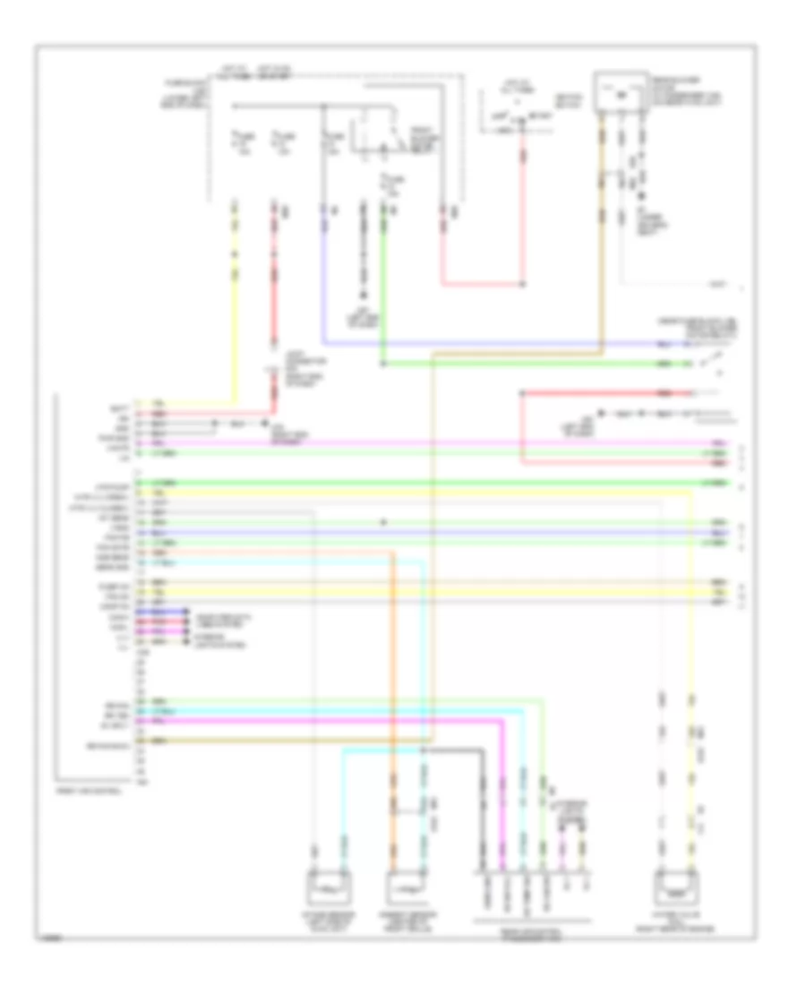
Manual A/C Wiring Diagram (2 of 3) for Nissan NVHD SL 2014 3500
List of elements for Manual A/C Wiring Diagram (2 of 3) for Nissan NVHD SL 2014 3500:
- (in fuse holder 2) (4.0l w/ passenger van) heater pump relay
- (right end of dash)
- 50g
- 79j
- 88j
- 89j
- Air con sw
- B20
- B200
- B25
- Blowr fan sw
- Body control module (bcm) (behind instrument cluster)
- Can-h
- Can-l
- Computer data lines system
- E152
- E24 (left rear of engine compt)
- Front blower motor (under right end of hvac unit)
- Front mode door motor (top right side of hvac unit)
- Fuse 10a
- Fuse 30a
- Fusible link box (right rear of engine compt)
- Heater pump (center rear of engine compt)
- Hot at all times
- Intake door motor (upper left side of hvac blower housing)
- M18
- M31
- M32
- M79
- M79 (right end of dash)
- Pnk
- Power transistor (bottom center of hvac unit)
- Rear air mix door motor (w/ passenger van) (on rear hvac unit)
- Rear blower motor relay (passenger van)
- Rear defg sw
- Rear mode door motor (w/ passenger van) (on rear hvac unit)
- Red
Manual A/C Wiring Diagram (3 of 3) for Nissan NVHD SL 2014 3500
List of elements for Manual A/C Wiring Diagram (3 of 3) for Nissan NVHD SL 2014 3500:
- (behind radiator) (w/ passenger van) cooling fan motor 1
- (behind radiator) cooling fan motor 2
- (in fuse holder-2) (w/ passenger van) cooling fan relay 3
- 4.0l
- 5.6l
- A/c compressor (lower left front of engine)
- A/c relay
- Avcc (pd press)
- Batt
- Can-h
- Can-l
- Computer data lines system
- Cooling fan relay 1
- Cooling fan relay 2
- Cooling fan relay 4 (w/ passenger van) (in fuse holder-2)
- Cpu
- E119
- E120
- E121
- E122
- E124
- E15 (right rear of engine compt)
- E16
- E24 (left rear of engine compt)
- E77
- Engine control module (ecm) (right rear of engine compt)
- Engine coolant temperature sensor (4.ol: rear of right cylinder bank) (5.6l: top front of engine)
- F14
- F203
- F32
- F36
- F54
- F72
- F77
- Fuse & fusible link box (right rear of engine compt)
- Fuse 10a
- Fuse 20a
- Fusible link m 40a
- Fusible link p 40a
- Gnd
- Gnd a
- Gnda-pdpress
- Hot at all times
- Hot in on or start
- Ignition relay
- Ipdm e/r (intelligent power distribution module engine room) (right rear of engine compt)
- J/c f01 (right rear of engine compt)
- Passenger air mix door motor (right side of hvac unit)
- Pd press
- Pnk
- Pwr suply
- Red
- Refrigerant pressure sensor (on a/c liquid tank)
- Sig
- W/ passenger van
- W/o passenger van
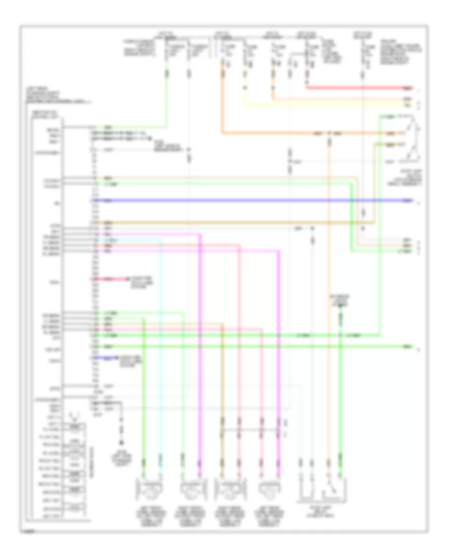
ANTI-LOCK BRAKES
Anti-lock Brakes Wiring Diagram (1 of 2) for Nissan NVHD SL 2014 3500
List of elements for Anti-lock Brakes Wiring Diagram (1 of 2) for Nissan NVHD SL 2014 3500:
- (left rear of engine compt) abs actuator & electric unit (control unit)
- 12c
- 13c
- 14c
- 15c
- Abs/tcs/vdc control unit
- Bs sol
- Can-h
- Can-l
- Computer data lines system
- E119
- E125
- E126 (left side of engine compt)
- E127
- E41
- E51
- Exterior lights system
- Fl in sol
- Fl out sol
- Fl sens+
- Fl sens-
- Fr in sol
- Fr out sol
- Fr sens+
- Fr sens-
- Fuse & fusible link box (right rear of engine compt)
- Fuse 10a
- Fuse block (j/b) (lower left end of dash)
- Fusible link f 50a
- Fusible link l 30a
- Gnd 1
- Gnd 2
- Gnd-3
- Hot at all times
- Hot in acc or on
- Hot in on or start
- Hsv1 mc1
- Hsv2 mc2
- Ign-1
- Ign-2
- Ipdm e/r (intelligent power distribution module engine room) (right rear of engine compt)
- Lbl
- Left front wheel sensor (on left front wheel hub assembly)
- Left rear wheel sensor (on left rear wheel hub assembly)
- M39
- Mot (+)
- Mot (-)
- Mtr power 2
- Mtr power-1
- Pnk
- Red
- Right front wheel sensor (on right front wheel hub assembly)
- Right rear wheel sensor (on right rear wheel hub assembly)
- Rl in sol
- Rl out sol
- Rl sens+
- Rl sens-
- Rr in sol
- Rr out sol
- Rr sens+
- Rr sens-
- Solenoid valve
- Stop lamp relay (in relay box)
- Stop lamp switch (top of brake pedal assembly)
- Stp
- Stp2
- Stpo
- Usv1 mc1
- Usv2 mc2
- Vdc off
- Yg can-h
- Yg can-l
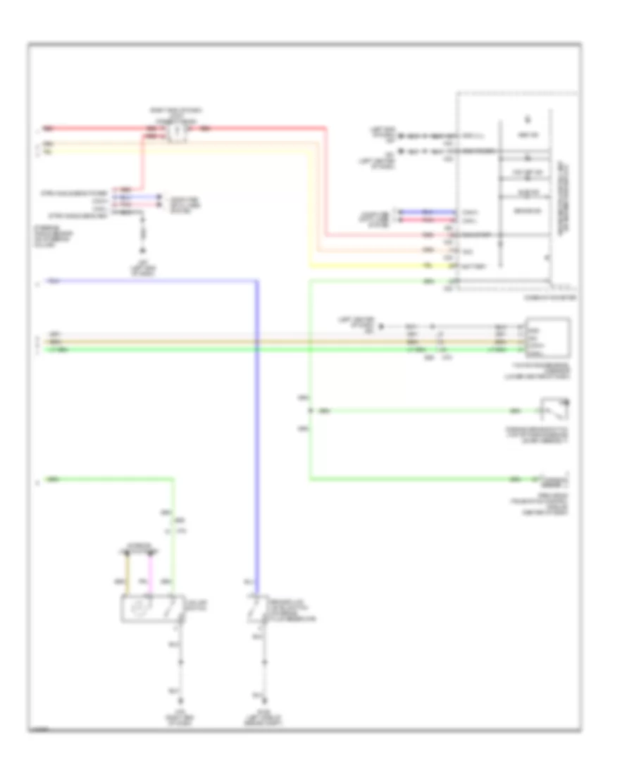
Anti-lock Brakes Wiring Diagram (2 of 2) for Nissan NVHD SL 2014 3500
List of elements for Anti-lock Brakes Wiring Diagram (2 of 2) for Nissan NVHD SL 2014 3500:
- (left center of dash) m61
- (left end of dash) m57
- (right end of dash) joint connector-m04
- Abs ind
- Acc
- Battery
- Brake fluid level switch (on brake fluid reservoir)
- Brake ind
- Can-h
- Can-l
- Combination meter
- Computer data lines system
- E126 (left side of engine compt)
- E55
- Gnd
- Gnd (ill)
- Gnd (power)
- Ign
- Interior lights system
- M23
- M24
- M57 (left end of dash)
- M61 (left center of dash)
- M78
- M79 (right end of dash)
- Parking brake
- Parking brake switch (top of parking brake lever assembly)
- Pnk
- Pre-wiring (telematics control module) (center of dash)
- Red
- Run start
- Slip ind
- Steering angle sensor (on steering column)
- Strg angle sens gnd
- Strg angle sens power
- Unified meter control unit (w/ information display)
- Vdc off ind
- Vdc off switch
- Yaw rate/side/decel g sensor (lower center of dash)
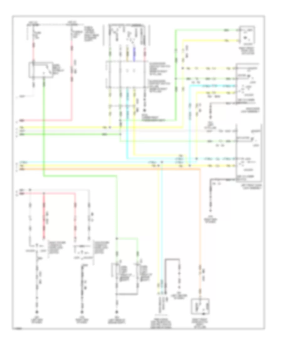
ANTI-THEFT
Forced Entry Wiring Diagram (1 of 2) for Nissan NVHD SL 2014 3500
List of elements for Forced Entry Wiring Diagram (1 of 2) for Nissan NVHD SL 2014 3500:
- (right rear of engine compt) ipdm e/r
- +ig
- Acc sw
- B132 (under front passenger's seat)
- B69
- Bat (f/l)
- Bat (fuse)
- Batt saver output
- Body control module (bcm) (behind instrument cluster)
- Buzzer
- Can h
- Can l
- Can-h
- Can-l
- Cdl lock sw
- Cdl unlock sw
- Closed
- Combination meter
- Computer data lines system
- Cpu
- D402
- D606
- Door ind
- Door lock output
- Door sw (as)
- Door sw (dr)
- Door sw (rl)
- Door sw (rr)
- Door unlck out (dr)
- Dr unlck out (other)
- E122
- E124
- E15 (right rear of engine compt)
- Exterior lights system
- Fuse 10a
- Fuse block (j/b) (lower left end of dash)
- Gnd
- Gnd (pwr)
- Gnd (sig)
- H/lp hi
- H/lp lo
- Headlights system
- Horn rly cont
- Horns system
- Hot at all times
- Hot in on or acc
- Hot in on or start
- Ign sw
- Ignition relay
- Inserted
- Interior lights system
- J/c m04 (right end of dash)
- Key cyl lock sw
- Key cyl unlock sw
- Key sw
- Key switch
- Left front door switch (left "b" pillar)
- Left lower back door switch (lower right side of left back door)
- Lh flasher output
- M18
- M19
- M20
- M23
- M24
- M39
- M40
- M57 (left end of dash)
- M61 (left center of dash)
- M84 b101
- Open
- Pnk
- Power
- R13 (left "d" pillar)
- R14
- R24
- Red
- Remote keyless entry receiver (if equipped) (right center of dash)
- Removed
- Rh flasher output
- Right lower back door switch (lower left side of right back door)
- Right upper back door switch (above right rear door in roof)
- Room lamp output
- Secondary sliding door switch (w/ high roof) (lower rear of sliding door)
- Security ind
- Security ind output
- Signal
- Sliding door contact switch (door) (base of right "b" pillar)
- Sliding door contact switch (pillar) (base of right "b" pillar)
- Sliding door switch (base of right "c" pillar)
- Unified meter control unit (w/ information display)
Forced Entry Wiring Diagram (2 of 2) for Nissan NVHD SL 2014 3500
List of elements for Forced Entry Wiring Diagram (2 of 2) for Nissan NVHD SL 2014 3500:
- 91g
- Actuator
- B101
- B132 (under front passenger's seat)
- Back door lock assembly
- Closed
- Cpu
- D101
- D101 m75
- D102
- Door lock
- Door unlock
- E152
- E24 (left rear of engine compt)
- E71
- Fuse & fusible link box (right rear of engine compt)
- Fuse 15a
- Fusible link j 40a
- Gnd
- Horn (high) (left front of engine e13 compt)
- Horn (low) (left front of engine e72 compt)
- Horn relay (in relay box)
- Hot at all times
- Key cylinder switch
- Left front door lock assembly
- Lock
- M2 r2
- M31
- M57 (left end of dash)
- M61 (left center of dash)
- M74
- M75
- M79 (right end of dash)
- M8 d2
- M84
- M84 b101
- M9 d1
- Main power window & door lock/ unlock switch
- Motor
- Open
- Pre-wiring for telematics control module (center of dash)
- R1 m1
- R13 (left "d" pillar)
- R24 d606
- Red
- Right front door lock actuator
- Right front door switch (right "b" pillar)
- Right power window & door lock/ unlock switch
- Sliding door contact switch (door) (base of right "b" pillar)
- Sliding door contact switch (pillar) (base of right "b" pillar)
- Sliding door lock assembly
- Unlock
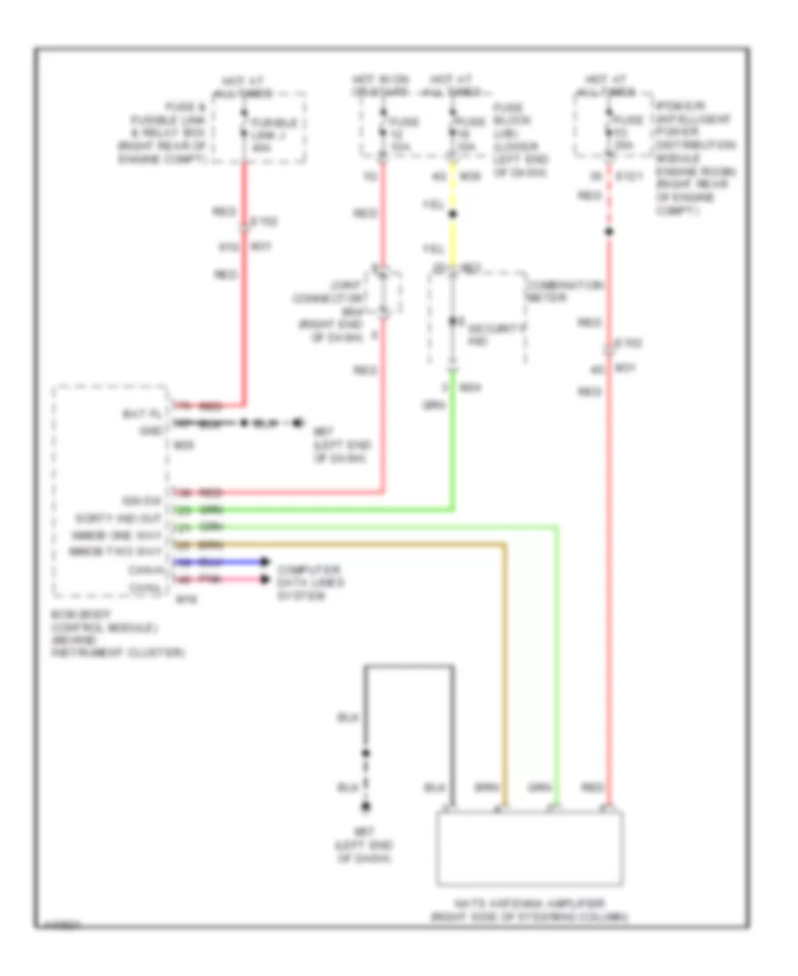
Immobilizer Wiring Diagram for Nissan NVHD SL 2014 3500
List of elements for Immobilizer Wiring Diagram for Nissan NVHD SL 2014 3500:
- Bat fl
- Bcm (body control module) (behind instrument cluster)
- Can-h
- Can-l
- Combination meter
- Computer data lines system
- E121
- E152
- Fuse & fusible link & relay box (right rear of engine compt)
- Fuse 10a
- Fuse 20a
- Fuse block (j/b) (lower left end of dash)
- Fusible link j 40a
- Gnd
- Hot at all times
- Hot in on or start
- Ign sw
- Immob one way
- Immob two way
- Ipdm e/r (intelligent power distribution module engine room) (right rear of engine compt)
- Joint connector m04 (right end of dash)
- M18
- M20
- M23
- M24
- M31 4g
- M31 91g
- M39
- M57 (left end of dash)
- Nats antenna amplifier (right side of steering column)
- Pnk
- Red
- Scrty ind out
- Security ind
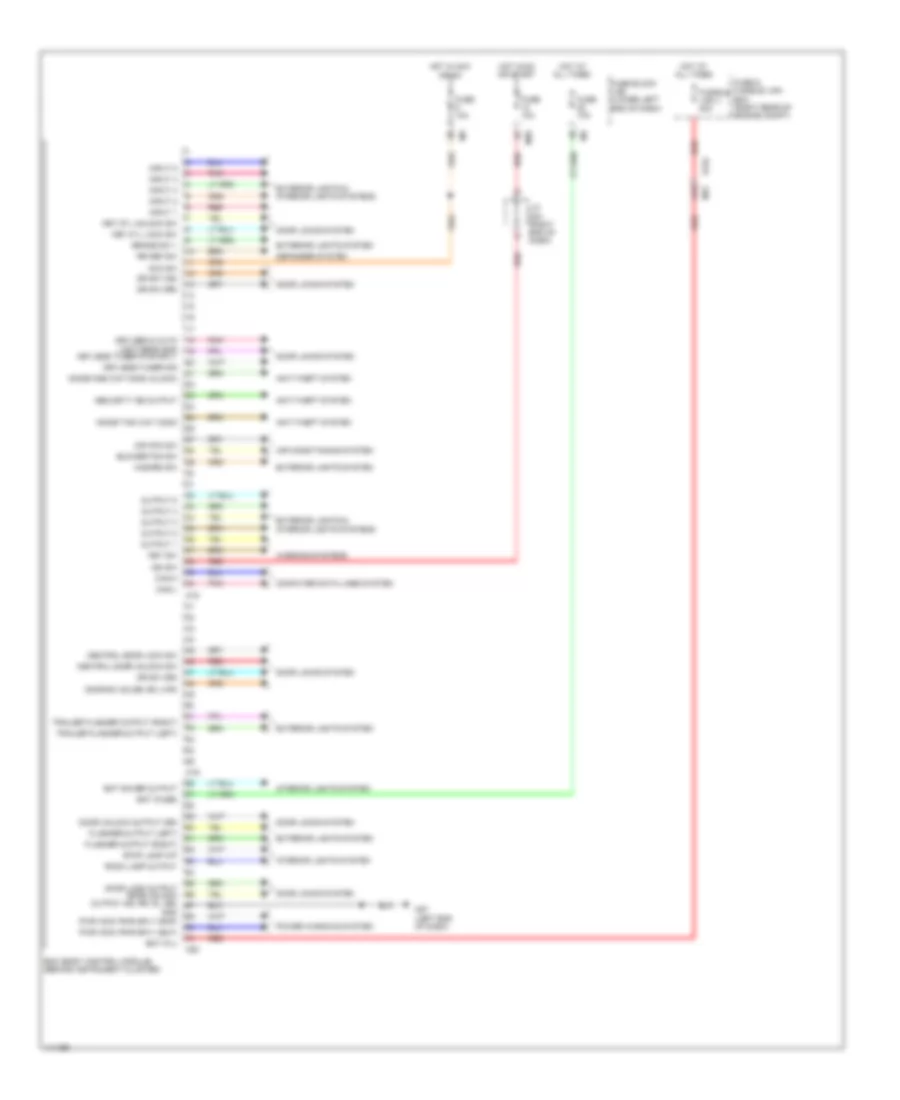
BODY CONTROL MODULES
Body Control Modules Wiring Diagram for Nissan NVHD SL 2014 3500
List of elements for Body Control Modules Wiring Diagram for Nissan NVHD SL 2014 3500:
- 91g
- Acc sw
- Air con sw
- Air conditioning system
- Anti-theft system
- Bat (f/l)
- Bat (fuse)
- Bat saver output
- Bcm (body control module) (behind instrument cluster)
- Blower fan sw
- Brake sw 1
- Can-h
- Can-l
- Central door lock sw
- Central door unlock sw
- Computer data lines system
- Defogger system
- Door lock output door unlock output (as, rr, rl, bd)
- Door locks system
- Door sw (slide, bk lwr)
- Door unlock output (dr)
- Dr sw (as)
- Dr sw (dr)
- Dr sw (rr)
- E152
- Exterior lights & interior lights systems
- Exterior lights system
- Flasher output (left)
- Flasher output (right)
- Fuse & fusible link box (right rear of engine compt)
- Fuse 10a
- Fuse block (j/b) (lower left end of dash)
- Fusible link j 40a
- Gnd
- Hazard sw
- Hot at all times
- Hot in acc or on
- Hot in on or start
- Ign sw
- Immob one way comm (clock)
- Immob two way comm
- Input 1
- Input 2
- Input 3
- Input 4
- Input 5
- Interior lights system
- J/c m04 (right end of dash)
- Key cyl lock sw
- Key cyl unlock sw
- Key sw
- Keyless & auto light sens gnd
- Keyless tuner pwr sply
- Keyless tuner sig
- M18
- M19
- M20
- M31
- M39
- M57 (left end of dash)
- Output 1
- Output 2
- Output 3
- Output 4
- Output 5
- Pnk
- Power windows system
- Pwr wdw pwr sply (bat)
- Pwr wdw pwr sply (rap)
- Red
- Room lamp output
- Rr def sw
- Security ind output
- Stop lamp o/p
- Trailer flasher output (left)
- Trailer flasher output (right)
- Warning systems
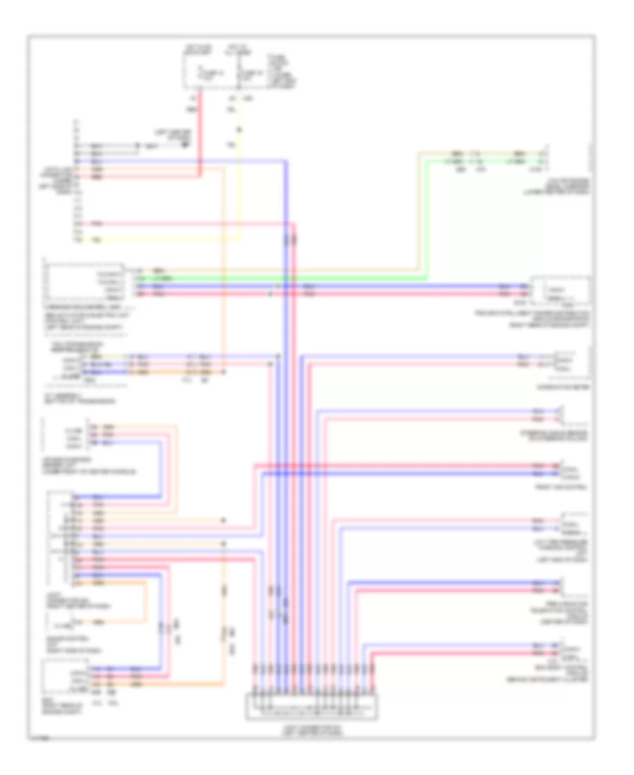
COMPUTER DATA LINES
Computer Data Lines Wiring Diagram for Nissan NVHD SL 2014 3500
List of elements for Computer Data Lines Wiring Diagram for Nissan NVHD SL 2014 3500:
- (left center of dash) m61
- 21g
- 4.0l
- 5.6l
- A/t assembly (bottom of transmission)
- Abs actuator & electric unit (control unit) (left rear of engine compt)
- Abs/tcs/vdc control unit
- Air bag diagnosis sensor unit (under front of center console)
- Bcm (body control module) (behind instrument cluster)
- Can-h
- Can-l
- Combination meter
- Cpu
- Data link connector (under left side of dash)
- E122
- E152
- E16
- E55
- E77
- Ecm (right rear of engine compt)
- F14
- F502
- Front air control
- Fuse 12 10a
- Fuse 19 10a
- Fuse block (j/b) (lower left end of dash)
- Hot at all times
- Hot in on or start
- Ipdm e/r (intelligent power distribution module engine room) (right rear of engine compt)
- Joint connector m01 (left center of dash)
- Joint connector m02 (right center of dash)
- K-line
- Low tire pressure warning control unit (left end of dash)
- M108
- M18
- M31
- M39
- M78
- Pnk
- Pre-wiring for telematics control module (center of dash)
- Red
- Sonar control unit (right side of dash)
- Steering angle sensor (on steering column)
- Tcm (transmission control module)
- Yaw rate/side/ decel g-sensor (lower center of dash)
- Yg can-h
- Yg can-l
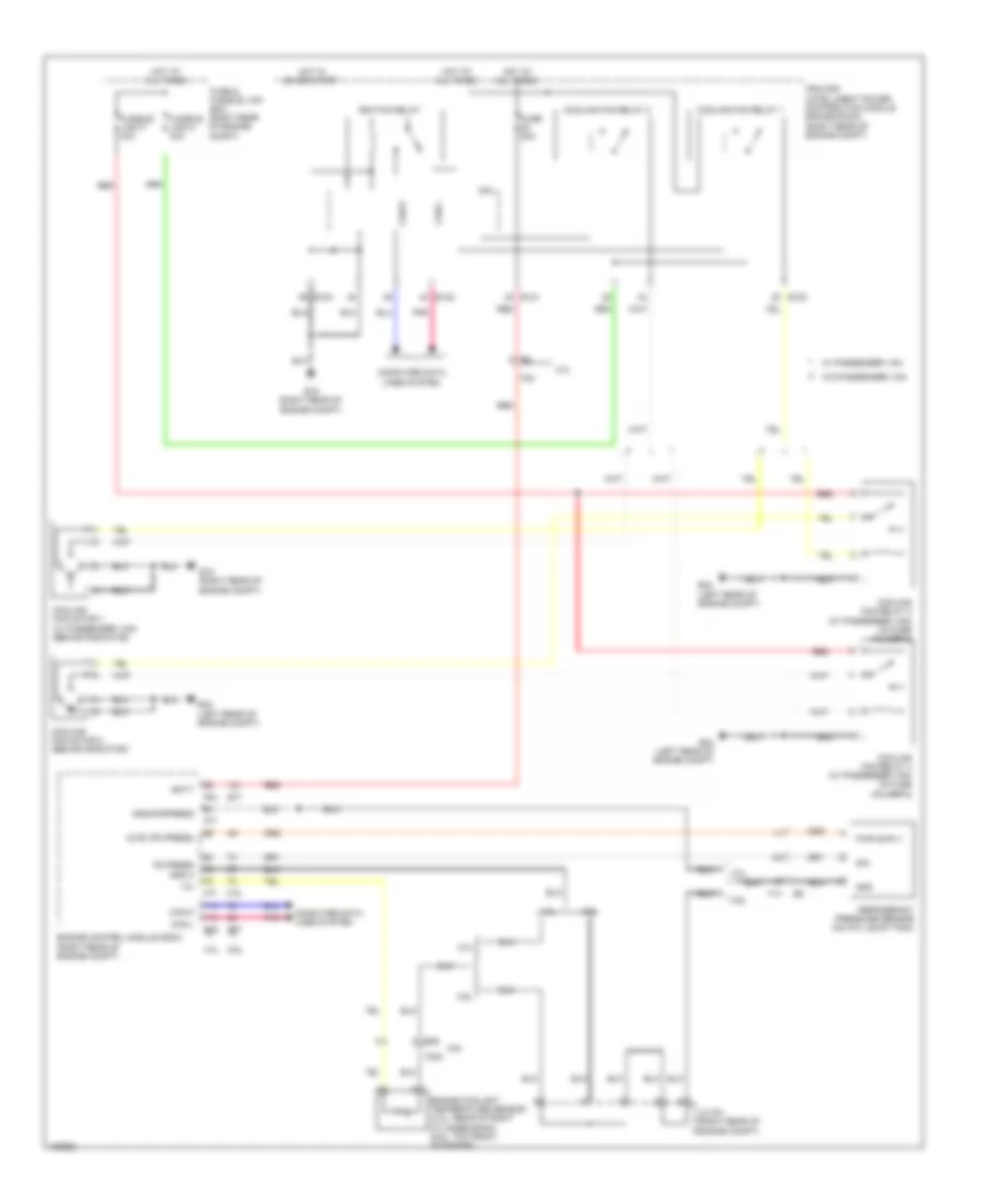
COOLING FAN
Cooling Fan Wiring Diagram for Nissan NVHD SL 2014 3500
List of elements for Cooling Fan Wiring Diagram for Nissan NVHD SL 2014 3500:
- 4.0l
- 5.6l
- Avcc (pd press)
- Batt
- Can-h
- Can-l
- Computer data lines system
- Cooling fan motor 1 (w/ passenger van) (behind radiator)
- Cooling fan motor 2 (behind radiator)
- Cooling fan relay 1
- Cooling fan relay 2
- Cooling fan relay 3 (w/ passenger van) (in fuse holder-2)
- Cooling fan relay 4 (w/ passenger van) (in fuse holder-2)
- Cpu
- E120
- E121
- E122
- E124
- E15 (right rear of engine compt)
- E16
- E24 (left rear of engine compt)
- E77
- Engine control module (ecm) (right rear of engine compt)
- Engine coolant temperature sensor (4.ol: rear of right cylinder bank) (5.6l: top front of engine)
- F14
- F203
- F32
- F36
- F54
- F72
- F77
- Fuse & fusible link box (right rear of engine compt)
- Fuse 20a
- Fusible link m 40a
- Fusible link p 40a
- Gnd
- Gnd a
- Gnda-pdpress
- Hot at all times
- Hot in on or start
- Ignition relay
- Ipdm e/r (intelligent power distribution module engine room) (right rear of engine compt)
- J/c f01 (right rear of engine compt)
- Pd press
- Pnk
- Pwr suply
- Red
- Refrigerant pressure sensor (on a/c liquid tank)
- Sig
- W/ passenger van
- W/o passenger van
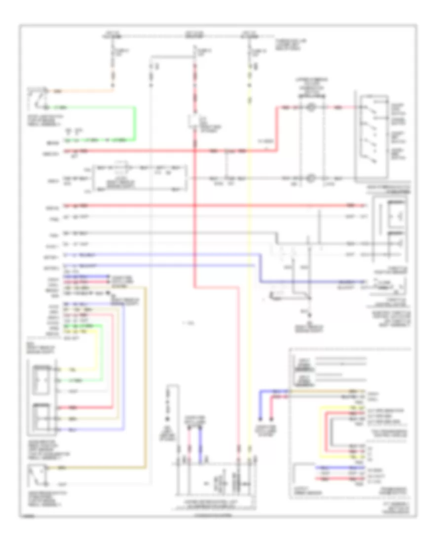
CRUISE CONTROL
Cruise Control Wiring Diagram for Nissan NVHD SL 2014 3500
List of elements for Cruise Control Wiring Diagram for Nissan NVHD SL 2014 3500:
- (upper steering column) combination switch (spiral cable)
- (w/ ascd) cruise ind
- (w/ ascd) set ind
- 13g
- 14g
- 4.0l
- 5.6l
- A/t assembly (bottom of transmission)
- Accel/ res switch
- Accelerator pedal position (app) sensor (top of accelerator pedal assembly)
- Aps1
- Aps2
- Ascd brake switch (if equipped) (top of brake pedal assembly)
- Ascd steering switch (if equipped)
- Ascd sw
- Avcc
- Avcc 1
- Avcc2
- Bncsw
- Brake
- C1 (vin)
- C2 (vout)
- C3 (gnd)
- Can-h
- Can-l
- Cancel switch
- Close
- Coast/ set switch
- Combination meter
- Computer data lines system
- E152
- E16
- E51
- E77
- E9 (right rear of engine compt)
- Ecm (right rear of engine compt)
- Electric throttle control actuator (on throttle body assembly)
- F14
- F502
- F503
- F505
- F506
- F54
- F72
- Fuse 12 10a
- Fuse 19 10a
- Fuse 21 10a
- Fuse block (j/b) (lower left end of dash)
- Gnd
- Gnd-a
- Gnd-a2
- Hot at all times
- Hot in on or start
- Input speed sensor 1
- Input speed sensor 2
- J/c f01 (right rear of engine compt)
- J/c m04 (right end of dash)
- M102
- M23
- M24
- M30
- M31
- M39
- M61 (left center of dash)
- Motor 1
- Motor 2
- Nca
- On/off main switch
- Open
- Out spd sen
- Out spd sen gnd
- Out spd sens pwr
- Output speed sensor
- Pnk
- Red
- Sensor 1
- Sensor 2
- Stop lamp switch (top of brake pedal assembly)
- Tcm (transmission control module)
- Throttle control motor
- Throttle position sensor
- Tps1
- Tps2
- Transmission range switch
- Unified meter control unit (w/ information display)
- W/ ascd
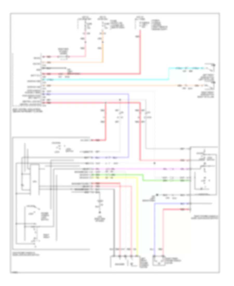
DEFOGGERS
Defoggers Wiring Diagram for Nissan NVHD SL 2014 3500
List of elements for Defoggers Wiring Diagram for Nissan NVHD SL 2014 3500:
- +ig
- 3g m31
- 91g
- Automatic a/c
- Bat
- Bat (f/l)
- Bcm (body control module) (behind instrument cluster)
- Can-h
- Can-l
- Computer data lines system
- Cpu
- D102
- D401
- D402
- D425
- D426
- D427
- D605
- D606
- D625
- D626
- D627
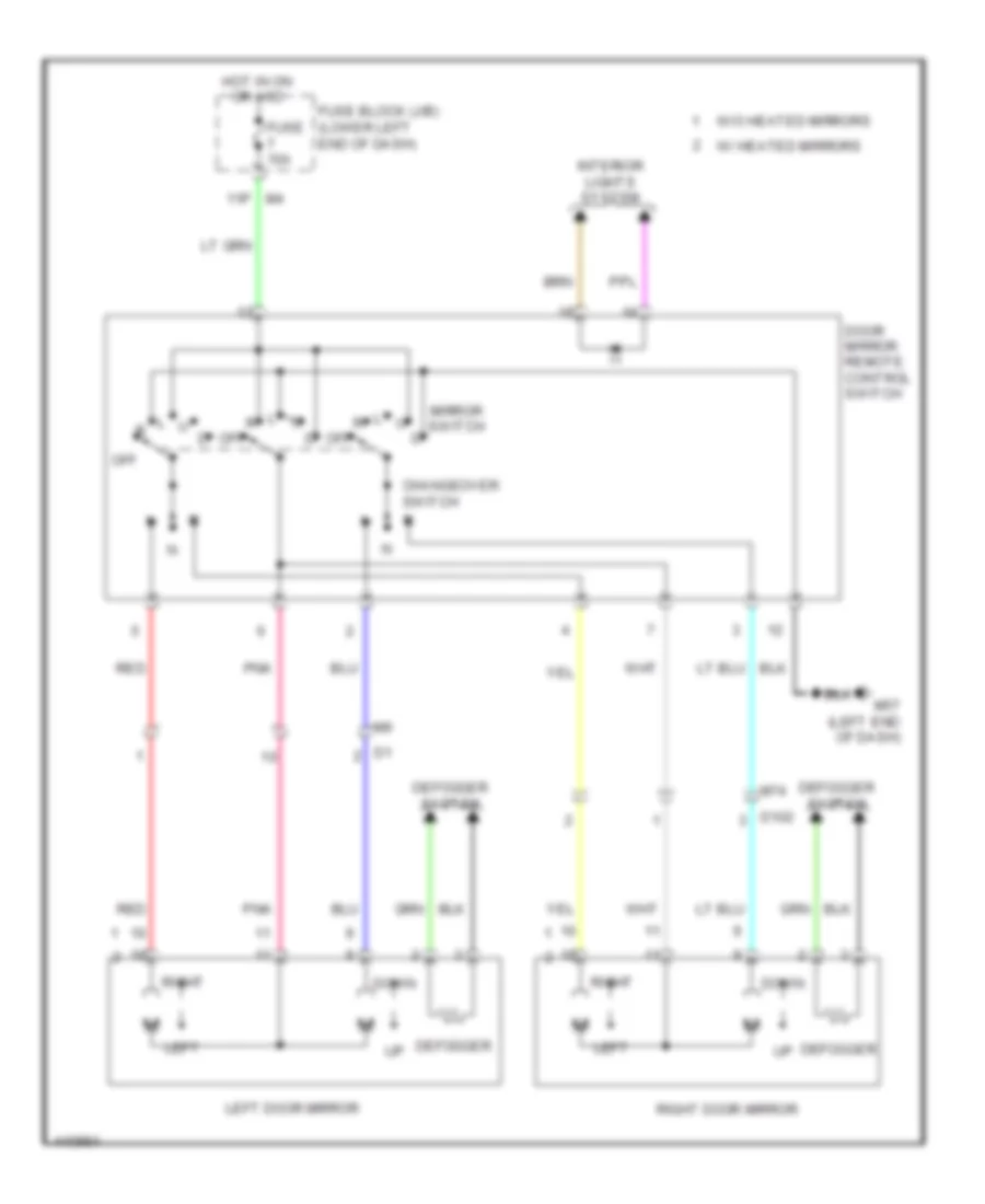
- Door mirror defogger
- E120
- E122
- E124
- E15 (right rear of engine compt)
- E152
- E52
- Front air control
- Fuse & fusible link box (right rear of engine compt)
- Fuse 10a
- Fuse 15a
- Fuse block (j/b) (lower left end of dash)
- Fusible link j 40a
- Gnd
- Gnd (sig)
- Heated mirror relay (if equipped)
- Hot at all times
- Hot in on or start
- Ign
- Ign sw
- Ignition relay
- Ipdm e/r (intelligent power distribution module engine room) (right rear of engine compt)
- J/c-m04 (right end of dash)
- Left door mirror
- Left rear window defogger
- M18
- M20
- M31
- M39
- M49
- M53
- M57 (left end of dash)
- M74
- M79 (right end of dash)
- Manual a/c
- Pnk
- Pwr gnd
- R13 (left "d" pillar)
- R14
- R23
- R24
- Rear window defogger relay
- Red
- Right door mirror
- Right rear window defogger
- Rr def
- Rr def on
- Rr def sw
ENGINE PERFORMANCE
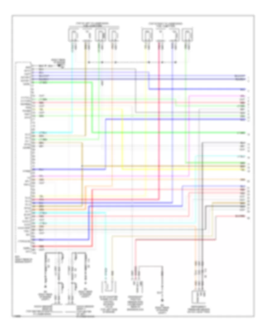
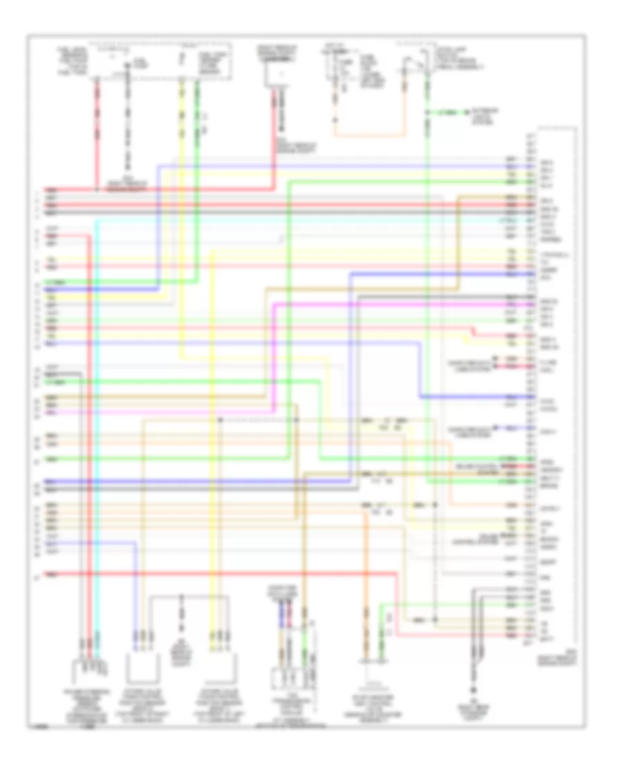
4.0L
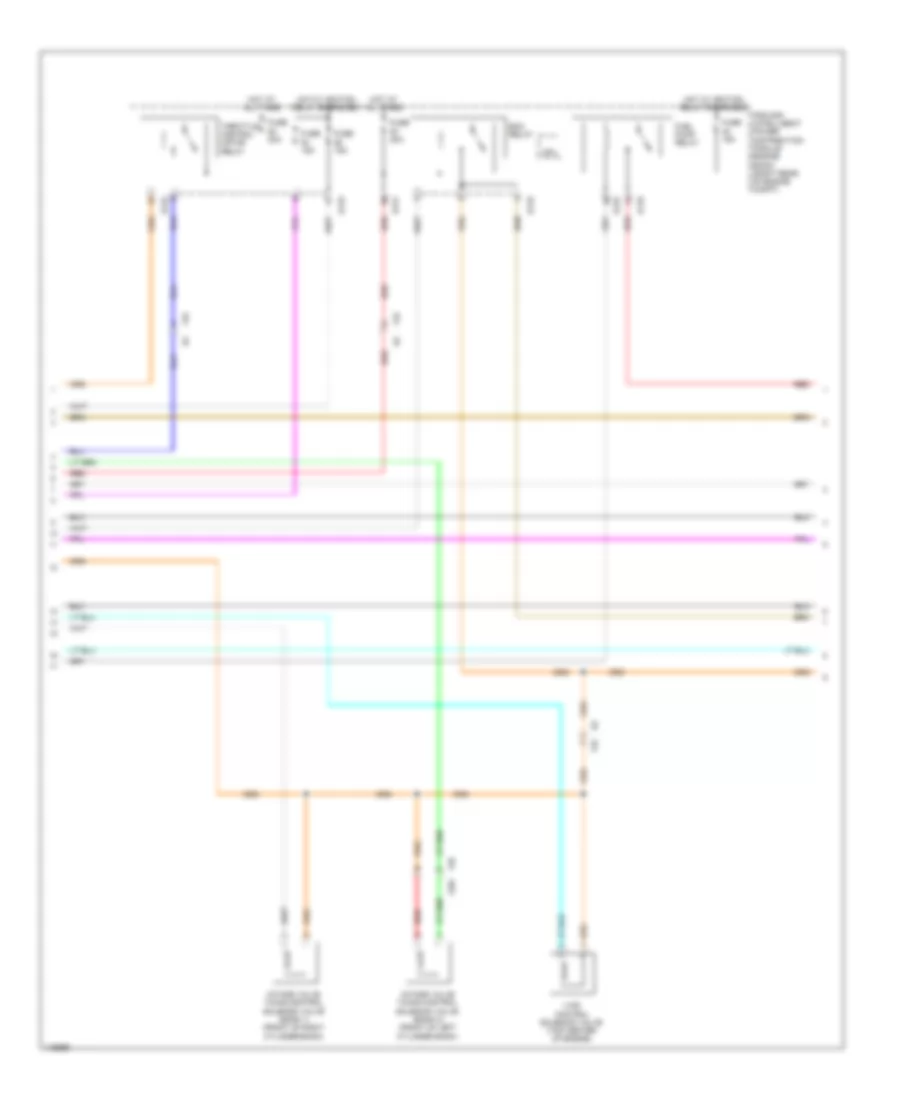
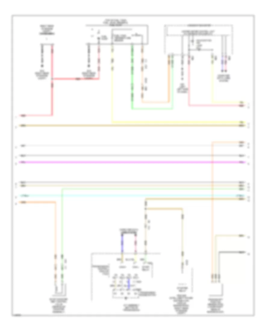
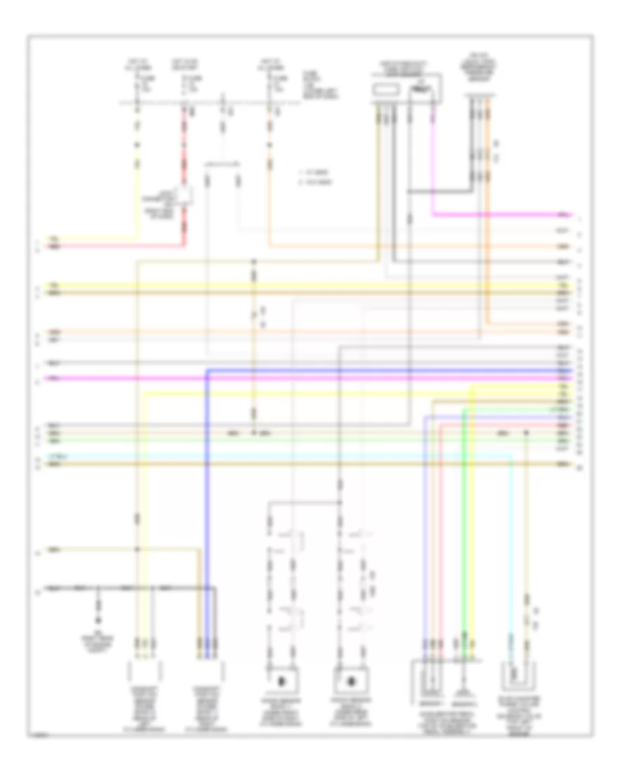
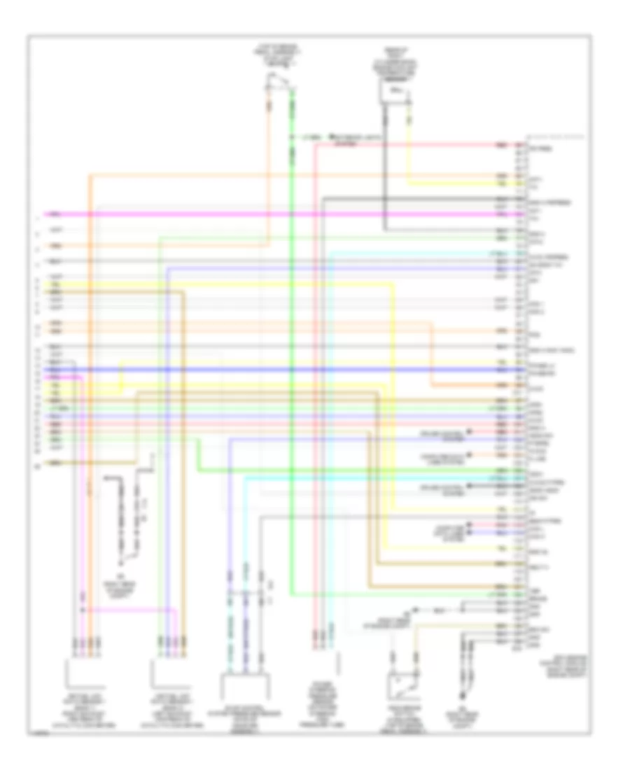
4.0L, Engine Performance Wiring Diagram (1 of 6) for Nissan NVHD SL 2014 3500
List of elements for 4.0L, Engine Performance Wiring Diagram (1 of 6) for Nissan NVHD SL 2014 3500:
- Af-h1
- Af-h2
- Avcc1 tps
- Batt
- C-vtc l
- C-vtc r
- Close
- E9 (right rear of engine compt)
- Ecm (engine control module) (right rear of engine compt)
- Electric throttle control actuator (on throttle body assembly)
- Evap
- F14
- F32
- F54
- F77
- Fpr
- Gnd
- Gnd a
- Gnd a pdpres
- Gnd a tps
- Heated oxygen sensor 2 (bank 1) (right exhaust, downstream of catalytic converter)
- Heated oxygen sensor 2 (bank 2) (left exhaust, downstream of catalytic converter)
- Ign 1
- Ign 2
- Ign 3
- Ign 4
- Ign 5
- Ign 6
- Inj 1
- Inj 2
- Inj 3
- Inj 4
- Inj 5
- Inj 6
- Mot rly
- Mtr 1
- Mtr 2
- Nca
- O2 hrl
- O2 hrr
- O2 srl
- O2 srr
- Open
- Pdpress
- Pnk
- Red
- Sensor 1
- Sensor 2
- Ssoff
- Throttle control motor
- Throttle position sensor
- Tps 1
- Tps 2
- V mot
- Vias
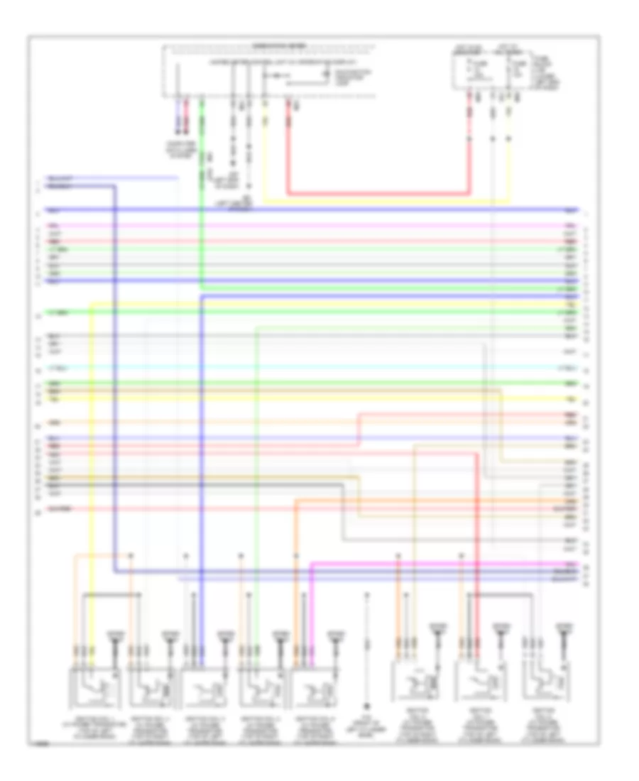
4.0L, Engine Performance Wiring Diagram (2 of 6) for Nissan NVHD SL 2014 3500
List of elements for 4.0L, Engine Performance Wiring Diagram (2 of 6) for Nissan NVHD SL 2014 3500:
- (top center rear of engine) condenser 1
- F16 (front of left cylinder bank)
- F201
- F204 f37
- F26
- F32
- Fuel injector 1, 3 & 5 (top of right cylinder bank)
- Fuel injectors 2, 4 & 6 (top of left cylinder bank)
- Ignition coil 1 (w/ power transistor) (top of right cylinder bank)
- Ignition coil 2 (w/ power transistor) (top of left cylinder bank)
- Ignition coil 3 (w/ power transistor) (top of right cylinder bank)
- Ignition coil 4 (w/ power transistor) (top of left cylinder bank)
- Ignition coil 5 (w/ power transistor) (top of right cylinder bank)
- Ignition coil 6 (w/ power transistor) (top of left cylinder bank)
- Nca
- Pnk
- Red
- Spark plug
4.0L, Engine Performance Wiring Diagram (3 of 6) for Nissan NVHD SL 2014 3500
List of elements for 4.0L, Engine Performance Wiring Diagram (3 of 6) for Nissan NVHD SL 2014 3500:
- Cpu
- E119
- E121
- E122
- Ecm relay
- F201
- F26
- F32
- Fuel pump relay
- Fuse 15a
- Fuse 20a
- Hot at all times
- Hot w/ ignition relay energized
- Intake valve timing control solenoid valve (bank 1) (front of right cylinder bank)
- Intake valve timing control solenoid valve (bank 2) (front of left cylinder bank)
- Ipdm e/r (intelligent power distribution module engine room) (right rear of engine compt)
- Red
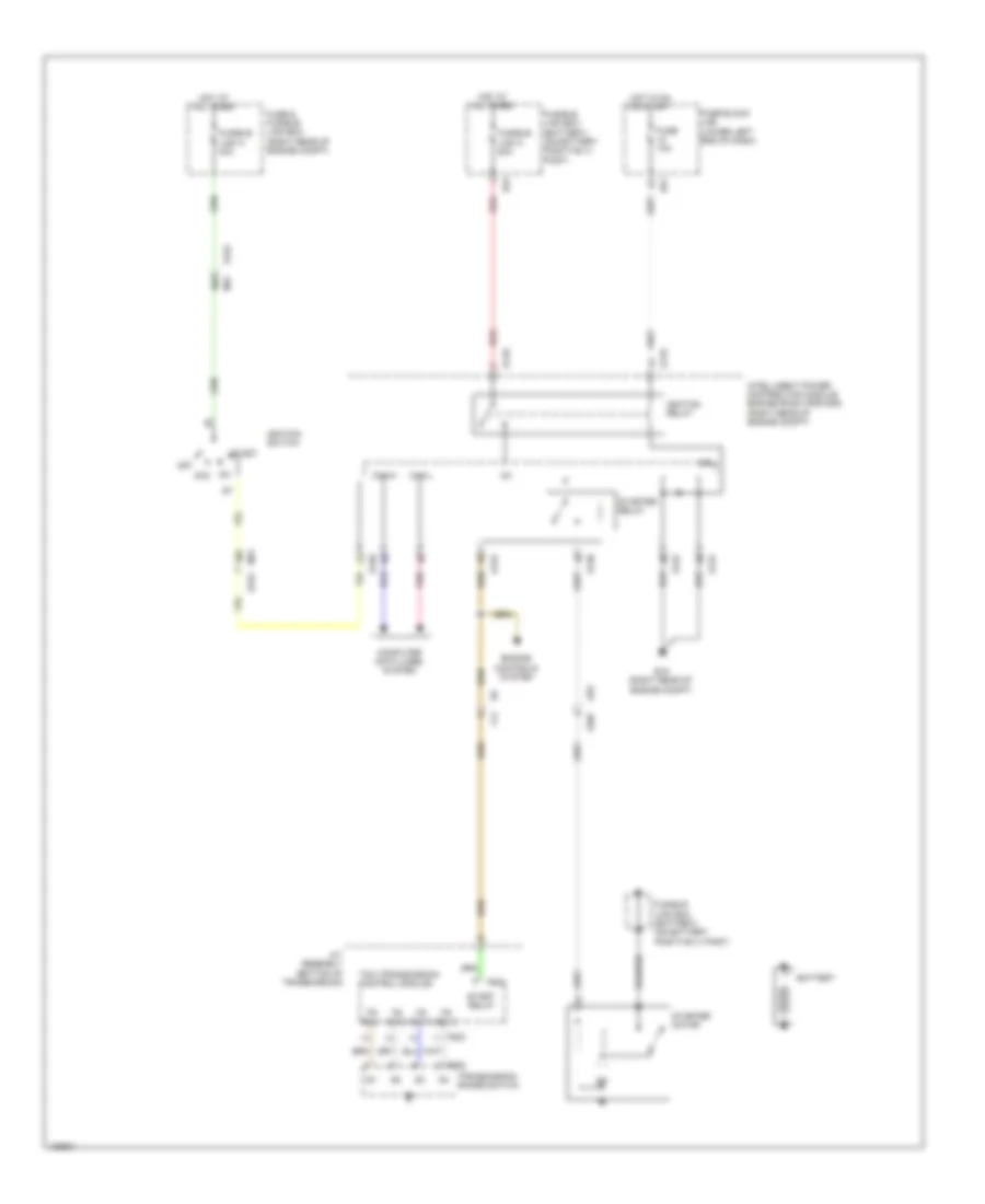
- Throttle control motor relay
- Vias control solenoid valve (top center of engine)
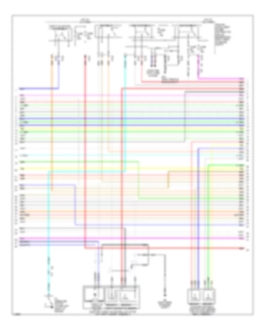
4.0L, Engine Performance Wiring Diagram (4 of 6) for Nissan NVHD SL 2014 3500
List of elements for 4.0L, Engine Performance Wiring Diagram (4 of 6) for Nissan NVHD SL 2014 3500:
- (right rear of engine compt) condenser 2
- (top of fuel tank) fuel level sensor & fuel pump
- 17g
- 18g
- 20c
- 30c
- 31c
- 42c
- 44c
- 52c
- A/t assembly (bottom of transmission)
- Can-h
- Can-l
- Combination meter
- Computer data lines system
- Crankshaft position sensor (pos) (lower right rear of engine block)
- E122
- E15 (right rear of engine compt)
- E152
- E41
- Evap canister vent control valve (near evap canister assembly)
- F14
- F502
- F503
- F505
- Fuel pump
- Fuel tank temperature sensor
- Ipdm e/r (intelligent power distribution module engine room) (right rear of engine compt)
- M23
- M24
- M31
- M57 (left left side of dash)
- Malfunction ind lamp (mil)
- Pnk
- Red
- Start relay
- Starter relay
- Tr sw 1
- Tr sw 2
- Tr sw 3
- Tr sw 4
- Transmission control module (tcm)
- Transmission range switch
- Unified meter control unit (w/ information display)
4.0L, Engine Performance Wiring Diagram (5 of 6) for Nissan NVHD SL 2014 3500
List of elements for 4.0L, Engine Performance Wiring Diagram (5 of 6) for Nissan NVHD SL 2014 3500:
- (air intake duct) mass air flow (maf) sensor
- (on a/c liquid tank) refrigerant pressure sensor
- Accelerator pedal position sensor (top of accelerator pedal assembly)
- Camshaft position sensor (phase) (bank 1) (rear of right cylinder bank)
- Camshaft position sensor (phase) (bank 2) (rear of left cylinder bank)
- E51
- E9 (right rear of engine compt)
- Evap canister purge volume control solenoid valve (top left front of engine)
- F14
- F202
- F32
- F35
- Fuse 10a
- Fuse block (j/b) (lower left end of dash)
- Hot at all times
- Hot in on or start
- Iat sensor
- Joint connector m04 (right end of dash)
- Knock sensor (bank 1) (inner front side of right cylinder bank)
- Knock sensor (bank 2) (inner rear side of left cylinder bank)
- M39
- Red
- Sensor 1
- Sensor 2
- W/ ascd
- W/o ascd
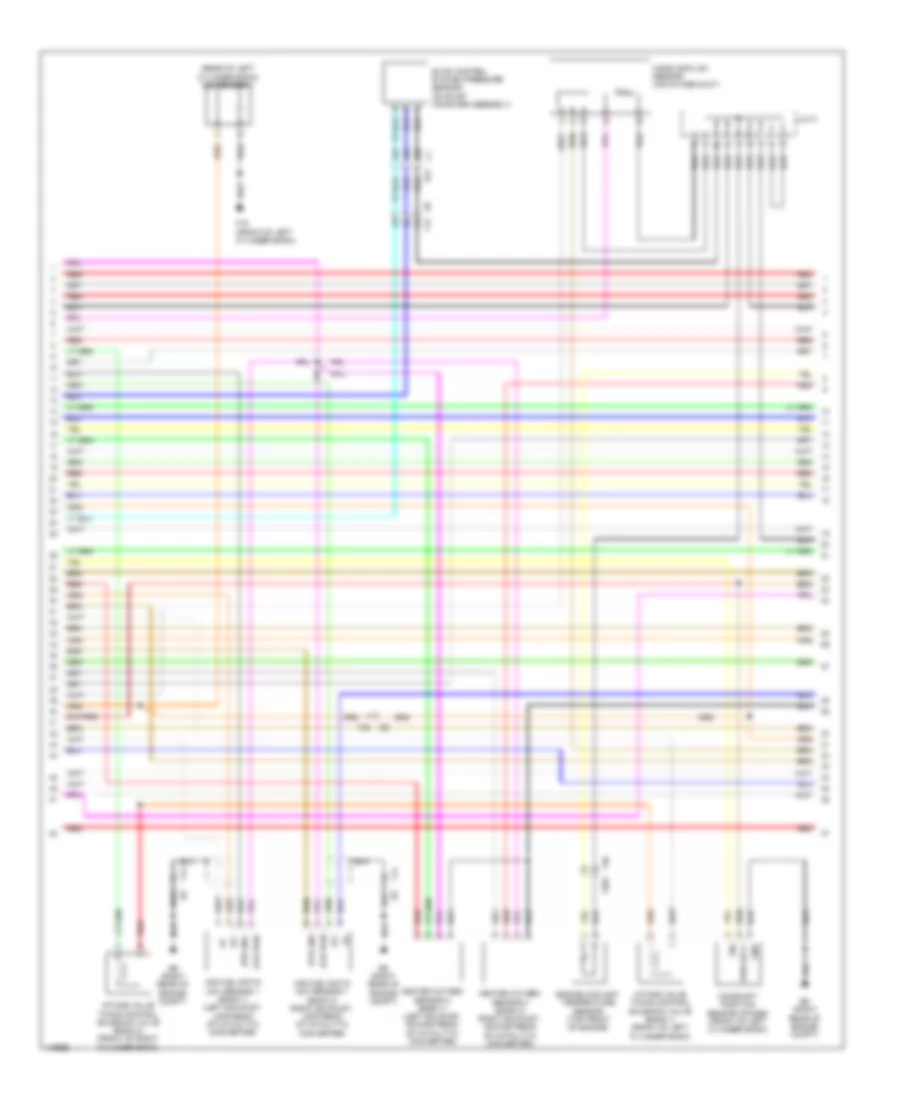
4.0L, Engine Performance Wiring Diagram (6 of 6) for Nissan NVHD SL 2014 3500
List of elements for 4.0L, Engine Performance Wiring Diagram (6 of 6) for Nissan NVHD SL 2014 3500:
- (rear of right cylinder bank) engine coolant temperature sensor
- (right rear of engine compt)
- (top of brake pedal assembly) stop lamp switch
- 45c
- 46c
- 47c
- A/f+1
- A/f+2
- A/f-1
- A/f-2
- Air fuel (a/f) ratio sensor 1 (bank 1) (right exhaust, upstream of catalytic converter)
- Air fuel (a/f) ratio sensor 1 (bank 2) (left exhaust, upstream of catalytic converter)
- Aps1
- Aps2
- Ascd brake switch (if equipped) (top of brake pedal assembly)
- Ascd sw
- Avcc
- Avcc (pspres)
- Avcc2
- Avcc2 ftprs
- Bnc sw
- Brake
- Can h
- Can l
- Cdcv
- Computer data lines system
- Cruise control system
- E16
- E41
- E9 (right rear of engine compt)
- Ecm (engine control module) (right rear of engine compt)
- Evap control system pressure sensor (on evap canister assembly)
- Exterior lights system
- F14
- F77
- Ft6prs
- Gnd
- Gnd a
- Gnd a knk1 knk2
- Gnd a pspress
- Gnd a2
- Gnda ascd
- Gnda ftprs
- Ign sw
- K line
- Knk 1
- Knk 2
- Neut h
- Phase lh
- Phase rh
- Pnk
- Pos
- Power steering pressure sensor (on power steering high- pressure tube)
- Ps pres
- Qa gnda ta1
- Qa+
- Red
- Ta1
- Vbr
5.6L
5.6L, Engine Performance Wiring Diagram (1 of 5) for Nissan NVHD SL 2014 3500
List of elements for 5.6L, Engine Performance Wiring Diagram (1 of 5) for Nissan NVHD SL 2014 3500:
- (right rear of engine compt)
- (top of left cylinder bank) fuel injectors
- (top of right cylinder bank) fuel injectors
- A/f+2
- A/f1
- Af+1
- Af-h1
- Af-h2
- Avcc
- Avcc (pdp)
- Avcc 2
- C-vtc(l)
- C-vtc(r)
- Crankshaft position sensor (pos) (lower right rear of engine block)
- E9 (right rear of engine compt)
- Ecm (right rear of engine compt)
- Evap
- Evap canister purge volume control solenoid valve (top left side of engine)
- F14
- F72
- Ftprs
- Gnd
- Ign 7
- Inj 1
- Inj 2
- Inj 3
- Inj 4
- Inj 5
- Inj 6
- Inj 7
- Knk 2
- Knk1
- Knock sensor (bank 1) (top center of left cylinder bank)
- Knock sensor (bank 2) (top center of right cylinder bank)
- Motor 1
- Motor 2
- Nca
- O2hrl
- O2hrr
- O2srl
- Phase
- Pnk
- Pos
- Ps-pres
- Pwr sply
- Pwr sup
- Qa+
- Red
- Refrigerant pressure sensor (on a/c liquid tank)
- Sig
- Tps 1
- Vmot
- Vtcpus (r)
5.6L, Engine Performance Wiring Diagram (2 of 5) for Nissan NVHD SL 2014 3500
List of elements for 5.6L, Engine Performance Wiring Diagram (2 of 5) for Nissan NVHD SL 2014 3500:
- 17g
- Combination meter
- Computer data lines system
- E152
- E51
- F16 (front of left cylinder bank)
- Fuse 10a
- Fuse block (j/b) (lower left end of dash)
- Hot at all times
- Hot in on or start
- Ignition coil 1 (w/ power transistor) (top of left cylinder bank)
- Ignition coil 2 (w/ power transistor) (top of right cylinder bank)
- Ignition coil 3 (w/ power transistor) (top of left cylinder bank)
- Ignition coil 4 (w/ power transistor) (top of right cylinder bank)
- Ignition coil 5 (w/ power transistor) (top of left cylinder bank)
- Ignition coil 6 (w/ power transistor) (top of right cylinder bank)
- Ignition coil 7 (w/ power transistor) (top of left cylinder bank)
- Ignition coil 8 (w/ power transistor) (top of right cylinder bank)
- M23
- M24
- M31
- M39
- M57 (left end of dash)
- M61 (left center of dash)
- Malfunction indicator lamp
- Nca
- Pnk
- Red
- Spark plug
- Unified meter control unit (w/ information display)
5.6L, Engine Performance Wiring Diagram (3 of 5) for Nissan NVHD SL 2014 3500
List of elements for 5.6L, Engine Performance Wiring Diagram (3 of 5) for Nissan NVHD SL 2014 3500:
- Accelerator pedal position (app) sensor (top of accelerator pedal assembly)
- Close
- Computer data lines system
- Cpu
- E119
- E121
- E122
- E124
- E15 (right rear of engine compt)
- E9 (right rear of engine compt)
- Ecm relay
- Electric throttle control actuator (on throttle body assembly)
- F14
- F32
- Fuel pump relay
- Fuse 15a
- Fuse 20a
- Hot at all times
- Ignition relay
- Ipdm e/r (intelligent power distribution module engine room) (right rear of engine compt)
- Nca
- Oil pressure switch (lower left front of engine)
- Open
- Pnk
- Red
- Sensor 1
- Sensor 2
- Throttle control motor
- Throttle control motor relay
- Throttle position sensor
5.6L, Engine Performance Wiring Diagram (4 of 5) for Nissan NVHD SL 2014 3500
List of elements for 5.6L, Engine Performance Wiring Diagram (4 of 5) for Nissan NVHD SL 2014 3500:
- (rear of left cylinder bank) condenser 1
- 45c
- 46c
- 47c
- Af+
- Af-
- Air fuel ratio (a/f) sensor 1 (bank 1) (left exhaust, upstream of catalytic converter)
- Air fuel ratio (a/f) sensor 1 (bank 2) (right exhaust, upstream of catalytic converter)
- Camshaft position sensor (phase) (front of left cylinder bank)
- E41
- E9 (right rear of engine compt)
- Engine coolant temperature sensor (top front of engine)
- Evap control system pressure sensor (on evap canister assembly)
- F14
- F16 (front of left cylinder bank)
- F203
- F32
- F36
- Gnd
- Heated oxygen sensor 2 (bank 1) (left exhaust, downstream of catalytic converter)
- Heated oxygen sensor 2 (bank 2) (right exhaust, downstream of catalytic converter)
- Htr gnd
- Htr pwr
- Intake valve timing control solenoid valve (bank 1) (front of left cylinder bank)
- Intake valve timing control solenoid valve (bank 2) (front of right cylinder bank)
- J/c f1
- Mass air flow sensor (air intake duct)
- Pwr sply
- Red
- Sig
5.6L, Engine Performance Wiring Diagram (5 of 5) for Nissan NVHD SL 2014 3500
List of elements for 5.6L, Engine Performance Wiring Diagram (5 of 5) for Nissan NVHD SL 2014 3500:
- (right rear of engine compt) condenser 2
- 30c
- 31c
- 42c
- 44c
- 48c
- 52c
- A/t assembly (bottom of transmission)
- Af-2
- Aps1
- Aps2
- Ascdsw
- Avcc
- Avcc2
- Batt
- Bncsw
- Brake
- C1 e41
- Can h
- Can l
- Cdcv
- Computer data lines system
- Cruise control system
- E15 (right rear of engine compt)
- E41
- E51
- E77
- E9 (right rear of engine compt)
- Ecm (right rear of engine compt)
- Evap canister vent control valve (near evap canister assembly)
- Exterior lights system
- F14
- F32
- F502 rly
- F72
- Fpr
- Fuel level sensor & fuel pump (top of fuel tank)
- Fuel pump
- Fuel tank temper- ature sensor
- Fuse 10a
- Fuse block (j/b) (lower left end of dash)
- Gnd
- Gnd 02
- Gnd a
- Gnd a2
- Hot at all times
- Ign 1
- Ign 2
- Ign 3
- Ign 4
- Ign 5
- Ign 6
- Ign 8
- Ignsw
- Inj 8
- Intake valve timing control position sensor (bank 1) (top front of left cylinder bank)
- Intake valve timing control position sensor (bank 2) (top front of right cylinder bank)
- K line
- Motrly
- Neut h
- O2srr
- Pdpres
- Pnk
- Power steering pressure sensor (on power steering pump high-pressure tube)
- Pwr
- Red
- Sig
- Sply
- Ssoff
- Stop lamp switch (top of brake pedal assembly)
- Tcm (transmission control module)
- Tps 2
- Vts pus (l)
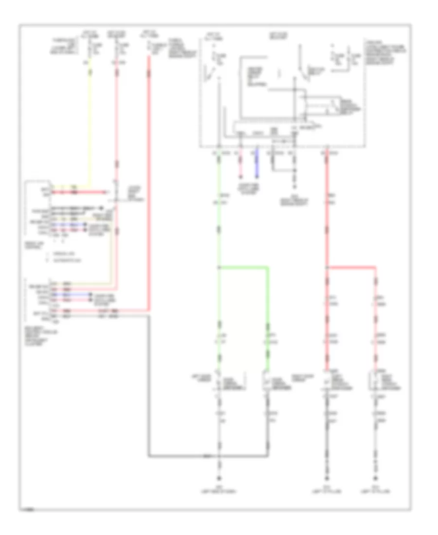
EXTERIOR LIGHTS
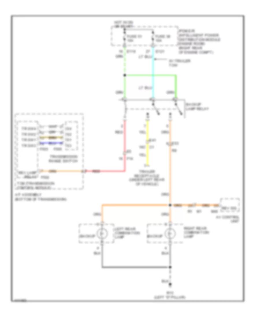
Backup Lamps Wiring Diagram for Nissan NVHD SL 2014 3500
List of elements for Backup Lamps Wiring Diagram for Nissan NVHD SL 2014 3500:
- (bottom of transmission)
- 16c c1
- A/t assembly
- Av control unit
- Backup
- Backup lamp relay
- E119
- E121
- E41
- E53
- F14
- F503
- F505
- Fuse 38 10a
- Fuse 51 10a
- Hot in on or start
- Ipdm e/r (intelligent power distribution module engine room) (right rear of engine compt)
- Left rear combination lamp
- M46
- R13 (left "d" pillar)
- Red
- Rev lamp relay f502
- Rev sig
- Right rear combination lamp
- Tcm (transmission control module)
- Tr sw1
- Tr sw2
- Tr sw3
- Tr sw4
- Trailer receptacle (under left rear of vehicle)
- Transmission range switch
- W/ trailer tow
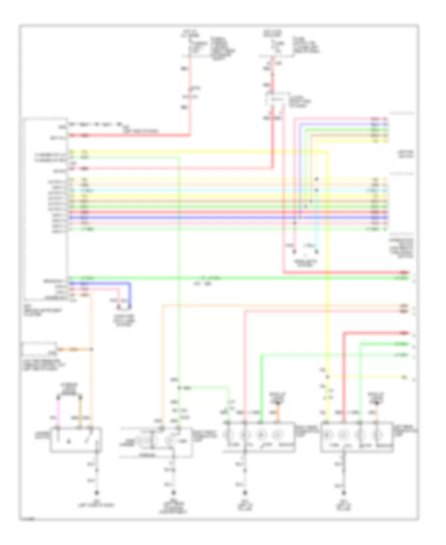
Exterior Lamps Wiring Diagram (1 of 2) for Nissan NVHD SL 2014 3500
List of elements for Exterior Lamps Wiring Diagram (1 of 2) for Nissan NVHD SL 2014 3500:
- 1q m39
- Back up lamps circuit
- Backup
- Bat (f/l)
- Bcm (behind instrument cluster)
- Brake sw 1
- Can-h
- Can-l
- Combination switch (high beam & turn signal switch)
- Computer data lines system
- E152
- E24 (left rear of engine compartment)
- E55
- Flasher o/p (lh)
- Flasher o/p (rh)
- Fuse & fusible link box (right rear of engine compt)
- Fuse 10a
- Fuse block (j/b) (lower left end of dash)
- Fusible link j 40a
- Gnd
- Haz
- Hazard sw
- Hazard switch
- Headlights system
- Hot at all times
- Hot in on or start
- Ign sw
- Input 1
- Input 2
- Input 3
- Input 4
- Input 5
- Interior lights system
- J/c m04 (right end of dash)
- Left rear combination lamp
- Lighting switch
- Low tire pressure warning control unit (left end of dash)
- M18
- M20
- M31
- M31 91g
- M57 (left end of dash)
- M61 (left side of dash)
- M78
- Output 1
- Output 2
- Output 3
- Output 4
- Output 5
- Parking
- Pnk
- R13 (left "d" pillar)
- Red
- Right front combination lamp
- Right rear combination lamp
- Side marker
- Stop
- Tail
- Turn
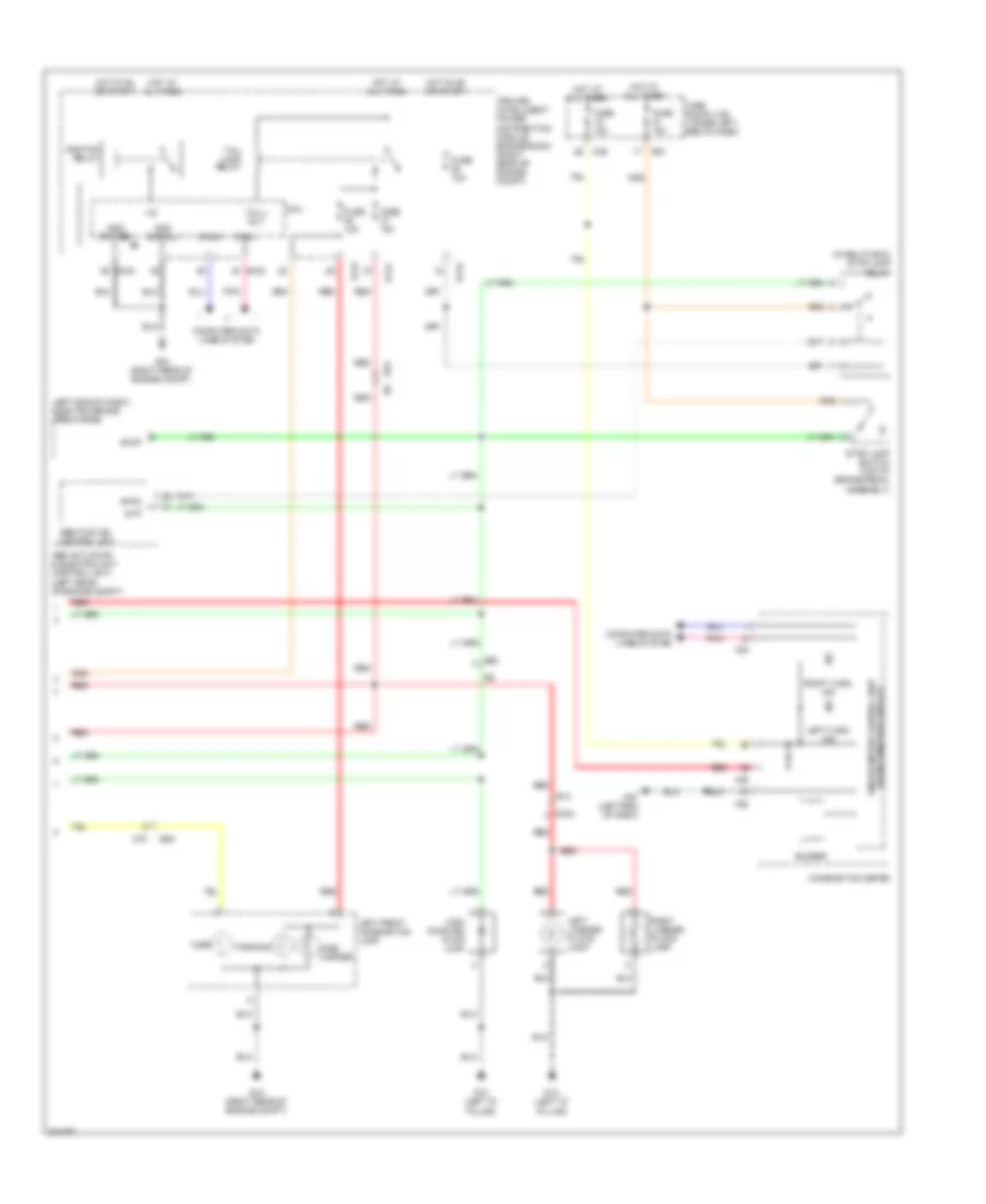
Exterior Lamps Wiring Diagram (2 of 2) for Nissan NVHD SL 2014 3500
List of elements for Exterior Lamps Wiring Diagram (2 of 2) for Nissan NVHD SL 2014 3500:
- (in relay box) stop lamp relay
- (left end of dash) electric brake (pre-wiring)
- (w/ information display) unified meter control unit
- +ig
- 1t e51
- 4q m39
- Abs actuator & electric unit (control unit) (left rear of engine compt)
- Abs/tcs/vdc control unit
- Buzzer
- Can-h
- Can-l
- Combination meter
- Computer data lines system
- Cpu
- D402
- E119
- E121
- E122
- E124
- E15 (right rear of engine compt)
- E53
- E55
- Fuse 10a
- Fuse block (j/b) (lower left end of dash)
- Gnd (power)
- Gnd (signal)
- High mounted stop lamp
- Hot at all times
- Hot in on or start
- Hot in or or start
- Ignition relay
- Ipdm e/r (intelligent power distribution module engine room) (right rear of engine compt)
- Left front combination lamp
- Left license plate lamp
- Left turn ind
- M23
- M24
- M57 (left end of dash)
- M78
- Parking
- Pnk
- R13 (left "d" pillar)
- R14
- Red
- Right license plate lamp
- Right turn ind
- Side marker
- Stop
- Stop lamp switch (top of brake pedal assembly)
- Stp
- Stpo
- Tail lamp relay
- Tail/l rly
- Turn
Trailer Tow Wiring Diagram for Nissan NVHD SL 2014 3500
List of elements for Trailer Tow Wiring Diagram for Nissan NVHD SL 2014 3500:
- (top of brake pedal assembly) stop lamp switch
- (under left rear of vehicle)
- (w/ information
- +ig
- 11c
- 16c
- 1q m4
- 24g
- 25g
- 51c
- Abs actuator & electric unit (control unit) (left rear of engine compt)
- Abs/tcs/vdc control unit
- Backup lamps circuit
- Bat (f/l)
- Body control module (bcm) (behind instrument cluster)
- Brake
- Brk sw 1
- Can-h
- Can-l
- Combination meter
- Combination switch (high beam & turn signal switch)
- Computer data lines system
- Cpu
- Display)
- E119
- E122
- E124
- E15 (right rear of engine compt)
- E152
- E24 (left rear of engine compt)
- E41
- E51 1t
- E55
- Electric brake (pre-wiring) (left end of dash)
- Exterior lamps circuit
- Fuse & fusible link box (right rear of engine compt)
- Fuse 10a
- Fuse 15a
- Fuse block (j/b) (lower left end of dash)
- Fusible link g 30a
- Fusible link j 50a
- Fusible link k 30a
- Gnd
- Gnd (power)
- Gnd (pwr)
- Gnd (signal)
- Headlights lights system
- Hot at all times
- Hot in on or start
- Ign sw
- Ignition relay
- Input 1
- Input 2
- Input 3
- Input 4
- Input 5
- Ipdm e/r (intelligent power distribution module engine room) (right rear of engine compt)
- J/c mo4 (right end of dash)
- Left trailer turn relay (in relay box)
- Lighting switch
- M18
- M19
- M20
- M23
- M24
- M31
- M31 91g
- M57 (left end of dash)
- M78
- Output 1
- Output 2
- Output 3
- Output 4
- Output 5
- Pnk
- Red
- Right trailer turn relay (in relay box)
- Stop
- Stop lamp relay (in relay box)
- Stp
- Stpo
- Tail lamp relay
- Tail/l rly
- Trailer lh flash
- Trailer receptacle
- Trailer rh flash
- Trailer tow relay 1 (in relay box)
- Trailer tow relay 2 (in relay box)
- Unified meter control unit
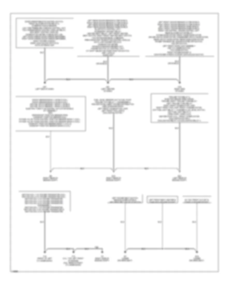
GROUND DISTRIBUTION
Ground Distribution Wiring Diagram (1 of 2) for Nissan NVHD SL 2014 3500
List of elements for Ground Distribution Wiring Diagram (1 of 2) for Nissan NVHD SL 2014 3500:
- 5.6l
- Ac 120v front outlet & console power socket
- B19 (under driver's seat)
- B7 (under driver's seat)
- Door mirror remote control switch, front blower motor relay-2, steering angle sensor, low tire pressure warning control unit, tcm (transmission control module) relay, bcm (body control module), combination meter, fuse block (j/b), left door mirror (door mirror defogger), right door mirror (door mirror defogger), right power window, door lock/unlock switch & nats antenna amp
- E15 (right rear of engine compt)
- E24 (left rear of engine compt)
- E9 (right rear of engine compt)
- F10 (4.0l: top left front of engine) (5.6l: rear of right cylinder bank)
- F16 (front of left cylinder bank)
- F2 (right side of engine compt)
- Fuel level sensor unit & fuel pump, trailer tow relay 1, condenser 2, ipdm e/r (intelligent power distribution module engine room), left front combination lamp, left front fog lamp & cooling fan motor 1
- Ignition coil 7 (w/ power transistor) (5.6l), ignition coil 8 (w/ power transistor) (5.6l), ignition coil 2 (w/ power transistor), ignition coil 4 (w/ power transistor), ignition coil 6 (w/ power transistor), condenser 1, ignition coil 1 (w/ power transistor), ignition coil 3 (w/ power transistor) & ignition coil 5 (w/ power transistor)
- Knock sensor (bank 1) shield (5.6l), knock sensor (bank 2) shield (5.6l), air fuel ratio sensor 1 (bank 1) shield, air fuel ratio sensor 1 (bank 2) shield, electric throttle control actuator shield, a/t assembly, ecm, crankshaft position sensor (pos), camshaft position sensor (5.6l), intake valve timing control position sensor (bank 1) (5.6l), intake valve timing control position sensor (bank 2) (5.6l), camshaft position sensor (bank 1) (4.0l) & camshaft position sensor (bank 2) (4.0l)
- Left front seat heater & third row power socket
- Left front sonar sensor outer shield, right front sonar sensor outer shield, left front sonar sensor inner shield, right front sonar sensor inner shield, front air control, sonar control unit, rear blower motor relay, intake door motor, front mode door motor, driver air mix door motor, passenger air mix door motor, rear air mix door motor, rear mode door motor, power transistor, sonar system off switch, vdc off switch, left front door lock assembly (key cylinder switch), tow mode switch, front power socket & main power window & door lock/unlock switch
- Left power seat switch, rear blower motor & left seat belt buckle switch
- M57 (left end of dash)
- M61 (left center of dash)
- M79 (right end of dash)
- Trailer tow relay 2, electric brake (pre-wiring), trailer, right trailer turn relay, left trailer turn relay, right front combination lamp, right front fog lamp, front washer motor, daytime light relay 1, washer fluid level switch, daytime light relay 2, horn (high), horn (low), heater pump (4.0l) , front wiper motor, cooling fan motor 2, cooling fan relay 3 & cooling fan relay 4
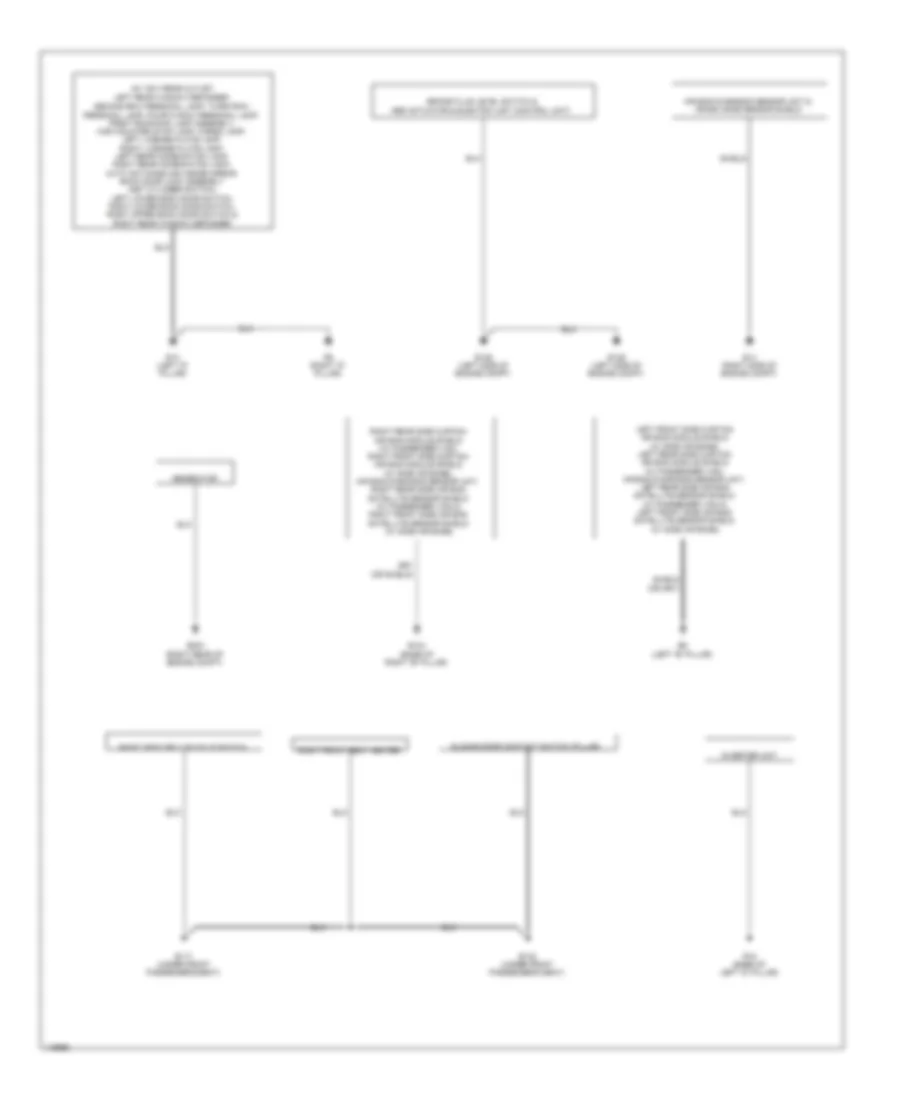
Ground Distribution Wiring Diagram (2 of 2) for Nissan NVHD SL 2014 3500
List of elements for Ground Distribution Wiring Diagram (2 of 2) for Nissan NVHD SL 2014 3500:
- Ac 120v rear outlet,
- Air bag diagnosis sensor unit & crash zone sensor shield
- B104 (base of right "b" pillar)
- B117 (under front passenger's seat)
- B132 (under front passenger's seat)
- B5 (left "b" pillar)
- Brake fluid level switch & abs actuator & electric unit (control unit)
- E126 (left side of engine compt)
- E129 (left side of engine compt)
- E14 (right side of engine compt)
- E203 (right rear of engine compt)
- Generator
- Inverter unit
- Left front side curtain air bag module shield (w/ side air bags), left rear side curtain air bag module shield (w/ passenger van), air bag diagnosis sensor unit, left rear side air bag satellite sensor shield (w/ passenger van) & left front side air bag satellite sensor shield (w/ side air bags)
- Left rear window defogger,
- R13 (left "d" pillar)
- R15 (base of left "d" pillar)
- R8 (right "d" pillar)
- Right front seat heater
- Right rear side curtain air bag module shield (w/ passenger van), right front side curtain air bag module shield (w/ side air bags), air bag diagnosis sensor unit, right rear side air bag satellite sensor shield (w/ passenger van) & right front side air bag satellite sensor shield (w/ side air bags)
- Right seat belt buckle switch
- Second row personal lamp, third row personal lamp, fourth row personal lamp, front room/map lamp assembly, high mounted stop lamp, cargo lamp, left license plate lamp, right license plate lamp, left rear combination lamp, right rear combination lamp, auto anti-dazzling inside mirror, back door lock assembly (key cylinder switch), left lower back door switch, right lower back door switch, right upper back door switch & right rear window defogger
- Shield
- Sliding door contact switch (pillar)
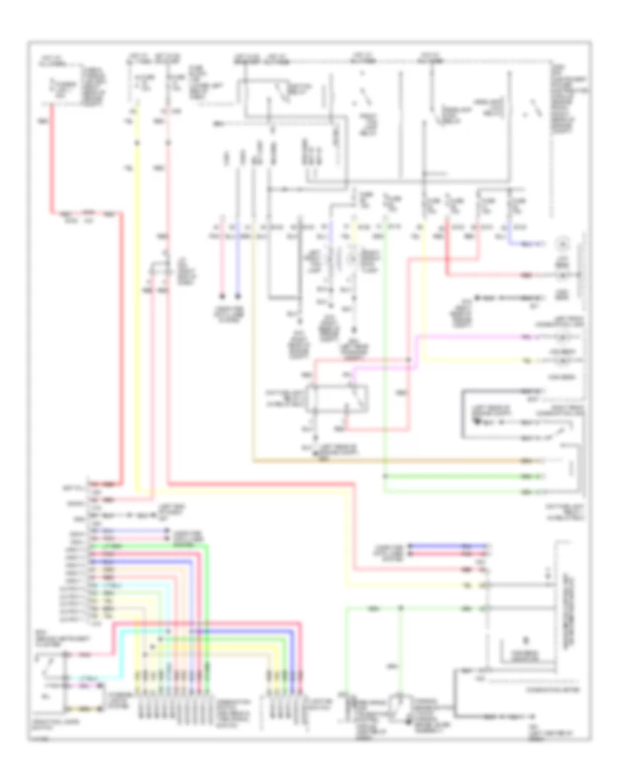
HEADLIGHTS
Headlights Wiring Diagram, Canada for Nissan NVHD SL 2014 3500
List of elements for Headlights Wiring Diagram, Canada for Nissan NVHD SL 2014 3500:
- (left end of dash) m57
- (left rear of engine compt) e24
- (lower left end of dash)
- (right rear of engine compt)
- +ig
- 91g
- Bat (f/l)
- Bcm (behind instrument cluster)
- Brk parking
- Can-h
- Can-l
- Combination meter
- Combination switch (high beam & turn signal switch)
- Computer data lines system
- Cpu
- Daytime light relay 1 (in relay box)
- Daytime light relay 2 (in relay box)
- Drl rly cont
- E107
- E11
- E119
- E121
- E122
- E123
- E124
- E15
- E15 (right rear of engine compt)
- E152
- E24 (left rear of engine compt)
- Fr fog
- Front fog lamp relay
- Front fog lamps switch
- Fuse & fusible link box (right rear of engine compt)
- Fuse 10a
- Fuse 15a
- Fuse block (j/b)
- Fusible link j 40a
- Gnd
- H/lp hi
- H/lp lo
- Headlamp high relay
- Headlamp low relay
- High beam
- High beam indicator
- Hot at all times
- Hot in on or start
- Ign sw
- Ignition relay
- Input 1
- Input 2
- Input 3
- Input 4
- Input 5
- Interior lights system
- Ipdm e/r (instrument power distribution module engine room) (right rear of engine compt)
- J/c m04 (right end of dash)
- Left front combination lamp
- Left front fog lamp
- Lighting switch
- Low beam
- M18
- M20
- M23
- M24
- M31
- M39
- M61 (left center of dash)
- Output 1
- Output 2
- Output 3
- Output 4
- Output 5
- Parking brake switch (top of parking brake lever assembly)
- Pnk
- Pre-wiring for telematics control module (center of dash)
- Pwr (gnd)
- Red
- Right front combination lamp
- Right front fog lamp
- Sig (gnd)
- Unified meter control unit (w/ information display)
Headlights Wiring Diagram, USA for Nissan NVHD SL 2014 3500
List of elements for Headlights Wiring Diagram, USA for Nissan NVHD SL 2014 3500:
- (left end of dash) m57
- (left rear of engine compt) e24
- +ig
- 91g
- Bat (f/l)
- Bcm (behind instrument cluster)
- Brk parking
- Can-h
- Can-l
- Combination meter
- Computer data lines system
- Cpu
- Daytime light relay 1 (in relay box)
- Daytime light relay 2 (in relay box)
- Drl rly cont
- E119
- E122
- E123
- E124
- E15 (right rear of engine compt)
- E152
- E24 (left rear of engine compt)
- Fr fog
- Front fog lamp relay
- Front fog lamps switch
- Fuse & fusible link box (right rear of engine compt)
- Fuse 10a
- Fuse 15a
- Fuse block (j/b) (lower left end of dash)
- Fusible link j 40a
- Gnd
- H/lp hi
- H/lp lo
- Headlamp high relay
- Headlamp low relay
- High beam
- High beam indicator
- Hot at all times
- Hot in on or start
- Ign sw
- Ignition relay
- Input 1
- Input 2
- Input 3
- Input 4
- Input 5
- Interior lights system
- Ipdm e/r (intelligent power distribution module engine room) (right rear of engine compt)
- J/c m04 (right end of dash)
- Left front combination lamp
- Left front fog lamp
- Lighting switch
- Low beam
- M18
- M20
- M23
- M24
- M31
- M39
- M61 (left center of dash)
- Output 1
- Output 2
- Output 3
- Output 3 combination switch (high beam & turn signal switch)
- Output 4
- Output 5
- Parking brake switch (top of parking brake lever assembly)
- Pnk
- Pre-wiring for telematics control module (center of dash)
- Pwr (gnd)
- Red
- Right front combination lamp
- Right front fog lamp
- Sig (gnd)
- Unified meter control unit (w/ information display)
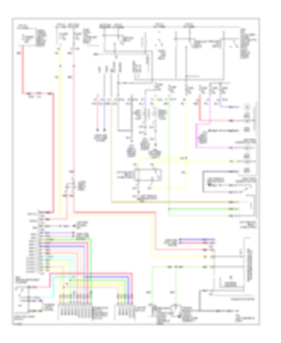
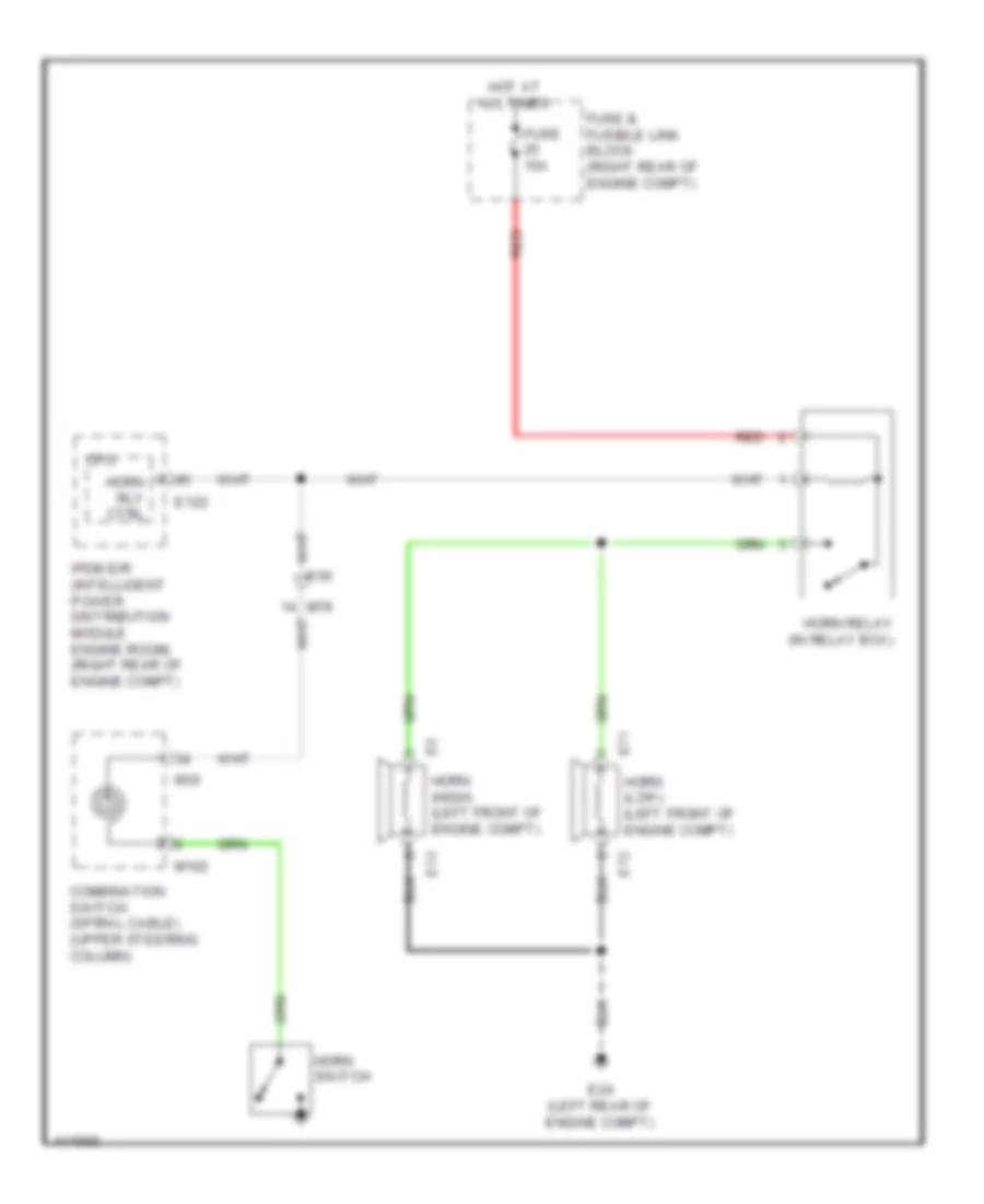
HORN
Horn Wiring Diagram for Nissan NVHD SL 2014 3500
List of elements for Horn Wiring Diagram for Nissan NVHD SL 2014 3500:
- Combination switch (spiral cable) (upper steering column)
- Cpu
- E122
- E13
- E24 (left rear of engine compt)
- E55
- E71
- E72
- Fuse & fusible link block (right rear of engine compt)
- Fuse 15a
- Horn (high) (left front of engine compt)
- Horn (low) (left front of engine compt)
- Horn relay (in relay box)
- Horn rly ctrl
- Horn switch
- Hot at all times
- Ipdm e/r (intelligent power distribution module engine room) (right rear of engine compt)
- M102
- M30
- M78
- Red
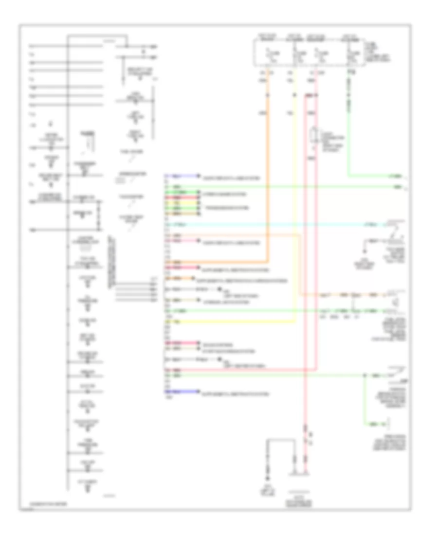
INSTRUMENT CLUSTER
Instrument Cluster Wiring Diagram (1 of 2) for Nissan NVHD SL 2014 3500
List of elements for Instrument Cluster Wiring Diagram (1 of 2) for Nissan NVHD SL 2014 3500:
- (if equipped)
- (w/ information display) unified meter control unit
- 17g
- 18g
- 20c
- 31c
- A/t check ind
- A/t oil temp ind
- Abs ind
- Air bag ind
- Auto anti-dazzling inside mirror
- Brake ind
- Buzzer
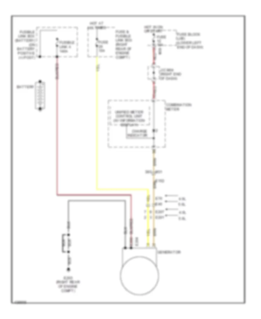
- Charge ind
- Combination meter
- Computer data lines system
- Cruise ind (w/ascd)
- Door ind
- Driver seat belt ind
- E41
- Fuel gauge
- Fuel level sensor unit & fuel pump (fuel level sensor) (top of fuel tank)
- Fuse 10a
- Fuse block (j/b) (lower left end of dash)
- High beam ind
- Hot at all times
- Hot in on or acc
- Hot in on or start
- Interior lights system
- Joint connector m04 (right end of dash)
- Left turn ind
- Low fuel ind
- M23
- M24
- M31 e152
- M39
- M57 (left end of dash)
- M61 (left center of dash)
- M79 (right end of dash)
- Malfunction ind lamp
- Master warning lamp
- Meter illumination ind
- Oil pressure ind
- Parking brake switch (top of parking brake lever assembly)
- Passenger belt ind
- Pnk
- Pre-wiring for telematics control module (center of dash)
- R13 (left "d" pillar)
- Red
- Right turn ind
- Security ind (if equipped)
- Set ind (w/ascd)
- Slip ind
- Sound systems
- Speedometer
- Starting/charging system
- Tachometer
- Tire pressure ind
- Tow ind
- Tow mode switch (w/ trailer tow 7 pin)
- Transmissions system
- Vdc off ind
- Washer ind (if equipped)
- Water temp gauge
- Wiper/washer system
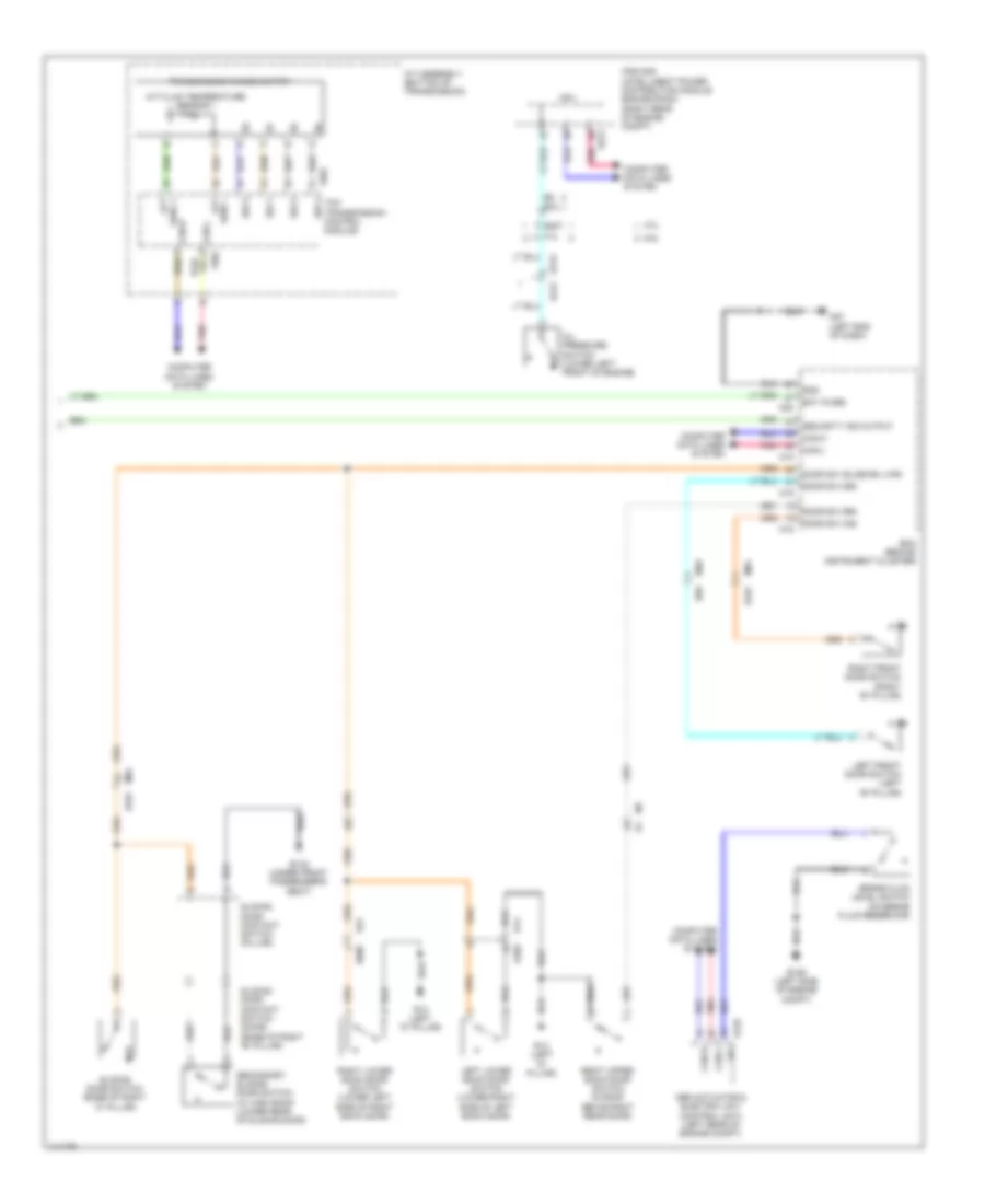
Instrument Cluster Wiring Diagram (2 of 2) for Nissan NVHD SL 2014 3500
List of elements for Instrument Cluster Wiring Diagram (2 of 2) for Nissan NVHD SL 2014 3500:
- 4.0l
- 5.6l
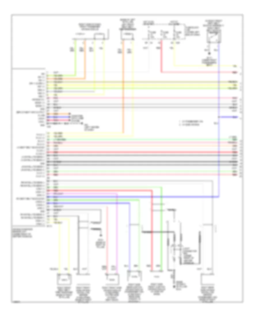
- A/t assembly (bottom of transmission)
- A/t fluid temperature sensor 1
- Abs actuator & electric unit (control unit) (left rear of engine compt)
- Aft sen1 -
- B101
- B132 (under front passenger's seat)
- B69
- Bat (fuse)
- Bcm (behind instrument cluster)
- Brake fluid level switch (on brake fluid reservoir)
- Can-h
- Can-l
- Computer data lines system
- Cpu
- D402
- D606
- Door sw (as)
- Door sw (dr)
- Door sw (rr)
- Door sw (slide bk lwr)
- E122
- E125
- E126 (left side of engine compt)
- E207
- E213 e212
- E5 e70
- F14
- F502
- F503
- Gnd
- Ipdm e/r (intelligent power distribution module engine room) (right rear of engine compt)
- Lbl
- Left front door switch (left "b" pillar)
- Left lower back door switch (lower right side of left back door)
- M18
- M19
- M20
- M40
- M57 (left end of dash)
- M84
- M84 b101
- Oil pressure switch (lower left front of engine)
- Pnk
- R13 (left "d" pillar)
- R14
- R24
- Right front door switch (right "b" pillar)
- Right lower back door switch (lower left side of right back door)
- Right upper back door switch (in roof above right rear door)
- Secondary sliding door switch (w/ high roof) (lower rear of sliding door)
- Security ind output
- Sen1 + aft
- Sliding door contact switch (door) (base of right "b" pillar)
- Sliding door contact switch (pillar)
- Sliding door switch (base of right "c" pillar)
- Sw 1
- Sw 2
- Sw 3
- Sw 4 tcm (transmission control module)
- Transmission range switch
INTERIOR LIGHTS
Courtesy Lamps Wiring Diagram (1 of 2) for Nissan NVHD SL 2014 3500
List of elements for Courtesy Lamps Wiring Diagram (1 of 2) for Nissan NVHD SL 2014 3500:
- (base of right "c" pillar) sliding door switch
- (left "d" pillar) r13
- (left end of dash) m57
- (right end of dash) m79
- (w/ power door locks)
- 91g
- B101
- B132 (under front passenger's seat)
- Back door lock assembly (key cylinder switch) (w/ power door locks)
- Battery (f/l)
- Battery (fuse)
- Battery saver output
- Body control module (behind instrument cluster)
- Can-h
- Can-l key cylinder lock sw
- Cargo van w/ 3 cargo lamps
- Cargo van w/ high roof
- Cargo van w/o high roof & passenger van
- Central door lock sw
- Central door unlock sw
- Computer data lines system
- D606
- Dome lamp (gnd)
- Door
- Door ajar (all)
- Door sw (as)
- Door sw (dr)
- Door sw (rr)
- E152
- Front room/ map lamp assembly
- Fuse & fusible link box (right rear of engine compt)
- Fuse 10a
- Fuse block (j/b) (lower left end of dash)
- Fusible link j 40a
- Gnd
- Hot at all times
- Hot in on or start
- Ign sw
- Joint connector m04 (right end of dash)
- Key cylinder unlock sw
- Key sw
- Key switch
- Left front door lock assembly (key cylinder switch)
- Lock
- M18
- M19
- M20
- M31
- M39
- M84
- Off
- Passenger van
- Passenger van w/ front step lamp
- Pnk
- Pre-wiring for telematics control module (center of dash)
- R13 (left "d" pillar)
- R2 m2
- R24
- Red
- Right front door switch (right "b" pillar)
- Right upper back door switch (above right rear door, in roof)
- Room lamp output
- Secondary sliding door switch (cargo van w/ high roof) (lower rear of sliding door)
- Slide/bk lwr door sw
- Sliding door contact switch (door) (base of right "b" pillar)
- Sliding door contact switch (pillar) (base of right "b" pillar)
- Sliding door lock assembly (key cylinder switch) (w/ power door locks)
- Step lamp output
- Unlock
- W/ power door locks
Courtesy Lamps Wiring Diagram (2 of 2) for Nissan NVHD SL 2014 3500
List of elements for Courtesy Lamps Wiring Diagram (2 of 2) for Nissan NVHD SL 2014 3500:
- (cargo van) center cargo lamp
- (cargo van) front cargo lamp
- (cargo van) rear cargo lamp
- (left end of dash) m57
- (right end of dash) m79
- B69
- Cargo lamp (passenger van)
- Cargo van w/ 3 cargo lamps
- Cpu n
- D101
- D102
- D402
- D606
- Door
- Fourth row personal lamp (passenger van)
- Gnd
- Left front door switch (left "b" pillar)
- Left front step lamp (passenger van)
- Left lower back door switch (lower right side of left back door)
- Lock
- M40
- M74
- M75
- Main power window & door lock/ unlock switch (w/ power door locks)
- Off
- Passenger van w/ second, third & fourth row personal lamps
- R101
- R13 (left "d" pillar)
- R14
- R24
- Red
- Right front step lamp (passenger van)
- Right lower back door switch (lower left side of right back door)
- Right power window & door lock/ unlock switch (w/ power door locks)
- Second row personal lamp (passenger van)
- Third row personal lamp (passenger van)
- Unlock
- W/ power door locks
Instrument Illumination Wiring Diagram (1 of 2) for Nissan NVHD SL 2014 3500
List of elements for Instrument Illumination Wiring Diagram (1 of 2) for Nissan NVHD SL 2014 3500:
- 91g
- Automatic a/c
- Bat (f/l)
- Batt
- Body control module (behind instrument cluster)
- Can-h
- Can-l
- Combination meter
- Combination switch (high beam & turn signal switch)
- Computer data lines system
- E152
- Fog lamp switch (if equipped)
- Front air control
- Fuse & fusible link box (right rear of engine compt)
- Fuse 10a
- Fuse block (j/b) (lower left end of dash)
- Fusible link j 40a
- Gnd
- Gnd (ill)
- Gnd (pwr)
- Headlights system
- Hot at all times
- Hot in on or start
- Ign sw
- Ill (+)
- Ill (-)
- Illu ctrl
- Input 1
- Input 2
- Input 3
- Input 4
- Input 5
- Joint connector m04 (right end of dash)
- Left front heated seat switch (if equipped)
- Lighting switch
- M18
- M20
- M23
- M24
- M31
- M39
- M49
- M53
- M57 (left end of dash)
- M61 (left center of dash)
- Manual a/c
- Meter illumination ind
- Output 1
- Output 2
- Output 3
- Output 4
- Output 5
- Pnk
- Rear air control (if equipped)
- Red
- Right front heated seat switch (if equipped)
- Run start
- Unified meter control unit (w/ information display)
Instrument Illumination Wiring Diagram (2 of 2) for Nissan NVHD SL 2014 3500
List of elements for Instrument Illumination Wiring Diagram (2 of 2) for Nissan NVHD SL 2014 3500:
- +ig
- A/c 120v outlet main switch (w/ inverter system)
- Ascd steering switch
- Audio unit (w/ base & mid audio systems)
- Av control unit (w/ premium audio system)
- Can-h
- Can-l
- Combination switch (spiral cable) (in steering column)
- Computer data lines system
- Cpu
- Door mirror remote control switch (w/ power outside mirrors)
- E122
- E123
- E124
- E15 (right rear of engine compt)
- E152
- Except base audio system
- Fuse 10a
- Gnd
- Gnd (power)
- Gnd (signal)
- Hazard switch
- Hot at all times
- Hot in on or start
- Ignition relay
- Ill (+)
- Ill (-)
- Ill cont sw (+)
- Ill cont sw (-)
- Ill+
- Ipdm e/r (intelligent power distribution module engine room) (right rear of engine compt)
- Joint connector m03 (left side of dash)
- M102
- M29
- M30
- M31
- M42
- M50
- M61 (left center of dash)
- Pnk
- Pre-wiring for telematics control module (center of dash)
- Sonar system off switch (if equipped)
- Steering wheel audio control switch
- Tail lamp relay
- Tail/l rly
- Tow mode switch (trailer tow 7 pin)
- Vdc off switch
- W/ ascd
- W/ base audio system
- W/ mid audio system
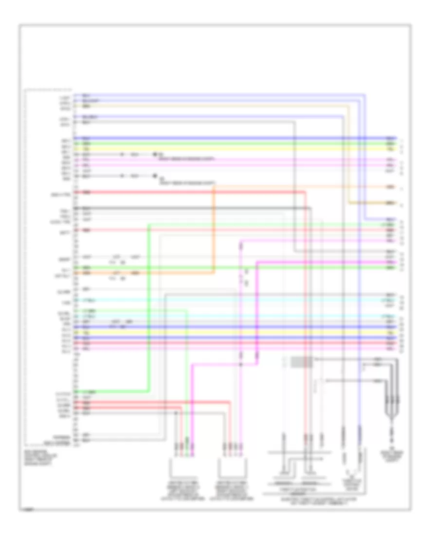
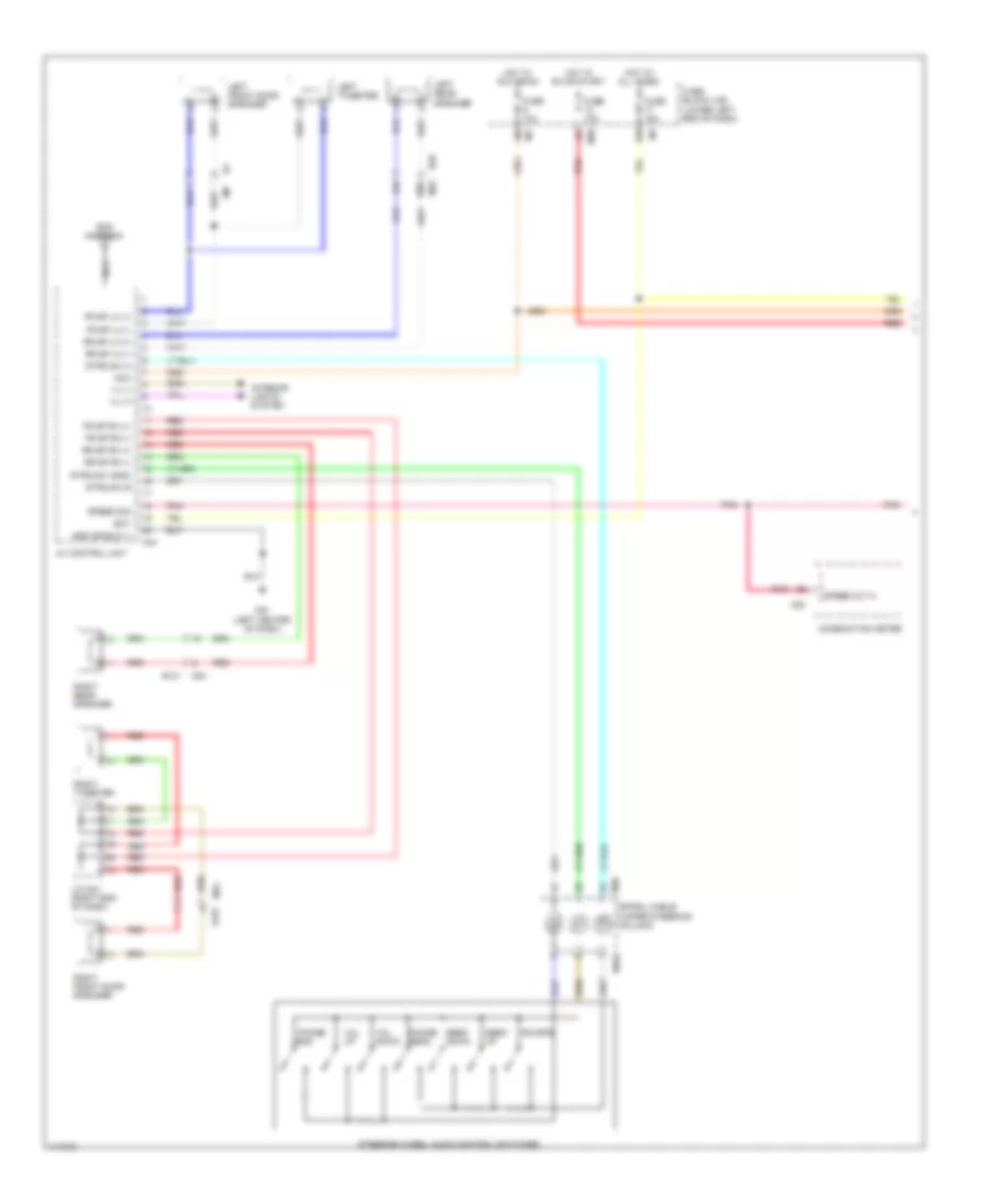
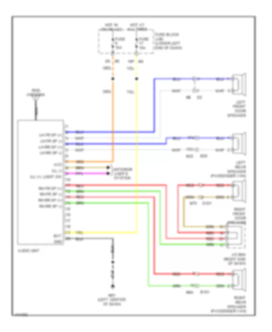
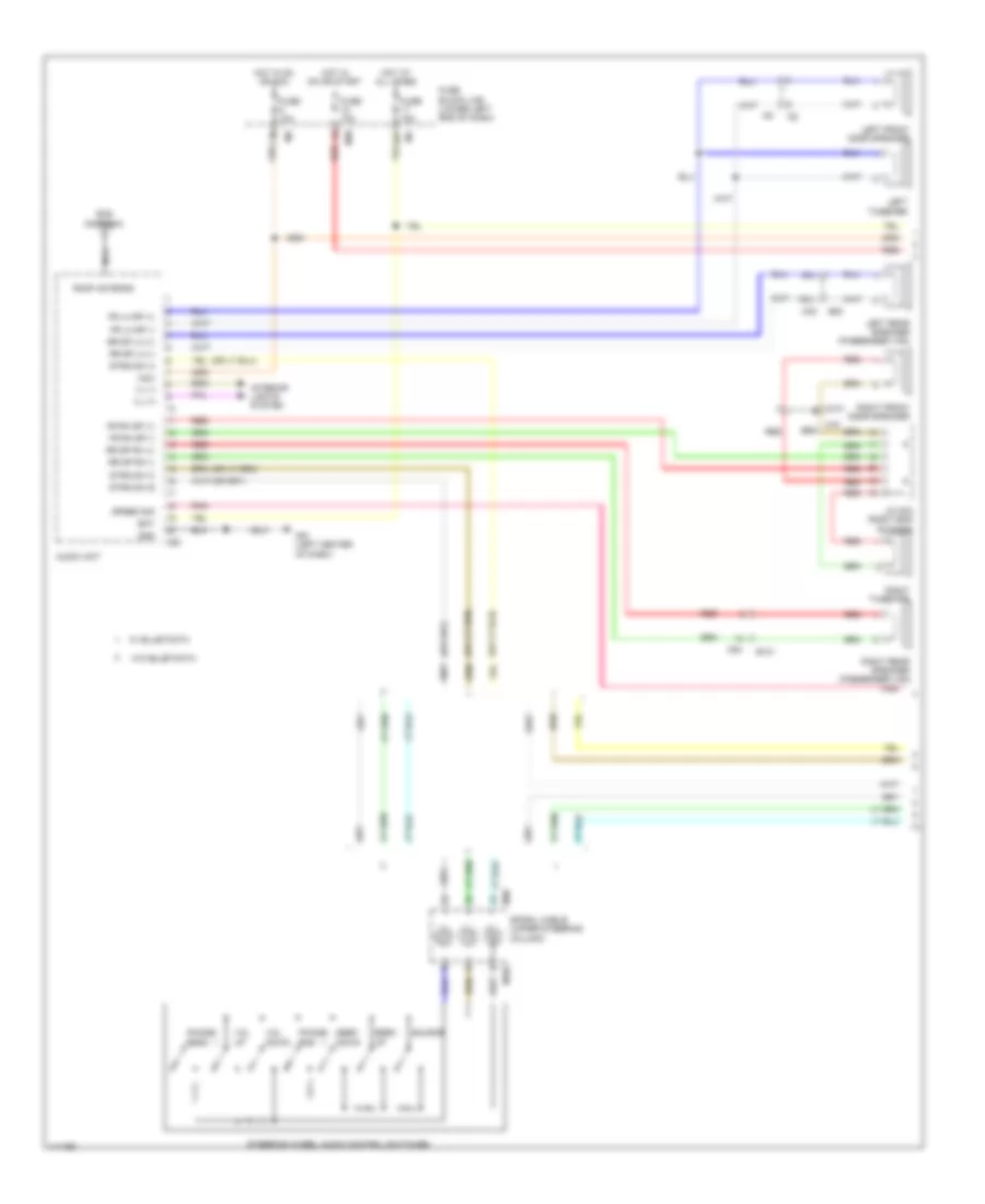
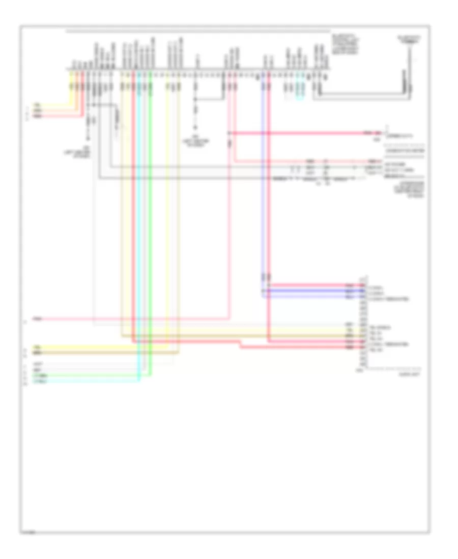
NAVIGATION
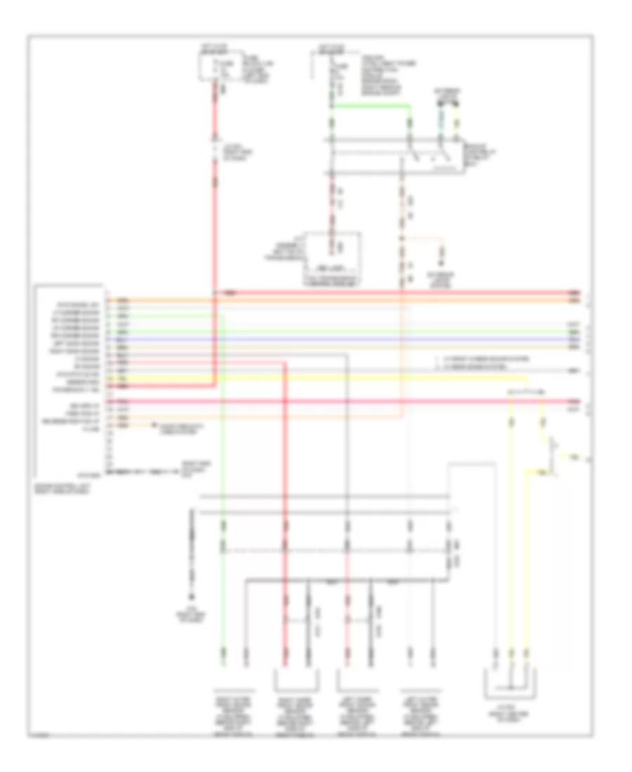
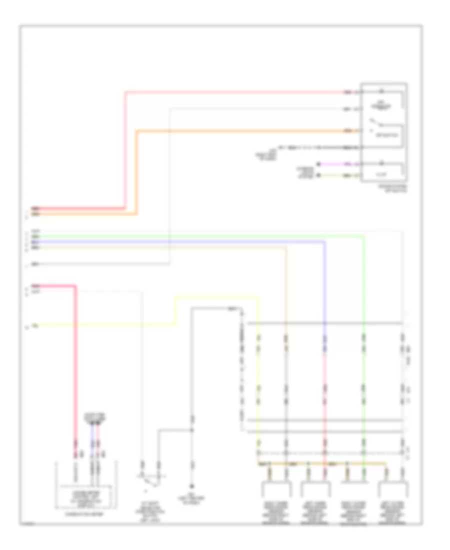
Navigation Wiring Diagram (1 of 2) for Nissan NVHD SL 2014 3500
List of elements for Navigation Wiring Diagram (1 of 2) for Nissan NVHD SL 2014 3500:
- 100j
- 16p
- 94j
- Acc
- Av control unit
- B101
- B20
- Bat
- Combination meter
- D101
- Fr sp lh (+)
- Fr sp lh (-)
- Fr sp rh (+)
- Fr sp rh (-)
- Fuse 10a
- Fuse 15a
- Fuse block (j/b) (lower left end of dash)
- Gnd (shield 1)
- Hot at all times
- Hot in acc or on
- Hot in on or start
- Ill (+)
- Ill (-)
- Interior lights system
- J/c m04 (right end of dash)
- Left front door speaker
- Left rear speaker
- Left tweeter
- M102
- M23
- M30
- M32
- M39
- M44
- M61 (left center of dash)
- M75
- M84
- Nca
- Phone/ end
- Phone/ send
- Pnk
- Red
- Right front door speaker
- Right rear speaker
- Right tweeter
- Rod antenna
- Rr sp lh (+)
- Rr sp lh (-)
- Rr sp rh (+)
- Rr sp rh (-)
- Seek down
- Seek up
- Source
- Speed out 8
- Speed sig
- Spiral cable (upper steering column)
- Steering wheel audio control switches
- Strg sw (gnd)
- Strg sw a
- Strg sw b
- Vol down
- Vol up
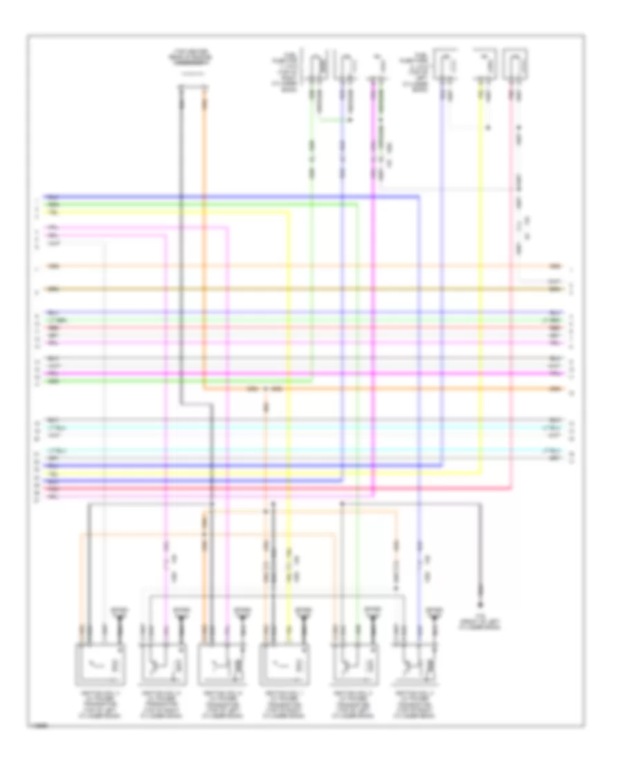
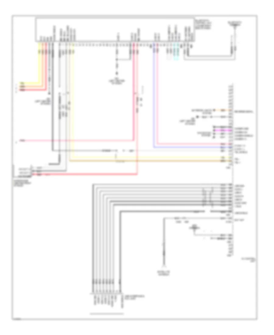
Navigation Wiring Diagram (2 of 2) for Nissan NVHD SL 2014 3500
List of elements for Navigation Wiring Diagram (2 of 2) for Nissan NVHD SL 2014 3500:
- Acc
- Audio gnd
- Audio l
- Audio out+
- Audio out-
- Audio r
- Audio shield
- Av control unit
- B (+)
- Bt antenna
- Camera (+)
- Camera gnd
- Camera on
- Camera-(shield)
- Can h1
- Can h2
- Can jumper 1
- Can jumper 2
- Can l1
- Can l2
- Cont 4
- Cont 6
- Exterior lights system
- Gnd
- Gps antenna
- Ign
- M can 1 h
- M can 1 l
- M129
- M350
- M46
- M61 (left center of dash)
- M63
- M65
- M69
- M85
- M86
- M87
- Mic in (+)
- Mic in (-) (gnd)
- Mic out (+)
- Mic out (-)
- Mic power
- Mic shield
- Microphone (center front of roof)
- Navigation system
- Nca
- Pnk
- Red
- Reverse signal
- Sat ant
- Satellite antenna
- Shield
- Shield bt antenna
- Speed
- Tel +
- Tel -
- Tel shield
- Usb d (+)
- Usb d (-)
- Usb d+
- Usb d-
- Usb gnd
- Usb interface & aux jack
- Usb shield
- V bus
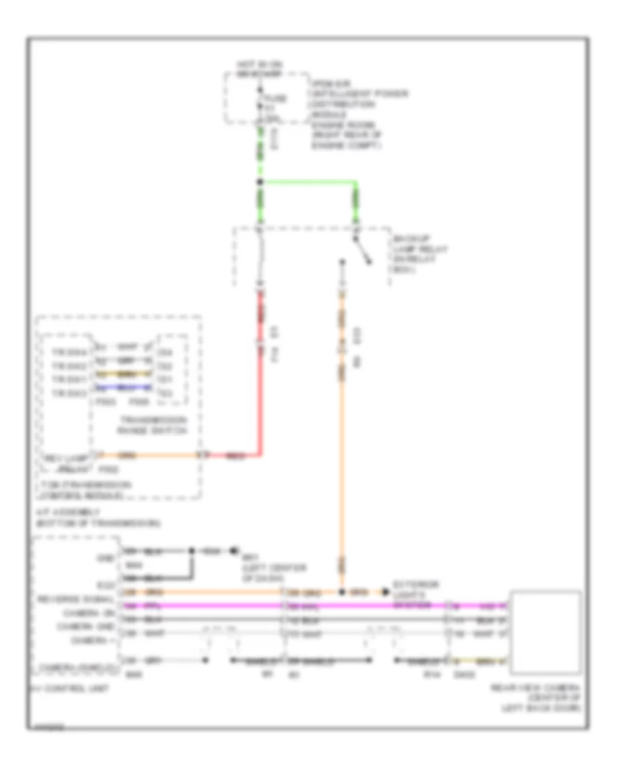
Rear View Camera Wiring Diagram for Nissan NVHD SL 2014 3500
List of elements for Rear View Camera Wiring Diagram for Nissan NVHD SL 2014 3500:
- (bottom of transmission)
- A/t assembly
- Av control unit
- Backup lamp relay (in relay box)
- Camera +
- Camera gnd
- Camera on
- Camera-(shield)
- D402
- E119
- E5 f14
- E53
- Eq3
- Exterior lights system
- F503
- F505
- Fuse 10a
- Gnd
- Hot in on or start
- Ipdm e/r (intelligent power distribution module engine room) (right rear of engine compt)
- M44
- M46
- M61 (left center of dash)
- R14
- Rear view camera (center of left back door)
- Red
- Rev lamp relay f502
- Reverse signal
- Shield
- Tcm (transmission control module)
- Tr sw1
- Tr sw2
- Tr sw3
- Tr sw4
- Transmission range switch
Sonar Wiring Diagram (1 of 2) for Nissan NVHD SL 2014 3500
List of elements for Sonar Wiring Diagram (1 of 2) for Nissan NVHD SL 2014 3500:
- (bottom of transmission)
- (right center of dash)
- (right end of dash) m79
- 31g
- 32g
- 36g
- 42g
- 43g
- A/t assembly
- Backup lamp relay (in relay box)
- Computer data lines system
- E119
- E152
- E160
- E161
- E170
- E171
- E5 f14
- E53
- Exterior lights system
- F502
- Fuse 10a
- Fuse block (j/b) (lower left end of dash)
- Hot in on or start
- Ipdm e/r (intelligent power distribution module engine room) (right rear of engine compt)
- J/c m02
- J/c m04 (right end of dash)
- K-line
- Left back sonar
- Left inner front sonar sensor (if equipped) (behind left side of front fascia)
- Left outer front sonar sensor (if equipped) (behind left end of front fascia)
- Lf corner sonar
- Lf sonar
- Lr corner sonar
- M31
- M39
- M79 (right end of dash)
- Nca
- Park pos i/p
- Pnk
- Power suply ign
- Red
- Rev lamp
- Reverse position i/p
- Rf corner sonar
- Rf sonar
- Right back sonar
- Right inner front sonar sensor (if equipped) (behind right side of front fascia)
- Right outer front sonar sensor (if equipped) (behind right end of front fascia)
- Rr corner sonar
- Sensor gnd
- Sonar control unit (right side of dash)
- Sys cancel sw
- Sys gnd
- Sys status ind
- Tcm (transmission control module)
- Veh spd i/p
- W/ front & rear sonar system
- W/ rear sonar system
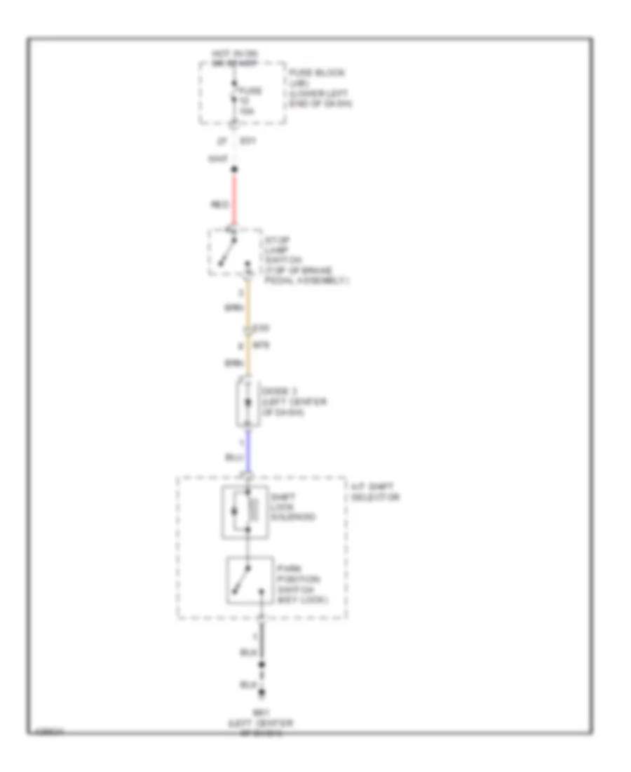
Sonar Wiring Diagram (2 of 2) for Nissan NVHD SL 2014 3500
List of elements for Sonar Wiring Diagram (2 of 2) for Nissan NVHD SL 2014 3500:
- 24c
- 25c
- 26c
- 27c
- 28c
- 29c
- 33g
- 34g
- 35g
- 44g
- 45g
- 46g
- A/t shift selector (park position switch (key lock)
- Can h
- Can l
- Combination meter
- Computer data lines system
- E152
- E41
- Illum
- Interior lights system
- Left inner rear sonar sensor (behind left side of rear bumper)
- Left outer rear sonar sensor (behind left end of rear bumper)
- M23
- M24
- M31
- M61 (left center of dash)
- M79 (right end of dash)
- Off indicator
- Off switch
- Pnk
- Red
- Right inner rear sonar sensor (behind right side of rear bumper)
- Right outer rear sonar sensor (behind right end of rear bumper)
- Shield
- Sonar system off switch
- Spd out 8
- Unified meter control unit (w/ information display)
POWER DISTRIBUTION
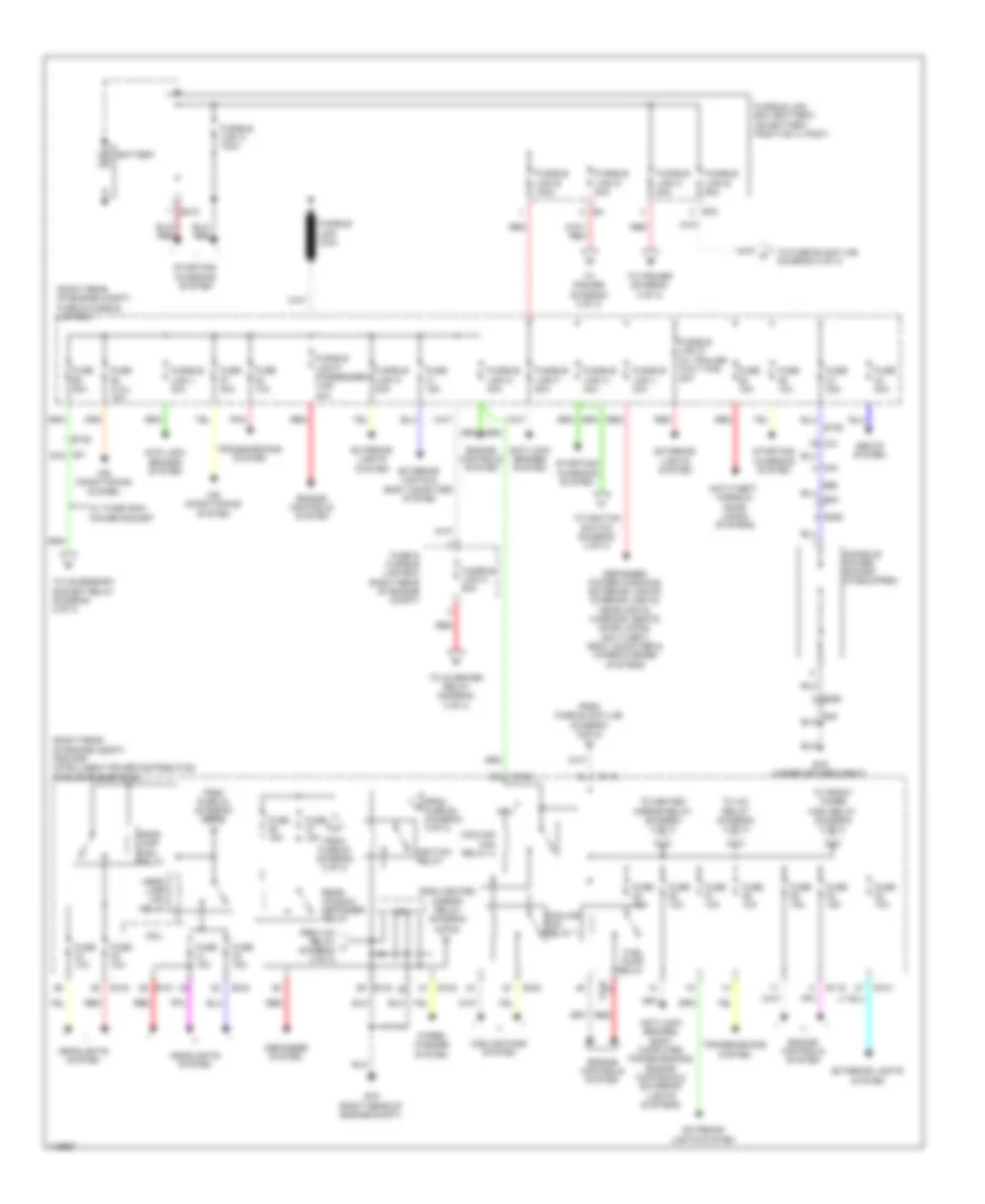
Power Distribution Wiring Diagram (1 of 3) for Nissan NVHD SL 2014 3500
List of elements for Power Distribution Wiring Diagram (1 of 3) for Nissan NVHD SL 2014 3500:
- (right rear of engine compt) fuse & fusible link box
- (right rear of engine compt) ipdm e/r (intelligent power distribution module engine room)
- 7g m31
- Air conditioning system
- Anti-lock brakes system
- Anti-lock brakes, body computer, transmissions, engine controls & exterior lights systems
- Anti-theft, horns & door locks systems
- B19 (under driver's seat)
- B350
- B40
- Battery
- Console power socket (if equipped)
- Cooling fan relay 1
- Cooling fan relay 2
- Cooling fans system
- Cpu
- Defogger system
- Defogger, power windows, exterior lights, interior lights, headlights, warning, seats, door locks, anti-theft, body computer & wiper/washer systems
- E119
- E120
- E121
- E122
- E123
- E124
- E15 (right rear of engine compt)
- E152
- E210
- E76
- Engine controls system
- Exterior lights & body computer system
- Exterior lights system
- From a/c relay l (diagram 3 of 3)
- From fuse 43 (diagram 3 of 3)
- From fuse 52 (diagram 3 of 3)
- From fuse 53 (diagram 3 of 3)
- From fuse block (j/b) (diagram 2 of 3)
- From heated mirror relay (diagram 3 of 3)
- Fuel pump relay
- Fuse & fusible link box (right rear of engine compt)
- Fuse (4.0l) 10a
- Fuse 10a
- Fuse 15a
- Fuse 20a
- Fuse 30a
- Fusible link 100a
- Fusible link a 140a
- Fusible link b 60a
- Fusible link box (battery) (on battery positive (+) post)
- Fusible link c 80a
- Fusible link d 80a
- Fusible link e 100a
- Fusible link f 50a
- Fusible link g (w/ trailer tow 7 pin) 30a
- Fusible link h 40a
- Fusible link j 40a
- Fusible link k 30a
- Fusible link l 30a
- Fusible link m 40a
- Fusible link n 60a
- Fusible link p (passenger van) 40a
- Head- lamp high relay
- Head- lamp low relay
- Headlights system
- Ignition relay
- M31 97g
- M40
- Pnk
- Rear window defogger relay
- Red
- Seats system
- Starting/ charging system
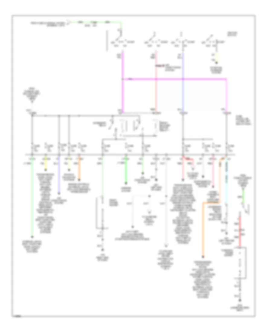
- To a/c relay (diagram 3 of 3)
- To accessory socket relay (diagram 2 of 3)
- To front wiper high relay (diagram 3 of 3)
- To fuse block (j/b) (diagram 2 of 3)
- To heated mirror relay (diagram 3 of 3)
- To ignition switch (diagram 2 of 3)
- To inverter relay (diagram 3 of 3)
- To ipdm/er (diagram 3 of 3)
- Transmissions system
- W/ third row power socket
- Wiper/ washer system
Power Distribution Wiring Diagram (2 of 3) for Nissan NVHD SL 2014 3500
List of elements for Power Distribution Wiring Diagram (2 of 3) for Nissan NVHD SL 2014 3500:
- (diagram 1 of 3)
- 10p
- 11p m4
- 15p m4
- 16p m4
- 1n m3
- 1r m38
- 1s e50
- 1t e51
- 2t e51
- 3q m39
- 4q m39
- 7n m3
- 7q m39
- 96g
- Acc
- Accessory relay
- Accessory socket relay (back side of fuse block (j/b))
- Air conditioning system
- Anti-theft, anti-lock brakes, engine controls & starting/charging systems
- B19 (under driver's seat)
- B20
- E152
- Engine controls, exterior lights, anti-lock brakes & transmissions
- From fuse & fusible link box (diagram 1 of 3)
- From fuse & fusible link box f
- From fusible link box (battery) (diagram 1 of 3)
- Front blower motor relay 1
- Front power socket
- Fuse 10a
- Fuse 15a
- Fuse 20a
- Fuse block (j/b) (lower left end of dash)
- Ig2 red
- Ignition switch
- Interior lights, body computer, door locks & anti-theft systems
- M31
- M32 91j
- M39
- M57 (left end of dash)
- M61 (left center of dash)
- M79 (right end of dash)
- Mirrors system
- Off
- Red
- Sound & navigation systems
- Start
- Starting/ charging system
- Third row power socket
- To inverter relay (diagram 3 of 3)
- To ipdm e/r (intelligent power distribution module engine room) (diagram 1 of 3)
- To j/c m04 (diagram 3 of 3)
- Wiper/ washer & body computer systems
Power Distribution Wiring Diagram (3 of 3) for Nissan NVHD SL 2014 3500
List of elements for Power Distribution Wiring Diagram (3 of 3) for Nissan NVHD SL 2014 3500:
- (base of left "d" pillar) r15
- (in relay box) inverter relay
- (right rear of engine compt) ipdm e/r (intelligent power distribution module engine room)
- 27g
- A/c relay
- A/t shift selector (parking position switch (key lock))
- Ac 120v front outlet
- Ac 120v outlet main switch
- Ac 120v rear outlet
- Ac o/p 1
- Ac o/p 2
- Ac sw sig
- Air conditioning system
- B19 (under driver's seat)
- B350
- B40
- B69
- Computer data lines system
- Cpu
- Defogger system
- Drive ind
- E118
- E119
- E120
- E121
- E122
- E123
- E124
- E152
- Ecm relay
- Engine controls system
- Exterior lights system
- From fuel pump relay (diagram 1 of 3)
- From fuse & fusible link box (diagram 1 of 3)
- From fuse block (j/b) (diagram 2 of 3)
- From fusible link box (battery) (diagram 1 of 3)
- Front fog lamp relay (if equipped)
- Front wiper high relay
- Front wiper relay
- Fuse 10a
- Fuse 15a
- Fuse 20a
- Fuse 30a
- Gnd
- Headlights system
- Heated mirror relay
- I/p prk nsig
- Interior lights & exterior lights systems
- Interior lights system
- Interior lights, exterior lights & headlights systems
- Inverter unit (base of left "d" pillar)
- J/c m04 (right end of dash)
- M31
- M40
- M61 (left center of dash)
- Pnk
- Pwr
- R10
- R11
- R13 (left "d" pillar)
- Red
- Rly o/p
- Tail lamp relay
- Throttle control motor relay
- To fuse 47 (diagram 1 of 3)
- To headlight low relay (diagram 1 of 3)
- To ignition relay (diagram 1 of 3)
- To rear window defogger relay (diagram 1 of 3)
- Transmissions, engine controls & anti-theft systems
- Wiper/ washer system
POWER DOOR LOCKS
Power Door Locks Wiring Diagram (1 of 2) for Nissan NVHD SL 2014 3500
List of elements for Power Door Locks Wiring Diagram (1 of 2) for Nissan NVHD SL 2014 3500:
- (right rear of engine compt) ipdm e/r
- +ig
- Acc sw
- B132 (under front passenger's seat)
- B69
- Bat (f/l)
- Bat (fuse)
- Batt saver output
- Body control module (bcm) (behind instrument cluster)
- Buzzer
- Can h
- Can l
- Can-h
- Can-l
- Cdl lock sw
- Cdl unlock sw
- Closed
- Combination meter
- Computer data lines system
- Cpu
- D402
- D606
- Door ind
- Door lock output
- Door sw (as)
- Door sw (dr)
- Door sw (rl)
- Door sw (rr)
- Door unlck out (dr)
- Dr unlck out (other)
- E122
- E124
- E15 (right rear of engine compt)
- Exterior lights system
- Fuse 10a
- Fuse block (j/b) (lower left end of dash)
- Gnd
- Gnd (pwr)
- Gnd (sig)
- H/lp hi
- H/lp lo
- Headlights system
- Horn rly cont
- Horns system
- Hot at all times
- Hot in on or acc
- Hot in on or start
- Ign sw
- Ignition relay
- Inserted
- Interior lights system
- J/c m04 (right end of dash)
- Key cyl lock sw
- Key cyl unlock sw
- Key sw
- Key switch
- Left front door switch (left "b" pillar)
- Left lower back door switch (lower right side of left back door)
- Lh flasher output
- M18
- M19
- M20
- M23
- M24
- M39
- M40
- M57 (left end of dash)
- M61 (left center of dash)
- M84 b101
- Open
- Pnk
- Power
- R13 (left "d" pillar)
- R14
- R24
- Red
- Remote keyless entry receiver (if equipped) (right center of dash)
- Removed
- Rh flasher output
- Right lower back door switch (lower left side of right back door)
- Right upper back door switch (above right rear door in roof)
- Room lamp output
- Secondary sliding door switch (w/ high roof) (lower rear of sliding door)
- Security ind
- Security ind output
- Signal
- Sliding door contact switch (door) (base of right "b" pillar)
- Sliding door contact switch (pillar) (base of right "b" pillar)
- Sliding door switch (base of right "c" pillar)
- Unified meter control unit (w/ information display)
Power Door Locks Wiring Diagram (2 of 2) for Nissan NVHD SL 2014 3500
List of elements for Power Door Locks Wiring Diagram (2 of 2) for Nissan NVHD SL 2014 3500:
- 91g
- Actuator
- B101
- B132 (under front passenger's seat)
- Back door lock assembly
- Closed
- Cpu
- D101
- D101 m75
- D102
- Door lock
- Door unlock
- E152
- E24 (left rear of engine compt)
- E71
- Fuse & fusible link box (right rear of engine compt)
- Fuse 15a
- Fusible link j 40a
- Gnd
- Horn (high) (left front of engine e13 compt)
- Horn (low) (left front of engine e72 compt)
- Horn relay (in relay box)
- Hot at all times
- Key cylinder switch
- Left front door lock assembly
- Lock
- M2 r2
- M31
- M57 (left end of dash)
- M61 (left center of dash)
- M74
- M75
- M79 (right end of dash)
- M8 d2
- M84
- M84 b101
- M9 d1
- Main power window & door lock/ unlock switch
- Motor
- Open
- Pre-wiring for telematics control module (center of dash)
- R1 m1
- R13 (left "d" pillar)
- R24 d606
- Red
- Right front door lock actuator
- Right front door switch (right "b" pillar)
- Right power window & door lock/ unlock switch
- Sliding door contact switch (door) (base of right "b" pillar)
- Sliding door contact switch (pillar) (base of right "b" pillar)
- Sliding door lock assembly
- Unlock
POWER MIRRORS
Auto Anti-dazzling Inside Mirror Wiring Diagram for Nissan NVHD SL 2014 3500
List of elements for Auto Anti-dazzling Inside Mirror Wiring Diagram for Nissan NVHD SL 2014 3500:
- Auto anti-dazzling inside mirror
- Fuse 10a
- Fuse block (j/b) (lower left end of dash)
- Gnd
- Hot in on or start
- Ign
- M39
- R13 (left "d" pillar)
- Red
Power Mirrors Wiring Diagram for Nissan NVHD SL 2014 3500
List of elements for Power Mirrors Wiring Diagram for Nissan NVHD SL 2014 3500:
- 11p m4
- Changeover switch
- D102
- Defogger
- Defogger system
- Door mirror remote control switch
- Down
- Fuse 10a
- Fuse block (j/b) (lower left end of dash)
- Hot in on or acc
- Interior lights system
- Left
- Left door mirror
- M57 (left end of dash)
- M74
- Mirror switch
- Off
- Pnk
- Red
- Right
- Right door mirror
- W/ heated mirrors
- W/o heated mirrors
POWER SEATS
Driver Power Seat Wiring Diagram for Nissan NVHD SL 2014 3500
List of elements for Driver Power Seat Wiring Diagram for Nissan NVHD SL 2014 3500:
- (left end of dash) m57
- 91g m31
- B217
- B231
- B45
- B45 b211
- B69
- B7 (under driver's seat)
- Bat
- Body control module (bcm) (behind instrument cluster)
- Bwd
- Can-h
- Can-l
- Computer data lines system
- Down
- E152
- Front lifting motor
- Front lifting switch
- Fuse & fusible link box (right rear of engine compt)
- Fusible link j 40a
- Fwd
- Gnd
- Hot at all times
- Left power seat switch
- Left reclining motor
- Left sliding motor
- M20
- M40
- P/w
- Pnk
- Rear lifting motor
- Rear lifting switch
- Reclining switch
- Red
- Sliding switch
Heated Seats Wiring Diagram for Nissan NVHD SL 2014 3500
List of elements for Heated Seats Wiring Diagram for Nissan NVHD SL 2014 3500:
- 94g
- B101
- B105
- B117 (under front passenger's seat)
- B213
- B302
- B69
- B7 (under driver's seat)
- E152
- Fuse & fusible link box (right rear of engine compt)
- Fuse 10a
- Fuse 20a
- Fuse block j/b (lower left end of dash)
- Heated seat relay
- Hot at all times
- Hot in on or start
- Interior lights
- Left front heated seat switch
- Left front seat heater
- M31 98g
- M39
- M40
- M61 (left center of dash)
- M84
- Red
- Right front heated seat switch
- Right front seat heater
- System
POWER WINDOWS
Power Windows Wiring Diagram for Nissan NVHD SL 2014 3500
List of elements for Power Windows Wiring Diagram for Nissan NVHD SL 2014 3500:
- (right end of dash) j/c m04
- 91g
- Acc sw
- As down
- As up
- B69
- Bat
- Batt (f/l)
- Body control module (bcm) (behind instrument cluster)
- Central lock sw
- Central unlock sw
- Cpu
- D101
- D102
- Door sw (as)
- Door sw (dr)
- Dr down
- Dr up
- E152
- Encoder
- Encoder gnd
- Encoder power
- Encoder sig1
- Fuse & fusible link box (right rear of engine compt)
- Fuse 10a
- Fuse block (j/b) (lower left end of dash)
- Fusible link j 40a
- Gnd
- Hot at all times
- Hot in on or acc
- Hot in on or start
- Ign
- Ign sw
- Illumination
- Left front door switch (left "b" pillar)
- Left front power window motor
- Lock
- Lock switch
- M18
- M19
- M20
- M31
- M39
- M40
- M57 (left end of dash)
- M74
- M75
- M79 (right end of dash)
- M84 b101
- Main power window & door lock/unlock switch
- Power window lock switch
- Pwr sply (rap)
- Pwr window
- Pwr window pwr sply (batt)
- Red
- Right front
- Right front door switch (right "b" pillar)
- Right front power window motor
- Right power window & door lock/unlock switch
- Un lock
- Unlock
RADIO
Base Radio Wiring Diagram for Nissan NVHD SL 2014 3500
List of elements for Base Radio Wiring Diagram for Nissan NVHD SL 2014 3500:
- 100j
- 94j
- Acc
- Audio unit
- B101
- B20
- Bat
- D101
- Fuse 10a
- Fuse 15a
- Fuse block (j/b) (lower left end of dash)
- Gnd
- Hot at all times
- Hot in on or acc
- Ill (+), light sw
- Ill (-)
- Interior lights system
- J/c m04 (right end of dash)
- Left front door speaker
- Left rear speaker (passenger van)
- Lh fr sp (+)
- Lh fr sp (-)
- Lh rr sp (+)
- Lh rr sp (-)
- M32
- M4 16p
- M61 (left center of dash)
- M75
- M84
- Nca
- Red
- Rh fr sp (+)
- Rh fr sp (-)
- Rh rr sp (+)
- Rh rr sp (-)
- Right front door speaker
- Right rear speaker (passenger van)
- Rod antenna
Mid-Line Radio Wiring Diagram (1 of 2) for Nissan NVHD SL 2014 3500
List of elements for Mid-Line Radio Wiring Diagram (1 of 2) for Nissan NVHD SL 2014 3500:
- 16p
- 94j
- Acc
- Audio unit
- B101
- B20
- Bat
- D101
- Fr lh sp (+)
- Fr lh sp (-)
- Fr rh sp (+)
- Fr rh sp (-)
- Fuse 10a
- Fuse 15a
- Fuse block (j/b) (lower left end of dash)
- Gnd
- Hot at all times
- Hot in on or acc
- Hot in on or start
- Ill (+)
- Ill (-)
- Interior lights system
- J/c m04 (right end of dash)
- Left front door speaker
- Left rear speaker (passenger van)
- Left tweeter
- M102
- M30
- M32
- M39
- M50
- M61 (left center of dash)
- M75
- M84
- Nca
- Phone/ end
- Phone/ send
- Pnk
- Red
- Right front door speaker
- Right rear speaker (passenger van)
- Right tweeter
- Rod antenna
- Roof antenna
- Rr sp lh (+)
- Rr sp lh (-)
- Rr sp rh (+)
- Rr sp rh (-)
- Seek down
- Seek up
- Source
- Speed sig
- Spiral cable (upper steering column)
- Steering wheel audio control switches
- Strg sw a
- Strg sw b
- Strg sw c
- Vol down
- Vol up
Mid-Line Radio Wiring Diagram (2 of 2) for Nissan NVHD SL 2014 3500
List of elements for Mid-Line Radio Wiring Diagram (2 of 2) for Nissan NVHD SL 2014 3500:
- Acc
- Audio out (+)
- Audio out (-)
- Audio shield
- Audio unit
- B (+)
- Bt antenna
- Can h1
- Can h2
- Can jmpr1
- Can jmpr2
- Can l1
- Can l2
- Combination meter
- Cont 3
- Cont 6
- Gnd
- Ign
- Ladder in 1
- Ladder in 2
- Ladder in 3 gnd
- Ladder out 1
- Ladder out 2
- M can-h
- M can-h terminated
- M can-l
- M can-l terminated
- M23
- M43
- M61 (left center of dash)
- M85
- M86
- M87
- Mic in (+)
- Mic in (-) (gnd)
- Mic out (+)
- Mic out (-) (gnd)
- Mic power
- Mic shield
- Mute control
- Pnk
- Red
- Shield
- Shield bt antenna
- Speed out 8
- Speed sig
- Tel in+
- Tel in-
- Tel on
- Tel shield
Premium Sound Radio Wiring Diagram (1 of 2) for Nissan NVHD SL 2014 3500
List of elements for Premium Sound Radio Wiring Diagram (1 of 2) for Nissan NVHD SL 2014 3500:
- 100j
- 16p
- 94j
- Acc
- Av control unit
- B101
- B20
- Bat
- Combination meter
- D101
- Fr sp lh (+)
- Fr sp lh (-)
- Fr sp rh (+)
- Fr sp rh (-)
- Fuse 10a
- Fuse 15a
- Fuse block (j/b) (lower left end of dash)
- Gnd (shield 1)
- Hot at all times
- Hot in acc or on
- Hot in on or start
- Ill (+)
- Ill (-)
- Interior lights system
- J/c m04 (right end of dash)
- Left front door speaker
- Left rear speaker
- Left tweeter
- M102
- M23
- M30
- M32
- M39
- M44
- M61 (left center of dash)
- M75
- M84
- Nca
- Phone/ end
- Phone/ send
- Pnk
- Red
- Right front door speaker
- Right rear speaker
- Right tweeter
- Rod antenna
- Rr sp lh (+)
- Rr sp lh (-)
- Rr sp rh (+)
- Rr sp rh (-)
- Seek down
- Seek up
- Source
- Speed out 8
- Speed sig
- Spiral cable (upper steering column)
- Steering wheel audio control switches
- Strg sw (gnd)
- Strg sw a
- Strg sw b
- Vol down
- Vol up
Premium Sound Radio Wiring Diagram (2 of 2) for Nissan NVHD SL 2014 3500
List of elements for Premium Sound Radio Wiring Diagram (2 of 2) for Nissan NVHD SL 2014 3500:
- Acc
- Audio gnd
- Audio l
- Audio out+
- Audio out-
- Audio r
- Audio shield
- Av control unit
- B (+)
- Bt antenna
- Camera (+)
- Camera gnd
- Camera on
- Camera-(shield)
- Can h1
- Can h2
- Can jumper 1
- Can jumper 2
- Can l1
- Can l2
- Cont 4
- Cont 6
- Exterior lights system
- Gnd
- Gps antenna
- Ign
- M can 1 h
- M can 1 l
- M129
- M350
- M46
- M61 (left center of dash)
- M63
- M65
- M69
- M85
- M86
- M87
- Mic in (+)
- Mic in (-) (gnd)
- Mic out (+)
- Mic out (-)
- Mic power
- Mic shield
- Microphone (center front of roof)
- Navigation system
- Nca
- Pnk
- Red
- Reverse signal
- Sat ant
- Satellite antenna
- Shield
- Shield bt antenna
- Speed
- Tel +
- Tel -
- Tel shield
- Usb d (+)
- Usb d (-)
- Usb d+
- Usb d-
- Usb gnd
- Usb interface & aux jack
- Usb shield
- V bus
SHIFT INTERLOCK
Shift Interlock Wiring Diagram for Nissan NVHD SL 2014 3500
List of elements for Shift Interlock Wiring Diagram for Nissan NVHD SL 2014 3500:
- A/t shift selector
- Diode 3 (left center of dash)
- E51
- E55
- Fuse 10a
- Fuse block (j/b) (lower left end of dash)
- Hot in on or start
- M61 (left center of dash)
- M78
- Park position switch (key lock)
- Red
- Shift lock solenoid
- Stop lamp switch (top of brake pedal assembly)
STARTING/CHARGING
Charging Wiring Diagram for Nissan NVHD SL 2014 3500
List of elements for Charging Wiring Diagram for Nissan NVHD SL 2014 3500:
- 4.0l
- 5.6l
- Battery
- Charge indicator
- Combination meter
- E201
- E203 (right rear of engine compt)
- E204
- E206
- E207
- E40
- E70
- Fuse & fusible link box (right rear of engine compt)
- Fuse 10a
- Fuse block (j/b) (lower left end of dash)
- Fusible link a 140a
- Fusible link box (battery) (on battery positive (+) post)
- Generator
- Hot at all times
- Hot in on or start
- J/c m04 (right end of dash)
- M31 38g
- M39
- Red
- Unified meter control unit (w/ information display)
Starting Wiring Diagram for Nissan NVHD SL 2014 3500
List of elements for Starting Wiring Diagram for Nissan NVHD SL 2014 3500:
- 10g
- 96g
- A/t assembly (bottom of transmission)
- Acc
- Battery
- Can-h
- Can-l
- Computer data lines system
- Cpu
- E118
- E119
- E120
- E122
- E124
- E15 (right rear of engine compt)
- E152
- E207
- E51
- E70
- E76
- Engine controls system
- F14
- F502
- F503
- F505
- Fuse & fusible link box (right rear of engine compt)
- Fuse 10a
- Fuse block (j/b) (lower left end of dash)
- Fusible link box (battery) (on battery positive (+) post)
- Fusible link c 80a
- Fusible link h 40a
- Hot at all times
- Hot in on or start
- Ig+
- Ignition relay
- Ignition switch
- Intelligent power distribution module engine room (ipdm e/r) (right rear of engine compt)
- M31
- M31 e152
- Off
- Pnk
- Red
- Start
- Start relay
- Starter motor
- Starter relay
- Tcm (transmission control module)
- Tr sw 1
- Tr sw 2
- Tr sw 3
- Tr sw 4
- Transmission range switch
SUPPLEMENTAL RESTRAINTS
Supplemental Restraints Wiring Diagram (1 of 2) for Nissan NVHD SL 2014 3500
List of elements for Supplemental Restraints Wiring Diagram (1 of 2) for Nissan NVHD SL 2014 3500:
- (base of left "b" pillar) left front seat belt pre-tensioner
- (base of right "b" pillar) b104
- (in right front seat belt buckle assembly) right seat belt buckle switch
- (or shield)
- (right side of dash) front passenger air bag module
- Air bag diagnosis sensor unit (under front of center console)
- Air bag w/l
- As1 (+)
- As1 (-)
- As2 (+)
- As2 (-)
- B104 (base of right "b" pillar)
- B113
- B117 (under front passenger's seat)
- C-lh1 (+)
- C-lh1 (-)
- C-lh2 (+)
- C-lh2 (-)
- C-rh1 (+)
- C-rh1 (-)
- C-rh2 (+)
- C-rh2 (-)
- Can-h
- Can-l
- Computer data lines system
- Deployment info output
- Dr1 (+)
- Dr1 (-) & dr2 (-)
- Dr2 (+)
- Eczs1 (+)
- Eczs1 (-)
- Fuse 10a
- Fuse block (j/b) (lower left end of dash)
- Gnd
- Hot at all times
- Hot in on or start
- Ign
- Joint connector b02 (under front of center console)
- K-line
- Lh satellite sens (+)
- Lh satellite sens (-)
- Lh seat belt buckle sw
- Lr satellite sens (+)
- Lr satellite sens (-)
- M35
- M39
- M61 (left center of dash)
- P-lh1 (+)
- P-lh1 (-)
- P-rh1 (+)
- P-rh1 (-)
- Pnk
- Red
- Rh satellite sens (+)
- Rh satellite sens (-)
- Rh seat belt buckle sw
- Right front seat belt pre-tensioner (base of right "b" pillar)
- Right front side air bag (satellite) sensor (if equipped) (base of right "b" pillar)
- Right front side air bag module (if equipped) (outer side of right seat back)
- Right rear side air bag (satellite) sensor (passenger van) (base of right "c" pillar)
- Right side front curtain air bag module (w/ side air bags)
- Right side rear curtain air bag module (passenger van) (over right rear side window, in roof rail)
- Rr satellite sens (+)
- Rr satellite sens (-)
- S-lh (+)
- S-lh (-)
- S-rh (+)
- S-rh (-)
- Shield
- W/ passenger van
- W/ side air bag
Supplemental Restraints Wiring Diagram (2 of 2) for Nissan NVHD SL 2014 3500
List of elements for Supplemental Restraints Wiring Diagram (2 of 2) for Nissan NVHD SL 2014 3500:
- (or shield)
- (upper steering column) spiral cable
- (w/ information display) unified meter control unit
- 71g
- 72g
- 82g
- A/b warning
- Air bag ind
- B5 (left "b" pillar)
- B7 (under driver's seat)
- Can-h
- Can-l
- Collision notify
- Combination meter
- Computer data lines system
- Crash zone sensor (center front of engine compt)
- Dgr(+)
- Dgr(-)
- Driver air bag module
- Driver seat belt ind
- E14 (right side of engine compt)
- E152
- Gnd
- Joint connector b01 (under front of center console)
- Joint connector m04 (right end of dash)
- Left front side air bag (satellite) sensor (if equipped) (base of left "b" pillar)
- Left front side air bag module (if equipped) (outer side of left seat back)
- Left rear side air bag (satellite) sensor (w/ passenger van) (base of left "c" pillar)
- Left seat belt buckle switch (in left front seat belt buckle assembly)
- Left side front curtain air bag module (w/ side air bags)
- Left side rear curtain air bag module (passenger van) (over left rear side window, in roof rail)
- M101
- M103
- M23
- M24
- M31
- M40 b69
- M61 (left center of dash)
- M84 b101
- Passenger seat belt ind
- Pnk
- Pre-wiring (telematics control module) (center of dash)
- Red
- Shield
- W/ passenger van
- W/ side air bag
TRANSMISSION
Transmission Wiring Diagram (1 of 2) for Nissan NVHD SL 2014 3500
List of elements for Transmission Wiring Diagram (1 of 2) for Nissan NVHD SL 2014 3500:
- A/t assembly (bottom of transmission)
- A/t fluid temperature sensor
- Atf sens
- C1 (vin)
- C2 (vout)
- C3 (gnd)
- Can-h
- Can-l
- Common
- Computer data lines lines system
- Computer data lines system
- Control module (tcm)
- Direct clutch solenoid valve
- E9 (right rear of engine compt)
- Exterior lights system
- F14 e5
- F502
- F503
- F504
- F505
- F506
- Front brake solenoid valve
- Gnd-1
- Gnd-2
- High & low reverse clutch solenoid valve
- Input clutch solenoid valve
- Input speed sensor 1
- Input speed sensor 2
- K-line
- Line pressure solenoid valve
- Linear sol
- Low coast brake solenoid valve
- Oil press switch 2
- Output speed sen
- Output speed sen gnd
- Output speed sen power
- Output speed sensor
- Pnk
- Pressure switch 2 (lc/b)
- Red
- Rev lamp rly
- Sens 1
- Sens 2
- Start-rly
- Starting/ charging system
- Supp-1
- Supp-2
- Torque converter clutch solenoid valve
- Tr-sw1
- Tr-sw2
- Tr-sw3
- Tr-sw4
- Transmission
- Transmission range switch
- Vign
Transmission Wiring Diagram (2 of 2) for Nissan NVHD SL 2014 3500
List of elements for Transmission Wiring Diagram (2 of 2) for Nissan NVHD SL 2014 3500:
- (lower left side of dash) tcm (transmission control module) relay
- (w/ trailer tow 7 pin) tow indicator
- 4.0l
- 4q m39
- 5.6l
- A/t check indicator
- A/t oil temp indicator
- A/t shift selector
- Can-h
- Can-l
- Combination meter
- Computer data lines system
- Diode 1 (left side of dash)
- Diode 2 (left side of dash)
- Dn(-)
- E119
- E152
- E16
- E17
- Ecm (right rear of engine compt)
- F14
- Fuse & fusible link box (right rear of engine compt)
- Fuse 10a
- Fuse block (j/b) (lower left end of dash)
- Hot at all times
- Hot in acc or start
- Hot in on or start
- Hot w/ ignition relay energized
- Ipdm e/r (intelligent power distribution module engine room) (right rear of engine compt)
- J/c m04 (right end of dash)
- M23
- M24
- M3 2n
- M31 19g
- M31 2g
- M57 (left end of dash)
- M61 (left center of dash)
- M79 (right end of dash)
- Manual mode switch
- Manual shift switch
- Pnk
- Red
- Tow mode switch
- Tow mode switch (w/ trailer tow 7 pin)
- Unified meter control unit (w/ information display)
- Up(+)
WARNING SYSTEMS
Chime Wiring Diagram for Nissan NVHD SL 2014 3500
List of elements for Chime Wiring Diagram for Nissan NVHD SL 2014 3500:
- (w/ information display) unified meter control unit
- 91g m31
- Acc sw
- B69 m40
- B7 (under driver's seat)
- Bat (f/l)
- Bcm (body control module) (behind instrument cluster)
- Brake ind
- Buzzer
- Can-h
- Can-l
- Combination meter
- Combination switch (lighting & turn signal switch)
- Computer data lines system
- Dr door sw
- Driver seat belt ind
- E152
- Fuse & fusible link box (right rear of engine compt)
- Fuse 10a
- Fuse block (j/b) (lower left end of dash)
- Fusible link j 40a
- Gnd
- Hot at acc or on
- Hot at all times
- Hot in on or start
- Ign sw
- Input 1
- Input 2
- Input 3
- Input 4
- Input 5
- Instrument cluster system
- J/c m04 (right end of dash)
- Key sw
- Key switch
- Left front door switch (left front "b" pillar)
- Left seat belt buckle switch (in left front seat belt buckle assembly)
- Lighting switch
- M18
- M19
- M20
- M23
- M24
- M39
- M40 b69
- M57 (left end of dash)
- M61 (left center of dash)
- Output 1
- Output 2
- Output 3
- Output 4
- Output 5
- Parking brake switch (top of parking brake lever assembly)
- Pnk
- Red
Tire Pressure Monitoring Wiring Diagram for Nissan NVHD SL 2014 3500
List of elements for Tire Pressure Monitoring Wiring Diagram for Nissan NVHD SL 2014 3500:
- (or pnk)
- 32c
- 33c
- 34c
- 35c
- 38c
- 39c
- 40c
- 41c
- 51g
- 52g
- 53g
- 54g
- 55g
- 56g
- 57g
- 58g
- 62g
- 63g
- 64g
- 65g
- 66g
- 67g
- 68g
- 69g
- Bcm (body control module) (behind instrument cluster)
- Buzzer
- C108
- C16
- Can +(h)
- Can -(l)
- Can-h
- Can-l
- Combination meter
- Computer data lines system
- Data fl
- Data fr
- Data rl
- Data rr
- E152
- E41
- Fuse 12 10a
- Fuse 19 10a
- Fuse block (j/b) (lower left end of dash)
- Gnd
- Gnd fl
- Gnd fr
- Gnd rl
- Gnd rr
- Hazard
- Hazard sw
- Hot at all times
- Hot in on or start
- Ign
- J/c m04 (right end of dash)
- Left front tire pressure receiver (rear of left front wheelwell)
- Left rear tire pressure receiver (rear of left rear wheelwell)
- Low tire pressure warning control unit (left end of dash)
- M18
- M23
- M24
- M31
- M57 (left end of dash)
- Pnk
- Red
- Right front tire pressure receiver (rear of right front wheelwell)
- Right rear tire pressure receiver (rear of right rear wheelwell)
- Rssi
- Rssi fl
- Rssi fr
- Rssi rl
- Rssi rr
- Sig
- Tire pressure ind
- Unified meter control unit (w/ information display)
- Vcc
- Vcc fl
- Vcc fr
- Vcc rl
- Vcc rr
WIPER/WASHER
Wiper/Washer Wiring Diagram for Nissan NVHD SL 2014 3500
List of elements for Wiper/Washer Wiring Diagram for Nissan NVHD SL 2014 3500:
- (left rear of engine compt)
- Bat (f/l)
- Bcm (body control module) (behind instrument cluster)
- Can-h
- Can-l
- Combination meter
- Combination switch (wiper & washer) switch)
- Computer data lines system
- Cpu
- E121
- E122
- E124
- E15 (right rear of engine compt)
- E152
- E24
- E24 (left rear of engine compt)
- Front washer motor (in washer fluid reservoir)
- Front wiper high relay
- Front wiper motor (left rear of engine compt)
- Front wiper relay
- Fuse & fusible link box (right rear of engine compt)
- Fuse 10a
- Fuse 30a
- Fuse block (j/b) (lower left end of dash)
- Fusible link j 40a
- Gnd
- High
- Hot at all times
- Hot in on or start
- Ign sw
- Ignition relay
- Input 1
- Input 2
- Input 3
- Input 4
- Input 5
- Ipdm e/r (intelligent power distribution module engine room) (right rear of engine compt)
- J/c m04 (right end of dash)
- Low
- M18
- M20
- M23
- M24
- M28
- M31 39g
- M31 91g
- M31 9g
- M39
- M4 15p
- M57 (left end of dash)
- Move
- Output 1
- Output 2
- Output 3
- Output 4
- Output 5
- Pnk
- Red
- Stop
- Unified meter control unit (w/ information display)
- Washer fluid level switch (if equipped) (in washer fluid reservoir)
- Washer ind

 Čeština
 Dansk
Dansk Deutsch
 Ελληνικά
 English
 Español
 Suomi
Suomi Français
 Français
 עברית
עברית Hrvatski
 Magyar
 Italiano
 日本語
日本語 한국어
한국어 Nederlands
 Polski
 Português
 Português
 Română
 Русский
 Slovenčina
 Slovenščina
 Svenska
 Türkçe
 中文 (中国)