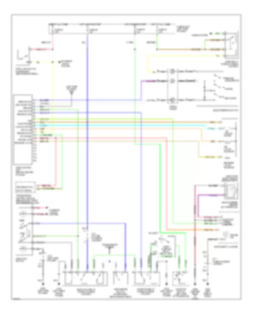
AIR CONDITIONING
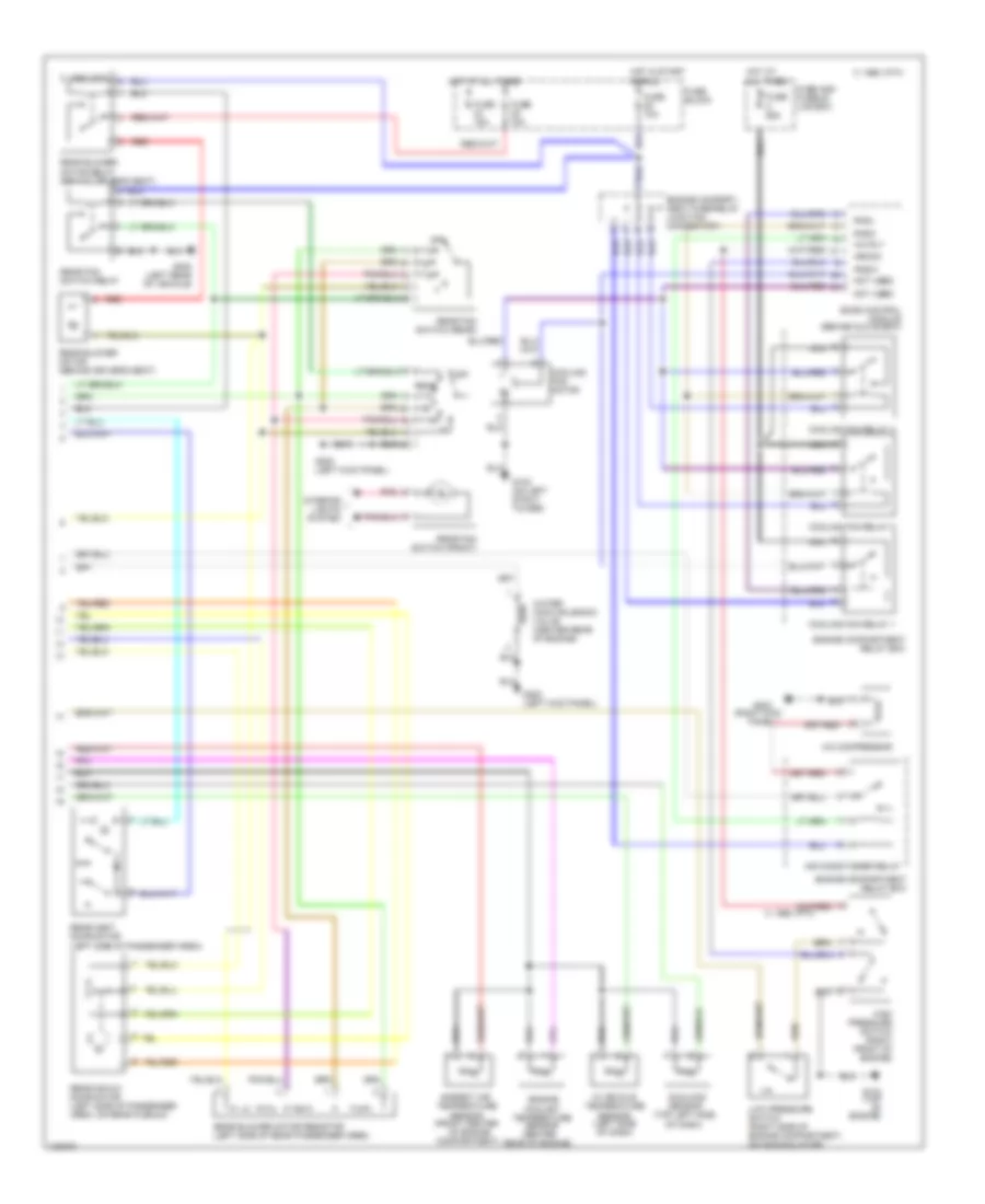
A/C Wiring Diagram, Auto A/C (1 of 2) for Nissan Quest XE 1998
 https://portal-diagnostov.com/license.html
Automotive Electricians Portal FZCO
Automotive Electricians Portal FZCO
https://portal-diagnostov.com/license.html
https://portal-diagnostov.com/license.html
Automotive Electricians Portal FZCO
Automotive Electricians Portal FZCO
List of elements for A/C Wiring Diagram, Auto A/C (1 of 2) for Nissan Quest XE 1998:
- (right kick panel) g203
- Acc
- All times
- Ambient air temp
- C 1995 vftc
- C 1995 vftc 1995 vftc c
- E/m switch
- Eatc module
- Eatc unit (center of dash)
- F/r door
- F/r door actuator
- Floor/panel
- Front air mix door motor (behind right side of dash, on plenum)
- Front blower motor
- Front blower motor relay
- Front blower speed control unit (right side of dash)
- Front intake door motor (behind right side of dash, on plenum)
- Frt blend door
- Frt blend door (cool)
- Frt blend door (warm)
- Frt blo motor relay
- Frt blower motor
- Fuse block
- Fuse 10a
- Fuse 20a
- Fuse 28 20a
- Fuse 7.5a
- Fuse and fusible link box
- Fuse block
- Fuse d 65a
- G200 (left kick panel)
- Ground
- Heater coolant temp
- Hot at
- Hot at all times
- Hot in run
- Ignition
- Ignition switch
- Illumination
- In car temp sensor
- Instrument cluster
- Interior lights system
- Lo pressure
- Lock
- Mode actuator
- Mode door motor (behind center of dash)
- Nca
- Off
- Pnk
- Position switches
- Power
- Rea water vlv sol
- Rear a/c control unit
- Rear blend dr act
- Rear vent door act
- Rr blend door
- Rr blower motor
- Rr blower motor relay
- Rr blw motor sw
- Rr cc panel
- Rr cc power
- Rr cc switch (frt)
- Rr climate ctrl panel
- Run
- Sensor power
- Start
- Sunload sensor
A/C Wiring Diagram, Auto A/C (2 of 2) for Nissan Quest XE 1998
List of elements for A/C Wiring Diagram, Auto A/C (2 of 2) for Nissan Quest XE 1998:
- (center
- (front center
- (right kick
- (top left side of dash)
- 1995 vftc c
- A/c compressor
- A/c rly
- Air conditioner relay
- Ambient air temperature
- Arcon
- C 1995 vftc
- Compartment)
- Cooling fan motor
- Cooling fan relay 1
- Cooling fan relay 2
- Cooling fan relay 3
- Eccs control module (behind glove box)
- Engine compart- ment fuse/relay junction connector 1
- Engine compartment relay box
- Engine coolant temperature sensor
- Fuse 10a
- Fuse 15a
- Fuse and fusible link box
- Fuse block
- Fuse c 65a
- G102 (on left strut tower)
- G134 (top of engine)
- G200 (left kick panel)
- G203
- G400 (left rear of vehicle)
- High pressure switch (right front of engine)
- Hot at all times
- Hot in start or run
- In vehicle temperature sensor (left side of dash)
- Interior lights system
- Low pressure switch (right side of engine compartment, on accumulator)
- Nca
- Not used
- Of engine
- Off
- Panel)
- Pdsw
- Pnk
- Radh
- Radl
- Rear
- Rear air mix door motor (left side of passenger area, on rear plenum)
- Rear blower motor (behind driver's seat)
- Rear blower motor relay (behind driver's seat)
- Rear blower motor resistor (left side of rear passenger area)
- Rear fan switch (front)
- Rear fan switch (rear)
- Rear fan switch relay
- Rear of engine)
- Rear vent door motor (left side of passenger area)
- Red
- Sensor
- Sunload sensor
- Water cock solenoid valve (center rear of engine)
A/C Wiring Diagram, Manual A/C for Nissan Quest XE 1998
List of elements for A/C Wiring Diagram, Manual A/C for Nissan Quest XE 1998:
- (on left
- (right
- A/c compressor clutch coil
- A/c press switches
- A/c rly
- Acc
- Air conditioner relay
- All times
- Arcon
- Bi-lev/flr input
- C 1995 vftc
- Cooling fan motor
- Cooling fan relay 1
- Cooling fan relay 2
- Cooling fan relay 3
- Def input
- Eccs control module (behind glove box)
- Engine compart- ment fuse/relay junction connector 1
- Engine compartment relay box
- Flr,flr/def input
- Flr/def or def input
- Fresh/recirc dr act
- Front a/c control unit
- Front air mix door motor (behind right side of dash, on plenum)
- Front blower motor
- Front blower motor relay
- Front blower motor resistor (behind right side of dash, in plenum)
- Front fan switch
- Front intake door motor (behind right side of dash, on plenum)
- Frt blend dr act
- Frt blend dr mtr act
- Frt blower mtr ctrl
- Fuse 10a
- Fuse 20a
- Fuse 28 20a
- Fuse 7.5a
- Fuse and fusible link box
- Fuse block
- Fuse c 65a
- Fuse d 65a
- G102
- G134 (top of engine)
- G200 (left kick panel)
- G203
- G203 (right kick panel)
- Ground
- High pressure switch (right front of engine)
- Hot at
- Hot at all times
- Hot in start or run
- Ignition
- Ignition switch
- Illumination
- Interior lights system
- Kick
- Lock
- Low pressure switch (right side of engine compartment, on accumulator)
- Mode act motor
- Mode act sig return
- Mode actuator
- Mode door motor (behind center of dash)
- Nca
- Not used
- Off
- Panel)
- Pdsw
- Pnk
- Position switches
- Power
- Radh
- Radl
- Rear a/c-heater circuit
- Rear blw mtr sw
- Run
- Start
- Strut
- Tower)
Rear A/C Wiring Diagram, Manual A/C for Nissan Quest XE 1998
List of elements for Rear A/C Wiring Diagram, Manual A/C for Nissan Quest XE 1998:
- (left kick panel)
- C 1995 vftc
- Front a/c control unit
- Fuse 15a
- Fuse 7.5a
- Fuse block
- G200
- G200 (left kick panel)
- G203 (right kick panel)
- Ground
- Hot at all times
- Hot in run
- Ignition
- Illumination lamp
- Interior lights system
- Off
- Pnk
- Rear
- Rear a/c control unit
- Rear air mix door motor (left side of passenger area, on rear plenum)
- Rear blend dr act
- Rear blower motor
- Rear blower motor resistor assembly (left side of rear passenger area)
- Rear blw sw
- Rear fan switch (front)
- Rear fan switch (rear)
- Rear vent door act
- Rear vent door motor (left side of passenger area)
- Rear water vlv sol
- Rr blw motor sw
- Water cock solenoid valve (center rear of engine)
ANTI-LOCK BRAKES
Anti-lock Brake Wiring Diagrams for Nissan Quest XE 1998
List of elements for Anti-lock Brake Wiring Diagrams for Nissan Quest XE 1998:
- 87a
- Abs control actuator (behind center console)
- Abs control unit (behind center console)
- Anti-lock warning indicator
- Boo sw input
- Combination meter
- Data link conn
- Data link connector (for consult) (behind dash, next to fuse block)
- Exterior lights system
- Fuse & fusible link box (left front of engine compt)
- Fuse 10a
- Fuse 15a
- Fuse 20a
- Fuse b 30a
- Fuse block (behind dash, left of steering column)
- G102 (left front shock tower)
- G105 (rear of right front fender)
- G206 (behind center of dash)
- G404 (left rear side of luggage compt)
- Ground
- Hot at all times
- Hot in run or start
- Ign power input
- Ind ctrl
- L fnt sol output
- L fnt spd sens
- L rear spd sens
- Left front solenoid
- Left front wheel speed sensor
- Left rear wheel speed sensor
- Motor relay
- Mtr rly output
- Nca
- Pump motor
- Pump mtr
- Rear sol output
- Rear solenoid
- Red
- Right front solenoid
- Right front wheel speed sensor
- Right rear wheel speed sensor
- Rt fnt sol output
- Rt fnt spd sens
- Rt rear spd sens
- Sol return
- Sol rly output
- Sol rly/mtr rly
- Solenoid relay
- Stoplamp switch (on bracket, above brake pedal)
ANTI-THEFT
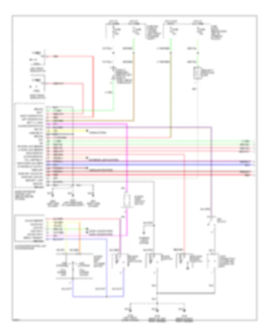
Anti-theft Wiring Diagram (1 of 2) for Nissan Quest XE 1998
List of elements for Anti-theft Wiring Diagram (1 of 2) for Nissan Quest XE 1998:
- Acc
- Back door sw
- Back door unlk sens
- Batt
- Batt (+) logic
- Circuit breaker 1 (behind left side of dash, above fuse block)
- Closed
- Door key lock sw
- Door key unlock sw
- Door locks system
- Exterior lights system
- Full stroke lock
- Full stroke unlock
- Fuse 10a
- Fuse 7.5a
- Fuse a 30a
- Fuse and fusible link box (left front of engine compt)
- Fuse block (behind dash, left of steering column)
- G100 (front of left front fender)
- G102 (left front shock tower)
- G105 (rear of right front fender)
- G201 (right side of dash)
- G202 (left side of dash)
- G404 (left rear side of luggage compt)
- Ground
- Headlamp
- Headlights system
- Hood sw
- Hood switch
- Horn relay
- Horns system
- Hot at all times
- Hot in acc or on
- Ign
- Interior lights system
- Joint connector 2 (in fuse and fusible link box)
- Key sw
- Key switch
- Left door switch
- Left front door switch
- Lf door lock sensor
- Lock input
- Lock sw
- Locked
- Mid stroke
- Open
- Red
- Ref gnd
- Rf door lock sensor
- Right door switch
- Right front door switch
- Security indicator lamp
- Security lamp
- Serial transmit
- Sliding door actuator
- Sliding door contact switch
- Sliding door control unit (in sliding door)
- Sliding door key cylinder switch
- Sliding door status
- Sliding door sw
- Sliding door switch
- Smart entrance control unit (behind center of dash)
- Starter cut output
- Tail lamp relay
- Unlock input
- Unlock sensor
- Unlock sw
- Unlocked
Anti-theft Wiring Diagram (2 of 2) for Nissan Quest XE 1998
List of elements for Anti-theft Wiring Diagram (2 of 2) for Nissan Quest XE 1998:
- Acc
- Back door key cylinder switch (w/ glass hatch)
- Back door key cylinder switch (w/o glass hatch)
- Back door latch switch (w/o glass hatch)
- Back door latch switch and lock actuator (w/ glass hatch)
- Back door lock actuator (w/o glass hatch)
- Closed
- Full stroke lock
- Full stroke unlock
- Fuse 10a
- Fuse 7.5a
- Fuse and fusible link box (left front of engine compt)
- Fuse block (behind dash, left of steering column)
- G100 (front of left front fender)
- G102 (left front shock tower)
- G105 (rear of right front fender)
- G201 (right side of dash)
- G202 (left side of dash)
- G404 (left rear side of luggage compt)
- G999 (left rear "d" pillar)
- Hot at all times
- Hot in on or start
- Ignition switch
- Inhibitor relay (in fuse and fusible link box)
- Inhibitor switch
- Left front door key cylinder switch
- Left front door lock actuator
- Locked
- Mid stroke
- Off
- Open
- Red
- Right front door key cylinder switch
- Right front door lock actuator
- Start
- Starter motor
- Theft warning relay (in relay box)
- Unlocked
BODY COMPUTER
Body Computer Wiring Diagrams for Nissan Quest XE 1998
List of elements for Body Computer Wiring Diagrams for Nissan Quest XE 1998:
- Accessory
- Antenna
- Antenna signal
- Anti-theft system
- Back door latch switch
- Back door lock actuator
- Back dr ul out
- Battery
- Bk door latch sw
- Bk dr unlck sens
- Circuit breaker (behind (left side of dash, above fuse panel)
- Dash, left of steering column)
- Defogger system
- Door locks system
- Door unlock sensor
- Full
- Fuse 10a
- Fuse 7.5a
- Fuse a 30a
- Fuse and fusible link box (left front of engine compt)
- Fuse block (behind
- G100 (front of left front fender)
- G102 (left front shock tower)
- G105 (rear of right front fender)
- G201 (right side of dash)
- G202 (left side of dash)
- G404 (left rear side of luggage compt)
- G999 (left rear "d" pillar)
- Ground
- Headlamp
- Hood switch
- Horn relay
- Horns system
- Hot at all times
- Hot in acc or on
- Hot in on or start
- Ignition switch
- Ill cont sw dark
- Ill cont sw light
- Ill control out
- Interior lights system
- J/c 2 (in fuse & fusible linl box)
- Key cyl lock sw
- Key cyl unlck sw
- Key switch
- L frnt dr ul out
- L unlock sensor
- Left door sw
- Left front door key cylinder switch
- Left front door lock actuator
- Left front door switch
- Lock in
- Lock out
- Lock signal
- Power windows system
- Pwr wind rly cont
- R frnt dr ul out
- R unlock sensor
- Rear defog out
- Rear defog sw
- Red
- Ref gnd
- Right door sw
- Right front door key cylinder switch
- Right front door lock actuator
- Right front door switch
- Room lamp zone a
- Room lamp zone b
- Room lamp zone c
- Seat belt sw
- Security lamp
- Serial trnsmit
- Sl dr ul sens
- Slide door status
- Sliding door actuator
- Sliding door contact switch
- Sliding door control unit (in sliding door)
- Sliding door sw
- Sliding door switch
- Smart entrance control unit (behind center of dash)
- Starter cutout
- Tail lamp relay
- Unlock in
- Unlock sensor
- Unlock signal
- Unlock switch
- Warn chime out
- Warning systems
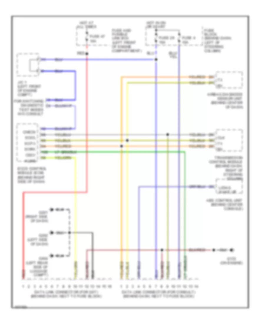
COMPUTER DATA LINES
Computer Data Lines for Nissan Quest XE 1998
List of elements for Computer Data Lines for Nissan Quest XE 1998:
- Abs control unit (behind center console)
- Airbag diagnosis sensor unit (behind center of dash)
- Cdcv
- Check
- Clk
- Data link connector (for consult) (behind dash, next to fuse block)
- Data link connector (for gst) (behind dash, next to fuse block)
- Eccs control module (ecm) (behind right side of dash)
- For switching diagnostic test modes w/o consult
- Fuse 29 10a
- Fuse 4 10a
- Fuse 47 10a
- Fuse and fusible link box (left front of engine compartment)
- Fuse block (behind dash, left of steering column)
- G133 (on engine)
- G201 (right side of dash)
- G202 (left side of dash)
- G404 (left rear side of luggage compt)
- Hot at all times
- Hot in on or start
- J/c 1 (left front of engine compt)
- Kline
- L/diag wake up
- Red
- Scicl
- Scirx
- Scitx
- Transmission control module (behind dash, right of steering column)
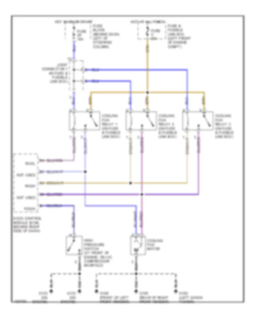
COOLING FAN
Cooling Fan Wiring Diagram for Nissan Quest XE 1998
List of elements for Cooling Fan Wiring Diagram for Nissan Quest XE 1998:
- Cooling fan motor
- Cooling fan relay 1 (on fuse & fusible link box)
- Cooling fan relay 2 (on fuse & fusible link box)
- Cooling fan relay 3 (on fuse & fusible link box)
- Eccs control module (ecm) (behind right side of dash)
- Fuse & fusible link box (left front of engine compt)
- Fuse 10a
- Fuse block (behind dash, left of steering column)
- Fuse c 65a
- G100 (front of left front fender)
- G102 (left shock tower)
- G105 (rear of right front fender)
- G133 (on engine)
- High pressure switch (at front of engine, on a/c compressor manifold)
- Hot at all times
- Hot in on or start
- Joint connector 1 (in fuse & fusible link box)
- Not used
- Pdsw
- Radh
- Radl
CRUISE CONTROL
Cruise Control Wiring Diagram for Nissan Quest XE 1998
List of elements for Cruise Control Wiring Diagram for Nissan Quest XE 1998:
- (fuse & fusible link box)
- (left side of dash) g202
- Above brake pedal)
- Air valve
- Air valve solenoid
- Ascd brake switch (on bracket,
- Ascd control unit (behind center
- Ascd hold relay (fuse & fusible link box)
- Ascd main switch
- Ascd pump (right side of engine compt)
- Ascd steering switch
- Brake nc sw
- Brake no sw
- Cancel
- Cruise ind.
- Cruise lamp
- Cruise switch
- Electric speed- ometer
- Exterior lights system
- Fuse 22 15a
- Fuse 29 10a
- Fuse 30 10a
- Fuse 44 15a
- Fuse block (left side of dash)
- G102 (left front shock tower)
- G202 (left side of dash)
- G206 (center rear of dash)
- Ground
- Horn relay (fuse & fusible link box)
- Horns system
- Hot at all times
- Hot in on or start
- Inhibitor relay (fuse & fusible link box)
- Inhibitor switch (left side of transaxle)
- Instrument cluster
- Interior lights system
- J/c 1
- J/c 1 (in fuse & fusible link box)
- J/c 3 (left side of dash)
- Main switch
- Nca
- Od cancel
- Od cut signal
- Of dash)
- Off
- Pnk
- Pump power
- Release valve
- Release valve solenoid
- Res/acc sw
- Resume/ accelerate
- Set/coast
- Set/coast sw
- Spiral cable
- Stop lamp switch (on bracket, above brake pedal)
- Theft warning relay (relay box)
- Transmission control module (behind dash, right of steering column)
- Transmission system
- Vacuum motor
- Vehicle speed sensor (on transaxle)
- Vss
- W/ theft
- W/o theft
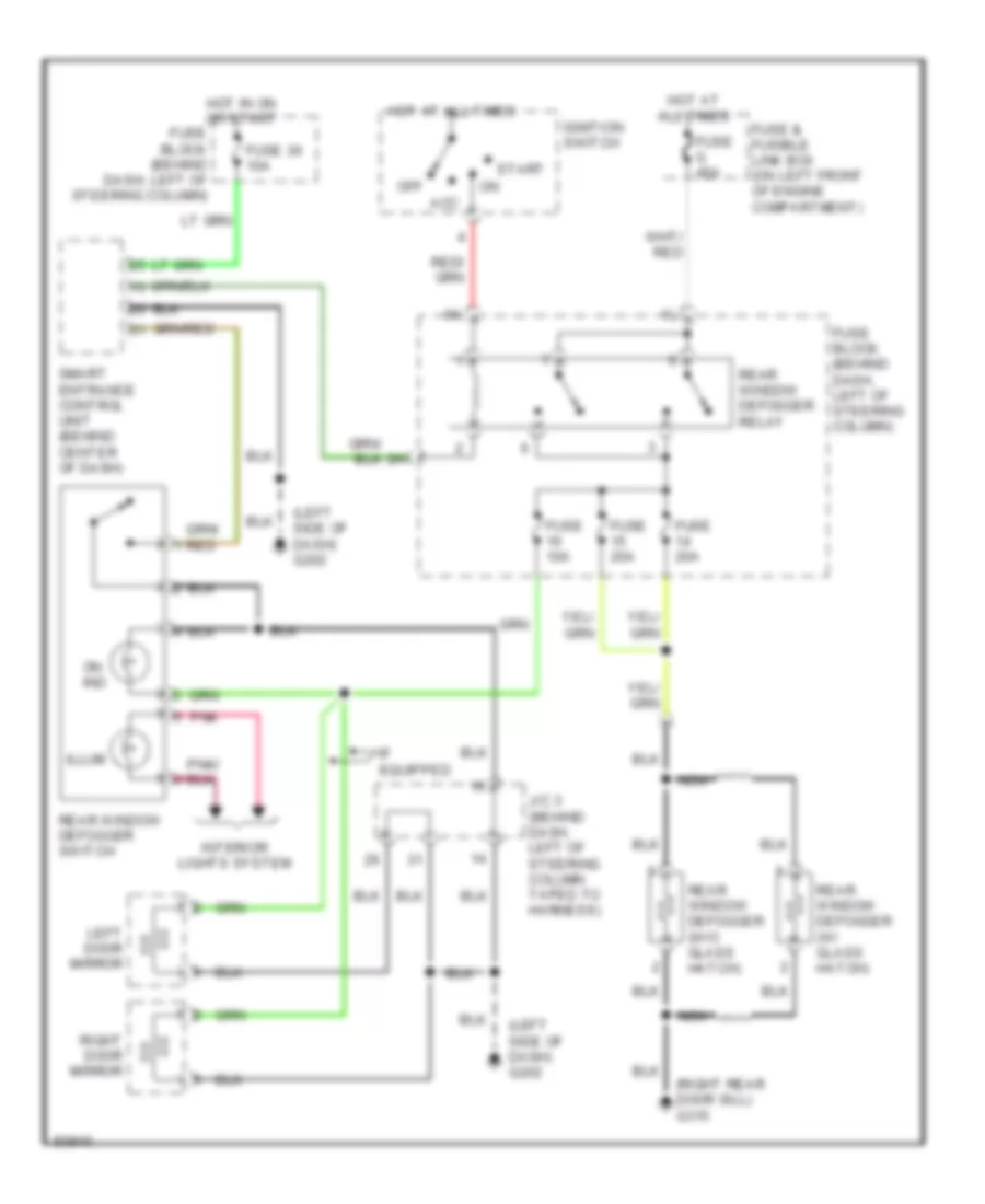
DEFOGGERS
Defogger Wiring Diagram for Nissan Quest XE 1998
List of elements for Defogger Wiring Diagram for Nissan Quest XE 1998:
- (left side of dash) g202
- (right rear door sill) g315
- Acc
- Fuse & fusible link box (on left front of engine compartment)
- Fuse 10a
- Fuse 20a
- Fuse 30 10a
- Fuse block (behind dash, left of steering column)
- Fuse g 45a
- Hot at all times
- Hot in on or start
- If equipped
- Ignition switch
- Illum
- Interior lights system
- J/c 3 (behind dash, left of steering column taped to harness)
- Left door mirror
- Nca
- Off
- On ind
- Pnk
- Rear window defogger (w/ glass hatch)
- Rear window defogger (w/o glass hatch)
- Rear window defogger relay
- Rear window defogger switch
- Right door mirror
- Smart entrance control unit (behind center of dash)
- Start
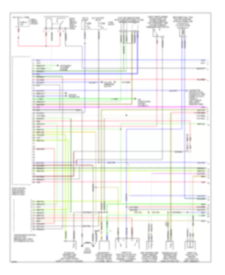
ENGINE PERFORMANCE
3.0L
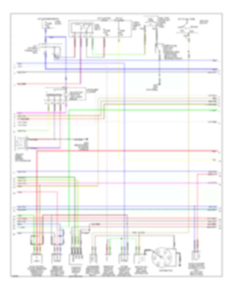
3.0L, Engine Performance Wiring Diagrams (1 of 3) for Nissan Quest XE 1998
List of elements for 3.0L, Engine Performance Wiring Diagrams (1 of 3) for Nissan Quest XE 1998:
- (between fuel tank & evap canister, on evap purge line) vacuum cut valve by-pass valve (cali)
- (on throttle body assembly)
- (right rear corner of eng compt, on power steering high pressure tube) power steering pressure (psp) switch
- (top left rear of eng) evap canister purge volume control valve (cali)
- A/c high pressure switch
- Air conditioning system (a/c relay)
- Assembly, integral to tp sensor)
- Compt, in air duct housing)
- Connector for switching diagnostic test modes without consult (left side of eng compt, near battery)
- Cooling fan relays
- Crankshaft position sensor (on transaxle housing, facing
- Eccs control module (ecm) (behind right side of dash)
- Eccs relay (behind right side of dash)
- Egr temperature (egrt) sensor (top right rear of eng, on base of egr valve)
- Engine coolant temperature (ect) sensor (front of eng,
- Flywheel teeth)
- Fuse & fusible link box
- Fuse 10a
- Fuse 47 10a
- Fuse 7.5a
- Fuse block
- G134 (top of engine)
- Hot at all times
- Hot in start
- Hot in start or on
- Instrument cluster system
- Intake air temperature (iat) sensor (left front of eng
- Nca
- Near distributor)
- Pnk
- Red
- Throttle position (tp) sensor
- Throttle position (tp) switch (on throttle body
- Transmission control module (tcm) (behind dash, right of steering column)
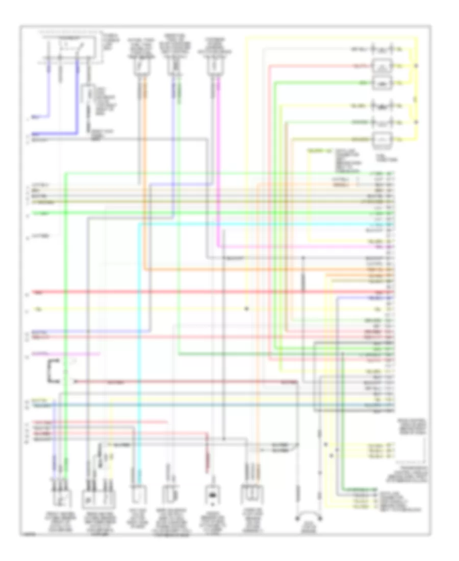
3.0L, Engine Performance Wiring Diagrams (2 of 3) for Nissan Quest XE 1998
List of elements for 3.0L, Engine Performance Wiring Diagrams (2 of 3) for Nissan Quest XE 1998:
- (left kick panel)
- Absolute pressure sensor (cali) (on left side of firewall)
- Acc
- Camshaft position
- Condenser (behind right side of dash, next to eccs relay)
- Distributor
- Evap canister purge control solenoid valve (cali) (on top left rear of eng)
- Evap control system pressure sensor (cali) (near evap canister)
- Fuel pump
- Fuel pump relay
- Fuel tank gauge unit (inside fuel tank)
- Fuse & fusible link box
- Fuse 10a
- Fuse 15a
- Fuse block
- G200
- G302 (behind front of center console)
- Hot at all times
- Hot in start or on
- Hot in start or run
- Ignitiion switch
- Ignition coil (front of eng, near distributor)
- Inertia fuel shutoff switch (near driver's door frame, below hood release handle)
- Instrument cluster
- J/c 1 (in fuse & fusible link box)
- Lock
- Malfunction indicator lamp "check engine"
- Nca
- Nca gnd
- Nca out
- Nca pwr in
- Nca ref
- Pnk
- Power transistor (front of eng, near distributor)
- Red
- Resistor (on right front of eng, near distributor)
- Run
- Sensor (in distributor)
- Speedometer
- Start
- Vehicle speed sensor (on transaxle)
3.0L, Engine Performance Wiring Diagrams (3 of 3) for Nissan Quest XE 1998
List of elements for 3.0L, Engine Performance Wiring Diagrams (3 of 3) for Nissan Quest XE 1998:
- (in fuel tank) fuel tank gauge unit (tank fuel temp sensor)
- (near fuel tank, on evap canister) evap canister vent control valve (cali)
- (right kick panel) g203
- (top rear of eng) map/baro switch solenoid valve (cali)
- Data link connector (for consult) (behind dash,
- Data link connector (gst) (behind dash next to fuse block)
- Eccs control module (ecm) (behind right side of dash)
- Egrc solenoid valve (cali) egr valve & evap canister purge control valve (except cali) (top rear of eng)
- Ficd relay
- Front heated oxygen sensor (front of catalytic converter)
- Fuel injectors
- Fuse & fusible link box
- G134 (top of engine)
- Iacv- ficd solenoid valve (top right front of eng)
- Iacv-aac valve (on top right side of eng)
- Knock sensor (ks) (top of eng, attached to cylinder clock)
- Mass air flow (maf) sensor (on air intake assembly)
- Nca
- Next to fuse block)
- Rear heated oxygen sensor (between rear catalytic converter & muffler)
- Red
- Transmission control module (behind dash, right of steering column)
EXTERIOR LIGHTS
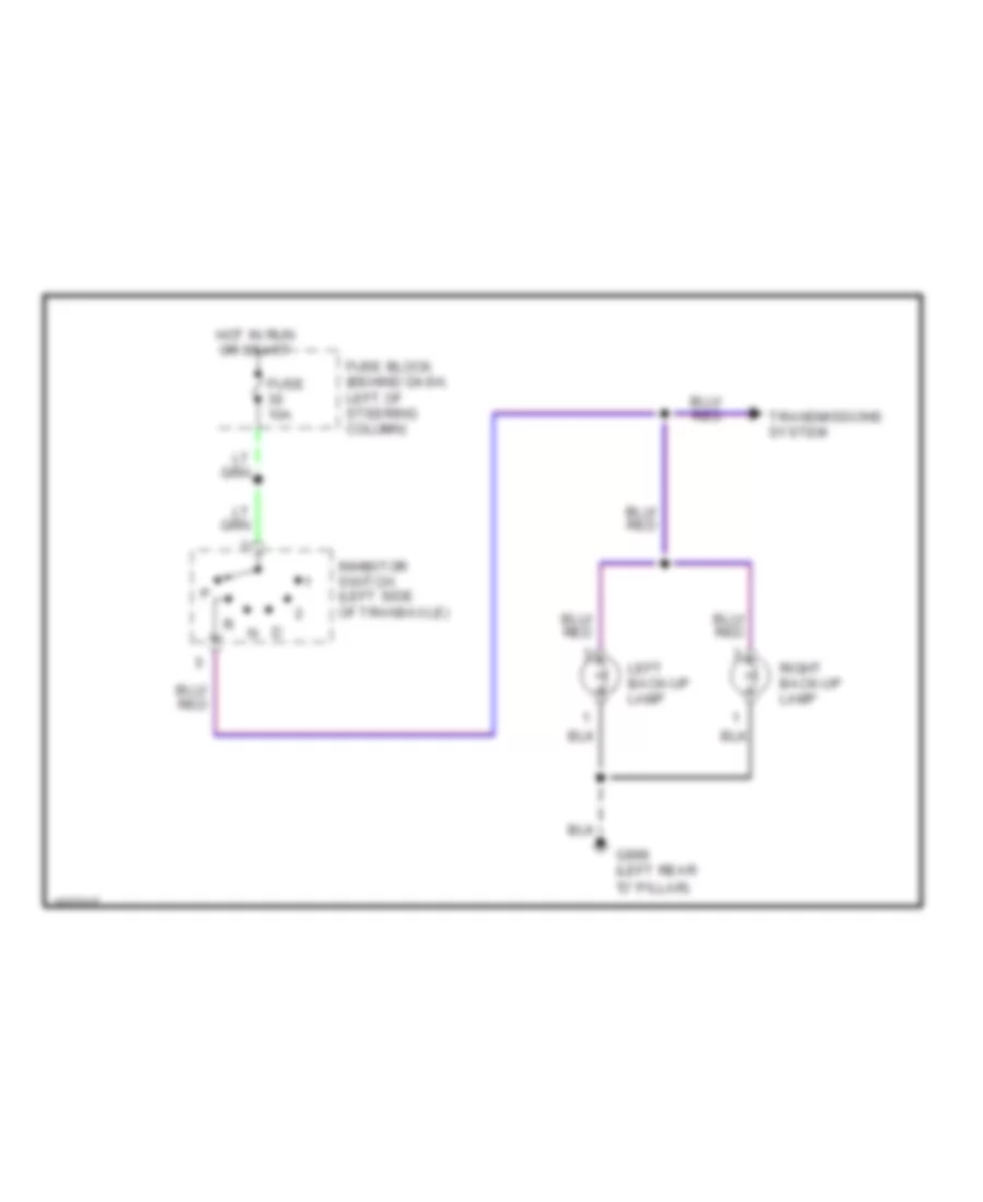
Back-up Lamps Wiring Diagram for Nissan Quest XE 1998
List of elements for Back-up Lamps Wiring Diagram for Nissan Quest XE 1998:
- "d" pillar)
- Fuse 10a
- Fuse block (behind dash, left of steering column)
- G999 (left rear
- Hot in run or start
- Inhibitor switch (left side of transaxle)
- Left back-up lamp
- Right back-up lamp
- Transmissions system
Exterior Lamps Wiring Diagram (1 of 2) for Nissan Quest XE 1998
List of elements for Exterior Lamps Wiring Diagram (1 of 2) for Nissan Quest XE 1998:
- "d" pillar)
- Cluster
- Combination flasher unit (behind left kick panel)
- Combination switch (turn signal switch)
- Fuse 23 10a
- Fuse 27 10a
- Fuse block (behind dash, left of steering column)
- G100 (front of left front fender)
- G102 (left front shock tower)
- G105 (rear of right front fender)
- G201 (right side of dash)
- G202 (left side of dash)
- G404 (left rear side of luggage compt)
- G998 (right rear
- G999 (left rear
- Ground
- Hazard switch
- Hot at all times
- Hot in start or run
- Illumination lamp
- Instrument
- Interior lights system
- J/c 3 (behind dash, left of column, taped to harness)
- Left
- Left front turn signal lamp
- Left rear combination lamp
- Left turn ind
- M28
- Off
- Out
- Pnk
- Power
- Right
- Right front turn signal lamp
- Right rear combination lamp
- Right turn ind
- Stop
- Tail
- Turn
Exterior Lamps Wiring Diagram (2 of 2) for Nissan Quest XE 1998
List of elements for Exterior Lamps Wiring Diagram (2 of 2) for Nissan Quest XE 1998:
- "d" pillar)
- (behind trim panel, above left rear wheel)
- 1st
- 2nd
- Anti-lock brake system
- Bat
- Combin- ation switch (corner- ing lamp switch)
- Cruise control system
- Fuse 10a
- Fuse 15a
- Fuse and fusible link box (left front of engine compt)
- Fuse block (behind dash, left of steering column)
- Fuse e 100a
- Fuse f 120a
- G100 (front of left front fender)
- G102 (left front shock tower)
- G105 (rear of right front fender)
- G201 (right side of dash)
- G202 (left side of dash)
- G404 (left rear side of luggage compt)
- G998 (right rear
- G999 (left rear
- Ground
- High mounted stop lamp
- Hot at all times
- J/c 2 (in fuse and fusible link box)
- J/c 3 (behind dash, left of column, taped to harness)
- J/c 3 (left side of dash)
- L stop
- L stop/turn
- Left front com- bination lamp
- Left front side marker lamp
- Left rear side marker lamp
- Left right
- Left turn
- License lamp
- Lighting switch
- Off
- Pnk
- R stop
- R stop/turn
- Right front com- bination lamp
- Right front side marker lamp
- Right rear side marker lamp
- Right turn
- Smart entrance control unit (behind center of dash)
- Stop
- Stop lamp switch (above brake pedal)
- Tail
- Tail lamp relay
- Tail lamp rly
- Trailer
- Trailer tow control unit
- Turn
- W/ anti-theft
- W/ trailer option
GROUND DISTRIBUTION
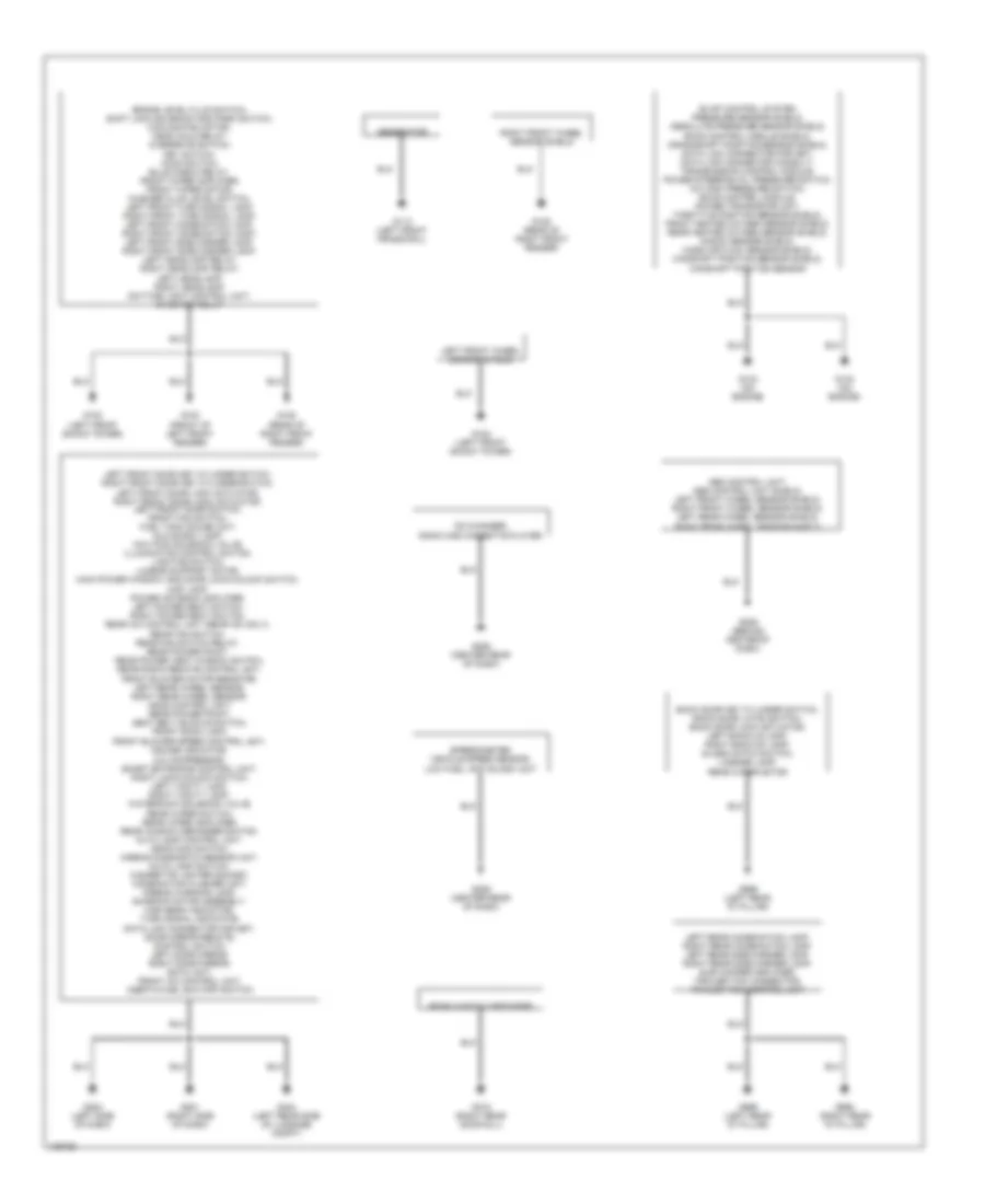
Ground Distribution Wiring Diagram for Nissan Quest XE 1998
List of elements for Ground Distribution Wiring Diagram for Nissan Quest XE 1998:
- Abs control unit, abs control unit shield, left front wheel sensor shield, right front wheel sensor shield, left rear wheel sensor shield, right rear wheel sensor shield
- Back door key cylinder switch, back door latch switch, back door lock actuator, left back-up lamp, right back-up lamp, glass hatch switch, license lamp, rear wiper motor
- Brake level fluid switch, shift lock solenoid and park switch, cooling fan motor, ascd hold relay, overdrive switch, key switch, hood switch, bulb check relay, front wiper amplifier, front wiper motor, washer fluid level switch, left front turn signal lamp, right front turn signal lamp, left front combination lamp, right front combination lamp, left front side marker lamp, right front side marker lamp, left headlamp relay, right headlamp relay, left headlamp, right headlamp, daytime light control unit, inhibitor relay
- Cd changer, radio and cassette player
- Evap control system pressure sensor shield, absolute pressure sensor shield, eccs control module shield, crankshaft position sensor shield, data link connector for gst, data link connector consult, transmission control module, power steering oil pressure switch, a/c high pressure switch, eccs control module, power transistor unit, throttle position sensor shield, front heated oxygen sensor shield, rear heated oxygen sensor shield, knock sensor shield, mass air flow sensor shield, camshaft position sensor shield, camshaft position sensor
- Front blower speed control unit, cruise indicator, a/c compressor, smart entrance control unit, right lock/unlock switch, left vanity lamp, right vanity lamp, watercock solenoid valve, rear wiper switch, rear wiper amplifier, rear window defogger switch, auto lamp control unit, ascd main switch, airbag diagnostic sensor unit, auto lamp switch, cigarette lighter socket, combination flasher unit, airbag warning lamp, sunroof motor assembly, high beam indicator, turn signal indicator, data link connector for gst, door mirror remote, control switch, left door mirror, right door mirror, eatc unit, front a/c control unit, inertia fuel shutoff switch
- G100 (front of left front fender)
- G102 (left front shock tower)
- G105 (rear of right front fender)
- G113 (left front frame rail)
- G133 (on engine)
- G201 (right side of dash)
- G202 (left side of dash)
- G206 (behind center of dash)
- G206 (center rear of dash)
- G315 (right rear door sill)
- G404 (left rear side of luggage compt)
- G998 (right rear "d" pillar)
- G999 (left rear "d" pillar)
- Generator
- Left front door key cylinder switch, right front door key cylinder switch, left front door lock actuator, right front door lock actuator, left front door switch, front fan switch, fuel tank gauge unit, glove box lamp, iacv-ficd solenoid valve, illumination control switch, lighting switch, lumbar support motor, main power window and door lock/unlock switch, map lamp, power antenna amplifier, left power seat switch, right power seat switch, rear a/c control unit (rear a/c only), rear fan switch, rear fan switch relay, rear power point, rear power vent window switch, rear radio remote control unit, front blower motor resistor, left rear wheel sensor, right rear wheel sensor, ascd control unit, rear power point, seat belt buckle switch, front room lamp,
- Left front wheel sensor shield
- Left rear combination lamp, right rear combination lamp, left rear side marker lamp, right rear side marker lamp, sub woofer amplifier, trailer tow connector, trailer tow control unit
- Rear window defogger
- Right front wheel sensor shield
- Speedometer, vehicle speed sensor, low fuel/ anti-slosh unit
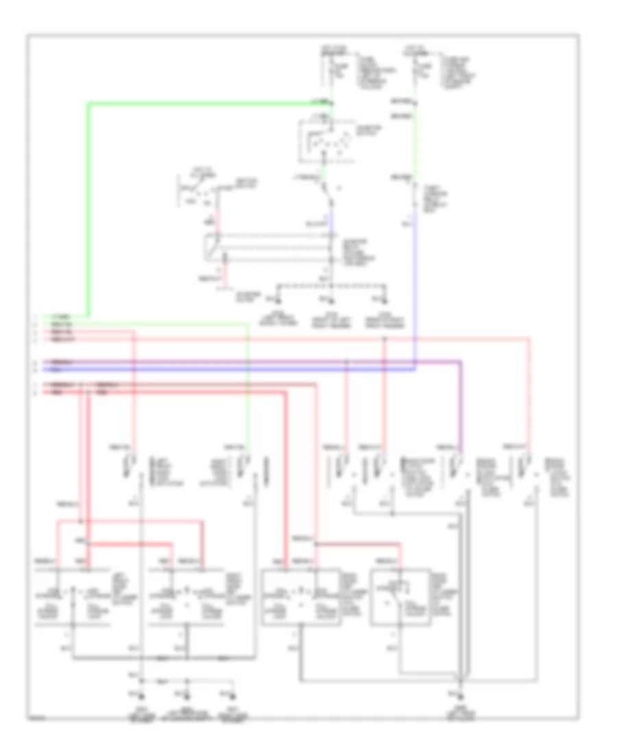
HEADLIGHTS
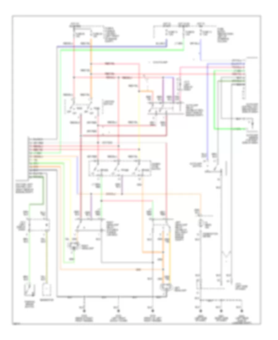
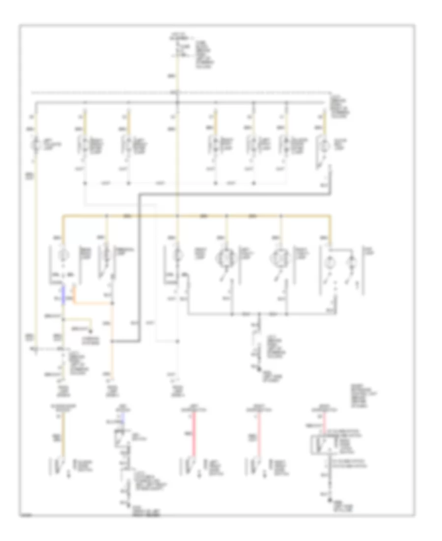
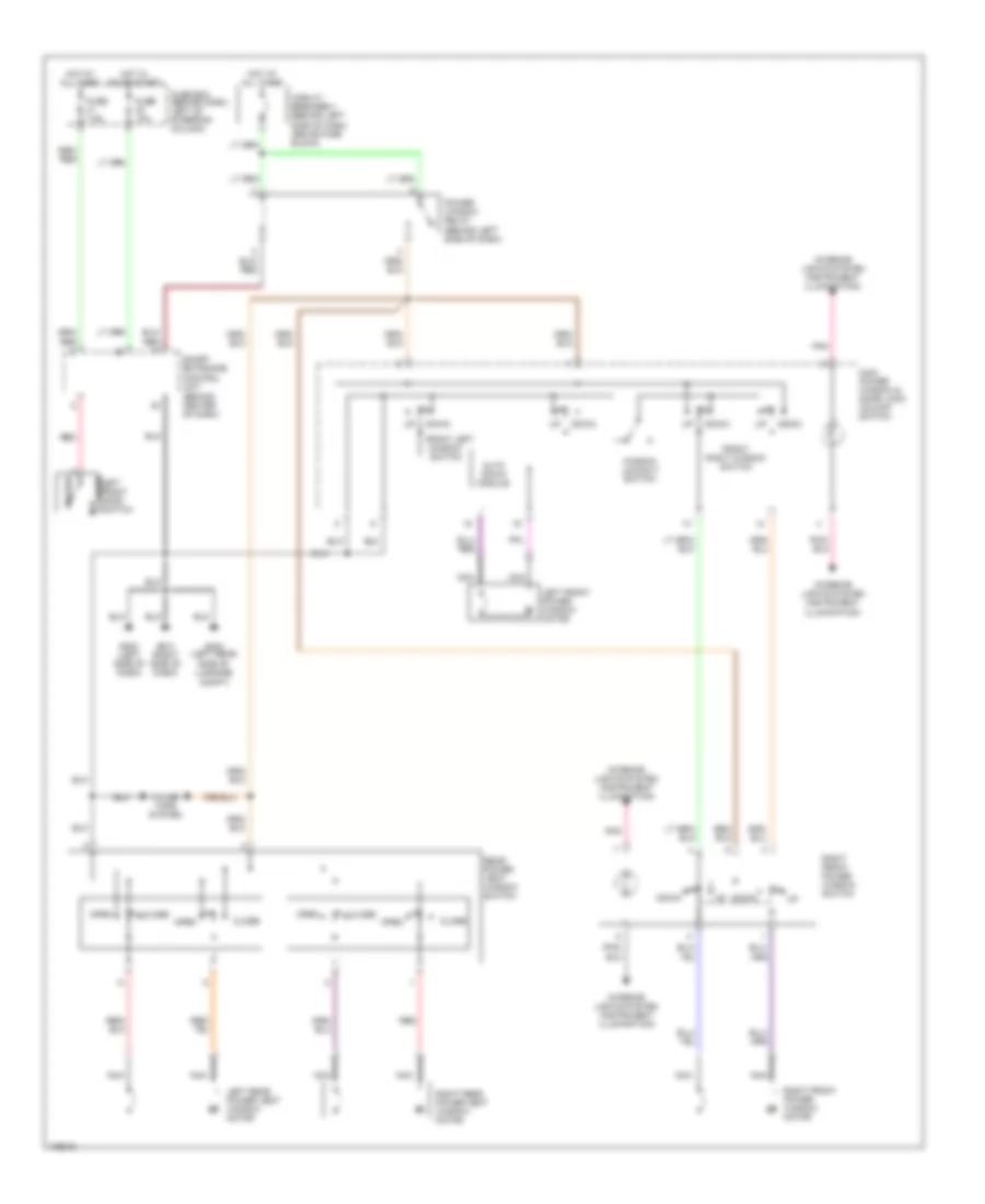
Headlight Wiring Diagram, with DRL for Nissan Quest XE 1998
List of elements for Headlight Wiring Diagram, with DRL for Nissan Quest XE 1998:
- 1st
- 2nd
- Autolamp control unit (behind right side of dash)
- Autolamp relay (on relay box, right side of engine compt)
- Autolamp sensor (top right side of dash)
- Autolamp switch
- Combin- ation switch
- Combination meter
- Daytime light control unit (right rear of engine compt)
- Fuse & fusible link box (left front of engine compt)
- Fuse 12 7.5a
- Fuse 13 7.5a
- Fuse 30 10a
- Fuse 49 15a
- Fuse 50 15a
- Fuse block (behind dash, left of steering column)
- G100 (front of left front fender)
- G102 (left front shock tower)
- G105 (rear of right front fender)
- G201 (right side of dash)
- G202 (left side of dash)
- G404 (left rear side of luggage compt)
- Generator
- Hi beam ind
- Hot at all times
- Hot in on
- Hot in on or start
- Hot in start
- J/c 3 (left side of dash)
- J/c 4 (left side of dash)
- Left headlamp
- Left headlamp relay (on relay box, right side of engine compt)
- Lighting switch
- Off
- Parking brake switch
- Pass
- Right headlamp
- Right headlamp relay (in fuse & fusible link box)
- W/autolamp
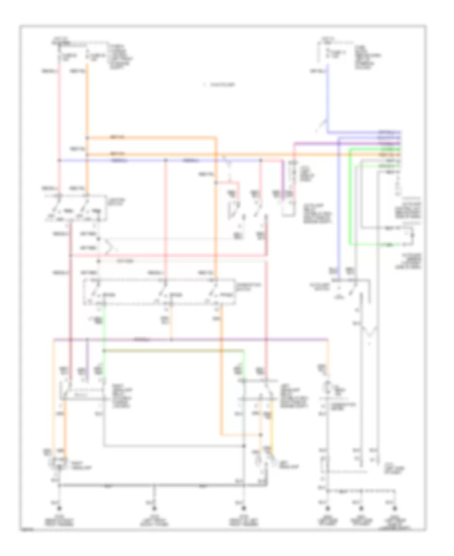
Headlight Wiring Diagram, without DRL for Nissan Quest XE 1998
List of elements for Headlight Wiring Diagram, without DRL for Nissan Quest XE 1998:
- 1st
- 2nd
- Autolamp control unit (behind right side of dash)
- Autolamp relay (on relay box, right side of engine compt)
- Autolamp sensor (top right side of dash)
- Autolamp switch
- Combination meter
- Combination switch
- Fuse & fusible link box (left front of engine compt)
- Fuse 13 7.5a
- Fuse 49 15a
- Fuse 50 15a
- Fuse block (behind dash, left of steering column)
- G100 (front of left front fender)
- G102 (left front shock tower)
- G105 (rear of right front fender)
- G201 (right side of dash)
- G202 (left side of dash)
- G404 (left rear side of luggage compt)
- Hi beam ind
- Hot at all times
- Hot in on
- J/c 3 (left side of dash)
- Left headlamp
- Left headlamp relay (on relay box, right side of engine compt)
- Lighting switch
- Off
- Pass
- Right headlamp
- Right headlamp relay (in fuse & fusible link box)
- W/autolamp
HORN
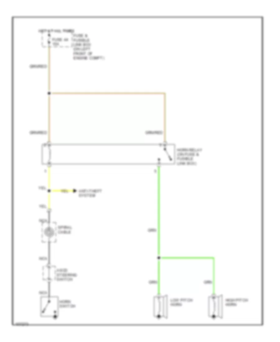
Horn Wiring Diagram for Nissan Quest XE 1998
List of elements for Horn Wiring Diagram for Nissan Quest XE 1998:
- Anti-theft system
- Ascd steering switch
- Fuse & fusible link box (on left front of engine compt)
- Fuse 44 15a
- High pitch horn
- Horn relay (on fuse & fusible link box)
- Horn switch
- Hot at all times
- Low pitch horn
- Nca
- Spiral cable
INSTRUMENT CLUSTER
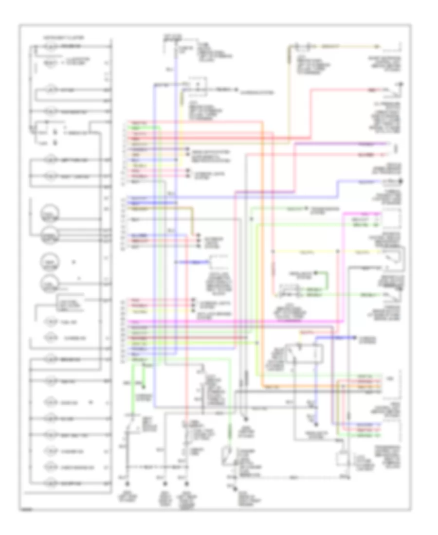
Instrument Cluster Wiring Diagram for Nissan Quest XE 1998
List of elements for Instrument Cluster Wiring Diagram for Nissan Quest XE 1998:
- (1996-97) (1998)
- (1998) (1996-97)
- A/t ind
- Abs ind
- Airbag ind
- Anti-lock brakes system
- Ascd control unit (behind center of dash)
- Brake fluid level switch (in reservoir)
- Brake ind
- Bulb check relay (on fuse & fusible link box)
- Charge ind
- Charging system
- Check engine ind
- Cruise ind
- Data link connector (for consult) (behind dash, next to fuse block)
- Door ind
- Ecm eccs control module (behind right side of dash)
- Exterior lights system
- Fuel gauge
- Fuel ind
- Fuel tank gauge unit (in tank)
- Fuse 29 10a
- Fuse block (behind dash, left of steering column)
- G105 (rear of right front fender)
- G201 (right side of dash)
- G202 (left side of dash)
- G206 (center of dash)
- G404 (left rear side of luggage compt)
- Headlights system
- High beam ind
- Hot in on or start
- Illumination (x4 bulbs)
- Instrument cluster
- Interior lights system
- J/c-2 (in fuse & fusible link box)
- J/c-3 (behind dash, left of steering column, taped to harness)
- J/c-4 (behind dash, left of steering column, taped to harness)
- Left turn ind
- Low fuel/ anti slosh unit
- O/d off ind
- Oil ind
- Oil pressure switch (1996-97 right side of engine, 1998 at lower left front of engine, at base of oil filter)
- Parking brake switch (at base of park brake lever)
- Pnk
- Red
- Right turn ind
- Seat belt buckle switch
- Seat belt ind
- Smart entrance control unit (behind center of dash)
- Speed- ometer
- Tach- ometer
- Temp. gauge
- Thermal transmitter (top right side of engine)
- Transmission control unit (behind dash, right of steering column)
- Transmissions system
- Vehicle speed sensor (on transaxle)
- Vss
- Warning system
- Warning systems
- Washer fluid level switch (on washer fluid reservoir)
- Washer ind
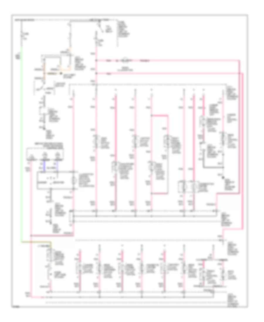
INTERIOR LIGHTS
Courtesy Lamps Wiring Diagram for Nissan Quest XE 1998
List of elements for Courtesy Lamps Wiring Diagram for Nissan Quest XE 1998:
- (w/ glass hatch)
- (w/ glass hatch) (w/o glass hatch)
- (w/o glass hatch)
- Back door latch switch
- Back door switch
- Closed
- Door
- Front room lamp
- Fuse 15a
- Fuse block (behind dash, left of steering column)
- G100 (front of left front fender)
- G202 (left side of dash)
- G999 (left side "b" pillar)
- Glove box lamp
- Hot at all times
- J/c 2 (in fuse & fusible link box, left front of eng compt)
- J/c 3 (behind dash, left of steering column)
- J/c 5 (behind dash, right of steering column)
- Key switch
- Left door switch
- Left foot lamp
- Left front door switch
- Left front step lamp
- Left tailgate lamp
- Left vanity lamp
- Map lamp
- Nca
- Off
- Open
- Personal lamp
- Rear room lamp
- Red
- Right door switch
- Right foot lamp
- Right front door switch
- Right front step lamp
- Right vanity lamp
- Room lamp zone a
- Room lamp zone b
- Room lamp zone c
- Sliding door step lamp
- Sliding door switch
- Smart entrance control unit (behind center of dash)
- Warning systems
Instrument Illumination Wiring Diagram for Nissan Quest XE 1998
List of elements for Instrument Illumination Wiring Diagram for Nissan Quest XE 1998:
- (behind center of dash) smart entrance control unit
- Anti-theft system
- Ascd main switch (illumi- nation)
- Ashtray (illumi- nation)
- Brighter
- Cigarette lighter (illumi- nation)
- Combination meter (illumi- nation)
- Darker
- Diode (left side of dash)
- Door remote control switch (illumi- nation)
- Eatc unit (illumi- nation)
- Front a/c control unit (illumi- nation)
- Fuse 10a
- Fuse 7.5a
- Fuse block (behind dash, left of steering column)
- G202 (left side of dash)
- G405 (rear of left quarter p[anel)
- Hazard switch (illumi- nation)
- Head
- Hot at all times
- Hot in acc or on
- Ill ctrl output
- Ill ctrl sw darker
- Ill ctrl sw lighter
- Illumination control switch & autolamp switch (illumination)
- J/c 3 (behind dash, left of steering column)
- J/c 4 (behind dash, left of steering column)
- J/c 5 (behind dash, right of steering column)
- Lighting switch
- Lighting switch (illumi- nation)
- Main power window & door lock/ unlock switch (illumi- nation)
- Off
- Park
- Pnk
- Pnk/
- Radio (illumination)
- Rear a/c control unit (illumi- nation)
- Rear fan switch (front) (illumi- nation)
- Rear radio remote control unit (illumi- nation)
- Rear window defogger switch (illumi- nation)
- Rear wiper switch (illumi- nation)
- Right door lock/ unlock switch (illumi- nation)
- Right front power window switch (illumi- nation)
- Tail lamp relay
- W/eatc
- W/o eatc
- W/rear a/c control unit
- W/rear radio remote control unit
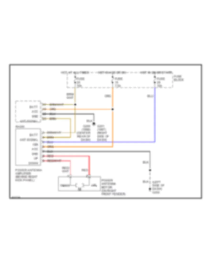
POWER ANTENNA
Power Antenna Wiring Diagram for Nissan Quest XE 1998
List of elements for Power Antenna Wiring Diagram for Nissan Quest XE 1998:
- Acc
- Ant-signal
- Batt
- Down
- Fuse 10a
- Fuse 7.5a
- Fuse block
- G201 (1997) (right side of dash)
- G206 (1998) (center rear of dash)
- Gnd
- Hot at all times
- Hot in acc or on
- Hot in on or start
- Ign
- Power antenna amplifier (behind right kick panel)
- Power antenna motor (on right front fender)
- Radi0
- Red
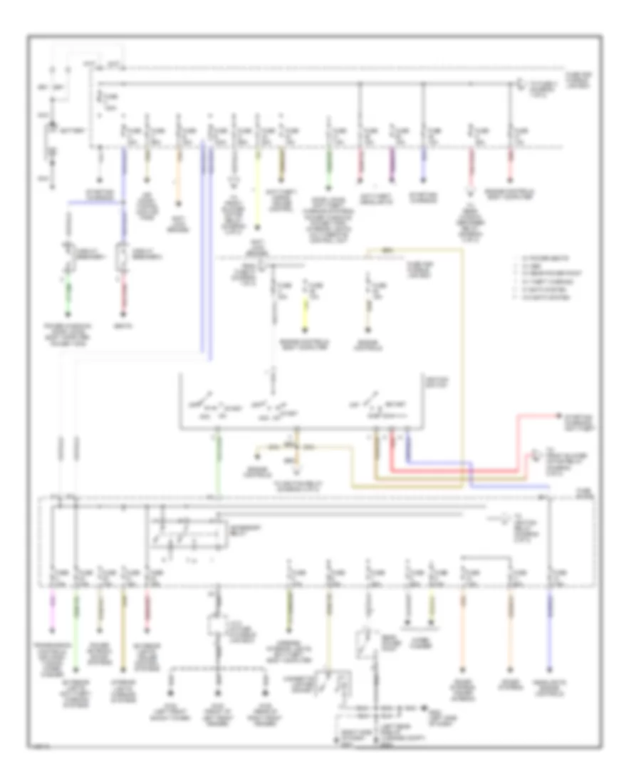
POWER DISTRIBUTION
Power Distribution Wiring Diagram (1 of 2) for Nissan Quest XE 1998
List of elements for Power Distribution Wiring Diagram (1 of 2) for Nissan Quest XE 1998:
- (left rear side of luggage compt) g404
- (right side of dash) g201
- Acc
- Accessory relay
- Air condi- tioning, cooling fans
- Anti- lock brakes
- Anti-theft, headlights
- Anti-theft, horns, cruise control
- Battery
- Cigarette lighter socket
- Circuit breaker-1
- Circuit breaker-2
- Door locks, anti-theft, warning systems, power windows, power tops, interior lights, multi-remote control unit
- Engine controls
- Engine controls, body computer
- Exterior lights, anti-theft, warning systems
- Exterior lights, cruise control systems
- From a fuse 47 (diagram 1 of 2)
- Fuse 10a
- Fuse 15a
- Fuse 20a
- Fuse 7.5a
- Fuse a 30a
- Fuse and fusible link box
- Fuse b 30a
- Fuse block
- Fuse c 65a
- Fuse d 65a
- Fuse e 100a
- Fuse f 120a
- Fuse g 45a
- Fuse h 30a
- G100 (front of left front fender)
- G102 (left front shock tower)
- G105 (rear of right front fender)
- G202 (left side of dash)
- Headlights, engine controls
- Ignition switch
- Interior lights, warning systems
- J/c 2 (in fuse & fusible link box)
- Mirrors, interior lights, anti-theft, body computer
- Nca
- Off
- Power antenna, sound systems
- Power windows, door locks body computer, power tops
- Rear power point
- Red
- Seats
- Sound systems
- Sound systems, power antenna
- Start
- Starting/ charging
- Starting/ charging, anti-theft
- To front blower motor relay (diagram 2 of 2)
- To fuse h (diagram 1 of 2)
- To ignition relay (diagram 2 of 2)
- To rear window defogger relay (diagram 2 of 2)
- Transmission controls, air condi- tioning, wiper/ washer
- W/ abs
- W/ eatc system
- W/ power seats
- W/ rear power point
- W/ theft warning
- W/o eatc system
- Wiper/ washer
Power Distribution Wiring Diagram (2 of 2) for Nissan Quest XE 1998
List of elements for Power Distribution Wiring Diagram (2 of 2) for Nissan Quest XE 1998:
- 1st
- 2nd
- Air conditioning
- Air conditioning, headlights
- Anti-theft, body computer
- Defogger
- Engine controls, transmission controls
- Exterior lights
- Exterior lights, anti-theft, body computer
- From accessory g
- From fuse d (diagram 1 of 2)
- From fuse g (diagram 1 of 2)
- From ignition switch (diagram 1 of 2)
- Front blower motor relay
- Fuse 10a
- Fuse 13 7.5a
- Fuse 14 20a
- Fuse 15 20a
- Fuse 16 10a
- Fuse 24 15a
- Fuse 25 15a
- Fuse 28 20a
- Fuse 31 20a
- Fuse 7.5a
- Fuse block
- G100 (front of left front fender)
- G102 (left front shock tower)
- G105 (rear of right front fender)
- G201 (right side of dash)
- G202 (left side of dash)
- G404 (left rear side of luggage compt)
- Headlights system
- Ignition relay
- Interior lights, body computer
- J/c 2 (in fuse & fusible link box)
- J/c 3 (behind dash, left of steering column, taped to harness)
- Light switch
- Mirrors, defogger
- Off
- Pnk
- Power tops, defogger, mirrors, interior lights, starting, engine controls, anti-theft, headlights, exterior lights, power windows, warning systems, anti-lock brakes, body computer
- Rear window defogger relay
- Relay (diagram 1 of 2)
- Tail lamp relay
- W/ abs
- W/ eatc system
- W/ power seats
- W/ rear power point
- W/ theft warning
- W/o eatc system
POWER DOOR LOCKS
Power Door Lock Wiring Diagram (1 of 2) for Nissan Quest XE 1998
List of elements for Power Door Lock Wiring Diagram (1 of 2) for Nissan Quest XE 1998:
- Acc
- Batt
- Batt (+) logic
- Bk door unlk sens
- Bk door unlock out
- Circuit breaker 1 (behind left side of dash, above fuse block)
- Closed
- Door key lock sw
- Door key unlock sw
- Full stroke lock
- Full stroke unlock
- Fuse 10a
- Fuse 7.5a
- Fuse a 30a
- Fuse and fusible link box (left front of engine compt)
- Fuse block (behind dash, left of steering column)
- G201 (right side of dash)
- G202 (left side of dash)
- G404 (left rear side of luggage compt)
- G404 (left rear side of trunk)
- Ground
- Hot at all times
- Hot in acc or on
- Hot in on or start
- Ign
- Key sw
- Left door switch
- Left front door switch
- Lf door lock sensor
- Lf door unlock out
- Lock input
- Lock out
- Lock sig
- Lock sw
- Locked
- Main power window & door lock/ unlock switch
- Mid stroke
- Open
- Red
- Ref gnd
- Rf door lock sensor
- Rf door unlock out
- Right door lock/ unlock switch
- Right door switch
- Right front door switch
- Serial transmit
- Sliding door actuator
- Sliding door contact switch
- Sliding door control unit (w/ anti-theft) (in sliding door)
- Sliding door key cylinder switch
- Sliding door status
- Sliding door sw
- Sliding door switch
- Smart entrance control unit (behind center of dash)
- Unlock input
- Unlock sensor
- Unlock sig
- Unlock sw
- Unlocked
- W/ anti-theft
Power Door Lock Wiring Diagram (2 of 2) for Nissan Quest XE 1998
List of elements for Power Door Lock Wiring Diagram (2 of 2) for Nissan Quest XE 1998:
- Back door key cylinder switch (w/ glass hatch)
- Back door key cylinder switch (w/o glass hatch)
- Back door lock actuator (w/o glass hatch)
- Full stroke lock
- Full stroke unlock
- G100 (front of left front fender)
- G102 (left front shock tower)
- G105 (rear of right front fender)
- G201 (right side of dash)
- G202 (left side of dash)
- G404 (left rear side of luggage compt)
- G999 (left rear "d"
- Joint connector 2 (in fuse and fusible link box)
- Key switch
- Left front door key cylinder switch
- Left front door lock actuator
- Locked
- Mid stroke
- Pillar)
- Red
- Right front door key cylinder switch
- Right front door lock actuator
- Unlocked
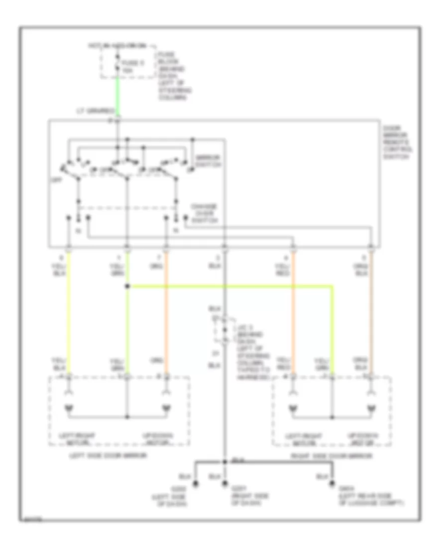
POWER MIRRORS
Power Mirror Wiring Diagram for Nissan Quest XE 1998
List of elements for Power Mirror Wiring Diagram for Nissan Quest XE 1998:
- Change over switch
- Door mirror remote control switch
- Fuse 5 10a
- Fuse block (behind dash, left of steering column)
- G201 (right side of dash)
- G202 (left side of dash)
- G404 (left rear side of luggage compt)
- Hot in acc or on
- J/c 3 (behind dash, left of steering column, taped to harness)
- Left side door mirror
- Left/right motor
- Mirror switch
- Off
- Right side door mirror
- Up/down motor
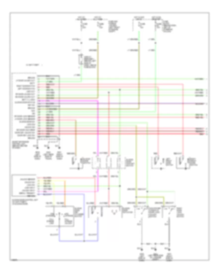
POWER SEATS
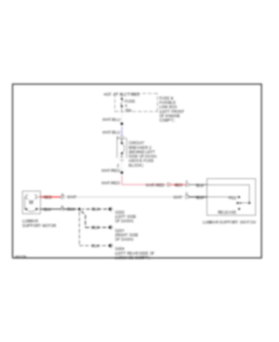
Lumbar Wiring Diagram for Nissan Quest XE 1998
List of elements for Lumbar Wiring Diagram for Nissan Quest XE 1998:
- Circuit breaker 2 (behind left side of dash, above fuse block)
- Fill
- Fuse & fusible link box (left front of engine compt)
- Fuse a 30a
- G201 (right side of dash)
- G202 (left side of dash)
- G404 (left rear side of luggage compt)
- Hot at all times
- Lumbar support motor
- Lumbar support switch
- Red
- Release
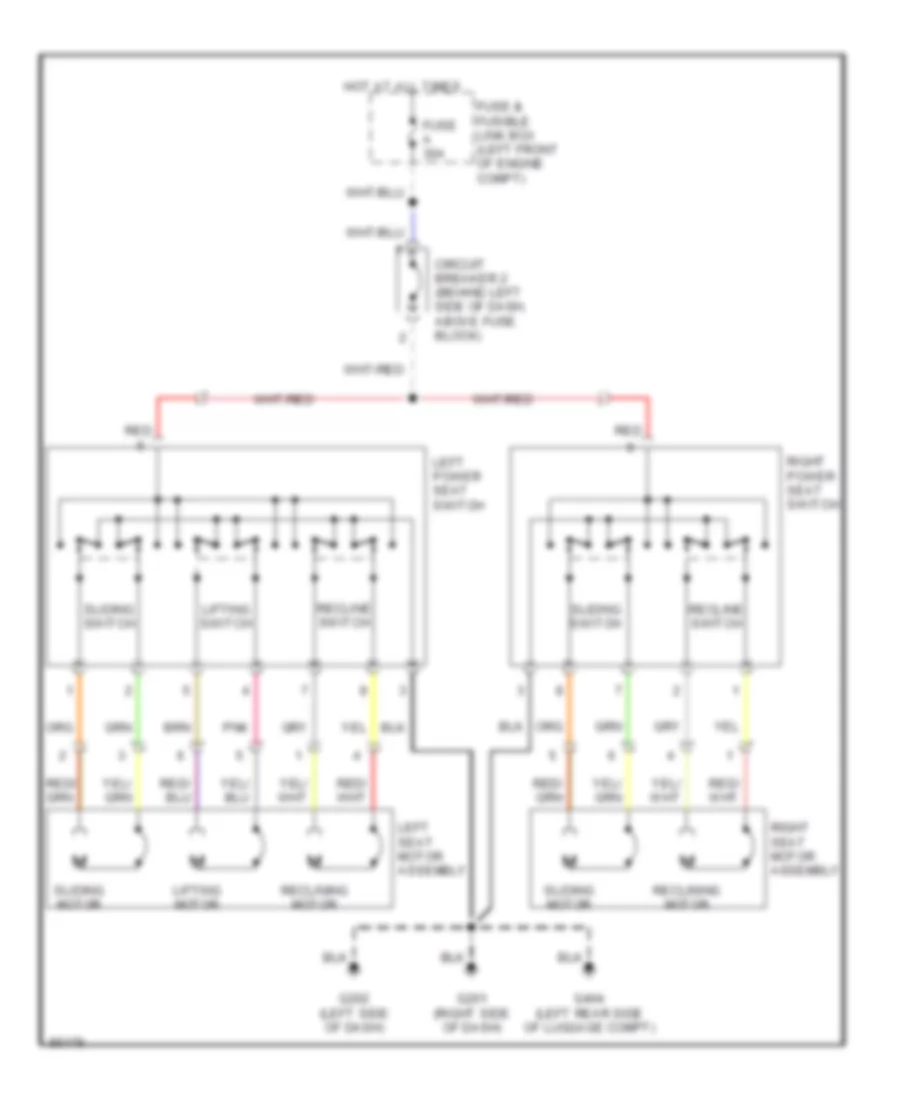
Power Seats Wiring Diagram for Nissan Quest XE 1998
List of elements for Power Seats Wiring Diagram for Nissan Quest XE 1998:
- Circuit breaker 2 (behind left side of dash, above fuse block)
- Fuse & fusible link box (left front of engine compt)
- Fuse a 30a
- G201 (right side of dash)
- G202 (left side of dash)
- G404 (left rear side of luggage compt)
- Hot at all times
- Left power seat switch
- Left seat motor assembly
- Lifting motor
- Lifting switch
- Pnk
- Recline switch
- Reclining motor
- Red
- Right power seat switch
- Right seat motor assembly
- Sliding motor
- Sliding switch
POWER TOP/SUNROOF
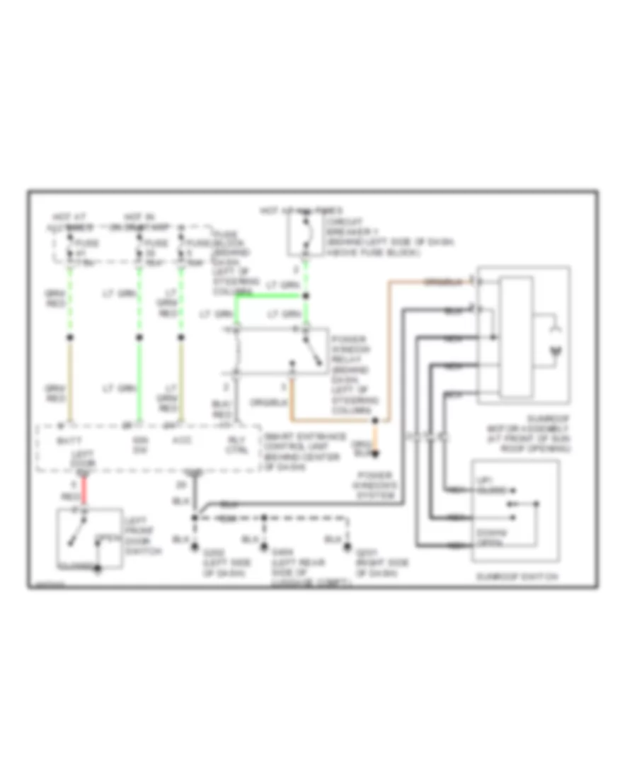
Power Top/Sunroof Wiring Diagrams for Nissan Quest XE 1998
List of elements for Power Top/Sunroof Wiring Diagrams for Nissan Quest XE 1998:
- Acc
- Batt
- Circuit breaker 1 (behind left side of dash, above fuse block)
- Closed
- Down/ open nca
- Fuse 10a
- Fuse 7.5a
- Fuse block (behind dash, left of steering column)
- G201 (right side of dash)
- G202 (left side of dash)
- G404 (left rear side of luggage compt)
- Gnd
- Hot at all times
- Hot in on or start
- Ign sw
- Left door sw
- Left front door switch
- Nca
- Open
- Power window relay (behind dash, left of steering column)
- Power windows system
- Red
- Rly ctrl
- Smart entrance control unit (behind center of dash)
- Sunroof motor assembly (at front of sun roof opening)
- Sunroof switch
- Up/ close
POWER WINDOWS
Power Window Wiring Diagram for Nissan Quest XE 1998
List of elements for Power Window Wiring Diagram for Nissan Quest XE 1998:
- Auto down module
- Circuit breaker-1 (behind left side of dash, above fuse block)
- Close
- Closed
- Control unit (behind center of dash)
- Down
- Front left
- Front right window switch
- Fuse 10a
- Fuse 7.5a
- Fuse box (behind dash, left of steering column)
- G201 (right side of dash)
- G202 (left side of dash)
- G404 (left rear side of luggage compt)
- Hot at all times
- Hot in on or start
- Interior lights system (instrument illumination)
- Left front door open
- Left front power window motor
- Left rear power vent window motor
- Main power window & door lock/ unlock switch
- Nca
- Open
- Pnk
- Power tops system
- Power window relay (behind left side of dash)
- Rear power vent window switch
- Red
- Right front power window motor
- Right front power window switch
- Right rear power vent window motor
- Smart entrance
- Switch
- Window lockout switch
- Window switch
RADIO
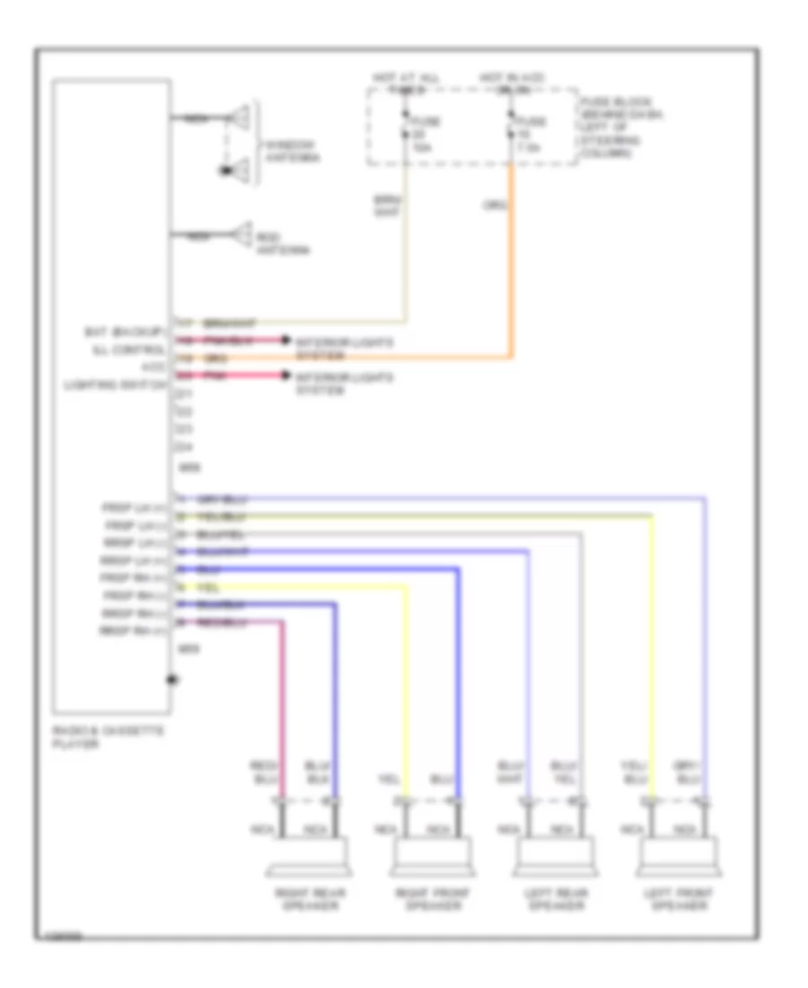
Base Radio for Nissan Quest XE 1998
List of elements for Base Radio for Nissan Quest XE 1998:
- Acc
- Bat (backup)
- Frsp lh (+)
- Frsp lh (-)
- Frsp rh (+)
- Frsp rh (-)
- Fuse 10a
- Fuse 7.5a
- Fuse block (behind dash, left of steering column)
- Hot at all times
- Hot in acc or on
- Ill control
- Interior lights system
- Left front speaker
- Left rear speaker
- Lighting switch
- M58
- M59
- Nca
- Pnk
- Radio & cassette player
- Right front speaker
- Right rear speaker
- Rod antenna
- Rrsp lh (+)
- Rrsp lh (-)
- Rrsp rh (+)
- Rrsp rh (-)
- Window antenna
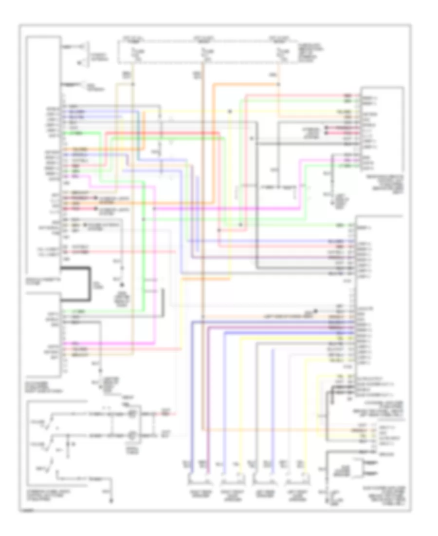
Premium Sound Radio Wiring Diagram for Nissan Quest XE 1998
List of elements for Premium Sound Radio Wiring Diagram for Nissan Quest XE 1998:
- (+)
- (-)
- (center rear of dash) g206
- (left side of dash) g202
- 1996-97
- 4-channel amplifier (if equipped) (behind trim panel, above left rear wheelwell)
- Acc
- Acp a
- Acp b
- Ant-signal
- Asyson
- Bat
- Cd changer (if equipped) (right side of dash)
- Din cord
- Fuse 10a
- Fuse 20a
- Fuse 7.5a
- Fuse block (behind dash, left of steering column)
- G206 (center rear of dash)
- G404 (left side of cargo area)
- Gnd
- Ground
- Hot at all times
- Hot in acc or on
- Ill (+)
- Ill (-)
- Input (+)
- Input (-)
- Interior lights system
- Left front door speaker
- Left rear speaker
- Lfsp (+)
- Lfsp (-)
- Lrsp (+)
- Lrsp (-)
- M121
- M122
- M60
- M61
- M62
- Mute input
- Mute output
- Nca
- Next
- Pae
- Pnk
- Power antenna system
- Radio & cassette player
- Rear radio remote control unit (if equipped) (behind driver's seat)
- Red
- Rfsp (+)
- Rfsp (-)
- Right front door speaker
- Right rear speaker
- Rod antenna
- Rrsp (+)
- Rrsp (-)
- Shield
- Spiral cable
- Steering wheel radio control switches (if equipped)
- Sub woofer amplifier (if equipped) (behind trim panel, above right rear wheelwell)
- Sub woofer out (+)
- Sub woofer out (-)
- Sub- woofer speaker
- Un-mute
- Vol (+)/next
- Vol (-)/next
- Volume (+)
- Volume (-)
- Window antenna
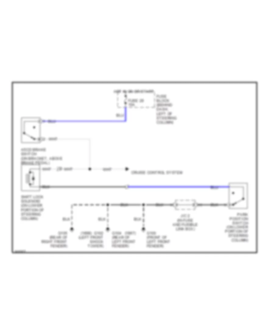
SHIFT INTERLOCKS
Shift Interlock Wiring Diagram for Nissan Quest XE 1998
List of elements for Shift Interlock Wiring Diagram for Nissan Quest XE 1998:
- (1997)
- (1998)
- Ascd brake switch (on bracket, above brake pedal)
- Cruise control system
- Fuse 29 10a
- Fuse block (behind dash, left of steering column)
- G100 (front of left front fender)
- G102 (left front shock tower)
- G104 (rear of left front fender)
- G105 (rear of right front fender)
- Hot in on or start
- J/c 2 (in fuse and fusible link box)
- Park position switch (on lower portion of steering column)
- Shift lock solenoid (on lower portion of steering column)
STARTING/CHARGING
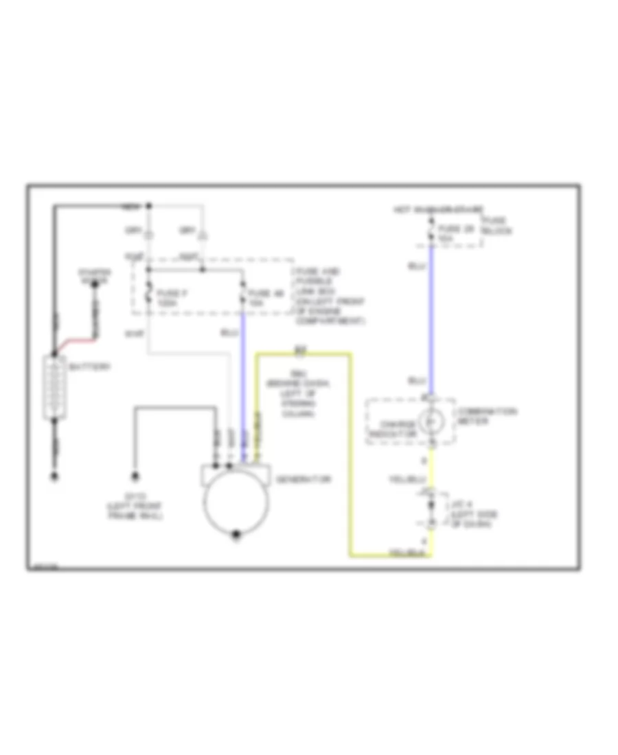
Charging Wiring Diagram for Nissan Quest XE 1998
List of elements for Charging Wiring Diagram for Nissan Quest XE 1998:
- Battery
- Charge indicator
- Combination meter
- Fuse 29 10a
- Fuse 48 10a
- Fuse and fusible link box (on left front of engine compartment)
- Fuse block
- Fuse f 120a
- G113 (left front frame rail)
- Generator
- Hot in on or start
- J/c 4 (left side of dash)
- Nca
- Smj (behind dash, left of steering column)
- Starter motor
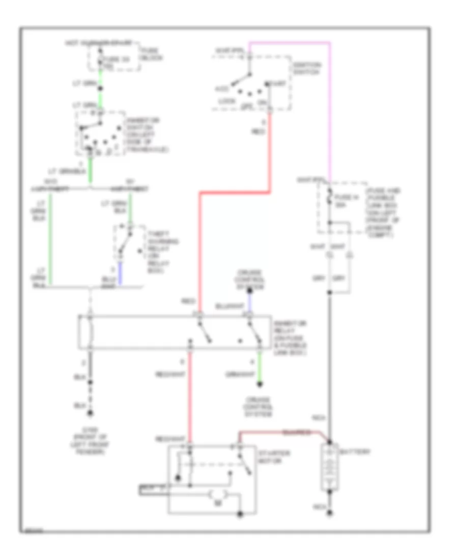
Starting Wiring Diagram for Nissan Quest XE 1998
List of elements for Starting Wiring Diagram for Nissan Quest XE 1998:
- Acc
- Battery
- Cruise control system
- Fuse 30 10a
- Fuse and fusible link box (on left front of engine compt)
- Fuse block
- Fuse h 30a
- G100 (front of left front fender)
- Hot in on or start
- Ignition switch
- Inhibitor relay (on fuse & fusible link box)
- Inhibitor switch (on left side of transaxle)
- Lock
- Nca
- Off
- Red
- Start
- Starter motor
- Theft warning relay (on relay box)
- W/ anti-theft
- W/o anti-theft
SUPPLEMENTAL RESTRAINTS
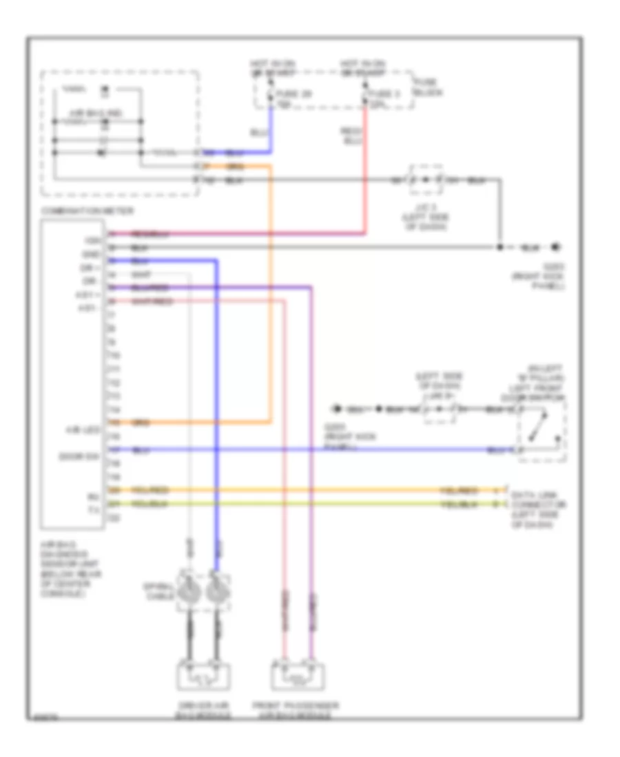
Supplemental Restraint Wiring Diagram for Nissan Quest XE 1998
List of elements for Supplemental Restraint Wiring Diagram for Nissan Quest XE 1998:
- (in left "b" pillar) left front door switch
- (left side of dash) j/c 3
- A/b led
- Air bag diagnosis sensor unit (below rear of center console)
- Air bag ind.
- As1 +
- As1 -
- Combination meter
- Data link connector (left side of dash)
- Door sw
- Dr +
- Dr -
- Driver air bag module
- Front passenger air bag module
- Fuse 29 10a
- Fuse 3 10a
- Fuse block
- G203 (right kick panel)
- Gnd
- Hot in on or start
- Ign
- J/c 3 (left side of dash)
- Nca
- Spiral cable
TRANSMISSION
A/T Wiring Diagram for Nissan Quest XE 1998
List of elements for A/T Wiring Diagram for Nissan Quest XE 1998:
- (on left side of transaxle) inhibitor switch
- 1 sw
- 2 sw
- A/t fluid temperature sensor
- All times
- Ascd
- Ascd control unit (behind center of dash)
- Atck
- Automatic transaxle red
- Avcc
- Closed throttle
- Clsd sw
- Combination meter
- D sw
- Data clk
- Data in
- Data link connector (for consult) (behind dash, next to fuse block)
- Data out
- Dropping resistor (lower left front corner of engine compt)
- Dt1
- Dt2
- Dt3
- Duty sol
- Eng rev
- Engine control module (ecm) (behind right side of dash)
- Engine coolant temperature sensor (on front of engine)
- Exterior lights system
- Fl temp
- Fuse 10a
- Fuse block (behind dash, left of steering column)
- G105 (rear of right front fender)
- G133 (on engine)
- G206 (center of dash)
- Gnd
- Gnd-a
- Hot at
- Hot in on or start
- Instrument cluster system
- J/c 2 (in fuse box)
- Line pressure solenoid valve
- Mem b/u
- N sw
- Nca
- Neut
- O/d off ind
- Obd2
- Od ind
- Od sw
- Over- run clutch sole- noid valve
- Overdrive control switch
- Ovr/c
- R sw
- Red
- Revolution sensor (on right side of transaxle)
- Sens gnd
- Sens pwr
- Shift sole- noid valve "a"
- Shift solenoid valve "b"
- Speedometer
- Ssa
- Ssb
- Tacho
- Th/sens
- Throttle position sensor (on throttle body)
- Throttle position switch (on throttle body)
- Torque con- verter clutch solenoid valve
- Transmission control module (tcm) (behind dash, right of steering column)
- Tvo
- Tvo1
- Vehicle speed sensor (on transaxle)
- Vign
- Vsp
- Vsp-1
- Vsp-2
- W/tmp
- Wo sw
- Wot
WARNING SYSTEMS
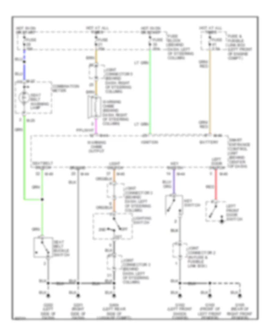
Warning System Wiring Diagrams for Nissan Quest XE 1998
List of elements for Warning System Wiring Diagrams for Nissan Quest XE 1998:
- 1st
- 2nd
- Battery
- Combination meter
- Fuse & fusible link box (left front of engine compt)
- Fuse 10a
- Fuse 15a
- Fuse 7.5a
- Fuse block (behind dash, left of steering column)
- G100 (front of left front fender)
- G102 (left front shock tower)
- G105 (rear of right front fender)
- G201 (right side of dash)
- G202 (left side of dash)
- G404 (left rear side of luggage compt)
- Ground
- Hot at all times
- Hot in on or start
- Ignition
- Joint connector 2 (in fuse & fusible link box)
- Joint connector 3 (behind dash, left of steering column)
- Joint connector 5 (behind dash, right of steering column)
- Key switch
- Left door switch
- Left front door switch
- Light switch
- Lighting switch
- M-26
- M-27
- M-44
- M-46
- Off
- Red
- Seat belt buckle switch
- Seat belt warning lamp
- Seatbelt switch
- Smart entrance control unit (behind center of dash)
- Warning chime (behind dash, right of steering column)
- Warning chime output
WIPER/WASHER
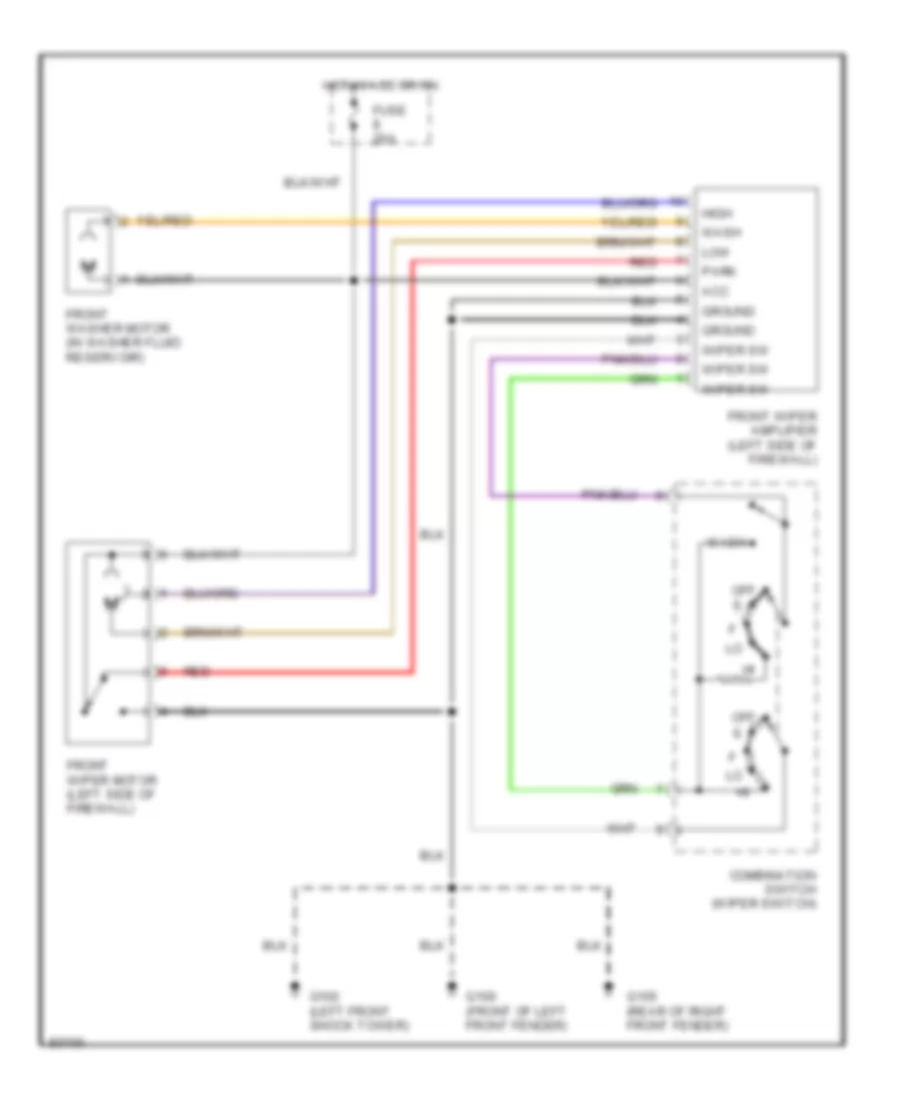
Front Wiper/Washer Wiring Diagram for Nissan Quest XE 1998
List of elements for Front Wiper/Washer Wiring Diagram for Nissan Quest XE 1998:
- Acc
- Combination switch (wiper switch)
- Front washer motor (in washer fluid reservoir)
- Front wiper amplifier (left side of firewall)
- Front wiper motor (left side of firewall)
- Fuse 20a
- G100 (front of left front fender)
- G102 (left front shock tower)
- G105 (rear of right front fender)
- Ground
- High
- Hot in acc or on
- Low
- Off
- Park
- Red
- Wash
- Wiper sw
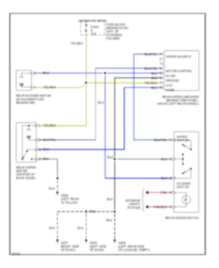
Rear Wiper/Washer Wiring Diagram, with Moveable Liftgate Glass for Nissan Quest XE 1998
List of elements for Rear Wiper/Washer Wiring Diagram, with Moveable Liftgate Glass for Nissan Quest XE 1998:
- Fuse 10a
- Fuse block (behind dash, left of steering column)
- G201 (right side of dash)
- G202 (left side of dash)
- G404 (left rear side of luggage compt)
- G999 (left rear 'd" pillar)
- Glass hatch latch switch (center of liftgate)
- Hot at all times
- Hot in acc or on
- Interior lights system
- Pnk
- Rear washer motor (in washer fluid reservoir)
- Rear wiper amplifier
- Rear wiper motor (center of back door)
- Rear wiper switch
- Washer switch
- Wiper switch
Rear Wiper/Washer Wiring Diagram, without Moveable Liftgate Glass for Nissan Quest XE 1998
List of elements for Rear Wiper/Washer Wiring Diagram, without Moveable Liftgate Glass for Nissan Quest XE 1998:
- Acc
- Fuse 10a
- Fuse block (behind dash, left of steering column)
- G201 (right side of dash)
- G202 (left side of dash)
- G404 (left rear side of luggage compt)
- G999 (left rear "d" pillar)
- Ground
- Hot in acc or on
- Interior lights system
- Motor control
- Park
- Pnk
- Rear washer motor (in washer fluid reservoir)
- Rear wiper amplifier (behind trim panel, above left rear wheel)
- Rear wiper motor (center of back door)
- Rear wiper switch
- Wash
- Washer switch
- Wiper on input
- Wiper switch

 Čeština
 Dansk
Dansk Deutsch
 Ελληνικά
 English
 Español
 Suomi
Suomi Français
 Français
 עברית
עברית Hrvatski
 Magyar
 Italiano
 日本語
日本語 한국어
한국어 Nederlands
 Polski
 Português
 Português
 Română
 Русский
 Slovenčina
 Slovenščina
 Svenska
 Türkçe
 中文 (中国)