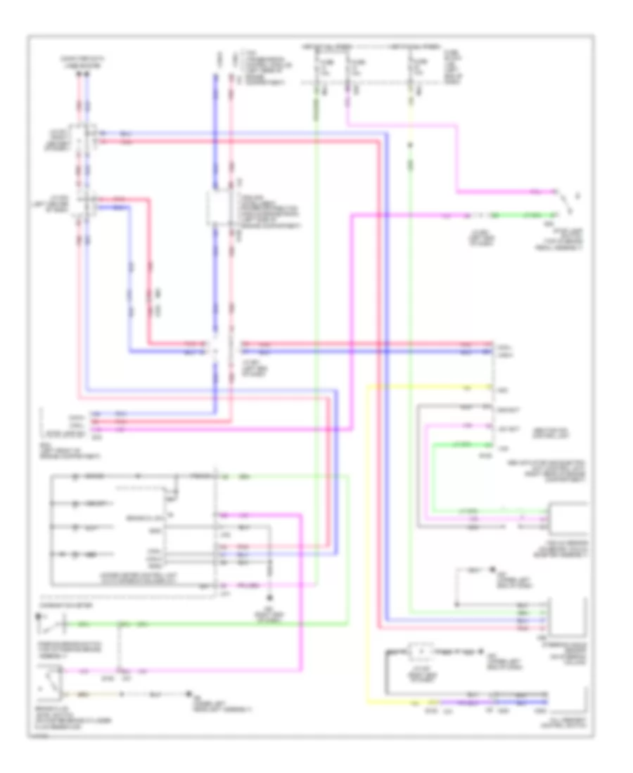
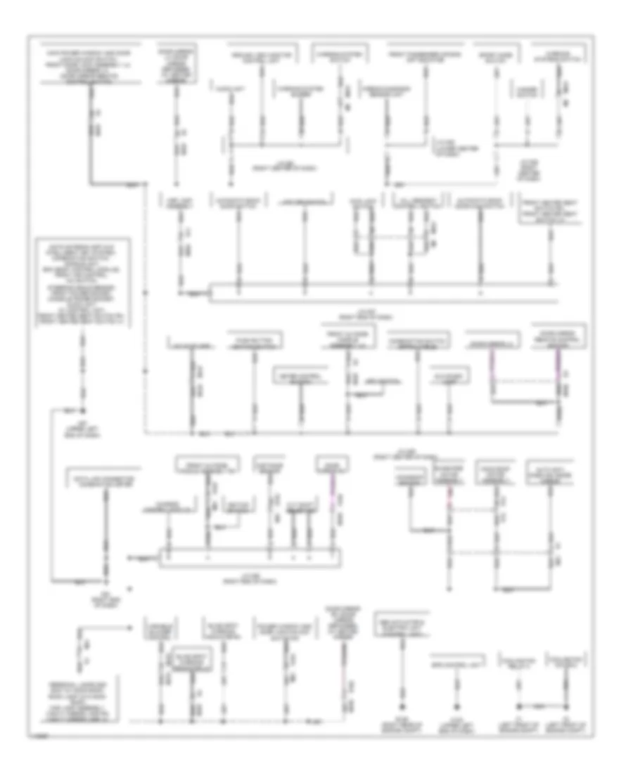
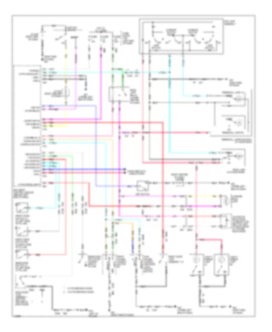
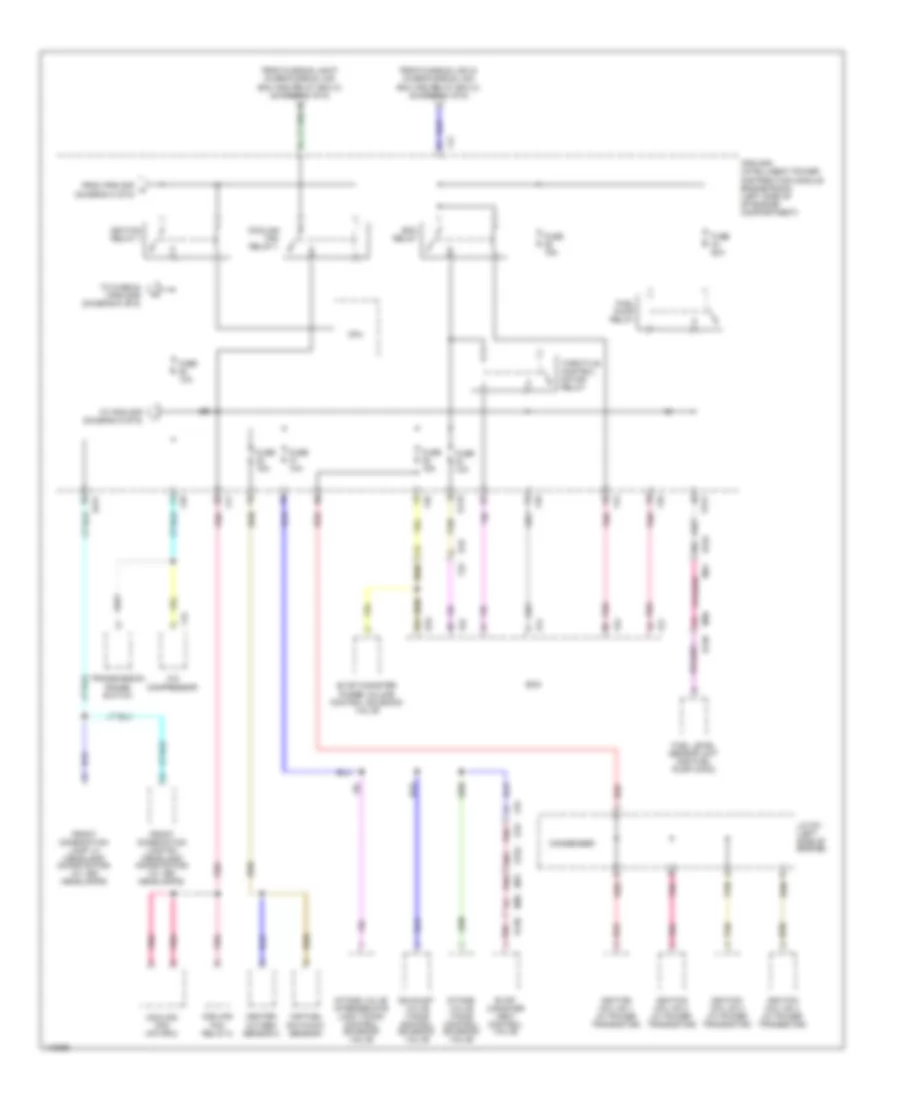
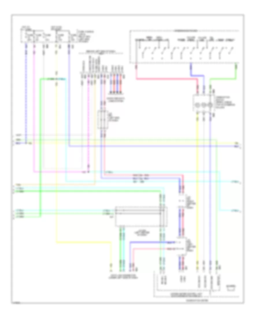
AIR CONDITIONING
Air Conditioning Wiring Diagram, Automatic A/C (1 of 2) for Nissan Rogue S 2014
 https://portal-diagnostov.com/license.html
Automotive Electricians Portal FZCO
Automotive Electricians Portal FZCO
https://portal-diagnostov.com/license.html
https://portal-diagnostov.com/license.html
Automotive Electricians Portal FZCO
Automotive Electricians Portal FZCO
List of elements for Air Conditioning Wiring Diagram, Automatic A/C (1 of 2) for Nissan Rogue S 2014:
- (bottom left side of hvac unit)
- (left center of dash)
- (left center of dash) j/c m03
- (left end of dash) j/c b01
- (left end of dash)
- (lower center of dash) j/c m18
- 16p
- 16r
- A/c auto amplifier
- A/c compressor (lower left front of engine)
- A/c relay
- A/c switch
- B14
- B16
- Bat
- Bcm (body control module) (behind left end of dash)
- Can-h
- Can-l
- Computer data lines system
- Cpu
- E119
- E120
- E121
- E15 (under left headlight assembly)
- E152
- Electrical control valve
- F35
- F42
- F53 (front of engine)
- F57 (front of engine)
- Front blower relay
- Front blower motor (upper center of hvac unit)
- Fuse 10a
- Fuse 15a
- Fuse 20a
- Fuse block (j/b)
- Gnd (pwr)
- Hot at all times
- Hot in on or start
- Ignition relay
- In-vehicle sensor (lower center of dash)
- Incar sens
- Ipdm e/r (intelligent power distribution module engine room) (left side of engine compt)
- J/c m01 (right center of dash)
- J/c m02
- Lin sw amp
- M123
- M123 m132
- M125
- M125 m127
- M127
- M127 m125
- M132
- M133
- M134
- M18
- M31
- M33
- M44
- M54
- M57 (upper left end of dash)
- M57 (upper left end of dash)
- M61 (right end of dash)
- M68
- M69
- Magnetic clutch
- O ign2 rl
- Pnk
- Red
- Sens gnd
- Sensor (top center of dash)
- Sun sens
- Sunload
- Variable blower control (left side of hvac unit)
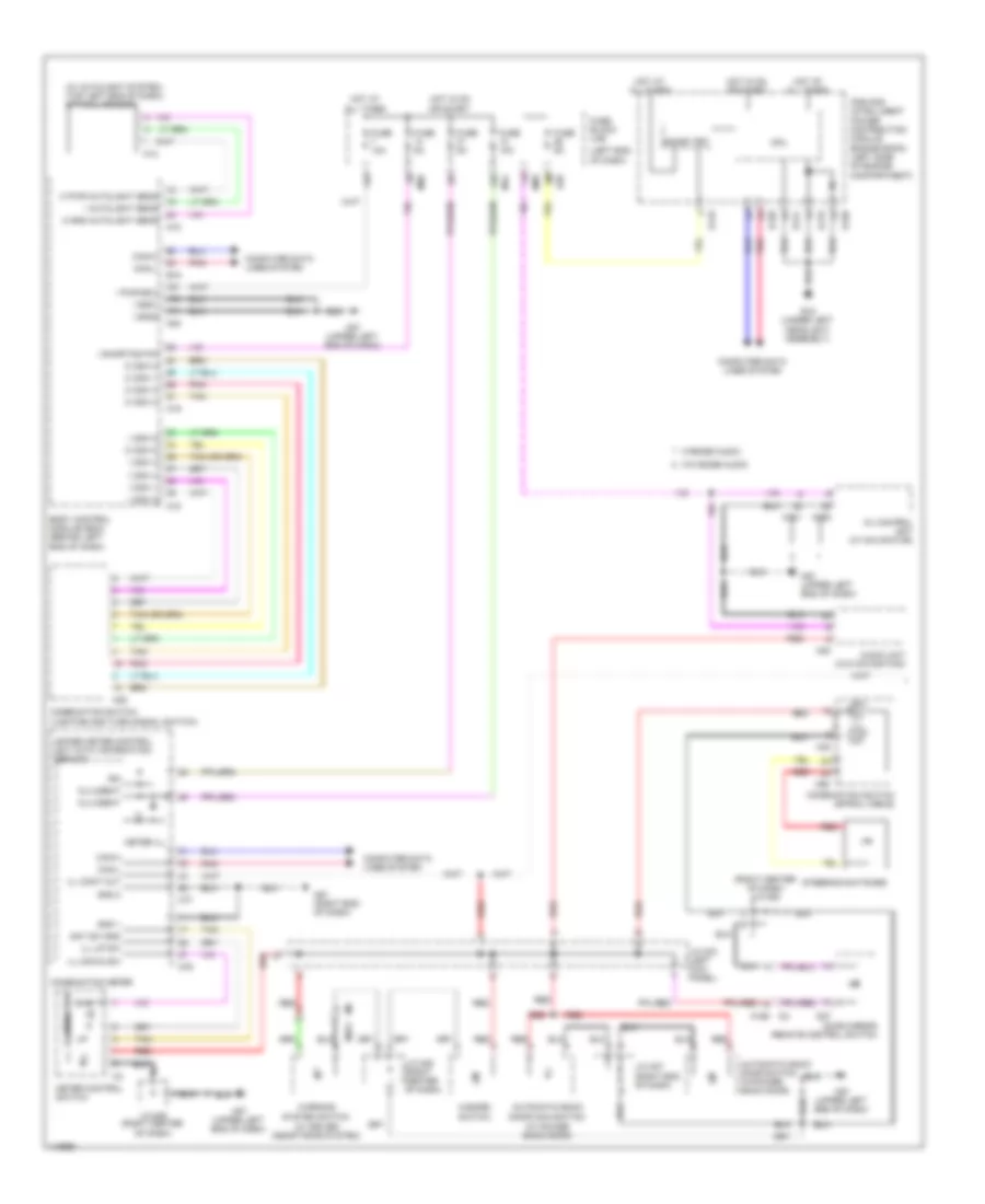
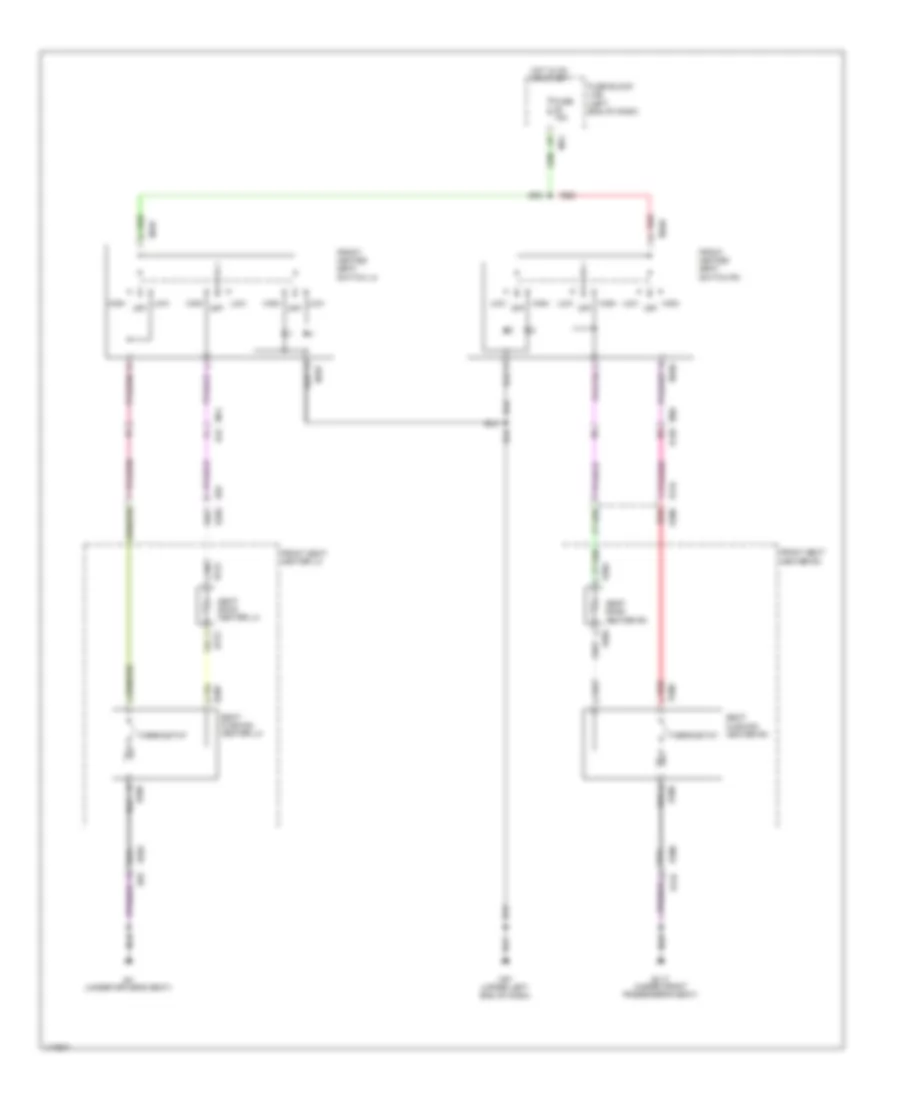
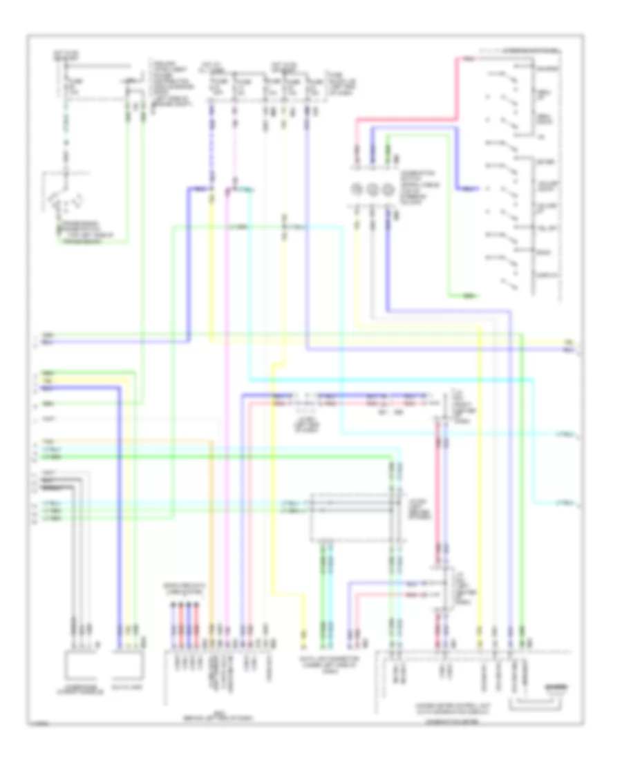
Air Conditioning Wiring Diagram, Automatic A/C (2 of 2) for Nissan Rogue S 2014
List of elements for Air Conditioning Wiring Diagram, Automatic A/C (2 of 2) for Nissan Rogue S 2014:
- (bottom left side of hvac unit)
- (left end
- (on front evaporator)
- 12v prot motor 12
- 12v prot motor 34
- A/c auto amplifier
- Amp
- Avcc1-pdpres
- Can-h
- Can-l
- E16
- Ecm (left front of
- Engine compt)
- F33 e19
- Fr fan f/b
- Fr fan out
- Gnda-pdpres
- Hvac blower housing)
- Intake 1
- Intake 2
- Intake 3
- Intake 4
- Intake door motor (bottom left of
- Intake sensor
- Intake sensor gnd
- J/c e01
- Left air mix door motor (lower left side of hvac unit)
- M55
- Mix as 3
- Mix as 4
- Mix as1
- Mix as2
- Mix dr 3
- Mix dr 4
- Mix dr1
- Mix dr2
- Mode 1
- Mode 2
- Mode 3
- Mode 4
- Mode door motor (left side of hvac unit)
- Of dash)
- Pdpres
- Pnk
- Red
- Refrigerant pressure sensor (right front of engine compt)
- Right air mix door motor (lower right side of hvac unit)
- Tan
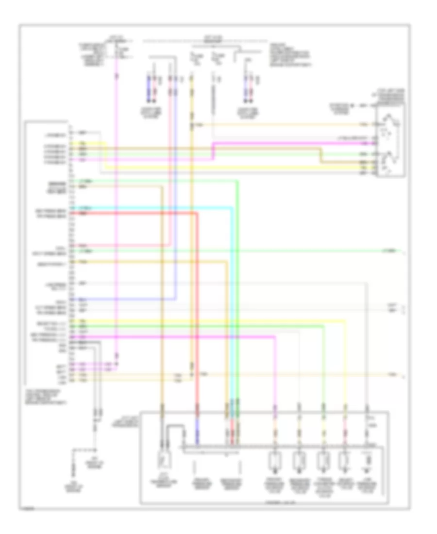
Air Conditioning Wiring Diagram, Manual A/C for Nissan Rogue S 2014
List of elements for Air Conditioning Wiring Diagram, Manual A/C for Nissan Rogue S 2014:
- (left center of dash)
- (left end of dash)
- (on front evaporator)
- (or red)
- (or tan) red
- (upper center of hvac unit) front blower motor
- 12v prot motor
- 16p
- 16r
- 61j
- 62j
- A/c compressor
- A/c relay
- Air mix door motor (lower side of hvac unit)
- Amp
- Avcc1-pdpres
- B16
- B41
- Bcm (body control module) (behind left end of dash)
- Can-h
- Can-l
- Computer data lines system
- Cpu
- E119
- E120
- E121
- E15 (under left headlight assembly)
- E152
- E16
- Ecm (left front of
- Electrical control valve
- Engine compartment)
- F33 e19
- F35
- F42
- F53 (front of engine)
- F57 (front of engine)
- Fr fan f/b
- Fr fan out
- Front blower relay
- Front air control
- Fuse 10a
- Fuse 15a
- Fuse 20a
- Fuse block (j/b)
- Gnd
- Gnda-pdpres
- Hot at all times
- Hot in on or start
- Hvac blower housing)
- Ign tempo
- Ignition relay
- Ignw
- Intake 1
- Intake 2
- Intake 3
- Intake 4
- Intake door motor (bottom left of
- Intake sens
- Intake sens gnd
- Intake sensor
- Ipdm e/r (intelligent power distribution module engine room) (left side of engine compartment)
- J/c b01 (left end of dash)
- J/c e01
- J/c m01 (right center of dash)
- J/c m02 (left center of dash)
- J/c m03
- M123
- M125
- M127
- M132
- M18
- M31
- M33
- M44
- M57 (upper left end of dash)
- M61 (right end of dash)
- M68
- M69
- Magnetic clutch
- Mix dr 1
- Mix dr 2
- Mix dr 3
- Mix dr 4
- Mode 1
- Mode 2
- Mode 3
- Mode 4
- Mode door motor (left side of hvac unit)
- Nca
- O ign2 rl
- Pnk
- Red
- Refrigerant pressure sens
- Refrigerant pressure sensor (right front of engine compt)
- Tan
- Variable blower control (left side of hvac unit)
ANTI-LOCK BRAKES
Anti-lock Brakes Wiring Diagram (1 of 2) for Nissan Rogue S 2014
List of elements for Anti-lock Brakes Wiring Diagram (1 of 2) for Nissan Rogue S 2014:
- (on respective hub assembly)
- 21j
- 46j
- 78a
- 79a
- 80a
- 81a
- Abs actuator and electric unit (control unit) (right rear of engine
- Abs/tcs/vdc control unit
- Actuator
- B40
- Compartment)
- E125
- E126 (right rear of engine compartment)
- E152
- E34
- Fl in
- Fl out
- Fr in
- Fr out
- Front wheel sensor lh
- Front wheel sensor rh
- Fuse 10a
- Fuse block (j/b) (left end of dash)
- Fuse/ fusible link & relay box 1 (left side of engine compartment)
- Fusible link h 30a
- Fusible link l 40a
- Gnd ecu
- Gnd mr
- Hot at all times
- Hot in acc or on
- Hsv 1
- Hsv 2
- Interior lights system
- J/c m27 (right end of dash)
- M31
- M57 (upper left end of dash)
- M68
- M79
- Motor
- Motor relay
- Pnk
- Rear wheel sensor lh
- Rear wheel sensor rh
- Red
- Relay unit
- Rl in
- Rl out
- Rr in
- Rr out
- Solenoid valve relay
- Tan
- Ub mr
- Ub vr
- Usv 1
- Usv 2
- Vdc off
- Vdc off switch
- Wau
- Wsp fl
- Wsp fr
- Wsp rl
- Wsp rr
- Wss fl
- Wss fr
- Wss rl
- Wss rr
Anti-lock Brakes Wiring Diagram (2 of 2) for Nissan Rogue S 2014
List of elements for Anti-lock Brakes Wiring Diagram (2 of 2) for Nissan Rogue S 2014:
- (left end of dash)
- 13p
- 27j
- 30j
- 47j
- 61j
- 62j
- Abs
- Abs actuator and electric unit (control unit) (right rear of engine compartment)
- Abs/tcs/vdc control unit
- Bat
- Brake
- Brake fluid level switch (on master brake cylinder
- Brake oil sw
- Can-h
- Can-l
- Combination meter
- Computer data
- E120
- E125
- E152
- E152 m31
- E16
- E28
- E38
- E9 (under left headlight assembly)
- Ecm (left front of engine compartment)
- End of dash)
- Engine compartment)
- F42
- F75
- Fluid reservoir)
- Fuse 10a
- Fuse block (j/b) (left
- Gnd ext
- Gnd1
- Gnd2
- Hdc
- Hill descent control switch
- Hot at all times
- Ipdm e/r (intelligent power distribution module engine room) (left side of
- J/c e01
- J/c e01 (left end of dash)
- J/c m01 (right center of dash)
- J/c m02 (left center of dash)
- J/c m27 (right end of dash)
- Lines system
- M254
- M31
- M44
- M56
- M57 (upper left end of dash)
- M61 (right end of dash)
- M76
- M77
- M9 m251
- Nca
- Parking brake switch (top of parking brake assembly)
- Pkb sw
- Pnk
- Slip
- Steering angle sensor (on steering column)
- Stop lamp sw
- Stop lamp switch (top of brake pedal assembly)
- Tcm (transmission control module) (left rear of engine compartment)
- U5v ext
- Unified meter control unit (with information display)
- Vac
- Vacuum sensor (on brake vacuum booster assembly)
- Vdc off
ANTI-THEFT
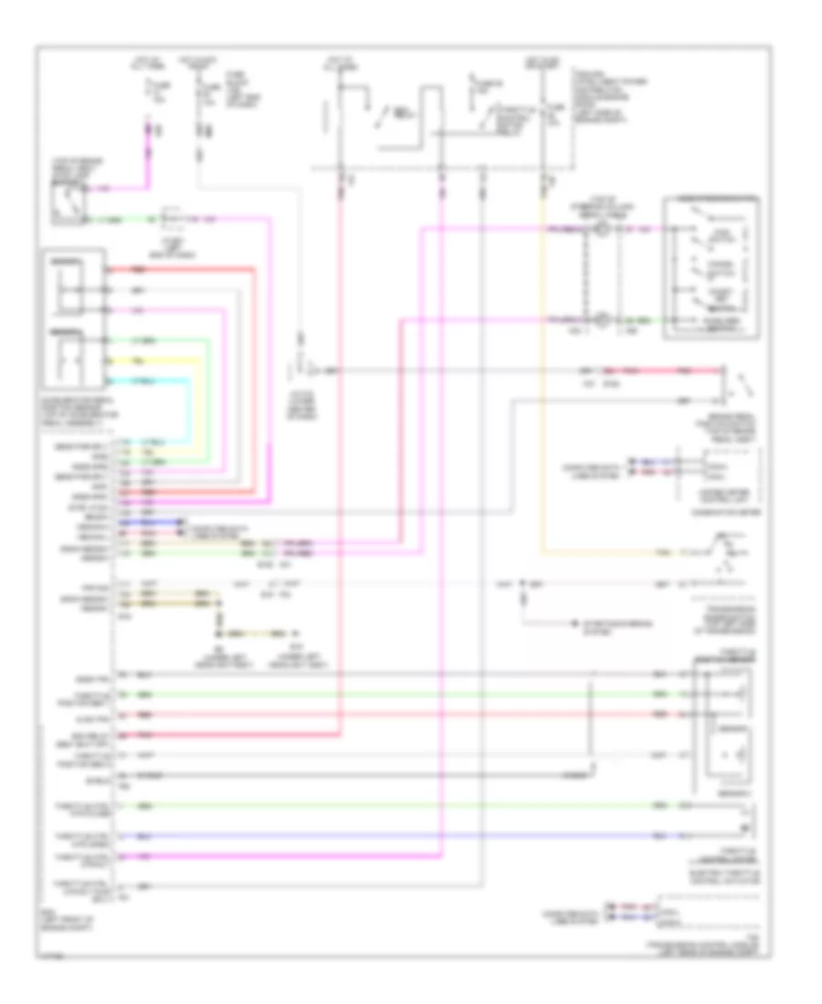
Engine Start Function Wiring Diagram, with Intelligent Key Unit for Nissan Rogue S 2014
List of elements for Engine Start Function Wiring Diagram, with Intelligent Key Unit for Nissan Rogue S 2014:
- (in fuse/fusible link and relay box 2)
- (left end of dash) fuse block(j/b)
- (left side of engine compartment) ipdm e/r (intelligent power distribution module engine room)
- 13p
- 14r
- 37j
- Antenna a
- B140
- B16
- B41 m69
- B49
- Bcm (body control module) (behind left end of dash)
- Buzzer
- Can-h
- Can-l
- Combination meter
- Computer data lines system
- Computer data lines system
- Cpu
- Cvt shift selector (base of shift lever assembly)
- E119
- E120
- E121
- E15 (under left headlight assembly)
- E152
- E16
- E19
- E28
- E29
- Ecm (left front of engine compartment)
- Escl sw
- F32
- F33
- F35
- F41
- F42
- F78
- Front door switch lh (left "b" pillar)
- Front door switch rh (right "b" pillar)
- Front outside handle assembly lh (front outside door handle lh)
- Front outside handle assembly rh (front outside door handle rh)
- Fuse 10a
- Fuse 5a
- Fuse/fusible link and relay box 1 (left side of engine compartment)
- Fusible link m 30a
- Gnd1
- Gnd2
- Hot at all times
- Hot in on or start
- I as door2 sw
- I at locked in park sw
- I brake sw2
- I dr door2 sw
- I gnd1
- I gnd2
- I pwr ecu
- I rl door sw
- I rr door sw
- Ignition relay-2
- Inside key antenna (console) (under rear of center console)
- Inside key antenna (instrument center) (under front of center console)
- J/c e01 (left end of dash)
- J/c m29 (right center of dash)
- J/c m30 (right center of dash)
- M107
- M168 d3
- M17
- M18
- M20
- M31
- M44
- M57 (upper left end of dash)
- M61 (right end of dash)
- M68
- M69 b41
- M76
- M77
- M91 d101
- O ign1 rl
- O pwr atdvc
- O security led
- O start sw backlight led i start wo
- O stcut rl
- Outside key antenna (rear bumper) (behind center of rear bumper)
- Pnk
- Push button ignition switch
- Rear door switch lh (left "c" pillar)
- Rear door switch rh (right "c" pillar)
- Red
- Security
- Ses ext as antenna a
- Ses ext as antenna b
- Ses ext dr antenna a
- Ses ext dr antenna b m19
- Ses ext rear antenna a
- Ses ext rear antenna b
- Ses int front antenna a
- Ses int front antenna b
- Ses int middle antenna b ses int middle
- Starter cut relay
- Starter relay
- Starting/charging system
- Stop lamp switch (top of brake pedal assembly)
- Tan
- Transmission range switch (top left side of transmission)
- Unified meter control unit (with information display)
Forced Entry Wiring Diagram for Nissan Rogue S 2014
List of elements for Forced Entry Wiring Diagram for Nissan Rogue S 2014:
- lines system
- (in fuse/fusible link & relay box 1) horn relay
- (left "b" pillar)
- (left end of dash)
- (upper left end of dash)
- 13p
- 14r
- Anti-theft horn relay (in relay box)
- B140
- B141
- B142
- B16
- B19 (left "d" pillar)
- B46
- B49
- B54 d505
- B70
- B71
- Back door lock assembly (bottom center of back door)
- Bcm (body control module) (behind left end of dash)
- Between full stroke and n
- Can-h
- Can-l
- Combination meter
- Computer data
- Cpu
- D101
- D501
- D508
- D512
- Door locks system
- E119
- E120
- E121
- E15 (under the left headlight assembly)
- E201
- E217
- E40
- E46
- E47
- E48
- E49
- Front door lock assembly lh
- Front door switch lh
- Front door switch rh (right "b" pillar)
- Full stroke
- Fuse 10a
- Fuse 15a
- Fuse 20a
- Fuse block (j/b)
- Fuse/fusible link & relay box 1 (left side of engine compartment)
- Gnd
- Headlight system
- Hood switch (center front of engine compartment)
- Horn (center front of engine compartment)
- Horn(low) (center front of engine compartment)
- Hot at all times
- I as door2 sw
- I doorlock sw
- I doorunlock sw
- I dr door2 sw
- I gnd1
- I gnd2
- I pwr doorlock1
- I pwr doorlock2
- I pwr ecu
- I rl door sw
- I rr door sw
- I ses as handle button sw
- I ses dr handle button
- I tgatesw
- I-key cylinder lock sw
- I-key cylinder unlock sw
- Ipdm e/r (intelligent power distribution module engine room) (left side of engine compartment)
- Lines system
- Lock
- M167
- M168
- M18
- M19
- M20
- M33
- M44
- M57
- M57 (upper left end of dash)
- M61 (right end of dash)
- M68
- M76
- M77
- M91
- Main power window and door lock/unlock switch
- O security led
- Pnk
- Power window and door lock/unlock switch rh
- Rear door switch lh (left "c" pillar)
- Rear door switch rh (right "c" pillar)
- Red
- Security
- Ses ext as antenna a
- Ses ext as antenna b
- Ses ext dr antenna a
- Ses ext dr antenna b
- Ses ext rear antenna a
- Ses ext rear antenna b
- Ses int front antenna a
- Ses int front antenna b
- Ses int middle antenna a
- Ses int middle antenna b
- Smart fet
- Switch
- Tan
- Unlock
- Unlock lock switch
- W/ power back door
- W/o power back door
Immobilizer Wiring Diagram, with Intelligent Key Unit for Nissan Rogue S 2014
List of elements for Immobilizer Wiring Diagram, with Intelligent Key Unit for Nissan Rogue S 2014:
- lines system
- (in fuse/fusible link and relay box 2)
- (left end of dash) fuse block(j/b)
- (left front of engine compartment) ecm
- (left side of engine compartment) ipdm e/r (intelligent power distribution module engine room)
- (right center of dash)
- (right center of dash) j/c m30
- (under left headlight assembly)
- 13p
- 14r
- 37j
- B16
- Bcm (body control module) (behind left end of dash)
- Buzzer
- Can-h
- Can-l
- Combination meter
- Computer data
- Computer data lines system
- Cpu
- Cvt shift selector (base of shift lever assembly)
- Dongle uart
- Dongle unit (top left center of dash) (for canada)
- E119
- E120
- E121
- E15
- E152
- E16
- E19
- E28
- E29
- F32
- F33
- F35
- F41
- F42
- F78
- Fuse 10a
- Fuse 5a
- Fuse/fusible link and relay box 1 (left side of engine compartment)
- Fusible link m 30a
- Gnd1
- Gnd2
- Hot at all times
- Hot in on or start
- I at locked in park sw m19
- I brake sw2
- I gnd1
- I gnd2
- I pwr ecu
- I start wo escl sw
- Ignition relay-2
- J/c e01 (left end of dash)
- J/c m29
- M107
- M17
- M18
- M20
- M25
- M31
- M44
- M57 (upper left end of dash)
- M61 (right end of dash)
- M68
- M76
- M77
- Nats antenna amplifier (left center of dash)
- O ign1 rl
- O immobilizer kazashi a
- O immobilizer kazashi b
- O pwr atdvc
- O security led
- O start sw backlight led
- O stcut rl
- Pnk
- Push button ignition switch
- Security
- Starter cut relay
- Starter relay
- Starting/ charging system
- Stop lamp switch (top of brake pedal assembly)
- Tan
- Transmission range switch (top left side of transmission)
- Unified meter control unit (with information display)
Immobilizer Wiring Diagram, without Intelligent Key Unit for Nissan Rogue S 2014
List of elements for Immobilizer Wiring Diagram, without Intelligent Key Unit for Nissan Rogue S 2014:
- lines system
- (in fuse/fusible link and relay box 2)
- (left end of dash) fuse block(j/b)
- (left front of engine compartment) ecm
- (left side of engine compartment) ipdm e/r (intelligent power distribution module engine room)
- (right center of dash) j/c m30
- (right end of dash)
- (under left headlight assembly)
- 12r
- 13p
- 14r
- 37j
- B16
- Bcm (body control module) (behind left end of dash)
- Buzzer
- Can-h
- Can-l
- Combination meter
- Computer data
- Computer data lines system
- Cpu
- Cvt shift selector (base of shift lever assembly)
- Dongle uart
- Dongle unit (top left center of dash) (for canada)
- E119
- E120
- E121
- E15
- E152
- E16
- E19
- E28
- E29
- F32
- F33
- F35
- F41
- F42
- F78
- Fuse 10a
- Fuse 5a
- Fuse/fusible link and relay box 1 (left side of engine compartment)
- Fusible link m 30a
- Gnd1
- Gnd2
- Hot at all times
- Hot in on or start
- I at locked in park sw
- I brake sw2
- I gnd1
- I gnd2
- I ign sw
- I key sw
- I pwr ecu
- I starter sw
- Ignition relay-2
- Ignition switch
- J/c e01 (left end of dash)
- J/c m26
- J/c m29 (right center of dash)
- Key switch
- M107
- M18
- M20
- M31
- M32
- M44
- M57 (upper left end of dash)
- M61 (right end of dash)
- M68
- M76
- M77
- Nats antenna amplifier (left center of dash)
- O clk immobilizer m19
- O data immobilizer
- O ign1 rl
- O pwr atdvc
- O security led
- O stcut rl
- Off
- Pnk
- Security
- Start
- Starter cut relay
- Starter relay
- Starting/ charging system
- Stop lamp switch (top of brake pedal assembly)
- Tan
- Transmission range switch (top left side of transmission)
- Unified meter control unit (with information display)
BODY CONTROL MODULES
Body Control Modules Wiring Diagram, with Intelligent Key (1 of 2) for Nissan Rogue S 2014
List of elements for Body Control Modules Wiring Diagram, with Intelligent Key (1 of 2) for Nissan Rogue S 2014:
- (for canada)
- (with intelligent key)
- 14r
- B16
- Bcm (body control module) (behind left end of dash)
- Can-h
- Can-l
- Computer data lines system
- Defogger system
- Dongle uart
- Dongle unit
- Door locks system
- E28
- Exterior & interior lights system
- Exterior lights &
- Exterior lights system
- Fuse 10a
- Fuse 15a
- Fuse 20a
- Fuse block (j/b) (left end of dash)
- Headlights
- Hot at all times
- I as door2 sw
- I autolight sensor
- I csw 1
- I csw 2
- I csw 3
- I csw 4
- I csw 5
- I doorlock sw
- I doorunlock sw
- I dr door2 sw
- I gnd 1
- I gnd 2
- I hazard sw d
- I pwr doorlock 1
- I pwr doorlock 2
- I pwr ecu
- I pwr flashers
- I pwr stop lamp
- I pwr wiper
- I rl door sw
- I rr autostop sw
- I rr door sw
- I ses backdoor button sw
- I tgate opener sw
- I tgate sw
- Instrument cluster system
- Interior lights system
- M18
- M20
- M33
- M57
- M68
- O as lock or unlock d
- O bat temp1 rl
- O csw 5
- O defroster rl d
- O di fr left d
- O di fr right d
- O dr or fr lock d
- O fr or dr unlock d
- O gnd autolight sensor
- O ign1 rl
- O ign2 rl
- O pwm roomlamp 1
- O pwr atdvc
- O pwr autolight sensor
- O security led
- O spare 4 rl n
- O stop lamp3
- O wl authorization rl
- Pnk
- Power distribution system
- Power windows system
- Red
- Ses ext rear antenna a
- Ses ext rear antenna b
- Ses int middle antenna a
- Ses int middle antenna b
- Tan
- Transmissions system
- Trunk, tailgate, fuel doors system
- Wiper/washer system
Body Control Modules Wiring Diagram, with Intelligent Key (2 of 2) for Nissan Rogue S 2014
List of elements for Body Control Modules Wiring Diagram, with Intelligent Key (2 of 2) for Nissan Rogue S 2014:
- (with intelligent key)
- Anti-lock brakes system
- Anti-theft system
- B23
- Bcm (body control module) (behind left end of dash)
- Door locks system
- E29
- Exterior lights &
- Exterior lights system
- Fuse 5a
- Fuse block (j/b) (behind left end of dash)
- Headlights
- Hot at all times
- I at locked in park sw
- I brake sw 1
- I brake sw 2
- I dr knob sw
- I key cylinder lock sw
- I key cylinder unlock sw
- I ses dr handle button sw
- I ses fr handle button sw
- I shorting pin
- I start sw
- Interior lights system
- M19
- M68
- Navigation & sound systems
- Navigation system
- O auto acc2
- O buzzer
- O csw 1
- O csw 2
- O csw 3
- O csw 4
- O di fr left e
- O di fr right e
- O di rr left b
- O di rr right b
- O immobilizer kazashi a
- O mr output
- O pwm roomlamp 5
- O rr lock b
- O rr unlock b
- O rr wiper
- O start sw backlight led
- O stcut rl
- O stop lamp 2 nissan eur
- O stop lamp1
- O tgate opener
- Pnk
- Red
- Ses ext as antenna a
- Ses ext as antenna b
- Ses ext dr antenna a
- Ses ext dr antenna b
- Ses int front antenna a
- Ses int front antenna b
- Starting system
- Tan
- Transmissions system
- Trunk, tailgate, fuel doors system
- Warning system
- Wiper/washer system
Body Control Modules Wiring Diagram, without Intelligent Key (1 of 2) for Nissan Rogue S 2014
List of elements for Body Control Modules Wiring Diagram, without Intelligent Key (1 of 2) for Nissan Rogue S 2014:
- (for canada)
- 14r
- B16
- Bcm (body control module) (behind left end of dash)
- Can-h
- Can-l
- Computer data lines system
- Defogger system
- Dongle uart
- Dongle unit
- Door locks system
- E28
- Exterior & interior lights system
- Exterior lights &
- Exterior lights system
- Fuse 10a
- Fuse 15a
- Fuse 20a
- Fuse block (j/b) (left end of dash)
- Headlights
- Hot at all times
- I as door2 sw
- I autolight sensor
- I csw 1
- I csw 2
- I csw 3
- I csw 4
- I csw 5
- I doorlock sw
- I doorunlock sw
- I dr door2 sw
- I gnd 1
- I gnd 2
- I hazard sw d
- I pwr doorlock 1
- I pwr doorlock 2
- I pwr ecu
- I pwr flashers
- I pwr stop lamp
- I pwr wiper
- I rl door sw
- I rr autostop sw
- I rr door sw
- I tgate opener sw
- I tgate sw
- Instrument cluster system
- Interior lights system
- M18
- M20
- M33
- M57 (upper left end of dash)
- M68
- O as lock or unlock d
- O bat temp1 rl
- O csw 5
- O defroster rl d
- O di fr left d
- O di fr right d
- O dr or fr lock d
- O fr or dr unlock d
- O gnd autolight sensor
- O ign1 rl
- O ign2 rl
- O pwm roomlamp 1
- O pwr atdvc
- O pwr autolight sensor
- O security led
- O spare 4 rl n
- O stop lamp3
- O wl authorization rl
- Pnk
- Power distribution system
- Power windows system
- Red
- Tan
- Transmissions system
- Trunk, tailgate, fuel doors system
- Wiper/washer system
Body Control Modules Wiring Diagram, without Intelligent Key (2 of 2) for Nissan Rogue S 2014
List of elements for Body Control Modules Wiring Diagram, without Intelligent Key (2 of 2) for Nissan Rogue S 2014:
- Anti-lock brakes system
- Anti-theft system
- B23
- Bcm (body control module) (behind left end of dash)
- Clk immobilizer
- Door locks system
- E29
- Exterior lights &
- Exterior lights system
- Fuse 5a
- Fuse block (j/b) (behind left end of dash)
- Headlights
- Hot at all times
- I at locked in park sw
- I brake sw 1
- I brake sw 2
- I dr knob sw
- I ign sw
- I key cylinder lock sw
- I key cylinder unlock sw
- I key sw
- I shorting pin
- I starter sw
- Interior lights system
- M19
- M68
- Navigation & sound systems
- Navigation system
- O auto acc2
- O csw 1
- O csw 2
- O csw 3
- O csw 4
- O data immobilizer
- O di fr left e
- O di fr right e
- O di rr left b
- O di rr right b
- O mr output
- O pwm roomlamp 5
- O rr lock b
- O rr unlock b
- O rr wiper
- O stcut rl
- O stop lamp 2 nissan eur
- O stop lamp1
- O tgate opener
- Pnk
- Power distribution system
- Red
- Starting system
- Tan
- Transmission system
- Trunk, tailgate, fuel doors system
- Wiper/washer system
COMPUTER DATA LINES
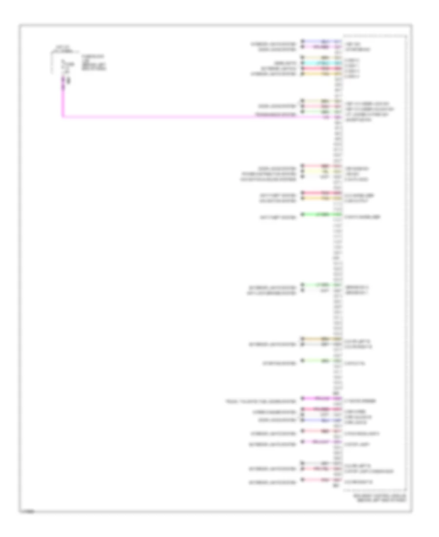
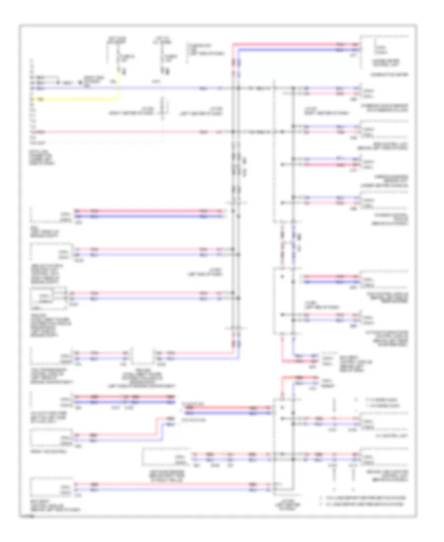
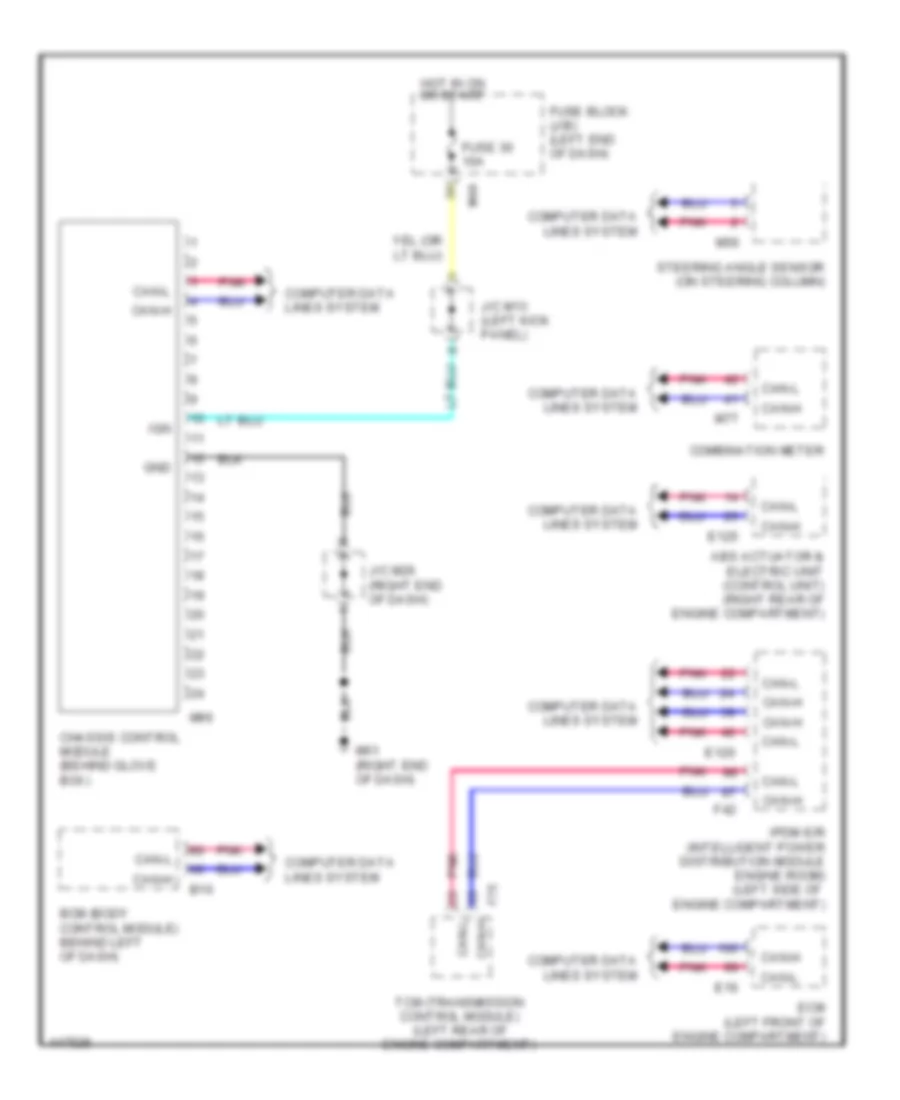
Computer Data Lines Wiring Diagram for Nissan Rogue S 2014
List of elements for Computer Data Lines Wiring Diagram for Nissan Rogue S 2014:
- can-l
- (behind glove box)
- (left center of dash)
- (left end of dash)
- (right end of dash) m61
- (under center console)
- 15r
- 33j
- 34j
- 61j
- 62j
- A/c auto amplifier (bottom left side of hvac unit)
- Abs actuator & electric unit (control unit) (right rear of engine compt)
- Airbag diagnosis sensor unit
- Around view monitor control unit (behind glove box)
- Automatic back door control module (behind left rear quarterpanel)
- Av control unit
- Awd control module (behind left end of rear bumper)
- B16
- B41
- B55
- B75
- Bcm (body
- Bcm (body control module) (behind left end of dash)
- Can-h
- Can-l
- Chassis control module
- Combination meter
- Control module) (behind left end of dash)
- Cpu
- Data link connector (under left side of dash)
- Distance sensor (behind right side
- E120
- E125
- E152
- E16
- E21
- Ecm (left front of engine compt)
- Eps control unit (behind left side of dash)
- F42
- F75
- Front air control
- Fuse 30 10a
- Fuse 6 10a
- Fuse block (j/b) (left end of dash)
- Hot at all times
- Hot in on or start
- Ipdm e/r (intelligent power distribution module engine room) (left side of engine compartment)
- Ipdm e/r (intelligent power distribution module engine room) (left side of engine compt)
- J/c b01
- J/c e01 (left end of dash)
- J/c m01 (right center of dash)
- J/c m02
- J/c m03 (left center of dash)
- J/c m23 (right center of dash)
- M10
- M101
- M103
- M108
- M113
- M125
- M127
- M18
- M31
- M44
- M49
- M50
- M54
- M56
- M68
- M69
- M77
- M96
- Of front grille)
- Pnk
- Red
- Steering angle sensor (on steering column)
- Tcm (transmission control module) (left rear of engine compartment)
- Unified meter control unit
- W/ auto a/c
- W/ bose audio
- W/ lane departure prevention system
- W/o auto a/c
- W/o bose audio
- W/o lane departure prevention system
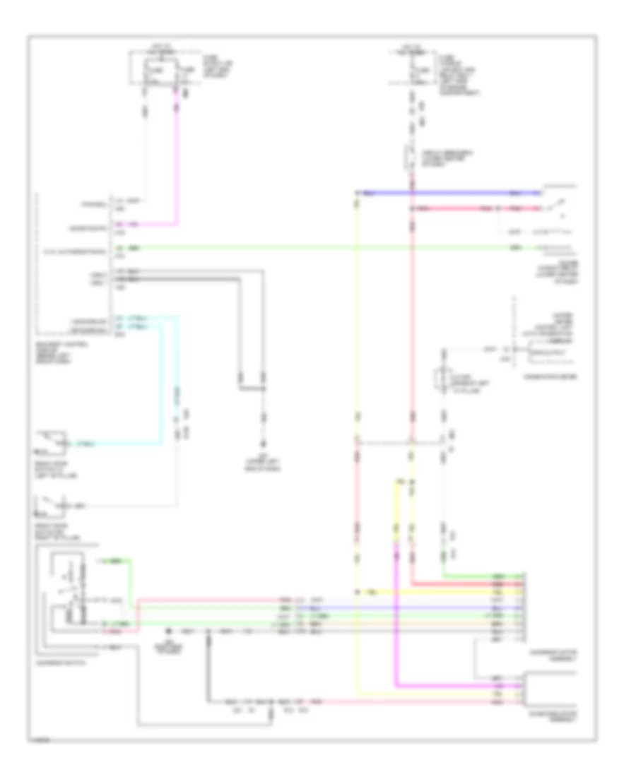
COOLING FAN
Cooling Fan Wiring Diagram for Nissan Rogue S 2014
List of elements for Cooling Fan Wiring Diagram for Nissan Rogue S 2014:
- (on ipdm e/r (intelligent power distribution module engine room))
- Can-h
- Can-l
- Computer data lines system
- Cooling fan motor 1 (right front of engine compartment)
- Cooling fan motor 2 (left front of engine compartment)
- Cooling fan relay 1
- Cooling fan relay 2
- Cooling fan relay 3
- Cpu
- E119
- E120
- E121
- E15 (under left headlight assembly)
- E16
- Ecm (left front of engine compartment)
- Engine coolant temperature sensor (rear of engine)
- F1 (left front of engine compartment)
- F2 (left front of engine compartment)
- F41
- F42
- F51
- Fuse 10a
- Fuse o 40a
- Fuse p 40a
- Fuse, fusible link and relay box 2 (under left headlight assembly)
- Hot at all times
- Ignition relay 1
- Ipdm e/r (intelligent power distribution module engine room) (left side of engine compt)
- J/c e01 (left end of dash)
- Pnk
- Sens gnd eng coolant temp sens
- Tan
CRUISE CONTROL
Cruise Control Wiring Diagram for Nissan Rogue S 2014
List of elements for Cruise Control Wiring Diagram for Nissan Rogue S 2014:
- (top of brake pedal assy) stop lamp switch
- (top of steering column) spiral cable
- (under left headlight assy)
- 16r
- 38j
- 41j
- 50j
- Accel/res switch
- Accelerator pedal position sensor (top of accelerator pedal assembly)
- Acsd steering switch
- Aps1
- Aps2
- Ascdsw
- Avcc-tps
- Bncsw
- Brake pedal position switch (top of brake pedal assy)
- Can-h
- Can-l
- Cancel
- Coast/ set
- Combination meter
- Computer data lines system
- E15
- E152
- E16
- E28
- Ecm (left front of engine compt)
- Ecm relay
- Ecm relay (self shut off)
- Electric throttle control actuator
- F33 e19
- F35
- F42
- F51
- F52
- Fuse 10a
- Fuse 36 15a
- Fuse block (j/b) (left end of dash)
- Gnda-aps1
- Gnda-aps2
- Gnda-ascdsw
- Gnda-tps
- Hot at all times
- Hot in acc or on
- Hot in on or start
- Ipdm e/r (intelligent power distribution module engine room) (left side of engine compt)
- J/c e01 (left end of dash)
- J/c m18 (lower center of dash)
- M30
- M31
- M31 e152
- M68
- M90
- Main switch
- Pnk
- Pnp sig
- Red
- Sens pwr sply
- Sensor 1
- Sensor 2
- Shield
- Starting/charging system
- Stop lp sw
- Switch
- Tan
- Tcm (transmission control module) (left rear of engine compt)
- Throttle control motor
- Throttle control motor relay
- Throttle position sensor
- Transmission range switch (top left side of transmission)
- Unified meter control unit
- Vehcan-h
- Vehcan-l
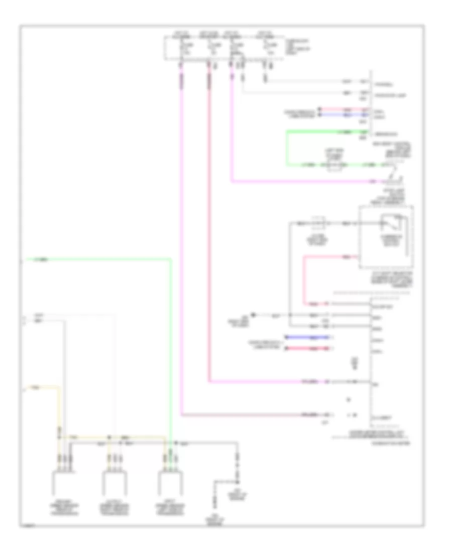
DEFOGGERS
Defoggers Wiring Diagram for Nissan Rogue S 2014
List of elements for Defoggers Wiring Diagram for Nissan Rogue S 2014:
- auto a/c
- (bottom left side of hvac unit)
- (left center of dash) j/c m03
- (upper left end of dash)
- 14r
- 16r
- A/c auto amplifier
- A/c switch
- Auto a/c
- Auto acc
- B19 (left"d"pillar)
- B29
- B54
- Bcm (body control module) (behind left end of dash)
- Can h
- Can-h
- Can-l
- Computer data line system
- D101
- D102
- D107
- D14
- D500
- D505
- D510
- D525
- Door mirror lh (door mirror defogger) (w/ heated mirrors)
- Door mirror rh (door mirror defogger) (w/ heated mirrors)
- Front air conditioner
- Fuse 10a
- Fuse 15a
- Fuse 10a
- Fuse 15a
- Fuse 5a
- Fuse block (j/b) (left end of dash)
- Gnd
- Gnd 1
- Gnd 2
- Hot at all times
- Hot in acc or on
- Hot in on or start
- I shorting pin
- Ign tempo
- J/c m18 (lower center of dash) m193
- Lin sw amp
- M125
- M127
- M158
- M167
- M168
- M18
- M19
- M193
- M20
- M44
- M50
- M51
- M54
- M57
- M57 (upper left (upper left end of dash) end of dash)
- M57 (upper left end of dash)
- M61 (right end of dash)
- M68
- M91
- O def rl d
- Pwr ecu
- Rear window defogger condenser
- Rear window defogger
- Red
- W/ auto a/c
- W/o auto a/c
ELECTRONIC POWER STEERING
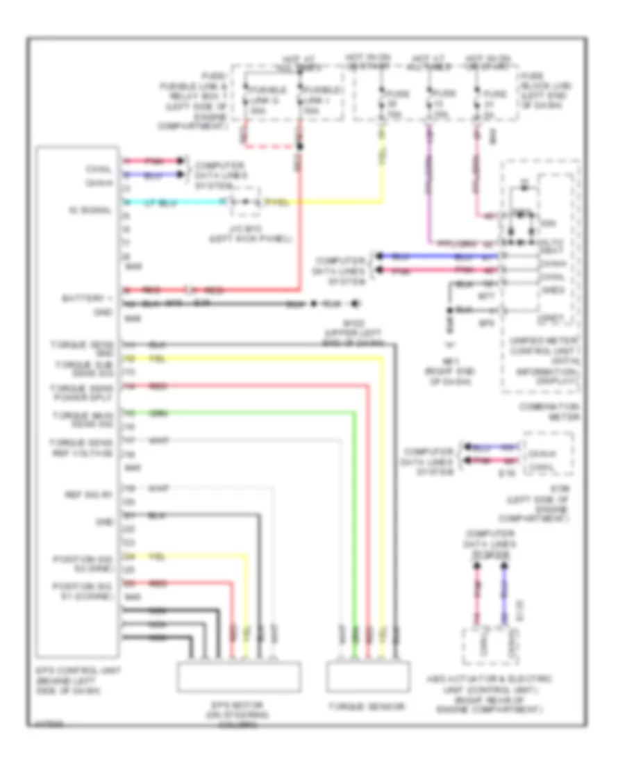
Electronic Power Steering Wiring Diagram for Nissan Rogue S 2014
List of elements for Electronic Power Steering Wiring Diagram for Nissan Rogue S 2014:
- (left side of engine compartment)
- 13p
- Abs actuator & electric
- Alvu sbat
- Battery +
- Can-h
- Can-l
- Combination meter
- Computer data lines system
- Control unit (with
- E125
- E16
- E36
- Ecm
- Eps
- Eps control unit (behind left side of dash)
- Eps motor (on steering column)
- Fuse 10a
- Fuse 5a
- Fuse block (j/b) (left end of dash)
- Fuse/ fusible link & relay box 1 (left side of engine compartment)
- Fusible link g 50a
- Fusible link i 50a
- Gnd
- Gnd1
- Gnd2
- Hot at all times
- Hot in on or start
- Ig signal
- Ign
- Information display)
- J/c m13 (left kick panel)
- M122 (upper left end of dash)
- M44
- M45
- M46
- M48
- M49
- M61 (right end of dash)
- M75
- M76
- M77
- Nca
- Pnk
- Position sig s1 (cosine)
- Position sig s2 (sine)
- Red
- Ref sig r1
- Torque main sens sig
- Torque sens
- Torque sens power sply
- Torque sens ref voltage
- Torque sensor
- Torque sub sens sig
- Unified meter
- Unit (control unit) (right rear of engine compartment)
ELECTRONIC SUSPENSION
Electronic Suspension Wiring Diagram for Nissan Rogue S 2014
List of elements for Electronic Suspension Wiring Diagram for Nissan Rogue S 2014:
- Abs actuator & electric unit (control unit) (right rear of engine compartment)
- B16
- Bcm (body control module) behind left of dash)
- Can-h
- Can-l
- Chassis control module (behind glove box)
- Combination meter
- Computer data lines system
- E120
- E125
- E16
- Ecm (left front of engine compartment)
- F42
- F75
- Fuse 30 10a
- Fuse block (j/b) (left end of dash)
- Gnd
- Hot in on or start
- Ign
- Ipdm e/r (intelligent power distribution module engine room) (left side of engine compartment)
- J/c m13 (left kick panel)
- J/c m26 (right end of dash)
- M44
- M56
- M61 (right end of dash)
- M77
- M96
- Pnk
- Steering angle sensor (on steering column)
- Tcm (transmission control module) (left rear of engine compartment)
ENGINE PERFORMANCE
2.5L
2.5L, Engine Performance Wiring Diagram (1 of 4) for Nissan Rogue S 2014
List of elements for 2.5L, Engine Performance Wiring Diagram (1 of 4) for Nissan Rogue S 2014:
- (lower right side of engine) engine oil temperature sensor
- (rear of engine) engine coolant temperature sensor
- (right side of cylinder head) fuel injectors
- (right side of engine) knock sensor
- A/f sens 1 htr
- A/f sensor 1
- Camshaft position sens (phase)
- E15 (under left headlight assembly)
- E19
- E9 (under left headlight assembly)
- Ecm gnd
- Engine control module (ecm) (left front of engine compt)
- Engine coolant temp sens
- Engine oil
- Engine oil pressure sens
- Engine oil temp sens
- Evap canister purge vol
- Exhaust valve timing control position sensor (left rear of engine)
- F33
- F51
- F52
- Flow sensor (in engine air intake duct)
- Fuel inj 1
- Fuel inj 2
- Fuel inj 3
- Fuel inj 4
- Fuel pump rly
- Heated oxygen sens 2
- Heated oxygen sens 2 htr
- Intake air temp sens
- Intake air temp sensor
- Intake manifold runner control valve (rear of intake manifold assembly)
- Intake runn ctrl mtr (close)
- Intake runn ctrl mtr (open)
- Intake runn ctrl mtr pwr sply
- Intake valve timing intermediate lock ctrl sol vlv
- Knock sens
- Mass air
- Mass air flow sens
- Pnk
- Pressure sensor (lower right front of engine)
- Red
- Sens power sply
- Sens pwr sply
- Sensor gnd
- Sensor gnd exhaust valve timing pos sens
- Shield
- Tan
- Throttle ctrl mtr (close)
- Throttle ctrl mtr (open)
- Throttle ctrl mtr rly
- Throttle ctrl mtr rly pwr sply
2.5L, Engine Performance Wiring Diagram (2 of 4) for Nissan Rogue S 2014
List of elements for 2.5L, Engine Performance Wiring Diagram (2 of 4) for Nissan Rogue S 2014:
- (top left side of transmission)
- Air fuel ratio (a/f) sensor 1 (on exhaust manifold)
- Camshaft position sensor (rear of cylinder head)
- Can h
- Can l
- Combination meter
- Computer data lines system
- E120
- E121
- E19
- Evap canister purge volume control solenoid valve (top right side of engine)
- F33
- F35
- F42
- Fuse 10a
- Fuse 15a
- Fuse 5a
- Heated oxygen sensor 2 (in exhaust downstream of catalytic converter)
- Hot at all times
- Hot in on or start
- Intake valve intermediate lock timing control solenoid valve (top right front of engine)
- Ipdm e/r (intelligent power distribution module engine room) (left side of engine compt)
- M77
- Malfunction indicator lamp
- Pnk
- Red
- Shield
- Starter relay
- Tan
- Transmission range switch
2.5L, Engine Performance Wiring Diagram (3 of 4) for Nissan Rogue S 2014
List of elements for 2.5L, Engine Performance Wiring Diagram (3 of 4) for Nissan Rogue S 2014:
- (top of cylinder head)
- 18g
- 97j
- 98j
- B136
- Computer data lines system
- Condenser
- Cpu
- E119
- E120
- E121
- E152
- E19
- Ecm relay
- Evap canister vent control valve (under right rear of vehicle)
- Exhaust valve timing control solenoid valve (left front of cylinder head)
- F33
- F35
- F42
- F53 (front of engine)
- F57 (front of engine)
- Fuel pump relay
- Fuse 10a
- Fuse 15a
- Fuse 20a
- Hot at all times
- Ignition coil 1 (w/ power transistor)
- Ignition coil 2 (w/ power transistor)
- Ignition coil 3 (w/ power transistor)
- Ignition coil 4 (w/ power transistor)
- Intake valve timing control solenoid valve (right front of cylinder head)
- Ipdm e/r (intelligent power distribution module engine room) (left side of engine compt)
- J/c f01 (left side of engine)
- M31
- M36
- Nca
- Plug 1 spark
- Plug 3 spark
- Plug 4 spark
- Pnk
- Red
- Spark plug 2
- Tan
- Throttle control motor relay
2.5L, Engine Performance Wiring Diagram (4 of 4) for Nissan Rogue S 2014
List of elements for 2.5L, Engine Performance Wiring Diagram (4 of 4) for Nissan Rogue S 2014:
- (front of intake manifold assembly) intake manifold
- (left front of engine compt) engine control module (ecm)
- (lower right rear of engine) crankshaft
- (on throttle body) electric throttle control actuator
- (under left
- (under left headlight assembly)
- 16r
- 19g
- 20g
- 21g
- 50j
- 55j
- 56j
- 57j
- 58j
- 59j
- 78g
- 79g
- 99j
- Acc pedal pos sens 1
- Acc pedal pos sens 2
- Accelerator pedal position sensor (top of accelerator pedal assembly)
- Ascd steering switch
- B132 (behind right rear quarter
- B136
- Brake pedal pos switch
- Brake pedal position switch (top of brake pedal assembly)
- Can-h
- Can-l
- Charging system
- Computer data lines system
- Crankshaft position sens (pos) sens power sply
- Cruise control system
- E15
- E152
- E16
- E19
- E28
- Ecm gnd
- Ecm rly (self shut-off)
- Evap canister vent ctrl valve
- Evap control pressure sensor (on evap canister assembly)
- Evap ctrl sys press sens
- Exhaust valve timing control sol valve
- F33
- F52
- Fuel level sensor unit and fuel pump (main) (top of fuel tank)
- Fuel pump
- Fuel tank temp sens
- Fuse 10a
- Fuse block (j/b) (left end of dash)
- Headlight assembly)
- Hot at all times
- Hot in acc or on
- Ignition signal no 1
- Ignition signal no 2
- Ignition signal no 3
- Ignition signal no 4
- Ignition switch
- Intake manifold runner ctrl vlv position sens sens power sply
- Intake valve timing control sol valve
- J/c e01 (left end of dash)
- J/c m18 (lower center of dash)
- Lin
- M31
- M36
- M68
- Panel)
- Pnk
- Pnp sig
- Position sensor
- Pwr sply for ecm
- Red
- Refrigerant press sens
- Refrigerant pressure sensor (right front of engine compt)
- Runner control valve position sensor
- Sens gnd
- Sens power sply
- Sens pwr sply
- Sensor 1
- Sensor 2
- Sensor gnd
- Shield
- Stop lamp switch
- Stop lamp switch (top of brake pedal assembly)
- Tan
- Throttle control motor
- Throttle position (tp) sensor 1
- Throttle position (tp) sensor 2
- Throttle position sens 1
- Throttle position sens 2
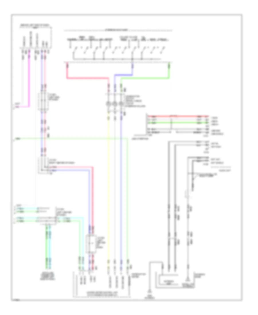
EXTERIOR LIGHTS
Backup Lamps Wiring Diagram for Nissan Rogue S 2014
List of elements for Backup Lamps Wiring Diagram for Nissan Rogue S 2014:
- 100a
- B19 (left "d" pillar)
- B40
- B46
- B54
- Back-up lamp assembly lh
- Back-up lamp assembly rh
- Cpu
- D501
- D505
- D518
- D519
- E119
- E34
- F35
- F78
- Fuse 10a
- Hot in on or start
- Ipdm e/r (intelligent power distribution module engine room) (left side of engine compartment)
- J/c b01 (left end of dash)
- Transmission range switch (top left side of transmission)
Exterior Lamps Wiring Diagram (1 of 2) for Nissan Rogue S 2014
List of elements for Exterior Lamps Wiring Diagram (1 of 2) for Nissan Rogue S 2014:
- (right center of dash)
- (upper left end of dash)
- 13p
- 14r
- 27j
- B132 (behind right rear quarter- panel)
- B140
- B16
- B19 (left "d" pillar)
- B23
- B46
- B49
- B54
- Bat
- Bcm (body control module) (behind left end of dash)
- Brake
- Buzzer
- Can-h
- Can-l
- Combination meter
- Combination switch (lighting and turn signal switch)
- Computer data lines system
- D101
- D102
- D501
- D505
- Di fr left e
- Door mirror lh
- Door mirror rh
- E152 m31
- E16
- E29
- Ecm (left front of engine compartment)
- Fuse 10a
- Fuse 5a
- Fuse block (j/b) (left end of dash)
- Gnd 1
- Gnd 2
- Hazard switch
- High mounted stop lamp
- Hot at all times
- Hot in on or start
- I brake sw2
- I csw 1
- I csw 2
- I csw 3
- I csw 4
- I csw 5
- I gnd 1
- I gnd 2
- I hazard sw d
- I pwr ecu
- I pwr flashers
- I pwr stop lamp
- I shorting pin
- Ign
- Interior lights system
- J/c b03 (behind left quarter- panel)
- J/c m26 (right end of dash)
- J/c m28
- J/c m29 (right center of dash)
- Lines system computer data
- M158
- M168
- M18
- M19
- M20
- M28
- M33
- M44
- M57
- M57 (upper left end of dash)
- M61 (right end of dash)
- M68
- M76
- M77
- M91
- Nissan eur
- O csw 1
- O csw 2
- O csw 3
- O csw 4
- O csw 5
- O di fr left d
- O di fr right d
- O di fr right e
- O di rr left b
- O di rr right b
- O stop lamp 1
- O stop lamp 2
- O stop lamp 3
- Parking brake switch (top of parking brake assembly)
- Pbk sw
- Pnk
- Red
- Rr combination lamp rh
- Stop
- Tail
- Tan
- Turn lh
- Turn rh
- Turn signal
- Unified meter control unit (with information display)
Exterior Lamps Wiring Diagram (2 of 2) for Nissan Rogue S 2014
List of elements for Exterior Lamps Wiring Diagram (2 of 2) for Nissan Rogue S 2014:
- (left end of dash)
- (under left headlight assembly)
- 10r
- 99a
- B19 (left "d" pillar)
- B29
- B40
- B46
- B54
- Back-up lamp assembly lh
- Back-up lamp assembly rh
- Computer data lines system
- Control module
- Cpu
- D501
- D505
- E103
- E105
- E119
- E120
- E121
- E15
- E15 (under left headlight assembly)
- E201
- E217
- E218
- E233
- E234
- E235
- E236
- E239
- E240
- E28
- E34
- E40
- E9 (under left headlight assembly)
- Front combination lamp lh
- Front combination lamp rh
- Fuse 10a
- Fuse block (j/b)
- Hot at all times
- Hot in on or start
- Ipdm e/r (intelligent power distribution module engine room) (left side of engine compt)
- J/c b01
- J/c b27 (behind left quarter- panel)
- J/c e01
- Led daytime,
- License plate lamp lh
- License plate lamp rh
- M68
- Parking lamp
- Pnk
- Red
- Rr combination lamp lh
- Side marker
- Smart fet
- Stop
- Stop lamp switch (top of brake pedal assembly)
- Tail
- Tan
- Turn signal
- W/ halogen headlamp
- W/ led headlamp
GROUND DISTRIBUTION
Ground Distribution Wiring Diagram (1 of 2) for Nissan Rogue S 2014
List of elements for Ground Distribution Wiring Diagram (1 of 2) for Nissan Rogue S 2014:
- 44j
- A/c auto amp
- Abs actuator & electric unit (control unit)
- Airbag diagnosis sensor unit
- Around view monitor control unit
- Audio unit
- Auto anti- dazzling inside mirror
- Automatic back door main switch
- Automatic back door switch
- Awd lock switch
- Blind spot warning indicator lh
- Blind spot warning indicator rh
- Chassis control module
- Combination switch (spiral cable)
- Cooling fan motor-2
- Cooling fan relay-3
- Cvt shift selector
- D101
- D102
- Data link connector, combination meter
- Distance sensor
- Door mirror lh
- Door mirror lh (door mirror defogger) (w/ heated mirror)
- Door mirror remote control switch
- Door mirror rh (door mirror defogger) (w/ heated mirror)
- E126 (right rear of engine compt)
- E152
- Eps control unit
- F1 (left front of engine compt)
- F2 (left front of engine compt)
- Front heated seat switch rh, front heated seat switch lh
- Front outside handle assembly lh
- Front outside handle assembly rh
- Front passenger air bag off indicator
- Glove box lamp
- Hazard switch
- Hill descent control switch
- Ignition switch
- J/c m24 (right center of dash)
- J/c m25 (lower center of dash)
- J/c m26 (right end of dash)
- J/c m27 (right end of dash)
- J/c m28 (right center of dash)
- J/c m29 (right center of dash)
- Key switch
- M122 (upper left end of dash)
- M123
- M125
- M127
- M132
- M156
- M158
- M167
- M168
- M21
- M251
- M31
- M57 (upper left end of dash)
- M61 (right end of dash)
- M91
- Main power window and door lock/unlock switch, front door lock assembly lh, door mirror lh, door mirror remote control switch
- Map lamp assembly
- Meter control switch
- Moon roof motor assembly
- Moonroof switch
- Nats antenna amp (w/o intelligent key system), combination switch, dongle unit, bcm (body control module), front air control, a/c switch,
- Nca
- Personal lamps 2nd row (w/ moon roof), room lamp (w/o moon roof), map lamp assembly, vanity mirror lamp rh, vanity mirror lamp lh
- Pnk
- Power window and door lock/unlock switch rh
- Push button ignition switch
- R11
- R12
- R13
- Sport mode switch
- Steering angle sensor, front power socket, console power socket, audio unit, av control unit, front heated seat switch rh, front heated seat switch lh
- Sunshade motor assembly
- Variable blower control
- Vdc off switch
- Warning system buzzer
- Warning system switch
- Warning systems switch
Ground Distribution Wiring Diagram (2 of 2) for Nissan Rogue S 2014
List of elements for Ground Distribution Wiring Diagram (2 of 2) for Nissan Rogue S 2014:
- 13j
- 14j
- 79j
- A/c compressor, input speed sensor, tcm (transmission control module), primary speed sensor, output speed sensor
- Air bag diagnosis sensor unit
- Air bag diagnosis sensor unit (shield wire), front side air bag satellite sensor lh shield
- Air bag diagnosis sensor unit (shield wire), front side air bag satellite sensor rh shield
- Air bag diagnosis sensor unit (shield wire), rear side satellite sensor lh shield
- Air bag diagnosis sensor unit (shield wire), rear side satellite sensor rh shield
- Automatic back door control module, back door warning chime, rear view camera washer control unit, awd control unit, rear combination lamp lh turn signal
- B112 (right "b" pillar)
- B117 (under front passenger's seat)
- B127
- B132 (behind right rear quarter panel)
- B134
- B19 (left "d" pillar)
- B202
- B300
- B33 (base of left "b" pillar)
- B350
- B54
- B7 (under driver's seat)
- B92
- Back door opener switch, back-up lamp assembly lh, back-up lamp assembly rh
- Brake fluid level switch, front combination lamp rh turn signal
- Condenser
- Crash zone sensor shield
- D505
- E11 (right side of engine compt)
- E15 (under left headlight assembly)
- E152
- E19
- E201
- E40
- E9 (under left headlight assembly)
- Ecm
- Ecm, horn (low),
- F33
- F53 (front of engine)
- F57 (front of engine)
- Front combination lamp lh (w/ led headlamp) front combination lamp lh high and low beam, front combination lamp rh high beam (w/ halogen headlamp)
- Front combination lamp rh
- Front combination lamp rh (w/ led headlamp) front combination lamp rh low beam (w/ halogen headlamp)
- Front door satellite sensor lh shield
- Front door satellite sensor rh shield
- Front wiper motor, horn (high), washer fluid level switch, front combination lamp lh turn signal,
- Fuel level sensor unit and fuel pump (main)
- Ignition coil 1 (w/ power transistor)
- Ignition coil 2 (w/ power transistor)
- Ignition coil 3 (w/ power transistor)
- Ignition coil 4 (w/ power transistor)
- Intake manifold runner control control valve shield
- Intelligent key warning buzzer
- Ipdm e/r (intelligent power distribution module engine room)
- J/c b26 (left "c" pillar)
- J/c b30 (right "c" pillar)
- J/c f01 (left side of engine)
- J/c m31 (right end of dash)
- Lh side curtain airbag module shield
- M159
- M169
- M31
- Occupant classification system control unit
- Pnk
- Power seat switch lh, seat cushion heater lh, lumbar support switch
- Power seat switch rh, seat cushion heater rh
- Rh side curtain airbag module shield
- Seat belt buckle switch lh
- Seat belt buckle switch rh
- Shield
- Subwoofer, bose speaker amp.
HEADLIGHTS
Headlamp Aiming Wiring Diagram, with LED Headlamps for Nissan Rogue S 2014
List of elements for Headlamp Aiming Wiring Diagram, with LED Headlamps for Nissan Rogue S 2014:
- 13p
- 14r
- 75a
- 76a
- 77a
- Amp
- B16
- B40
- Bat
- Bcm (body control module) (behind left end of dash)
- Can-h
- Can-l
- Combination meter
- Combination switch (lighting and turn signal switch)
- Computer data lines system
- Cpu
- E119
- E120
- E121
- E15 (under left headlight assembly)
- E217
- E218
- E34
- Front combination lamp lh (headlamp aiming motor)
- Front combination lamp rh (headlamp aiming motor)
- Fuse 10a
- Fuse 5a
- Fuse block (j/b) (left end of dash)
- Gnd1
- Gnd2
- Hot at all times
- Hot in on or start
- I csw 1
- I csw 2
- I csw 3
- I csw 4
- I csw 5
- I gnd1
- I gnd2
- I pwr ecu
- I shorting pin
- Ign
- Ignition relay-1
- Ipdm e/r (intelligent power distribution module engine room) (left side of engine compartment)
- M18
- M19
- M20
- M44
- M57 (upper left end of dash)
- M61 (right end of dash)
- M68
- M76
- M77
- O csw 1
- O csw 2
- O csw 3
- O csw 4
- O csw 5
- Pnk
- Rear height sensor (right rear wheelwell)
- Tan
- Unified meter control unit (with information display)
Headlamps Wiring Diagram, with Halogen Headamps (1 of 2) for Nissan Rogue S 2014
List of elements for Headlamps Wiring Diagram, with Halogen Headamps (1 of 2) for Nissan Rogue S 2014:
- 13p
- 14r
- B140
- B16
- B19 (left "d" pillar)
- B46
- B49
- B54 d505
- Back door lock assembly (bottom center of back door)
- Bat
- Bcm (body control module) (behind left end of dash)
- Can-h
- Can-l
- Combination meter
- Combination switch (lighting and turn signal switch)
- Computer data lines system
- D501
- D508
- D512
- Fog lamp
- Front door switch lh (left "b" pillar)
- Front door switch rh (right "b" pillar)
- Fuse 10a
- Fuse 5a
- Fuse block (j/b) (left end of dash)
- Gnd1
- Gnd2
- Hot at all times
- Hot in on or start
- I as door 2 sw
- I autolight sens o gnd autolight sens m18
- I csw 1
- I csw 2
- I csw 3
- I csw 4
- I csw 5
- I dr door 2 sw
- I gnd1
- I gnd2
- I pwr ecu
- I rl door sw
- I rr door sw
- I shorting pin
- I tgate sw
- Ign
- Light (green)
- M18
- M19
- M20
- M28
- M44
- M57 (upper left end of dash)
- M61 (right end of dash)
- M68
- M76
- M77
- O csw 1
- O csw 2
- O csw 3
- O csw 4
- O csw 5
- O pwr autolight sens
- Optical sensor (top left end of dash)
- Pnk
- Rear door switch lh (left "c" pillar)
- Rear door switch rh (right "c" pillar)
- Red
- Tan
- Unified meter control unit (with information display)
- W/ power back door
- W/o power back door
Headlamps Wiring Diagram, with Halogen Headamps (2 of 2) for Nissan Rogue S 2014
List of elements for Headlamps Wiring Diagram, with Halogen Headamps (2 of 2) for Nissan Rogue S 2014:
- Computer data lines system
- Cpu
- E119
- E120
- E121
- E15 (under left headlight assembly)
- E15 (under left headlight assembly)
- E201
- E217
- E218
- E233
- E234
- E235
- E236
- E40
- E9 (under left headlight assembly)
- Front combination lamp lh
- Front combination lamp rh
- Front fog lamp lh
- Front fog lamp rh
- High beam
- Hot at all times
- Hot in on or start
- Ipdm e/r (intelligent power distribution module engine room) (left side of engine compartment)
- Low beam
- Pnk
- Smart fet
Headlamps Wiring Diagram, with LED Headlamps (1 of 2) for Nissan Rogue S 2014
List of elements for Headlamps Wiring Diagram, with LED Headlamps (1 of 2) for Nissan Rogue S 2014:
- 13p
- 14r
- B140
- B16
- B19 (left "d" pillar)
- B46
- B49
- B54 d505
- Back door lock assembly (bottom center of back door)
- Bat
- Bcm (body control module) (behind left end of dash)
- Can-h
- Can-l
- Combination meter
- Combination switch (lighting and turn signal switch)
- Computer data lines system
- D501
- D508
- D512
- Fog lamp
- Front door switch lh (left "b" pillar)
- Front door switch rh (right "b" pillar)
- Fuse 10a
- Fuse 5a
- Fuse block (j/b) (left end of dash)
- Gnd1
- Gnd2
- Hot at all times
- Hot in on or start
- I as door 2 sw
- I autolight sens o gnd autolight sens m18
- I csw 1
- I csw 2
- I csw 3
- I csw 4
- I csw 5
- I dr door 2 sw
- I gnd1
- I gnd2
- I pwr ecu
- I rl door sw
- I rr door sw
- I shorting pin
- I tgate sw
- Ign
- Light (green)
- M18
- M19
- M20
- M28
- M44
- M57 (upper left end of dash)
- M61 (right end of dash)
- M68
- M76
- M77
- O csw 1
- O csw 2
- O csw 3
- O csw 4
- O csw 5
- O pwr autolight sens
- Optical sensor (top left end of dash)
- Pnk
- Rear door switch lh (left "c" pillar)
- Rear door switch rh (right "c" pillar)
- Red
- Tan
- Unified meter control unit (with information display)
- W/ power back door
- W/o power back door
Headlamps Wiring Diagram, with LED Headlamps (2 of 2) for Nissan Rogue S 2014
List of elements for Headlamps Wiring Diagram, with LED Headlamps (2 of 2) for Nissan Rogue S 2014:
- Computer data lines system
- Cpu
- E119
- E120
- E121
- E15 (under left headlight assembly)
- E15 (under left headlight assembly)
- E201
- E217
- E218
- E40
- E9 (under left headlight assembly)
- Front combination lamp lh
- Front combination lamp rh
- Front fog lamp lh
- Front fog lamp rh
- High beam
- Hot at all times
- Hot in on or start
- Ipdm e/r (intelligent power distribution module engine room) (left side of engine compartment)
- Led headlamp control module
- Low beam
- Pnk
- Smart fet
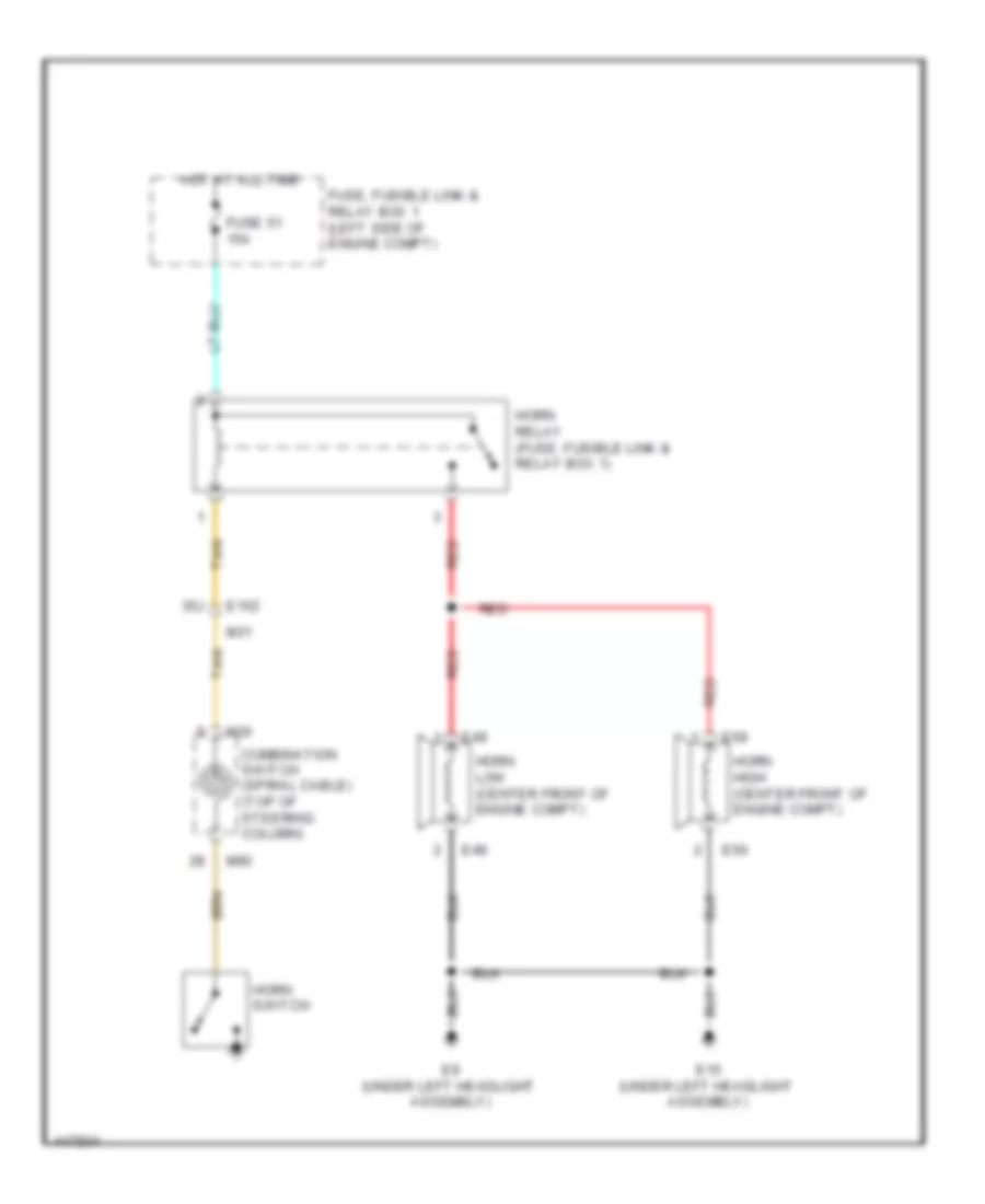
HORN
Horn Wiring Diagram for Nissan Rogue S 2014
List of elements for Horn Wiring Diagram for Nissan Rogue S 2014:
- 35j
- Combination switch (spiral cable) (top of steering column)
- E15 (under left headlight assembly)
- E152
- E48
- E49
- E50
- E69
- E9 (under left headlight assembly)
- Fuse 51 15a
- Fuse, fusible link & relay box 1 (left side of engine compt)
- Horn high (center front of engine compt)
- Horn low (center front of engine compt)
- Horn relay (fuse, fusible link & relay box 1)
- Horn switch
- Hot at all time
- M30
- M31
- M90
- Red
- Tan
INSTRUMENT CLUSTER
Instrument Cluster Wiring Diagram (1 of 2) for Nissan Rogue S 2014
List of elements for Instrument Cluster Wiring Diagram (1 of 2) for Nissan Rogue S 2014:
- (behind left end of dash) bcm (body control module)
- (behind left side of front grille)
- (left "b" pillar) driver front door switch
- (left "c" pillar) left rear door switch
- (right "b" pillar) passenger front door switch
- (right "c" pillar) right rear door switch
- (spiral cable)
- (top of parking
- (top of steering
- 26j
- 27j
- 28j
- 29j
- 2p/r out
- 30j
- 8p/r out
- Ambient sensor
- Assembly)
- B140
- B16
- B19 (left "d" pillar)
- B49
- Back
- Back door lock assembly (door ajar switch)
- Brake assembly)
- Brake fluid level switch (in master brake fluid reservoir)
- Brake oil sw
- Can-h
- Can-l
- Column)
- Combination meter
- Combination switch
- D501 b46
- D508
- D512
- Display
- Down
- Dr belt sw
- Dr sw fl
- Dr sw pass
- Dr sw rl
- Dr sw rr
- E15 (under left headlight
- E152
- E9 (under left headlight
- End of dash)
- Enter
- From combination meter (diagram 2 of 2)
- Gnd1
- Ill down sw
- Ill up sw
- Illumination
- J/c m28 (right center of dash)
- J/c m29 (right center of dash)
- M18
- M30
- M31
- M57 (upper left
- M57 (upper left end of dash)
- M61 (right end of dash)
- M76
- M90
- Menu down
- Menu up
- Meter control switch
- O/d off sw
- Outside temp gnd
- Outside temp sensor
- Parking brake switch
- Pkb sw
- Pnk
- Power tops system
- Red
- Satellite sw gnd
- Security
- Security led
- Sound/ navigation systems
- Source
- Speedo meter meter meter
- Sport mode sw
- Sport mode switch
- Steering switches
- Strg sw gnd
- Strg sw input1
- Strg sw input2
- Tacho meter
- Tan
- Tel off
- Tgate sw
- To interior lights
- Trip reset
- Trip reset sw
- Unified meter control unit (with information display)
- Volume down
- Volume up
- Washer fluid level switch (in washer fluid reservoir)
- Washer sw
- With power back door
- Without power back door
Instrument Cluster Wiring Diagram (2 of 2) for Nissan Rogue S 2014
List of elements for Instrument Cluster Wiring Diagram (2 of 2) for Nissan Rogue S 2014:
- (left center of dash) j/c m02
- (left end of dash)
- (left front of engine)
- (lower right front of engine)
- (right
- (right end of dash)
- (right rear of engine compt)
- (under front passenger seat)
- (w/ all wheel drive)
- (w/ front fog lamps)
- 13p
- 61j
- 62j
- 80g
- 81g
- Abs
- Abs actuator & electric unit (control unit)
- Air bag diagnosis sensor unit (under center
- Airbag
- Awd auto
- Awd lock
- B103
- B104
- B113
- B117
- B136
- B300 b134
- B41
- B7 (under driver's seat)
- B78
- Bat
- Belt
- Brake
- Buckle sw fr lh
- Buckle sw fr rh
- Buzzer
- Can-h
- Can-l
- Center of dash)
- Charge
- Combination meter
- Computer data lines system
- Console)
- Cpu
- Cvt shift selector (base of shift lever assembly)
- Door sill)
- Driver side front seat
- Driver side seat belt buckle switch
- E120
- E125
- E152
- E16
- Ecm (left side of engine compt)
- Engine oil pressure sensor
- Eps
- Eps control module (behind left side of dash)
- F42
- F51
- F52
- F75
- Fog light
- Fuel gauge
- Fuel level sensor unit & fuel pump (fuel level sensor) (at fuel tank)
- Fuel level sensor unit (sub)
- Fuel sens
- Fuel sens gnd
- Fuse 10a
- Fuse 5a
- Fuse block (j/b) (left end of dash)
- Generator
- Gnd2
- Hill descent ctrl
- Hill start assist
- Hot at all times
- Hot in on or start
- Ign
- Illum o/p
- Interior lights system
- Ipdm e/r (intelligent power distribution module engine room) (left side of engine compt)
- J/c b01
- J/c b01 (left end of dash)
- J/c b29 (under front
- J/c e01
- J/c m01
- J/c m26
- Light (green)
- Lin
- M can-h
- M can-l
- M10
- M31
- M36
- M44
- M49
- M61 (right end of dash)
- M69
- M77
- Master (red or
- Meter illumination
- Mil
- O/d off
- O/d off switch
- Oilpres
- Oilpres avcc2
- Oilpres gnd
- Passenger side front seat
- Passenger side seat belt buckle switch
- Passenger's
- Pnk
- Red
- Slip
- Sound/ navigation systems
- Sport
- T0 security led (diagram 1 of 2)
- Tcm (left rear of engine compt)
- Tire pressure
- Turn lh
- Turn rh
- Unified meter control unit (with information display)
- Vdc off
- Water temp gauge
INTERIOR LIGHTS
Courtesy Lamps Wiring Diagram, with Intelligent Key for Nissan Rogue S 2014
List of elements for Courtesy Lamps Wiring Diagram, with Intelligent Key for Nissan Rogue S 2014:
- (right center of dash) j/c m29
- (right end of dash) m61
- 100g
- 14r
- 95g
- Automatic back door close switch (bottom left of back door) (w/ power back door)
- B136
- B16
- B19 (left "d" pillar)
- B23
- B42
- B46 d501
- B47
- B49 b140
- B54
- Back door lock assembly (bottom center of back door)
- Bcm (body control module) (behind left end of dash)
- Can-h
- Can-l
- Computer data lines system
- D101
- D101 m91
- D502
- D505
- D508
- D512
- Door
- Front door lock assembly lh
- Front door switch lh (in left side "b" pillar)
- Front door switch rh (in right side "b" pillar)
- Front outside handle assembly lh
- Front outside handle assembly rh
- Front power window switch rh
- Fuse 10a
- Fuse 20a
- Fuse 5a
- Fuse block (j/b) (left end of dash)
- Gnd
- Hot at all times
- I as door2 sw
- I doorlock sw
- I doorunlock sw
- I dr door2 sw
- I dr knob sw
- I gnd 1
- I gnd 2
- I pwr ecu
- I rl door sw
- I rr door sw
- I ses dr handle button sw
- I ses fr handle button sw
- I shorting pin
- I start wo ecsl sw
- I tgate sw
- Interior switch (all)
- Interior switch (door)
- J/c m26 (right end of dash)
- J/c m30 (right center of dash)
- Lamp switch rh
- Lock
- Luggage room lamp
- M156
- M167
- M167 d2
- M168
- M168 d3
- M18
- M19
- M20
- M21
- M33
- M36
- M57 (upper left end of dash)
- M61 (right end of dash)
- M68
- M74
- M91
- M91 d101
- Main power window and door lock/ unlock switch
- Map lamp assembly
- N n
- O pwm roomlamp 1
- O pwm roomlamp 5
- O spare4 rl n
- O start sw backlight led
- Off
- Off lamp switch lh
- Personal lamp lh
- Personal lamp rh
- Personal lamps 2nd row (w/ moon roof)
- Pnk
- Push button ignition switch
- R1 m21
- R11
- Rear door switch lh (in left side "c" pillar)
- Rear door switch rh (in right side "c" pillar)
- Red
- Room lamp (w/o moon roof)
- Room lamp relay (lower center of dash)
- Tan
- Unlock
- Vanity mirror lamp lh
- Vanity mirror lamp rh
- W/ power back door
- W/o power back door
Courtesy Lamps Wiring Diagram, without Intelligent Key for Nissan Rogue S 2014
List of elements for Courtesy Lamps Wiring Diagram, without Intelligent Key for Nissan Rogue S 2014:
- (right center of dash) j/c m29
- (right end of dash) m61
- 100g
- 14r
- 95g
- Automatic back door close switch (bottom left of back door) (w/ power back door)
- B136
- B16
- B19 (left "d" pillar)
- B23
- B42
- B46 d501
- B47
- B49 b140
- B54
- Back door lock assembly (bottom center of back door)
- Bcm (body control module) (behind left end of dash)
- Can-h
- Can-l
- Computer data lines system
- D101 m91
- D502
- D505
- D508
- D512
- Door
- Front door lock assembly lh
- Front door switch lh (in left side "b" pillar)
- Front door switch rh (in right side "b" pillar)
- Front power window switch rh
- Fuse 10a
- Fuse 20a
- Fuse 5a
- Fuse block (j/b) (left end of dash)
- Gnd
- Hot at all times
- I as door2 sw
- I doorlock sw
- I doorunlock sw
- I dr door2 sw
- I dr knob sw
- I gnd 1
- I gnd 2
- I ign sw
- I key sw
- I pwr ecu
- I rl door sw
- I rr door sw
- I shorting pin
- I starter sw
- I tgate sw
- Ignition switch
- Interior switch (all)
- Interior switch (door)
- J/c m26 (right end of dash)
- J/c m30 (right center of dash)
- Key switch
- Lamp switch lh
- Lamp switch rh
- Lock
- Luggage room lamp
- M156
- M167
- M167 d2
- M168 d3
- M18
- M19
- M20
- M21
- M33
- M36
- M57 (upper left end of dash)
- M61 (right end of dash)
- M68
- M74
- M91 d101
- Main power window and door lock/ unlock switch
- Map lamp assembly
- O pwm roomlamp 1
- O pwm roomlamp 5
- O spare4 rl n
- Off
- Personal lamp lh
- Personal lamp rh
- Personal lamps 2nd row (w/ moon roof)
- Pnk
- R11
- Rear door switch lh (in left side "c" pillar)
- Rear door switch rh (in right side "c" pillar)
- Red
- Room lamp (w/o moon roof)
- Room lamp relay (lower center of dash)
- Tan
- Unlock
- Vanity mirror lamp lh
- Vanity mirror lamp rh
- W/ power back door
- W/o power back door
Instrument Illumination Wiring Diagram (1 of 2) for Nissan Rogue S 2014
List of elements for Instrument Illumination Wiring Diagram (1 of 2) for Nissan Rogue S 2014:
- (left end of dash)
- (right center of dash) j/c m29
- (w/ autolight system) (top left end of dash) optical sensor
- (w/ driver assistance system)
- (w/ power back door)
- 13p
- 14r
- Alvusbat
- Audio unit (w/o navigation)
- Automatic back door main switch
- Automatic back door switch (w/power back door)
- Av control unit (w/ navigation)
- B16
- Body control module (bcm) (behind left end of dash)
- Can-h
- Can-l
- Combination meter
- Combination switch (lighting and turn signal switch)
- Combination switch (spiral cable)
- Computer data lines system
- Cpu
- D27
- Door mirror remote control switch
- E119
- E120
- E121
- E15 (under left headlight assembly)
- E28
- Fuse 10a
- Fuse 5a
- Fuse block (j/b)
- Gnd 1
- Gnd 2
- Hazard switch
- Hot at all times
- Hot in on or start
- I autolight sens
- I csw 1
- I csw 2
- I csw 3
- I csw 4
- I csw 5
- I gnd1
- I gnd2
- I pwr ecu
- I shorting pin
- Ign
- Ill cont out
- Ill down sw
- Ill up sw
- Illumination
- Ipdm e/r (intelligent power distribution module engine room) (left side of engine compartment)
- J/c m27 (right end of dash)
- J/c m28 (right center of dash)
- J/c m29 (right center of dash)
- J/c m33 (left kick panel)
- M101
- M108
- M13
- M168
- M18
- M19
- M20
- M251
- M28
- M30
- M44
- M57 (upper left end of dash)
- M61 (right end of dash)
- M68
- M76
- M77
- M83
- M90
- Meter control switch
- Meter ill
- O csw 1
- O csw 2
- O csw 3
- O csw 4
- O csw 5
- O gnd autolight sens
- O pwr autolight sens
- Pnk
- Red
- Sat sw gnd
- Smart fet
- Steering switches
- Tan
- Unified meter control unit (with information display)
- W/bose audio
- W/o bose audio
- Warning system switch
Instrument Illumination Wiring Diagram (2 of 2) for Nissan Rogue S 2014
List of elements for Instrument Illumination Wiring Diagram (2 of 2) for Nissan Rogue S 2014:
- Assembly
- Awd lock switch (w/ all wheel drive)
- Cvt shift selector (base of shift lever assembly)
- Front heated seat switch lh (w/ front heated seat)
- Front heated seat switch rh (w/ front heated seat)
- Glove box
- Hill descent control switch
- J/c m26 (right end of dash)
- J/c m27 (right end of dash)
- J/c m28 (right center of dash)
- J/c m29 (right center of dash)
- J/c m34 (right end of dash)
- Lamp
- M156
- M251
- M57 (upper left end of dash)
- M61 (right end of dash)
- Map lamp
- Pnk
- R11
- Red
- Sport mode switch
- Vdc off switch
NAVIGATION
Navigation Wiring Diagram, Base (1 of 3) for Nissan Rogue S 2014
List of elements for Navigation Wiring Diagram, Base (1 of 3) for Nissan Rogue S 2014:
- (right center of dash) j/c m06
- 100a
- 94g
- 99g m36
- Acc
- Aux gnd
- Aux in jack
- Aux l
- Aux r
- Av control unit
- B136
- B40
- B41
- B42
- B51
- Battery
- Can h
- Can l
- Computer data lines system
- Cpu
- D102
- D2 m167
- D201
- D301 b101
- E119
- E34
- End of dash)
- F35
- Fr sp lh (+)
- Fr sp lh (-)
- Fr sp rh (+)
- Fr sp rh (-)
- Front
- Front door speaker lh
- Front door speaker rh
- Front tweeter rh
- Fuse 10a
- Gnd
- Hot in on or start
- Ignition
- Ill (+) light sw
- Interior lights system
- Ipdm e/r (intelligent power distribution module engine room) (left side of engine compt)
- J/c m05 (right center of dash)
- M-can termination
- M101
- M102
- M104
- M138
- M156
- M158
- M57 (upper left
- M69
- M74
- M89
- Mcan+
- Mcan-
- Mic gnd
- Mic sig
- Mic vcc
- Microphone (in roof console)
- Mr output
- Of transmission)
- Pnk
- R11
- Rear door speaker lh
- Red
- Reverse
- Rr sp lh (+)
- Rr sp lh (-)
- Rr sp rh (+)
- Rr sp rh (-)
- Shield
- Speed signal
- Sub out/aux shield
- Tan
- Transmission range switch (top left side
- Tweeter lh
- Usb d+
- Usb d-
- Usb gnd
- Usb interface
- Usb shield
- V bus
Navigation Wiring Diagram, Base (2 of 3) for Nissan Rogue S 2014
List of elements for Navigation Wiring Diagram, Base (2 of 3) for Nissan Rogue S 2014:
- (behind left end of dash) bcm
- (top of steering column)
- 10m
- 14r
- 8p/r out
- B16
- B41
- Back
- Buzzer
- Can-h
- Can-l
- Combination meter
- Combination switch (spiral cable)
- Computer data
- Data link connector (under left side of dash)
- Display
- E28
- Enter
- Fuse 10a
- Fuse 15a
- Fuse 20a
- Fuse 5a
- Fuse, fusible link & relay box (left end of dash)
- Hot at all times
- Hot in on or start
- I pwr ecu
- I shorting pin
- J/c b01 (left end
- J/c m01 (right center of dash)
- J/c m02 (left center of dash)
- J/c m04 (left center of dash)
- Light sensor
- Lines system
- M-can h
- M-can l
- M18
- M19
- M20
- M22
- M30
- M44
- M47
- M68
- M69
- M76
- M77
- M90
- Menu down
- Menu menu up up
- O auto acc2
- O gnd auto-
- Of dash)
- Pnk
- Red
- Source
- Steering switches
- Stg sw gnd
- Stg sw ip1
- Stg sw ip2
- Tan
- Tel off
- Unified meter control unit (with information display)
- Volume down
- Volume up
Navigation Wiring Diagram, Base (3 of 3) for Nissan Rogue S 2014
List of elements for Navigation Wiring Diagram, Base (3 of 3) for Nissan Rogue S 2014:
- (left rear of luggage compartment) rear view camera washer control unit
- 22j
- 23j
- 24j
- 25j
- 33j
- 34j
- 44j
- 45j
- Ant b+
- Ant main
- Antenna amp
- Antenna base
- Around view monitor control unit (behind glove box)
- Av control unit
- B19 (left "d" pillar)
- B40
- B40 e34
- B46 d501
- Blind spot warning indicator lh
- Blind spot warning indicator rh
- Buzzer cont
- Camera +
- Camera -
- Camera - (shield)
- Camera washer +
- Can-h
- Can-l
- Computer data lines system
- D107
- D108
- D14
- D504
- D514
- Distance sensor (w/ forward collision warning system) (behind right side of front grille)
- Door mirror lh
- Door mirror rh
- E21
- E226
- E26 e209
- E34
- Fr camera c/u to pump
- From c/u to pump
- From pump to c/u
- From pump to camera c/u
- Front camera (behind center of front grille)
- Fv power 6.2v
- Fv power gnd
- Fv video gnd
- Fv video signal
- Gnd
- Gps ant
- Gps antenna
- Gps shield
- Ign
- Indicator l
- Indicator r
- Its sw
- Its sw indicator
- J/c m13 (left kick panel)
- J/c m24 (right center
- J/c m26 (right end of dash)
- M102
- M103
- M113
- M114
- M120
- M129
- M130
- M139
- M141
- M142
- M167 d2
- M168 d3
- M251
- M253
- M31 e152
- M500
- M501
- M502
- M503
- M57 (upper left end of dash)
- M61 (right end of dash)
- M69 b41
- M9 m251
- M91 d101
- Of dash)
- Pnk
- Pump motor +
- Pump motor -
- Rear view camera (center of back door)
- Rear view camera air pump motor (behind left side of rear bumper)
- Rear view camera washer motor (on washer fluid reservoir)
- Red
- Rod antenna
- Rv power 6.2v
- Rv power gnd
- Rv serial signal
- Rv video gnd
- Rv video signal
- Sat ant
- Sat shield
- Satellite antenna
- Shield
- Signal gnd
- Sv1 power 6.2v
- Sv1 power gnd
- Sv1 video gnd
- Sv1 video sgnl
- Sv2 power 6.2v
- Sv2 power gnd
- Sv2 video gnd
- Sv2 video sgnl
- Tan
- Video out gnd
- Video out signal
- Warning system buzzer
- Warning system switch
- With driver assistance system
- With forward collision warning system
- Without driver assistance system
Navigation Wiring Diagram, Bose (1 of 3) for Nissan Rogue S 2014
List of elements for Navigation Wiring Diagram, Bose (1 of 3) for Nissan Rogue S 2014:
- (under front passe- nger's seat)
- 100a
- 10g
- 14p
- 15p
- 34g
- 35g
- 36g
- 37g
- 38g
- 39g
- 40g
- 41g
- 44g
- 45g
- 46g
- 47g
- 48g
- 49g
- 50g
- 80mm twid+)
- 91g
- 92g
- 93g
- 96g
- 97g
- 98g
- Acc
- Amp on
- Aux gnd
- Aux l
- Aux r
- Av control unit
- B101 d301
- B106
- B116
- B117
- B117 (under front passenger's seat)
- B136
- B137
- B138
- B140
- B40
- B41
- B49
- B51
- Battery
- Bose speaker amp (under front pass- enger's seat)
- Can h
- Can l
- Center speaker
- Computer data lines system
- Computer data lines system interior lights system
- D102
- D201
- E34
- Enable) gpio d(ext amp
- End of dash)
- Fr sp lh (+)
- Fr sp lh (-)
- Fr sp rh (+)
- Fr sp rh (-)
- Front door
- Front tweeter lh
- Fuse 10a
- Fuse 20a
- Fuse block j/b (left end of dash)
- Gnd
- Hot at all times
- Ignition
- Ill (+),light sw
- In 1+(fr lt in+)
- In 1-(fr lt in-)
- In 2+(fr rt in+)
- In 2-(fr rt in-)
- In 3+(rr lt in+)
- In 3-(rr lt in-)
- In 4+(rr rt in+)
- In 4-(rr rt in-)
- J/c m22 (right end of dash)
- M-can termination
- M108
- M109
- M138
- M156
- M158
- M167
- M36
- M44
- M57 (upper left
- M69
- M89
- Mcan+
- Mcan-
- Mic gnd
- Mic sig
- Mic vcc
- Mr output
- Out 1+(ip lt1 tweeter+)
- Out 1-(ip lt1 tweeter-)
- Out 3+(ip cent
- Out 4+(stbb sgnl)
- Out 4-(stbb sgnl)
- Out 5+(fr lt dr sp+)
- Out 5-(fr lt dr sp-)
- Out 6+(fr rt dr sp+)
- Out 6-(fr rt dr sp-)
- Out 7+(rr lt dr sp+)
- Out 7-(rr lt dr sp-)
- Out 8+(rr rt dr sp+)
- Out 8-(rr rt dr sp-)
- Pnk
- Pre amp shield
- R11
- Rear door speaker lh
- Rear door speaker rh
- Red
- Reverse
- Rr sp lh (+)
- Rr sp lh (-)
- Rr sp rh (+)
- Rr sp rh (-)
- Shield
- Speaker lh
- Speaker rh
- Speed signal
- Sub out/aux shield
- Subwoofer
- Swb+
- Tan
- Tweeter+) out 2+ (ip rt 1
- Tweeter-) out 2-(ip rt 1 twid) out 3-(ip cent 80mm
- Usb d+
- Usb d-
- Usb gnd
- Usb interface
- Usb shield
- V bus
Navigation Wiring Diagram, Bose (2 of 3) for Nissan Rogue S 2014
List of elements for Navigation Wiring Diagram, Bose (2 of 3) for Nissan Rogue S 2014:
- (top left side of
- (top of steering column)
- (under left side of
- 10m
- 14r
- 8p/r out
- Aux in jack
- B16
- B41
- Back
- Bcm (behind left end of dash)
- Buzzer
- Can-h
- Can-l
- Center of dash)
- Combination meter
- Combination switch (spiral cable)
- Computer data
- Cpu
- Dash)
- Data link connector
- Display
- E28
- Enter
- F35
- Fuse 10a
- Fuse 15a
- Fuse 20a
- Fuse 5a
- Fuse block j/b (left end of dash)
- Hot at all times
- Hot in on or start
- I pwr ecu
- I shorting pin
- Ipdm e/r (intelligent power distribution module engine room) (left side of engine compt) e119
- J/c b01 (left end of dash)
- J/c m01 (right center of dash)
- J/c m02 (left
- J/c m04 (left center of dash)
- Lines system
- M-can h
- M-can l
- M104
- M18
- M19
- M20
- M22
- M30
- M44
- M68
- M69
- M76
- M77
- M90
- Menu down
- Menu up
- Microphone (in roof console)
- O auto acc2
- O gnd auto- light sensor
- Pnk
- Red
- Shield
- Source
- Steering switches
- Stg sw gnd
- Stg sw ip1
- Stg sw ip2
- Tan
- Tel off
- Transmission range switch
- Transmission)
- Unified meter control unit (with information display)
- Volume down
- Volume up
Navigation Wiring Diagram, Bose (3 of 3) for Nissan Rogue S 2014
List of elements for Navigation Wiring Diagram, Bose (3 of 3) for Nissan Rogue S 2014:
- (left rear of luggage compartment) rear view camera washer control unit
- 22j
- 23j
- 24j
- 25j
- 33j
- 34j
- 44j
- 45j
- Ant b+
- Ant main
- Antenna amp
- Antenna base
- Around view monitor control unit (behind glove box)
- Av control unit
- B19 (left "d" pillar)
- B40
- B40 e34
- B46 d501
- Blind spot warning indicator lh
- Blind spot warning indicator rh
- Buzzer cont
- Camera +
- Camera -
- Camera - (shield)
- Camera washer +
- Can-h
- Can-l
- Computer data lines system
- D107
- D108
- D14
- D504
- D514
- Distance sensor (w/ forward collision warning system) (behind right side of front grille)
- Door mirror lh
- Door mirror rh
- E21
- E226
- E26 e209
- E34
- Fr camera c/u to pump
- From c/u to pump
- From pump to c/u
- From pump to camera c/u
- Front camera (behind center of front grille)
- Fv power 6.2v
- Fv power gnd
- Fv video gnd
- Fv video signal
- Gnd
- Gps ant
- Gps antenna
- Gps shield
- Ign
- Indicator l
- Indicator r
- Its sw
- Its sw indicator
- J/c m13 (left kick panel)
- J/c m24 (right center
- J/c m26 (right end of dash)
- M103
- M109
- M113
- M114
- M120
- M129
- M130
- M139
- M141
- M142
- M167 d2
- M168 d3
- M251
- M253
- M31 e152
- M500
- M501
- M502
- M503
- M57 (upper left end of dash)
- M61 (right end of dash)
- M69 b41
- M9 m251
- M91 d101
- Of dash)
- Pnk
- Pump motor +
- Pump motor -
- Rear view camera (center of back door)
- Rear view camera air pump motor (behind left side of rear bumper)
- Rear view camera washer motor (on washer fluid reservoir)
- Red
- Rod antenna
- Rv power 6.2v
- Rv power gnd
- Rv serial signal
- Rv video gnd
- Rv video signal
- Sat ant
- Sat shield
- Satellite antenna
- Shield
- Signal gnd
- Sv1 power 6.2v
- Sv1 power gnd
- Sv1 video gnd
- Sv1 video sgnl
- Sv2 power 6.2v
- Sv2 power gnd
- Sv2 video gnd
- Sv2 video sgnl
- Tan
- Video out gnd
- Video out signal
- Warning system buzzer
- Warning system switch
- With driver assistance system
- With forward collision warning system
- Without driver assistance system
POWER DISTRIBUTION
Power Distribution Wiring Diagram (1 of 6) for Nissan Rogue S 2014
List of elements for Power Distribution Wiring Diagram (1 of 6) for Nissan Rogue S 2014:
- Abs actuator and electric unit (control unit)
- Anti-theft horn relay (in relay box)
- Assembly)
- Automatic back door control module
- B134
- B136
- B202
- B300
- B42
- B56
- B92
- Battery
- Circuit breaker-1 (lower center of dash)
- Circuit breaker-2 (lower center of dash)
- Cooling fan motor-1
- Cooling fan relay-2
- Cooling fan relay-3
- E152
- E27
- E36
- Eps control unit
- F29
- F30
- F32
- F36
- F39
- Fuse 10a
- Fuse 15a
- Fuse,fusible link box and relay box 1 (left side of engine compartment)
- Fuse/fusible link box and relay box 2 (under left headlight
- Fusible link a 450a
- Fusible link b 100a
- Fusible link box (battery) (on battery)
- Fusible link c 100a
- Fusible link d 80a
- Fusible link e 100a
- Fusible link f 100a
- Fusible link g 50a
- Fusible link h 30a
- Fusible link i 50a
- Fusible link k 30a
- Fusible link l 40a
- Fusible link m 30a
- Fusible link n 50a
- Fusible link o 40a
- Fusible link p 40a
- Fusible link q 30a
- Generator
- Horn relay
- Lumbar support switch
- M21
- M31
- M36
- M48
- M74
- M75
- Moonroof motor assembly
- Nca
- Pnk
- Power seat switch lh
- Power seat switch rh
- Power window relay (lower center of dash)
- R12
- R13
- Red
- Starter cut relay (in fuse,fusible link box and relay box 2)
- Starter motor
- Sunshade motor assembly
- Tan
- Tcm (transmission control module)
- To cooling fan relay-1 (ipdm e/r) (diagram 6 of 6)
- To ecm relay (ipdm e/r) (diagram 6 of 6)
- To fuse 41 (ipdm e/r) (diagram 2 of 6)
- To fuse 6 (fuse block (j/b)) (diagram 2 of 6)
- To ignition relay-2 (fuse block (j/b)) (diagram 4 of 6)
- To ipdm e/r (diagram 2 of 6)
Power Distribution Wiring Diagram (2 of 6) for Nissan Rogue S 2014
List of elements for Power Distribution Wiring Diagram (2 of 6) for Nissan Rogue S 2014:
- (behind left quarterpanel) j/c b27
- (right center of
- 12r
- 13p
- 15r
- 99a
- Audio unit (w/o navigation)
- Av control unit (w/ navigation)
- Awd control module
- B140
- B29
- B30
- B40
- B42
- B46
- B49
- Back-up lamp assembly lh
- Back-up lamp assembly rh
- Combination meter
- Compartment)
- Cpu
- D501
- Dash) j/c m23
- Data link connector
- E118
- E119
- E120
- E121
- E13
- E16
- E19
- E217
- E218
- E233
- E234
- E235
- E236
- E239
- E240
- E28
- E34
- Ecm
- F33
- F33 e19
- F34
- F41
- F42
- F52
- From fusible link c (fusible link box (battery)) (diagram 1 of 6)
- From fusible link d (fusible link box (battery)) (diagram 1 of 6)
- From fusible link e (fusible link box (battery)) (diagram 1 of 6)
- Front combination lamp lh
- Front combination lamp rh
- Front fog lamp lh
- Front fog lamp rh
- Fuse 10a
- Fuse 20a
- Fuse 5a
- Fuse block (j/b) (left end of dash)
- Ipdm e/r (intelligent power distribution module engine room) (left side of engine
- J/c bo3 (behind left quarter-
- License plate lamp lh
- License plate lamp rh
- M101
- M108
- M33
- M44
- M68
- M74
- M77
- Nats antenna amp (w/o intelligent key system)
- Panel)
- Pnk
- Rear cargo power socket
- Rear combination lamp lh
- Rear combination lamp rh
- Red
- Room lamp relay
- Smart fet
- Starter cut relay (in fuse/fusible link box and relay box 2)
- Starter motor
- Starter relay
- Tan
- To front wiper relay (ipdm e/r) (diagram 5 of 6)
- To fuse 14 (fuse block (j/b)) (diagram 3 of 6)
- To ignition relay-1 (ipdm e/r) (diagram 6 of 6)
- To j/c m30 (diagram 3 of 6)
- Transmission range switch
- W/ bose audio
- W/ halogen headlamps
- W/ led headlamps
- W/o bose audio
Power Distribution Wiring Diagram (3 of 6) for Nissan Rogue S 2014
List of elements for Power Distribution Wiring Diagram (3 of 6) for Nissan Rogue S 2014:
- (w/ bose audio)
- (w/ homelink universal transceiver)
- (w/ intelligent key system)
- 10r
- 14p
- 14r
- 15p
- 16r
- 21j
- 37j
- 50j
- A/c auto amp (w/ auto
- A/c switch (w/ auto
- Abs actuator and electric unit (control
- Accessory relay-1
- Air conditioning)
- Around view monitor control unit
- Audio unit (w/o navigation)
- Auto anti-dazzling inside mirror
- Av control unit (w/ navigation)
- B106
- B137
- Bcm (body control module) (behind left end of dash)
- Bose speaker amp (w/ bose audio)
- Brake pedal position
- Console power
- Control switch
- Door mirror remote
- E152
- E28
- From (ipdm e/r) (diagram 2 of 6)
- From fuse 9 (fuse block (j/b)) (diagram 2 of 6)
- Front air control (w/ manual
- Front power
- Fuse 10a
- Fuse 15a
- Fuse 20a
- Fuse 5a
- Fuse block (j/b) (left end of dash)
- Ignition switch (w/o
- Intelligent
- J/c m18 (lower center of dash)
- J/c m26 (right end of dash)
- J/c m29 (right center of dash)
- J/c m30 (right center of dash)
- Key switch (w/o intel- ligent key system)
- Key system)
- M101
- M108
- M113
- M125
- M127
- M156
- M168
- M18
- M19
- M20
- M251
- M31
- M33
- M44
- M54
- M57 (upper left end of dash)
- M61 (right end of dash)
- M68
- M83
- Pnk
- Push switch
- Push- button ignition
- R11
- Red
- Socket
- Stop lamp
- Subwoofer
- Switch
- Tan
- To rear window defogger relay (fuse block (j/b)) (diagram 4 of 6)
- Unit)
- W/ bose audio
- W/ intelligent key system
- W/o bose audio
- W/o intelligent key system
- Warning system switch
Power Distribution Wiring Diagram (4 of 6) for Nissan Rogue S 2014
List of elements for Power Distribution Wiring Diagram (4 of 6) for Nissan Rogue S 2014:
- (diagram 3 of 6)
- (left kick panel)
- 10m
- 10p
- 16p
- 45j
- 49j
- 61g
- Air bag diagnosis sensor unit
- And relay box 1) (diagram 1 of 6)
- Around view monitor control unit
- Audio unit (w/o navigation)
- Auto anti-dazzling inside mirror
- Av control unit (w/ navigation)
- Awd control module
- B127
- B136
- B29
- B350
- B40
- B41
- Bcm (body control module)
- Chassis control module
- Combination meter
- Combination switch (wiper and washer switch)
- D101
- Data link connector
- Distance sensor (w/ forward collision warning system)
- Door mirror lh (door mirror defogger) (w/ heated mirrors)
- Door mirror rh (door mirror defogger) (w/ heated mirrors)
- E152
- E17
- E28
- E34
- Eps control unit
- From fuse 11 (fuse block (j/b)) j
- From fusible link m (fuse, fusible link box f
- Front air control (w/ manual air conditioning)
- Front blower motor (w/ manual air conditioning)
- Front blower motor relay
- Front heated seat switch lh
- Front heated seat switch rh
- Fuse 10a
- Fuse 15a
- Fuse 20a
- Fuse 5a
- Fuse block (j/b) (left end of dash)
- Ignition relay-2
- J/c m01 (right center of dash)
- J/c m13
- M10
- M102
- M109
- M113
- M123
- M132
- M133
- M156
- M168
- M18
- M31
- M33
- M36
- M44
- M49
- M69
- M77
- M83
- M91
- Nca
- Occupant classification system control unit
- Pnk
- R11
- Rear view camera washer control unit (w/ driver assistance system)
- Rear window defogger condenser
- Rear window defogger relay
- Red
- Steering angle sensor
- Stop lamp switch
- Variable blower control (w/ automatic air conditioning)
- W/ bose audio
- W/ homelink universal transceiver
- W/o bose audio
- W/o homelink universal transceiver
- Warning system buzzer
Power Distribution Wiring Diagram (5 of 6) for Nissan Rogue S 2014
List of elements for Power Distribution Wiring Diagram (5 of 6) for Nissan Rogue S 2014:
- (diagram 2 of 6)
- A/c compressor
- A/c relay
- Computer data lines system
- Cpu
- E119
- E120
- E121
- E15 (under left headlight assembly)
- E16
- E19
- Ecm
- F27
- F33
- F35
- From fuse 41 (ipdm e/r) g
- From ignition relay-1 (ipdm e/r) (diagram 6 of 6)
- From ipdm e/r (diagram 6 of 6)
- Front wiper high relay
- Front wiper motor
- Front wiper relay
- Fuel injector no 1
- Fuel injector no 2
- Fuel injector no 3
- Fuel injector no 4
- Fuse 10a
- Fuse 15a
- Fuse 30a
- Fuse 5a
- Input speed sensor
- Ipdm e/r (intelligent power distribution module engine room) (left side of of engine compartment)
- Output speed sensor
- Pnk
- Primary speed sensor
- Tan
- Tcm (transmission control module)
- Transmission range switch
Power Distribution Wiring Diagram (6 of 6) for Nissan Rogue S 2014
List of elements for Power Distribution Wiring Diagram (6 of 6) for Nissan Rogue S 2014:
- 98j
- 99j
- A/c compressor
- Air fuel ratio(a/f) sensor1
- B136
- Condenser
- Cooling fan motor-2
- Cooling fan relay-1
- Cooling fan relay-2
- Cpu
- E119
- E121
- E152
- E16
- E19
- E217
- Ecm
- Ecm relay
- Evap canister purge volume control solenoid valve
- Evap canister vent control valve
- Exhaust valve timing control solenoid valve
- F15
- F33
- F35
- F41
- F42
- F51
- F52
- From fusible link p (fuse/fusible link box and relay box 2) (diagram 1 of 6)
- From fusible link q (fuse/fusible link box and relay box 2) (diagram 1 of 6)
- From ipdm e/r h (diagram 2 of 6)
- Front combination lamp lh (headlamp aiming motor) (w/ led headlamps)
- Front combination lamp rh (headlamp aiming motor) (w/ led headlamps)
- Fuel level sensor unit and fuel pump (main)
- Fuel pump relay
- Fuse 10a
- Fuse 15a
- Fuse 20a
- Heated oxygen sensor 2
- Ignition coil no 1 (w/ power transistor)
- Ignition coil no 2 (w/ power transistor)
- Ignition coil no 3 (w/ power transistor)
- Ignition coil no 4 (w/ power transistor)
- Ignition relay-1
- Intake valve intermediate lock timing control solenoid valve
- Intake valve timing control solenoid valve
- Ipdm e/r (intelligent power distribution module engine room) (left side of of engine compartment)
- J/c f01 (left side of engine)
- M31
- M36
- Pnk
- Red
- Tan
- Throttle control motor relay
- To fuse 48 (ipdm e/r) (diagram 5 of 6)
- To ipdm e/r (diagram 5 of 6)
- Transmission range switch
POWER DOOR LOCKS
Power Door Locks Wiring Diagram, with Intelligent Key Unit (1 of 2) for Nissan Rogue S 2014
List of elements for Power Door Locks Wiring Diagram, with Intelligent Key Unit (1 of 2) for Nissan Rogue S 2014:
- (left end
- (left end of dash)
- (left end of dash) j/c e01
- (right center of dash)
- (right end
- (under rear of center console)
- 10r
- 13j
- 14j
- 14r
- 15j
- 16j
- 37j
- 61j
- 62j
- Acc/
- Antenna b
- B101
- B16
- B23
- B41
- B41 m69
- B49 b140
- Bcm (body control module) (behind left end of dash)
- Can-h
- Can-l
- Cpu
- Cvt shift selector
- D101
- D201 b51
- D301
- E119
- E120
- E121
- E15 (under left headlight assembly)
- E15 (upper left headlight assembly)
- E152
- E152 m31
- E201 e40
- E217
- E28
- E29
- E9 (under left headlight assembly)
- Exterior lights system
- Front outside handle assembly lh
- Front outside handle assembly rh
- Fuse 10a
- Fuse 20a
- Fuse 5a
- Fuse block (j/b)
- Hood switch (center front of engine compartment)
- Horns system
- Hot at all times
- Hot in on or start
- I at locked in park sw m19
- I brake sw2
- I gnd1
- I gnd2
- I ign sw ses ext dr antenna a
- I pwr doorlock1
- I pwr doorlock2
- I pwr ecu
- I pwr stop lamp
- I ses fr handle button sw
- I shorting pin
- I start sw o gnd auto light sensor m19
- Inside key antenna (console)
- Inside key antenna (instrument center) (under front of center console)
- Intelligent key warning buzzer (right front of engine compartment)
- Interior lights system
- Ipdm e/r (intelligent power distribution module engine room) (left side of engine compt)
- J/c b01
- J/c e01
- J/c m01
- J/c m02 (left center of dash)
- J/c m26
- J/c m29 (right center of dash)
- J/c m30 (right center of dash)
- M167
- M168
- M18
- M19
- M20
- M31
- M31 e152
- M33
- M57 (upper left end of dash)
- M57 (upper left end of dash)
- M61 (right end of dash)
- M68
- M69
- M91
- Navigation system
- O buzzer
- O di fr left e
- O di fr lh d
- O di fr rh d
- O di fr right e
- O di rr left b
- O di rr right b
- O pwm roomlamp 1 m20
- O pwr atdvc
- O rr lock b
- O rr unlock b
- O spare4 rl n
- O start sw backlight led
- Of dash)
- Outside key antenna
- Outside key antenna (rear bumper) (behind center of rear bumper)
- Park position switch
- Pnk
- Push button ignition switch
- Push switch
- Rear door lock actuator lh
- Rear door lock actuator rh
- Red
- Req sw
- Ses ext as antenna a
- Ses ext as antenna b
- Ses ext dr
- Ses ext rear antenna a
- Ses ext rear antenna b
- Ses int front antenna a
- Ses int front antenna b
- Ses int middle antenna a
- Ses int middle antenna b b16
- Smart fet
- Stop lamp switch (top of brake pedal assembly)
- Tan
Power Door Locks Wiring Diagram, with Intelligent Key Unit (2 of 2) for Nissan Rogue S 2014
List of elements for Power Door Locks Wiring Diagram, with Intelligent Key Unit (2 of 2) for Nissan Rogue S 2014:
- (left "b" pillar)
- (left end of dash)
- 13p
- Actuator
- B140
- B16
- B19 (left "d" pillar)
- B46
- B46 d501
- B49
- Back door lock assembly (bottom center of back door)
- Back door opener switch
- Bat
- Bcm (body control module) (behind left end of dash)
- Buzzer
- Can-h
- Can-l
- Combination meter
- D101
- D102
- D501
- D505 b54
- D508
- D512
- Door ajar switch
- Door knob sensor
- Front door lock actuator rh
- Front door lock assembly lh
- Front door switch lh
- Front door switch rh (right "b" pillar)
- Full stroke
- Fuse 10a
- Fuse 5a
- Fuse block (j/b)
- Gnd
- Gnd 1
- Gnd 2
- Hot at all times
- Hot in on or start
- I as door2 sw
- I door lock sw
- I door unlock sw
- I dr door2 sw
- I dr knob sw i key cylinder unlock sw
- I key cylinder lock sw
- I rl door sw
- I rr door sw
- I ses backdoor button sw
- I tgate opener sw
- I tgate sw
- Lock
- Lock switch
- M158
- M167
- M168
- M18
- M19
- M20
- M44
- M57 (upper left end of dash)
- M61 (right end of dash)
- M61 (right end of dash)
- M76
- M77
- M91
- Main power window and door lock/unlock switch
- O as lock or unlock d
- O dr or fr lock d
- O fr or dr unlock d
- Pnk
- Power window and door lock/unlock switch rh
- Rear door switch lh (left "c" pillar)
- Rear door switch rh (right "c" pillar)
- Red
- Tan
- Unified meter control unit
- Unlock
- Unlock switch
- W/ power back door
- W/o power back door
Power Door Locks Wiring Diagram, without Intelligent Key Unit for Nissan Rogue S 2014
List of elements for Power Door Locks Wiring Diagram, without Intelligent Key Unit for Nissan Rogue S 2014:
- (left "b" pillar)
- (left end
- (left end of dash)
- (right center of dash)
- 14r
- 61j
- 62j
- Actuator
- B101
- B140
- B16
- B19 (left "d" pillar)
- B23
- B41 m69
- B46
- B49
- B49 b140
- Back door lock assembly (bottom center of back door)
- Bcm (body control module) (behind left end of dash)
- Can-h
- Can-l
- Computer data line system
- Cpu
- D101
- D102
- D201 b51
- D301
- D501
- D505 b54
- D508
- D512
- Door ajar switch
- Door knob sensor
- E119
- E120
- E121
- E152
- E29
- E9 (upper left headlight assembly)
- Exterior lights system
- Front door lock actuator rh
- Front door lock assembly lh
- Front door switch lh
- Front door switch rh (right "b" pillar)
- Full stroke
- Fuse 10a
- Fuse 20a
- Fuse block (j/b)
- Gnd
- Horns system
- Hot at all times
- I as door2 sw
- I doorlock sw i doorunlock sw
- I dr door2 sw
- I dr knob sw i key cylinder unlock sw
- I gnd1 i pwr doorlock2
- I gnd2
- I key cylinder lock sw
- I pwr doorlock1
- I pwr ecu o pwm roomlamp 1
- I rl door sw
- I rr door sw
- I tgate sw
- Ignition relay 1
- Interior lights system
- Ipdm e/r (intelligent power distribution module engine room) (left side of engine compartment)
- J/c b01
- J/c e01
- J/c m01
- J/c m02 (left center of dash)
- Key cylinder switch
- Lock
- Lock switch
- M158
- M167
- M168
- M18
- M19
- M20
- M31
- M33
- M57 (upper left end of dash)
- M61 (right end of dash)
- M91
- Main power window and door lock/unlock switch
- O as lock or unlock d
- O di fr left e
- O di fr right e
- O di rr left b o stop lamp2 nissan eur
- O di rr right b
- O dr or fr lock d
- O fr or dr unlock d
- O pwm
- O rr lock b
- O rr unlock b
- O spare4 rl n
- O stop lamp 1
- O stop lamp3
- Of dash)
- Pnk
- Power window and door lock/unlock switch rh
- Rear door lock actuator lh
- Rear door lock actuator rh
- Rear door switch lh (left "c" pillar)
- Rear door switch rh (right "c" pillar)
- Red
- Roomlamp 5
- Smart fet
- Tan
- Unlock
- Unlock switch
- W/ power back door
- W/o power back door
POWER MIRRORS
Auto Anti-dazzling Inside Mirror Wiring Diagram, with Home Link for Nissan Rogue S 2014
List of elements for Auto Anti-dazzling Inside Mirror Wiring Diagram, with Home Link for Nissan Rogue S 2014:
- (left kick panel) j/c m13
- Auto anti-dazzling inside mirror
- Fuse 10a
- Fuse 5a
- Fuse block (j/b) (left end of dash)
- Hot at all times
- Hot in on or start
- M156
- M21
- M44
- M61 (right end of dash)
- M68
- Pnk
- R11
Auto Anti-dazzling Inside Mirror Wiring Diagram, without Home Link for Nissan Rogue S 2014
List of elements for Auto Anti-dazzling Inside Mirror Wiring Diagram, without Home Link for Nissan Rogue S 2014:
- (j/b) (left end of dash)
- (left kick panel) j/c m13
- (right end
- Auto anti-dazzling inside mirror
- Fuse 10a
- Fuse block
- Hot in on or start
- M156
- M21
- M44
- M61
- Of dash)
- R11
Power Mirrors Wiring Diagram for Nissan Rogue S 2014
List of elements for Power Mirrors Wiring Diagram for Nissan Rogue S 2014:
- (j/b)
- (left end of dash)
- (lower center of dash)
- (with heated mirror) defogger system
- 16r
- D101
- D107
- D14
- D27
- Door mirror lh
- Door mirror remote control switch
- Door mirror rh
- Down
- Fuse 10a
- Fuse block
- Hot in acc or on
- J/c m18
- Left
- M167
- M168
- M57 (upper left end of dash)
- M68
- M91
- Mirror switch d
- Navigation system
- Off
- Off d
- Right
- Select switch r
POWER SEATS
Heated Seats Wiring Diagram for Nissan Rogue S 2014
List of elements for Heated Seats Wiring Diagram for Nissan Rogue S 2014:
- B117 (under front passenger's seat)
- B134
- B202
- B209
- B212
- B300
- B304
- B306
- B7 (under driver's seat)
- B92
- Front heated seat switch lh
- Front heated seat switch rh
- Front seat heater lh
- Front seat heater rh
- Fuse 15a
- Fuse block (j/b) (left end of dash)
- High
- Hot in on or start
- Low
- Low high
- M196
- M197
- M36 b136
- M44
- M57 (upper left end of dash)
- M74 b42
- Off
- Red
- Seat back heater lh
- Seat back heater rh
- Seat cushion heater lh
- Seat cushion heater rh
- Thermostat
Power Seat Wiring Diagram for Nissan Rogue S 2014
List of elements for Power Seat Wiring Diagram for Nissan Rogue S 2014:
- B117 (under front passenger's seat)
- B134
- B136
- B202
- B205
- B206
- B207
- B208
- B210
- B211
- B300
- B301
- B302
- B303
- B42
- B7 (under driver's seat)
- B92
- Bwd
- Circuit breaker-2 (lower center of dash)
- Down
- Dwn
- E36
- Fuse & fusible link block (left side of engine compartment)
- Fusible link n 50a
- Fwd
- Hot at all times
- Lumbar support motor
- Lumbar support switch
- M36
- M42
- M74
- M75
- Pnk
- Power seat switch lh
- Power seat switch rh
- Reclining motor lh
- Reclining motor rh
- Reclining switch
- Red
- Sliding motor lh
- Sliding motor rh
- Sliding switch
- Tilt motor lh
- Tilt switch
POWER TOP/SUNROOF
Power Top/Sunroof Wiring Diagram for Nissan Rogue S 2014
List of elements for Power Top/Sunroof Wiring Diagram for Nissan Rogue S 2014:
- "a" pillar)
- (base of left
- (lower center
- 14r
- 2p/r output
- B140
- B16
- B49
- Bcm (body control module) (behind left end of dash)
- Circuit breaker-2 (lower center of dash)
- Close
- Combination meter
- Display)
- E36 m75
- End of dash)
- Front door switch lh (left "b" pillar)
- Front door switch rh (right "b" pillar)
- Fuse 10a
- Fuse 5a
- Fuse block (j/b) (left end of dash)
- Fuse n 50a
- Fuse/ fusible link box and relay box 1 (left side of engine compartment)
- Hot at all times
- I as door2 sw
- I dr door2 sw
- I gnd 1
- I gnd 2
- I pwr ecu
- I shorting pin
- J/c m32
- M18
- M19
- M20
- M21
- M57 (upper left
- M61 (right end of dash)
- M68
- M76
- Moonroof motor assembly
- Moonroof switch
- O wl authorization rl
- Of dash)
- Open
- Pnk
- Power window relay
- Push
- R1 m21
- R12
- R12 r13
- R13
- Red
- Sunshade motor assembly
- Unified meter control unit (with information
POWER WINDOWS
Power Windows Wiring Diagram for Nissan Rogue S 2014
List of elements for Power Windows Wiring Diagram for Nissan Rogue S 2014:
- (left "b" pillar)
- (lower center of dash) circuit breaker-2
- (lower center of dash) power window relay
- 0 wl authorization rl m18
- 14r
- B101 d301
- B140
- B16
- B49
- B51 d201
- Bcm (body control module) (behind left end of dash)
- Cpu
- D101 m91
- Down
- E36
- Encoder
- Front door switch lh
- Front door switch rh (right "b" pillar)
- Front power window motor lh
- Front power window motor rh
- Fuse 10a
- Fuse 5a
- Fuse block (j/b) (left end of dash)
- Fuse, fusible link & relay box 1 (left side of engine compt)
- Fusible link n 50a
- Hot at all times
- I as door2 sw
- I dr door2 sw
- I gnd1
- I gnd2
- I pwr ecu
- I shorting pin
- Left rear
- Lock
- Lock switch
- M158 d102
- M167
- M167 d2
- M19
- M20
- M36 b136
- M57 (upper left end of dash)
- M61 (right end of dash)
- M68
- M74 b42
- M75
- Main power window and door lock/unlock switch
- Passenger side
- Pnk
- Power window and door lock/ unlock switch rh
- Rear power window motor lh
- Rear power window motor rh
- Rear power window switch lh
- Rear power window switch rh
- Red
- Right rear
- Tan
- Unlock
RADIO
Radio Wiring Diagram, Base with Display Audio (1 of 2) for Nissan Rogue S 2014
List of elements for Radio Wiring Diagram, Base with Display Audio (1 of 2) for Nissan Rogue S 2014:
- (right center of dash)
- (right center of dash) j/c m06
- 100a
- 14r
- 94g
- 99g
- All times
- Audio unit
- Auto acc
- Aux in jack
- Aux in-gnd
- Aux in-l
- Aux in-r
- Aux in-shield
- B101
- B136
- B40
- B41
- B42
- B46
- Battery
- Cam 6.2v
- Cam det
- Cam gnd
- Composite +
- Composite -
- Cpu
- D102
- D2 m167
- D201 b51
- D301
- D501
- D504
- Door)
- E119
- E34
- F35
- Fr dp lh -
- Fr sp lh +
- Fr sp rh +
- Fr sp rh -
- Front door speaker lh
- Front door speaker rh
- Front tweeter lh (with 6-speakers)
- Front tweeter rh (with 6 speakers)
- Fuse 10a
- Fuse 20a
- Fuse 5a
- Fuse, fusible link & relay box (left end of dash)
- Gnd
- Hot at
- Hot in on or start
- Ign2
- Ill (-)
- Ill+,light sw
- Interior lights system
- Ipdm e/r (intelligent power distribution module engine room) (left side of engine compt)
- J/c m05
- J/c m24 (right center of dash)
- M104
- M158
- M36
- M44
- M57 (upper left end of dash)
- M68
- M69
- M69 b41
- M74
- M83
- M87
- M88
- Mcan1 h
- Mcan1 l
- Mcan2 h
- Mcan2 l
- Mic +
- Mic gnd
- Mic v+
- Microphone (in roof console)
- Pnk
- R11 m156
- Rear door speaker lh
- Rear door speaker rh
- Rear view camera (center of back
- Red
- Rev
- Rr sp lh +
- Rr sp lh -
- Rr sp rh +
- Rr sp rh -
- Shield
- Side of transmission)
- Speed signal
- Transmission range switch (top left
Radio Wiring Diagram, Base with Display Audio (2 of 2) for Nissan Rogue S 2014
List of elements for Radio Wiring Diagram, Base with Display Audio (2 of 2) for Nissan Rogue S 2014:
- (behind left end of dash)
- (left center
- (left center of dash)
- (right center of dash)
- (top of steering column)
- 8p/r out
- Ant b+
- Ant main
- Antenna amp
- Antenna base
- Audio unit
- B16
- B41
- Back
- Bcm
- Can-h
- Can-l
- Combination meter
- Combination switch (spiral cable)
- Data link connector (under left side of dash)
- Display
- Enter
- I pwr ecu
- I shorting pin
- J/c b01 (left end of dash)
- J/c m01
- J/c m02
- J/c m04
- M-can h
- M-can l
- M121
- M124
- M126
- M129
- M130
- M19
- M20
- M30
- M500
- M501
- M502
- M503
- M69
- M76
- M77
- M89
- M90
- Menu down
- Menu menu up up
- Nca
- O auto acc2
- Of dash)
- Pnk
- Red
- Rod antenna
- Sat ant
- Sat shield
- Satellite antenna
- Shield
- Source
- Steering switches
- Stg sw gnd
- Stg sw ip1
- Stg sw ip2
- Tel off
- Unified meter control unit (with information display)
- Usb d+
- Usb d-
- Usb gnd
- Usb interface
- Usb shield
- V bus
- Volume
- Volume down
- With satellite radio tuner
Radio Wiring Diagram, Base with Navigation (1 of 3) for Nissan Rogue S 2014
List of elements for Radio Wiring Diagram, Base with Navigation (1 of 3) for Nissan Rogue S 2014:
- (right center of dash) j/c m06
- 100a
- 94g
- 99g m36
- Acc
- Aux gnd
- Aux in jack
- Aux l
- Aux r
- Av control unit
- B136
- B40
- B41
- B42
- B51
- Battery
- Can h
- Can l
- Computer data lines system
- Cpu
- D102
- D2 m167
- D201
- D301 b101
- E119
- E34
- End of dash)
- F35
- Fr sp lh (+)
- Fr sp lh (-)
- Fr sp rh (+)
- Fr sp rh (-)
- Front
- Front door speaker lh
- Front door speaker rh
- Front tweeter rh
- Fuse 10a
- Gnd
- Hot in on or start
- Ignition
- Ill (+) light sw
- Interior lights system
- Ipdm e/r (intelligent power distribution module engine room) (left side of engine compt)
- J/c m05 (right center of dash)
- M-can termination
- M101
- M102
- M104
- M138
- M156
- M158
- M57 (upper left
- M69
- M74
- M89
- Mcan+
- Mcan-
- Mic gnd
- Mic sig
- Mic vcc
- Microphone (in roof console)
- Mr output
- Of transmission)
- Pnk
- R11
- Rear door speaker lh
- Red
- Reverse
- Rr sp lh (+)
- Rr sp lh (-)
- Rr sp rh (+)
- Rr sp rh (-)
- Shield
- Speed signal
- Sub out/aux shield
- Tan
- Transmission range switch (top left side
- Tweeter lh
- Usb d+
- Usb d-
- Usb gnd
- Usb interface
- Usb shield
- V bus
Radio Wiring Diagram, Base with Navigation (2 of 3) for Nissan Rogue S 2014
List of elements for Radio Wiring Diagram, Base with Navigation (2 of 3) for Nissan Rogue S 2014:
- (behind left end of dash) bcm
- (top of steering column)
- 10m
- 14r
- 8p/r out
- B16
- B41
- Back
- Buzzer
- Can-h
- Can-l
- Combination meter
- Combination switch (spiral cable)
- Computer data
- Data link connector (under left side of dash)
- Display
- E28
- Enter
- Fuse 10a
- Fuse 15a
- Fuse 20a
- Fuse 5a
- Fuse, fusible link & relay box (left end of dash)
- Hot at all times
- Hot in on or start
- I pwr ecu
- I shorting pin
- J/c b01 (left end
- J/c m01 (right center of dash)
- J/c m02 (left center of dash)
- J/c m04 (left center of dash)
- Light sensor
- Lines system
- M-can h
- M-can l
- M18
- M19
- M20
- M22
- M30
- M44
- M47
- M68
- M69
- M76
- M77
- M90
- Menu down
- Menu menu up up
- O auto acc2
- O gnd auto-
- Of dash)
- Pnk
- Red
- Source
- Steering switches
- Stg sw gnd
- Stg sw ip1
- Stg sw ip2
- Tan
- Tel off
- Unified meter control unit (with information display)
- Volume down
- Volume up
Radio Wiring Diagram, Base with Navigation (3 of 3) for Nissan Rogue S 2014
List of elements for Radio Wiring Diagram, Base with Navigation (3 of 3) for Nissan Rogue S 2014:
- (left rear of luggage compartment) rear view camera washer control unit
- 22j
- 23j
- 24j
- 25j
- 33j
- 34j
- 44j
- 45j
- Ant b+
- Ant main
- Antenna amp
- Antenna base
- Around view monitor control unit (behind glove box)
- Av control unit
- B19 (left "d" pillar)
- B40
- B40 e34
- B46 d501
- Blind spot warning indicator lh
- Blind spot warning indicator rh
- Buzzer cont
- Camera +
- Camera -
- Camera - (shield)
- Camera washer +
- Can-h
- Can-l
- Computer data lines system
- D107
- D108
- D14
- D504
- D514
- Distance sensor (w/ forward collision warning system) (behind right side of front grille)
- Door mirror lh
- Door mirror rh
- E21
- E226
- E26 e209
- E34
- Fr camera c/u to pump
- From c/u to pump
- From pump to c/u
- From pump to camera c/u
- Front camera (behind center of front grille)
- Fv power 6.2v
- Fv power gnd
- Fv video gnd
- Fv video signal
- Gnd
- Gps ant
- Gps antenna
- Gps shield
- Ign
- Indicator l
- Indicator r
- Its sw
- Its sw indicator
- J/c m13 (left kick panel)
- J/c m24 (right center
- J/c m26 (right end of dash)
- M102
- M103
- M113
- M114
- M120
- M129
- M130
- M139
- M141
- M142
- M167 d2
- M168 d3
- M251
- M253
- M31 e152
- M500
- M501
- M502
- M503
- M57 (upper left end of dash)
- M61 (right end of dash)
- M69 b41
- M9 m251
- M91 d101
- Of dash)
- Pnk
- Pump motor +
- Pump motor -
- Rear view camera (center of back door)
- Rear view camera air pump motor (behind left side of rear bumper)
- Rear view camera washer motor (on washer fluid reservoir)
- Red
- Rod antenna
- Rv power 6.2v
- Rv power gnd
- Rv serial signal
- Rv video gnd
- Rv video signal
- Sat ant
- Sat shield
- Satellite antenna
- Shield
- Signal gnd
- Sv1 power 6.2v
- Sv1 power gnd
- Sv1 video gnd
- Sv1 video sgnl
- Sv2 power 6.2v
- Sv2 power gnd
- Sv2 video gnd
- Sv2 video sgnl
- Tan
- Video out gnd
- Video out signal
- Warning system buzzer
- Warning system switch
- With driver assistance system
- With forward collision warning system
- Without driver assistance system
Radio Wiring Diagram, Bose (1 of 3) for Nissan Rogue S 2014
List of elements for Radio Wiring Diagram, Bose (1 of 3) for Nissan Rogue S 2014:
- (under front passe- nger's seat)
- 100a
- 10g
- 14p
- 15p
- 34g
- 35g
- 36g
- 37g
- 38g
- 39g
- 40g
- 41g
- 44g
- 45g
- 46g
- 47g
- 48g
- 49g
- 50g
- 80mm twid+)
- 91g
- 92g
- 93g
- 96g
- 97g
- 98g
- Acc
- Amp on
- Aux gnd
- Aux l
- Aux r
- Av control unit
- B101 d301
- B106
- B116
- B117
- B117 (under front passenger's seat)
- B136
- B137
- B138
- B140
- B40
- B41
- B49
- B51
- Battery
- Bose speaker amp (under front pass- enger's seat)
- Can h
- Can l
- Center speaker
- Computer data lines system
- Computer data lines system interior lights system
- D102
- D201
- E34
- Enable) gpio d(ext amp
- End of dash)
- Fr sp lh (+)
- Fr sp lh (-)
- Fr sp rh (+)
- Fr sp rh (-)
- Front door
- Front tweeter lh
- Fuse 10a
- Fuse 20a
- Fuse block j/b (left end of dash)
- Gnd
- Hot at all times
- Ignition
- Ill (+),light sw
- In 1+(fr lt in+)
- In 1-(fr lt in-)
- In 2+(fr rt in+)
- In 2-(fr rt in-)
- In 3+(rr lt in+)
- In 3-(rr lt in-)
- In 4+(rr rt in+)
- In 4-(rr rt in-)
- J/c m22 (right end of dash)
- M-can termination
- M108
- M109
- M138
- M156
- M158
- M167
- M36
- M44
- M57 (upper left
- M69
- M89
- Mcan+
- Mcan-
- Mic gnd
- Mic sig
- Mic vcc
- Mr output
- Out 1+(ip lt1 tweeter+)
- Out 1-(ip lt1 tweeter-)
- Out 3+(ip cent
- Out 4+(stbb sgnl)
- Out 4-(stbb sgnl)
- Out 5+(fr lt dr sp+)
- Out 5-(fr lt dr sp-)
- Out 6+(fr rt dr sp+)
- Out 6-(fr rt dr sp-)
- Out 7+(rr lt dr sp+)
- Out 7-(rr lt dr sp-)
- Out 8+(rr rt dr sp+)
- Out 8-(rr rt dr sp-)
- Pnk
- Pre amp shield
- R11
- Rear door speaker lh
- Rear door speaker rh
- Red
- Reverse
- Rr sp lh (+)
- Rr sp lh (-)
- Rr sp rh (+)
- Rr sp rh (-)
- Shield
- Speaker lh
- Speaker rh
- Speed signal
- Sub out/aux shield
- Subwoofer
- Swb+
- Tan
- Tweeter+) out 2+ (ip rt 1
- Tweeter-) out 2-(ip rt 1 twid) out 3-(ip cent 80mm
- Usb d+
- Usb d-
- Usb gnd
- Usb interface
- Usb shield
- V bus
Radio Wiring Diagram, Bose (2 of 3) for Nissan Rogue S 2014
List of elements for Radio Wiring Diagram, Bose (2 of 3) for Nissan Rogue S 2014:
- (top left side of
- (top of steering column)
- (under left side of
- 10m
- 14r
- 8p/r out
- Aux in jack
- B16
- B41
- Back
- Bcm (behind left end of dash)
- Buzzer
- Can-h
- Can-l
- Center of dash)
- Combination meter
- Combination switch (spiral cable)
- Computer data
- Cpu
- Dash)
- Data link connector
- Display
- E28
- Enter
- F35
- Fuse 10a
- Fuse 15a
- Fuse 20a
- Fuse 5a
- Fuse block j/b (left end of dash)
- Hot at all times
- Hot in on or start
- I pwr ecu
- I shorting pin
- Ipdm e/r (intelligent power distribution module engine room) (left side of engine compt) e119
- J/c b01 (left end of dash)
- J/c m01 (right center of dash)
- J/c m02 (left
- J/c m04 (left center of dash)
- Lines system
- M-can h
- M-can l
- M104
- M18
- M19
- M20
- M22
- M30
- M44
- M68
- M69
- M76
- M77
- M90
- Menu down
- Menu up
- Microphone (in roof console)
- O auto acc2
- O gnd auto- light sensor
- Pnk
- Red
- Shield
- Source
- Steering switches
- Stg sw gnd
- Stg sw ip1
- Stg sw ip2
- Tan
- Tel off
- Transmission range switch
- Transmission)
- Unified meter control unit (with information display)
- Volume down
- Volume up
Radio Wiring Diagram, Bose (3 of 3) for Nissan Rogue S 2014
List of elements for Radio Wiring Diagram, Bose (3 of 3) for Nissan Rogue S 2014:
- (left rear of luggage compartment) rear view camera washer control unit
- 22j
- 23j
- 24j
- 25j
- 33j
- 34j
- 44j
- 45j
- Ant b+
- Ant main
- Antenna amp
- Antenna base
- Around view monitor control unit (behind glove box)
- Av control unit
- B19 (left "d" pillar)
- B40
- B40 e34
- B46 d501
- Blind spot warning indicator lh
- Blind spot warning indicator rh
- Buzzer cont
- Camera +
- Camera -
- Camera - (shield)
- Camera washer +
- Can-h
- Can-l
- Computer data lines system
- D107
- D108
- D14
- D504
- D514
- Distance sensor (w/ forward collision warning system) (behind right side of front grille)
- Door mirror lh
- Door mirror rh
- E21
- E226
- E26 e209
- E34
- Fr camera c/u to pump
- From c/u to pump
- From pump to c/u
- From pump to camera c/u
- Front camera (behind center of front grille)
- Fv power 6.2v
- Fv power gnd
- Fv video gnd
- Fv video signal
- Gnd
- Gps ant
- Gps antenna
- Gps shield
- Ign
- Indicator l
- Indicator r
- Its sw
- Its sw indicator
- J/c m13 (left kick panel)
- J/c m24 (right center
- J/c m26 (right end of dash)
- M103
- M109
- M113
- M114
- M120
- M129
- M130
- M139
- M141
- M142
- M167 d2
- M168 d3
- M251
- M253
- M31 e152
- M500
- M501
- M502
- M503
- M57 (upper left end of dash)
- M61 (right end of dash)
- M69 b41
- M9 m251
- M91 d101
- Of dash)
- Pnk
- Pump motor +
- Pump motor -
- Rear view camera (center of back door)
- Rear view camera air pump motor (behind left side of rear bumper)
- Rear view camera washer motor (on washer fluid reservoir)
- Red
- Rod antenna
- Rv power 6.2v
- Rv power gnd
- Rv serial signal
- Rv video gnd
- Rv video signal
- Sat ant
- Sat shield
- Satellite antenna
- Shield
- Signal gnd
- Sv1 power 6.2v
- Sv1 power gnd
- Sv1 video gnd
- Sv1 video sgnl
- Sv2 power 6.2v
- Sv2 power gnd
- Sv2 video gnd
- Sv2 video sgnl
- Tan
- Video out gnd
- Video out signal
- Warning system buzzer
- Warning system switch
- With driver assistance system
- With forward collision warning system
- Without driver assistance system
SHIFT INTERLOCK
Shift Interlock Wiring Diagram for Nissan Rogue S 2014
List of elements for Shift Interlock Wiring Diagram for Nissan Rogue S 2014:
- (right end of dash) m61
- 49j
- Cvt shift selector (base of shift lever assembly)
- E152
- E152 48j
- Fuse 30 10a
- Fuse block (j/b) (behind left end of dash)
- Hot in on or start
- J/c m13 (left kick panel)
- J/c m26 (right end of dash)
- M31
- Park position switch
- Red
- Shift lock solenoid
- Stoplight switch (top of brake pedal assembly)
STARTING/CHARGING
Charging Wiring Diagram for Nissan Rogue S 2014
List of elements for Charging Wiring Diagram for Nissan Rogue S 2014:
- 61j
- 62j
- Alternator
- Battery
- Can-h
- Can-l
- Charge change direction
- Combination meter
- Computer data lines system
- Cpu
- E119
- E120
- E121
- E15 (under left headlight assembly)
- E152
- E16
- Ecm (left front of engine compt)
- F29
- F31
- F39
- F52
- Fuse 31 5a
- Fuse block (j/b) (behind left end of dash)
- Fusible link a 450a
- Fusible link box (battery) (on battery)
- Fusible link c 100a
- Gnd 1
- Gnd 2
- Hot in on or start
- Ign
- Ignition relay-1
- Ipdm e/r (intelligent power distribution module engine room) (left side of engine compartment)
- J/c e01 (left end of dash)
- J/c m02 (left center of dash)
- Lin
- M31
- M44
- M61 (right end of dash)
- M76
- M77
- Nca
- Pnk
- Unified meter control unit (with information display)
Starting Wiring Diagram, with Intelligent Key for Nissan Rogue S 2014
List of elements for Starting Wiring Diagram, with Intelligent Key for Nissan Rogue S 2014:
- (right center of dash)
- Battery
- Bcm (body control module) (behind left end of dash)
- Compartment)
- Cpu
- D n
- E118
- E119
- E120
- E121
- E15 (under left headlight assembly)
- E19
- E29
- F29
- F32
- F33
- F34
- F35
- F36
- F39
- F41
- F42
- Fuse 10a
- Fuse m 30a
- Fuse/fusible link and relay box 1 (left side of engine
- Fusible link a 450a
- Fusible link b 100a
- Fusible link box (battery)
- Fusible link c 100a
- Generator
- I start sw
- Ignition relay-1
- Ipdm e/r (intelligent power distribution module engine room) (left side of engine compartment)
- J/c m29
- J/c m30 (right center of dash)
- M17
- M19
- M57 (upper left end of dash)
- Nca
- O start sw backlight led
- O stcut rl
- Power distribution system
- Push button ignition switch
- Starter cut relay (in fuse/ fusible link & relay box 2)
- Starter motor (lower left rear of engine)
- Starter relay
- Tan
- Transmission range switch (top left side of
- Transmission)
Starting Wiring Diagram, without Intelligent Key (2 of 1) for Nissan Rogue S 2014
List of elements for Starting Wiring Diagram, without Intelligent Key (2 of 1) for Nissan Rogue S 2014:
- (lower left rear of engine)
- (right center of dash)
- (right end of dash)
- Acc
- Battery
- Bcm (body control module) (behind left end of dash)
- Compartment)
- Cpu
- D n
- E118
- E119
- E120
- E121
- E15 (under left headlight assembly)
- E29
- F29
- F32
- F33 e19
- F34
- F35
- F36
- F39
- F41
- F42
- Fuse 10a
- Fuse m 30a
- Fuse/fusible link and relay box 1 (left side of engine
- Fusible link a 450a
- Fusible link b 100a
- Fusible link box (battery)
- Fusible link c 100a
- Generator
- I ign sw
- I key sw
- I starter sw
- Ignition relay-1
- Ignition switch
- Ipdm e/r (intelligent power distribution module engine room) (left side of engine compartment)
- J/c m26
- J/c m29
- J/c m30 (right center of dash)
- Key switch
- M19
- M32
- M57 (upper left end of dash)
- M61 (right end of dash)
- Nca
- O stcut rl
- Off
- Power distribution system
- Start
- Starter cut relay (in fuse/ fusible link & relay box 2)
- Starter motor
- Starter relay
- Tan
- Transmission range switch (top left side of
- Transmission)
SUPPLEMENTAL RESTRAINTS
Supplemental Restraints Wiring Diagram (1 of 2) for Nissan Rogue S 2014
List of elements for Supplemental Restraints Wiring Diagram (1 of 2) for Nissan Rogue S 2014:
- (base of left "b" pillar)
- (in left "c" pillar) j/c b26
- (lap belt)
- (lower center of dash) j/c m25
- (outer side of driver's seat back) front lh side air bag module
- (right center of dash)
- (right side of dash)
- (shoulder belt)
- (under
- Air bag diagnosis sensor unit (under center console)
- As 1+
- As 1-
- As 2+
- As 2-
- B33
- B78
- Can-h
- Can-l
- Computer data links system
- Door)
- Dr 1+
- Dr 1- & dr 2-
- Dr 2+
- Driver's seat) b7
- Eczs+
- Eczs-
- Front lh seatbelt pretensioner (base of left "b" pillar)
- Front passenger air bag module
- Front passenger air bag off indicator
- Front rh seatbelt pretensioner (base of right "b" pillar)
- Front side air bag satellite sensor lh (base of left "b" pillar)
- Fuse 10a
- Fuse 5a
- Fuse block (j/b) (left end of dash)
- Gnd
- Hot at all times
- Hot in on or start
- Ign
- J/c b01 (left end of dash)
- J/c m01
- J/c m01 (right center of dash)
- Lh b-sat+
- Lh b-sat_
- Lh buckle sw
- Lh c-sat+
- Lh c-sat-
- Lh door-sat+
- Lh door-sat-
- Lh side curtain air bag module (in roof rail above left
- Lh squib 1+
- Lh squib 1-
- Lh squib 2+
- Lh squib 2-
- Lh squib 3+
- Lh squib 3-
- M44 13p
- M57 (upper left end of dash)
- M59
- M81
- M82
- Ods
- P-lh+
- P-lh-
- P-rh1+ b113
- P-rh1-
- Pnk
- Rear side satellite sensor lh (in left "c" pillar)
- Red
- Rh b-sat+
- Rh b-sat-
- Rh buckle sw+
- Rh c-sat+
- Rh c-sat-
- Rh door-sat+
- Rh door-sat-
- Seat belt buckle switch lh
- Shield
- Tan
- Telltale lamp off
Supplemental Restraints Wiring Diagram (2 of 2) for Nissan Rogue S 2014
List of elements for Supplemental Restraints Wiring Diagram (2 of 2) for Nissan Rogue S 2014:
- (base of right "b" pillar)
- (in right "c" pillar)
- (in right "c" pillar) j/c b30
- (in roof rail above right door)
- (in steering wheel)
- (outer side of front passenger's seat back) front rh side air bag module
- (right end of dash)
- (right end of dash) j/c m31
- (top of steering column) spiral cable
- (under front passenger's seat)
- (under left
- 60g
- 61g
- 79j
- 80j
- 81j e152
- Acu comm
- Air bag ind
- B112 (in right "b" pillar)
- B117
- B117 (under front
- B127
- B134
- B136
- B300
- B350
- Bat
- Can-h
- Can-l
- Combination meter
- Crash zone sensor (center front of engine compartment)
- D103
- D13
- Data link connector
- Dr belt sw
- Driver air bag module
- E11 (in right
- Front door satellite sensor lh (center of front left door)
- Front door satellite sensor rh (center of front right door)
- Front side air bag satellite sensor rh
- Gnd
- Gnd1
- Gnd2
- Ign
- J/c b29 (under front passenger's door sill)
- J/c m01 (right center of dash)
- J/c m02 (left center of dash)
- K-line
- Load sens front inner signal load sens front inner ground load sens front inner vcc
- Load sens rear inner ground
- Load sens rear inner signal
- Load sens rear inner vcc
- M159
- M169
- M31
- M36
- M61
- M69 b41
- M76
- M77
- M92
- M93
- Nca
- Occupant classification system control unit (under front passenger's seat)
- Occupant classification system sensor fl
- Occupant classification system sensor rl
- Passenger's seat)
- Pnk
- Rear side satellite sensor rh
- Red
- Rh side curtain air bag module
- Seat belt buckle switch rh
- Seat belt ind
- Shield
- Side of dash)
- Side of engine compartment)
- Tan
- Unified meter control unit
TRANSMISSION
AWD Wiring Diagram for Nissan Rogue S 2014
List of elements for AWD Wiring Diagram for Nissan Rogue S 2014:
- 15r
- Abs actuator & electric unit (control unit) (right rear of engine compartment)
- Awd auto
- Awd control module (behind left end of rear bumper)
- Awd lock
- Awd lock switch
- Awd sol+
- Awd sol-
- Awd solenoid
- B13
- B19 (left "d" pillar)
- B29
- B41
- B42
- C13
- Can-h
- Can-l
- Combination meter
- Computer data lines system
- E125
- Fuse 10a
- Fuse 5a
- Fuse block (j/b) (left end of dash)
- Gnd
- Hot at all times
- Hot in on or start
- Ign
- Ill
- Interior lights system
- J/c m13 (left kick panel)
- J/c m23 (right center of dash)
- J/c m27 (right end of dash)
- Lock sw
- M44
- M57 (upper left end of dash)
- M68
- M69
- M69 b41
- M74
- M77
- M9 m251
- Pnk
- Red
- Sol batt
CVT Wiring Diagram (1 of 2) for Nissan Rogue S 2014
List of elements for CVT Wiring Diagram (1 of 2) for Nissan Rogue S 2014:
- (top left side of transmission) transmission range switch
- Batt
- Can-h
- Can-l
- Computer data lines system
- Control valve
- Cpu
- Cvt fluid temp sens
- Cvt fluid temperature sensor
- Cvt unit (left side of transmission)
- D range sw
- E120
- F207
- F209
- F35
- F42
- F53 (front of engine)
- F57 (front of engine)
- F74
- Fuse 10a
- Fuse/fusible link & relay box 2 (under left headlight assembly)
- Gnd
- Hot at all times
- Hot in on or start
- Input speed sens
- Ipdm e/r (intelligent power distribution module engine room) (left side of engine compartment)
- L range sw
- Line press sol vlv
- Line pressure solenoid valve
- N range sw
- Out speed sens
- P range sw
- Pnk
- Pri press sens
- Pri press sol vlv
- Pri speed sens
- Primary pressure sensor
- Primary pressure solenoid valve
- R n
- R range sw
- Red
- Sec press sens
- Sec press sol vlv
- Secondary pressure sensor
- Secondary pressure solenoid valve
- Select sol vlv
- Select solenoid valve
- Sens gnd sens gnd
- Sens pwr sply
- Starting/ charging system
- Tan
- Tcc sol vlv
- Tcm (transmission control module) (left rear of engine compartment)
- Torque converter clutch solenoid valve
- Vign
CVT Wiring Diagram (2 of 2) for Nissan Rogue S 2014
List of elements for CVT Wiring Diagram (2 of 2) for Nissan Rogue S 2014:
- (left end
- 10r
- 13p
- 14r
- Alvusbat
- B16
- Bcm (body control module) (behind left end of dash)
- Can-h
- Can-l
- Combination meter
- Computer data lines system
- Cvt shift selector (overdrive control) (base of shift lever assembly)
- E28
- E29
- F53 (front of engine)
- F57 (front of engine)
- Fuse 10a
- Fuse 5a
- Fuse block (j/b) (left end of dash)
- Gnd1
- Gnd2
- Hot at all times
- Hot in on or start
- I brake sw2
- I pwr ecu
- I pwr stop lamp
- Ign
- Input speed sensor (left side of transmission)
- J/c m26 (right end of dash)
- M20
- M44
- M61 (right end of dash)
- M68
- M76
- M77
- O/d off
- O/d off sw
- Of dash) j/c e01
- Output speed sensor (right rear of transmission)
- Overdrive control switch
- Pnk
- Primary speed sensor (rear of transmission)
- Stop lamp switch (top of brake pedal assembly)
- Tan
- Unified meter control unit (with information display)
TRUNK, TAILGATE, FUEL DOOR
Back Door Opener Wiring Diagram for Nissan Rogue S 2014
List of elements for Back Door Opener Wiring Diagram for Nissan Rogue S 2014:
- (left end of dash)
- (left outer edge of back door) touch sensor lh
- (right end of dash)
- (top of right "d" pillar)
- (upper left end of dash) m57
- 14r
- A sign lh
- A sign rh
- Aut unlk reg
- Automatic back door close switch (bottom left of back door)
- Automatic back door control module (behind left rear quarter panel)
- Automatic back door main switch
- Automatic back door switch
- Automatic back door warning buzzer (behind left end of rear bumper)
- B sign lh
- B sign rh
- B16
- B19 (left "d" pillar)
- B41
- B42
- B46
- B54 d505
- B55
- B56
- Back door lock assembly (bottom center of back door)
- Back door opener switch
- Battery
- Bcm (body control module) (behind left end of dash)
- Buzzer
- Can-h
- Can-l
- Cinch latch motor
- Circuit breaker 1 (lower center of dash)
- Close sw
- Close switch
- Closed
- Computer data lines system
- D501
- D502 b47
- Door ajar switch
- Driver sw
- E152
- Fuse 10a
- Fuse 20a
- Fuse 5a
- Fuse block (j/b)
- Fuse/fusible link & relay box 1 (left side of engine compartment)
- Fusible link k 30a
- Gnd
- Half latch sw
- Half switch
- Hot at all times
- Hzd lmp off req
- I gnd1
- I gnd2
- I pwr doorlock1 i pwr ecu
- I ses back door button
- I shorting pin
- I tgate opener sw
- I tgate sw
- Inside close sw
- J/c b24 (left "c" pillar)
- J/c b25 (behind left rear quarter panel)
- J/c m27
- Latch mtr close
- Latch mtr open
- M19
- M20
- M31
- M57 (upper left end of dash)
- M68
- M69
- M74
- Main sw
- Open
- Open sw
- Open switch
- Other
- P b/d lh mtr close
- P b/d lh mtr open
- P b/d rh mtr close
- P b/d rh mtr open
- Pnk
- Power gnd
- Power lh
- Power rh
- Red
- Shield
- Spindle noise
- Spindle unit lh (top of left "d" pillar)
- Spindle unit rh
- Tan
- Touch sens gnd
- Touch sens lh
- Touch sens rh
- Touch sensor rh (right outer edge of back door)
WARNING SYSTEMS
Chime Wiring Diagram, with Intelligent Key Unit for Nissan Rogue S 2014
List of elements for Chime Wiring Diagram, with Intelligent Key Unit for Nissan Rogue S 2014:
- (left end of dash) j/c b01
- (right center
- 13j
- 13p
- 14j
- 14r
- 15j
- 16j
- 27j
- Abs actuator and electric unit(control unit) (right rear of engine compartment)
- Automatic back door control module (behind left rear quarterpanel)
- B16
- B55
- B7 (under driver's seat)
- Bat
- Bcm (body control module) (behind left end of dash)
- Buzzer
- Can-h
- Can-l
- Combination meter
- Combination switch (lighting and turn signal switch)
- Computer data lines system
- Dr belt sw
- E125
- E15 (under left headlight assembly)
- E152 m31
- E29
- Fuse 10a
- Fuse 20a
- Fuse 5a
- Fuse block (j/b) (left end of dash)
- Gnd 1
- Gnd 2
- Hot at all times
- Hot in on or start
- I csw 1
- I csw 2
- I csw 3
- I csw 4
- I csw 5
- I dr door 2 sw
- I gnd 1
- I gnd 2
- I pwr doorlock 1
- I pwr doorlock 2
- I pwr ecu
- I start sw
- Ign
- Intelligent key warning buzzer (right front of engine compartment)
- J/c m30 (right center of dash)
- Left front door switch (left "b" pillar)
- Left seat belt buckle switch (in driver's seat belt buckle assembly)
- M18
- M19
- M20
- M28
- M31 e152
- M33
- M44
- M57 (upper left end of dash)
- M61 (right end of dash)
- M68
- M69 b41
- M76
- M77
- O buzzer
- O csw 1
- O csw 2
- O csw 3
- O csw 4
- O csw 5
- Of dash) j/c m29
- Parking brake switch (top of parking brake assembly)
- Pbk sw
- Pnk
- Push-button
- Red
- Tan
- Unified meter conrol unit (with information display)
Chime Wiring Diagram, without Intelligent Key Unit for Nissan Rogue S 2014
List of elements for Chime Wiring Diagram, without Intelligent Key Unit for Nissan Rogue S 2014:
- (left end of dash) j/c b01
- (right center of dash)
- (right end of dash)
- 13p
- 14r
- 27j
- Abs actuator and electric unit(control unit) (right rear of engine compartment)
- Automatic back door control module (behind left rear quarterpanel)
- B16
- B55
- B7 (under driver's seat)
- Bat
- Bcm (body control module) (behind left end of dash)
- Buzzer
- Can-h
- Can-l
- Combination meter
- Combination switch (lighting and turn signal switch)
- Computer data lines system
- Dr belt sw
- E125
- Fuse 10a
- Fuse 20a
- Fuse 5a
- Fuse block (j/b) (left end of dash)
- Gnd 1
- Gnd 2
- Hot at all times
- Hot in on or start
- I csw 1
- I csw 2
- I csw 3
- I csw 4
- I csw 5
- I dr door 2 sw
- I gnd 1
- I gnd 2
- I ign sw (without i-key)
- I key sw
- I pwr doorlock 1
- I pwr doorlock 2
- I pwr ecu
- I starter sw (without i-key)
- Ign
- Ignition switch
- J/c m26
- J/c m29
- J/c m30 (right center of dash)
- Key switch
- Left front door switch (left "b" pillar)
- Left seat belt buckle switch (in driver's seat belt buckle assembly)
- M18
- M19
- M20
- M28
- M31 e152
- M33
- M44
- M57 (upper left end of dash)
- M61 (right end of dash)
- M68
- M69 b41
- M76
- M77
- O csw 1
- O csw 2
- O csw 3
- O csw 4
- O csw 5
- Off
- Parking brake switch (top of parking brake assembly)
- Pbk sw
- Pnk
- Red
- Start
- Tan
- Unified meter control unit (with information display)
Tire Pressure Monitoring Wiring Diagram for Nissan Rogue S 2014
List of elements for Tire Pressure Monitoring Wiring Diagram for Nissan Rogue S 2014:
- (left center
- 13p
- 14r
- 61j
- 62j
- Abs actuator and electric unit (control unit) (right rear of engine compartment)
- B16
- Bat
- Bcm (body control module) (behind left end of dash)
- Buzzer
- Can-h
- Can-l
- Combination meter
- Computer data lines system
- Driver side front tire pressure sensor
- E120
- E125
- End of dash)
- Engine compartment)
- F42
- F75
- Fuse 13 10a
- Fuse 14 5a
- Fuse 31 5a
- Fuse 7 10a
- Fuse block (j/b) (left end of dash)
- Gnd
- Hot at all times
- Hot in on or start
- I gnd1
- I gnd2
- I pwr ecu
- I shorting pin
- Ign
- Ipdm e/r (intelligent power distribution module engine room) (left side of
- J/c b01 (left end of dash)
- J/c e01 (left end of dash)
- J/c m01 (right center of dash)
- J/c m02
- Left rear tire pressure sensor
- M19
- M20
- M31 e152
- M44
- M57 (upper left
- M61 (right end of dash)
- M68
- M69 b41
- M76
- M77
- Of dash)
- Passenger side front tire pressure sensor
- Pnk
- Right rear tire pressure sensor
- Tcm (transmission control module) (left rear of
- Tire pressure
- Unified meter control unit (with information display)
WIPER/WASHER
Front Wiper/Washer Wiring Diagram for Nissan Rogue S 2014
List of elements for Front Wiper/Washer Wiring Diagram for Nissan Rogue S 2014:
- (left end of dash) j/c b01
- (upper left end of dash)
- 10p
- 14r
- 26j
- 61j
- 62j
- 92j
- 93j
- B16
- Bcm (body control module) (behind left end of dash)
- Can-h
- Can-l
- Combination meter
- Combination switch (wiper and washer switch)
- Computer data line system
- Cpu
- E119
- E120
- E121
- E15 (under left headlight assembly)
- E152
- For canada
- Front and rear washer motor (on washer fluid reservoir)
- Front wiper high relay
- Front wiper motor (under left side cowl cover)
- Front wiper relay
- Fuse 14 5a
- Fuse 31 5a
- Fuse 33 15a
- Fuse 4 15a
- Fuse 43 30a
- Fuse 7 10a
- Fuse block (j/b) (left end of dash)
- High
- Hot at all times
- Hot in on or start
- I autto stp wiper
- I csw 1
- I csw 2
- I csw 3
- I csw 4
- I csw 5
- I gnd 1
- I gnd 2
- I pwr ecu
- I pwr wiper
- I shorting pin
- Ign
- Ignition relay-1
- Ipdm e/r (intelegent power distribution module engine room) (left side engine compt)
- J/c e01 (left end of dash)
- J/c m01 (right center of dash)
- J/c m02 (left center of dash)
- Low
- M18
- M19
- M20
- M28
- M31
- M33
- M44
- M57
- M57 (upper left end of dash)
- M68
- M69 b41
- M76
- M77
- Move
- O csw 1
- O csw 2
- O csw 3
- O csw 4
- O csw 5
- Pnk
- Pwr gnd
- Sig gnd
- Tan
- Washer fluid level switch (in washer fluid reservoir)
- Washer sw
Rear Wiper/Washer Wiring Diagram for Nissan Rogue S 2014
List of elements for Rear Wiper/Washer Wiring Diagram for Nissan Rogue S 2014:
- 10p
- 14r
- 26j
- 92j
- 93j
- B16
- B19 (in left "d" pillar)
- B23
- B47
- B54
- Bcm (body control module) (behind left end of dash)
- Combination meter
- Combination switch (wiper and washer switch)
- Cpu
- D502
- D505
- E15 (under left headlight assembly)
- E152
- For canada
- Front and rear washer motor (on washer fluid reservoir)
- Fuse 14 5a
- Fuse 31 5a
- Fuse 33 15a
- Fuse 4 15a
- Fuse 7 10a
- Fuse block (j/b) (left end of dash)
- Hot at all times
- Hot in on or start
- I csw 1
- I csw 2
- I csw 3
- I csw 4
- I csw 5
- I gnd 1
- I gnd 2
- I pwr ecu
- I pwr wiper
- I rr auto stp sw
- Ign
- M18
- M19
- M20
- M28
- M31
- M31 e152
- M33
- M44
- M57 (upper left end of dash)
- M68
- M76
- M77
- O csw 1
- O csw 2
- O csw 3
- O csw 4
- O csw 5
- O rr wiper
- Pnk
- Rear wiper motor (center of rear door)
- Shorting pin
- Tan
- Washer fluid level switch (in washer fluid reservoir)
- Washer sw

 Čeština
 Dansk
Dansk Deutsch
 Ελληνικά
 English
 Español
 Suomi
Suomi Français
 Français
 עברית
עברית Hrvatski
 Magyar
 Italiano
 日本語
日本語 한국어
한국어 Nederlands
 Polski
 Português
 Português
 Română
 Русский
 Slovenčina
 Slovenščina
 Svenska
 Türkçe
 中文 (中国)