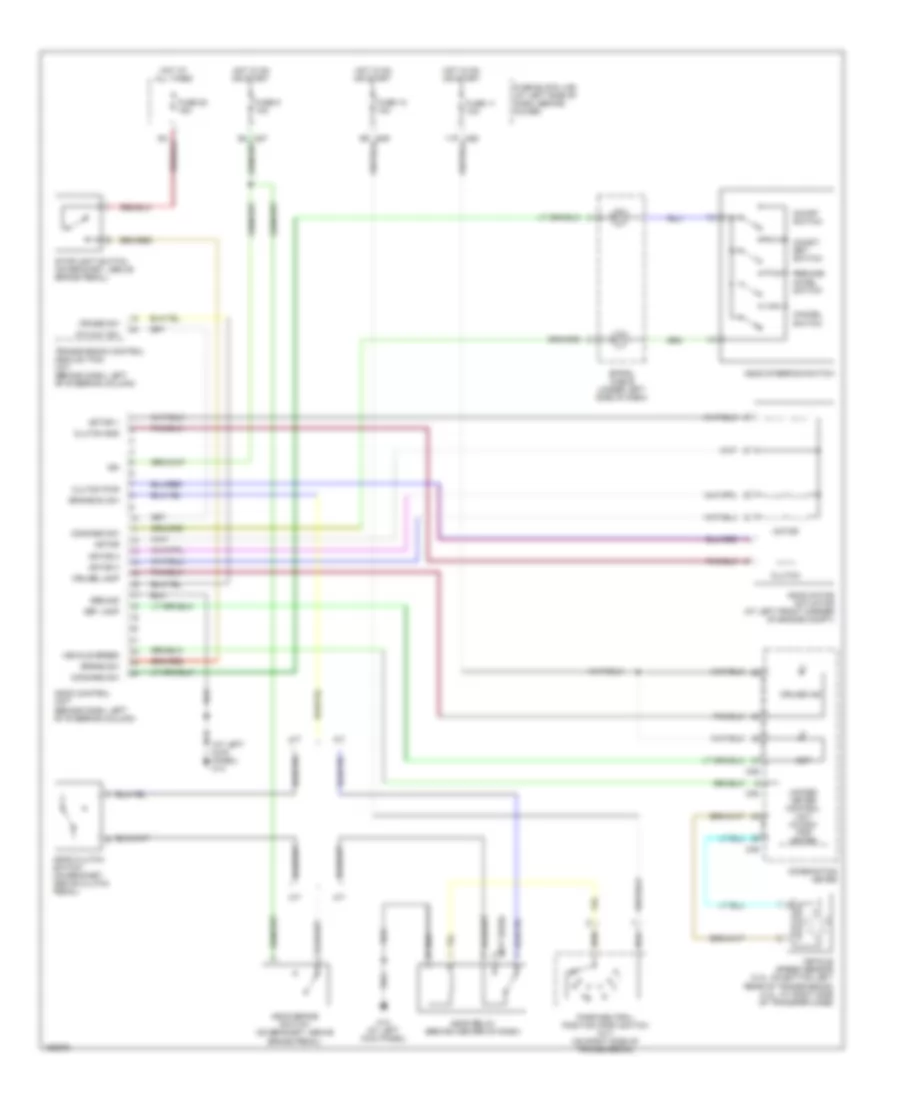
AIR CONDITIONING
Manual A/C Wiring Diagram for Nissan Xterra XE 2004
 https://portal-diagnostov.com/license.html
Automotive Electricians Portal FZCO
Automotive Electricians Portal FZCO
https://portal-diagnostov.com/license.html
https://portal-diagnostov.com/license.html
Automotive Electricians Portal FZCO
Automotive Electricians Portal FZCO
List of elements for Manual A/C Wiring Diagram for Nissan Xterra XE 2004:
- (at left kick panel)
- 10n
- 10p
- 2.4l
- 3.3l
- A/c compressor (2.4l: at left front of engine compartment) (3.3l: at left front of engine)
- Acrly
- Air con
- Air conditioner relay (in relay box)
- Air control
- Amp
- Blower motor (behind glove box, on intake unit)
- Diode 5 (behind center side of dash)
- Ecm (below center of dash, behind lower cover)
- Engine coolant temperature sensor (3.3l: on top front of engine, in water outlet) (2.4l: on right front of engine)
- F12 (2.4l: near engine coolant temperature sensor) (3.3l: on top of intake manifold)
- Fan resistor (behind glove box, near blower motor)
- Fan sw
- Fan switch
- Fresh
- Fuse & fusible link box (at right side of engine compartment)
- Fuse 15a
- Fuse 20a
- Fuse 7.5a
- Fuse block (j/b) (at left side of dash, behind cover)
- Gnd
- Gnd-a
- Hot at all times
- Hot in on
- Hot in on or start
- Iacv-ficd solenoid valve (2.4l: on right side of engine, forward of throttle body) (3.3l: on top rear of engine)
- Iacv-ficd solenoid valve (on top rear of engine)
- Ign sw
- Ill (+)
- Ill (-)
- Intake door motor (behind right side of dash, on intake unit)
- Intake sensor (behind right side of dash)
- Interior lights system
- M14
- M14 (at left kick panel)
- M26
- M27
- M68 (at right kick panel)
- Off
- Pnk
- Rec
- Refrigerant pressure sensor
- Tasw
- Thermal protector
ANTI-LOCK BRAKES
2.4L
2.4L, Anti-lock Brakes Wiring Diagram, 2WD for Nissan Xterra XE 2004
List of elements for 2.4L, Anti-lock Brakes Wiring Diagram, 2WD for Nissan Xterra XE 2004:
- (3.3l) (2.4l)
- 11p
- Abs actuator
- Abs actuator & electric unit (at left rear corner of engine compt)
- Abs control unit
- Abs ind
- Abs lamp
- Combination meter
- Data link connector (under left side of dash, near fuse box cover)
- E12 (near air cleaner)
- E14 (near air cleaner)
- E49
- Fl in
- Fl out
- Fl ss (gnd)
- Fl ss (pwr)
- Fr in
- Fr out
- Fr ss (gnd)
- Fr ss (pwr)
- Fuse & fusible link box (at right side of engine compt)
- Fuse 10a
- Fuse 20a
- Fuse block (j/b) (at left side of dash, behind cover)
- Fusible link c 30a 40a
- Fusible link d 40a
- Hot at all times
- Hot in on or start
- Ign
- Left front wheel sensor (at right front steering knuckle assembly)
- M14 (at left kick panel)
- M26
- M27
- M38
- M39
- Motor monitor
- Motor relay
- Mtr rly
- Pnk
- Pressure switch
- Pressure switch (at left rear corner of engine compartment)
- R ss (gnd)
- R ss (pwr)
- Rear in
- Rear out
- Rear wheel sensor (on rear axle gear carrier)
- Red
- Relay unit
- Right front wheel sensor (at right front steering knuckle assembly)
- Sol rly
- Solenoid valve relay
- Stop
- Stoplight switch (on bracket above brake pedal)
- Txd
- W/l flash
3.3L
3.3L, Anti-lock Brakes Wiring Diagram, 2WD for Nissan Xterra XE 2004
List of elements for 3.3L, Anti-lock Brakes Wiring Diagram, 2WD for Nissan Xterra XE 2004:
- (3.3l) (2.4l)
- 11p
- Abs actuator
- Abs actuator & electric unit (at left rear corner of engine compt)
- Abs control unit
- Abs ind
- Abs lamp
- Combination meter
- Data link connector (under left side of dash, near fuse box cover)
- E12 (near air cleaner)
- E14 (near air cleaner)
- E49
- Fl in
- Fl out
- Fl ss (gnd)
- Fl ss (pwr)
- Fr in
- Fr out
- Fr ss (gnd)
- Fr ss (pwr)
- Fuse & fusible link box (at right side of engine compt)
- Fuse 10a
- Fuse 20a
- Fuse block (j/b) (at left side of dash, behind cover)
- Fusible link c 30a 40a
- Fusible link d 40a
- Hot at all times
- Hot in on or start
- Ign
- Left front wheel sensor (at right front steering knuckle assembly)
- M14 (at left kick panel)
- M26
- M27
- M38
- M39
- Motor monitor
- Motor relay
- Mtr rly
- Pnk
- Pressure switch
- Pressure switch (at left rear corner of engine compartment)
- R ss (gnd)
- R ss (pwr)
- Rear in
- Rear out
- Rear wheel sensor (on rear axle gear carrier)
- Red
- Relay unit
- Right front wheel sensor (at right front steering knuckle assembly)
- Sol rly
- Solenoid valve relay
- Stop
- Stoplight switch (on bracket above brake pedal)
- Txd
- W/l flash
3.3L, Anti-lock Brakes Wiring Diagram, 4WD without Dynamic Stability Control for Nissan Xterra XE 2004
List of elements for 3.3L, Anti-lock Brakes Wiring Diagram, 4WD without Dynamic Stability Control for Nissan Xterra XE 2004:
- (under left side of dash, near fuse box cover)
- 11p
- Abs actuator
- Abs actuator & electric unit (at left rear of engine compt)
- Abs control unit
- Abs ind
- Abs lamp
- Combination meter
- Data link connector
- E12 (near air cleaner)
- E14 (near air cleaner)
- E49
- Fl in
- Fl out
- Fl ss (gnd)
- Fl ss (pwr)
- Fr in
- Fr out
- Fr ss (gnd)
- Fr ss (pwr)
- Fuse & fusible link box (at right side of engine compt)
- Fuse 10a
- Fuse 20a
- Fuse block (j/b) (at left side of dash, behind cover)
- Fusible link c 30a
- Fusible link d 40a
- Hot at all times
- Hot in on or start
- Ign
- Left front wheel sensor (at left front steering knuckle assembly)
- Left rear wheel sensor (on rear axle gear carrier)
- M14 (at left kick panel)
- M26
- M27
- M38
- M39
- Motor monitor
- Motor relay
- Mtr rly
- Pnk
- Rear in
- Rear out
- Red
- Relay unit
- Right front wheel sensor (at right front steering knuckle assembly)
- Right rear wheel sensor (on rear axle gear carrier)
- Rl ss (gnd)
- Rl ss (pwr)
- Rr ss (gnd)
- Rr ss (pwr)
- Sol rly
- Solenoid valve relay
- Stop
- Stoplight switch (on bracket, above brake pedal)
- Txd
- W/l flash
3.3L, Anti-lock Brakes Wiring Diagram, with Dynamic Stability Control (1 of 2) for Nissan Xterra XE 2004
List of elements for 3.3L, Anti-lock Brakes Wiring Diagram, with Dynamic Stability Control (1 of 2) for Nissan Xterra XE 2004:
- (under left side of dash, near fuse box cover)
- 11p
- 4wd sw
- Abs actuator
- Abs actuator & electric unit (at left rear of engine compt)
- Abs control unit
- Abs lamp
- Can-h
- Can-l
- Can2-h
- Can2-l
- Data link connector
- Dr1 gnd
- Dr1 sense
- Dr1 sig
- E12 (near air cleaner)
- E14 (near air cleaner)
- E49
- Fl in
- Fl out
- Fl ss (gnd)
- Fl ss (pwr)
- Fr in
- Fr out
- Fr ss (gnd)
- Fr ss (pwr)
- Fuse & fusible link box (at right side of engine compt)
- Fuse 10a
- Fuse 20a
- Fuse block (j/b) (at left side of dash, behind cover)
- Fusible link c 30a
- Fusible link d 40a
- Gs gnd
- Gs sig
- Hot at all times
- Hot in on or start
- Ign
- Interior lights system
- L/s
- Left front wheel sensor (at left front steering knuckle assembly)
- Left rear wheel sensor (on rear axle gear carrier)
- M14 (at left kick panel)
- M26
- M27
- Motor monitor
- Motor relay
- Mtr rly
- Pnk
- Rear in
- Rear out
- Red
- Relay unit
- Right front wheel sensor (at right front steering knuckle assembly)
- Right rear wheel sensor (on rear axle gear carrier)
- Rl ss (gnd)
- Rl ss (pwr)
- Rr ss (gnd)
- Rr ss (pwr)
- Sol rly
- Solenoid valve relay
- Stop
- Stoplight switch (on bracket, above brake pedal)
- Tcs slip
- Txd
- Vdc off
- Vdc off sw
- Vdc off switch
- W/l flash
3.3L, Anti-lock Brakes Wiring Diagram, with Dynamic Stability Control (2 of 2) for Nissan Xterra XE 2004
List of elements for 3.3L, Anti-lock Brakes Wiring Diagram, with Dynamic Stability Control (2 of 2) for Nissan Xterra XE 2004:
- 4wd
- Abs ind
- Ascd control unit (behind dash, left of steering column)
- Brake
- Brake fluid level switch (in brake fluid reservoir)
- Can-h
- Can-l
- Can-lan converter (clc) (behind left side of dash)
- Combination meter
- Diode 1 (behind left side of dash)
- Diode 3 (behind right side of dash)
- E12 (near air cleaner)
- Ecm (below center of dash, behind lower cover)
- F29
- Gnd
- Ign
- Lan-8
- M119
- M14 (at left kick panel)
- M38
- M39
- M68 (at right kick panel)
- M78
- Of dash, near steering column)
- Parking brake switch (on base of parking brake lever)
- Power
- Pressure sensor
- Reverse
- Sensor (below left side
- Slip ind
- Steering angle
- Tach
- Transmission control module (tcm) (behind dash, left of steering column)
- Transmissions system
- Vdc off ind
- Yaw rate/g sensor (under rear of center console)
ANTI-THEFT
Anti-theft Wiring Diagram for Nissan Xterra XE 2004
List of elements for Anti-theft Wiring Diagram for Nissan Xterra XE 2004:
- 1p m26
- 6n m27
- 9n m27
- Acc sw
- B6 (near left rear seat)
- Back door key cylinder switch (at lower right center of back door)
- Back door switch open (at lower left center of back door)
- Bat (fuse)
- D402 (at left rear corner of vehicle)
- Door lk out (all)
- Door locks system
- Door sw (as)
- Door sw (dr)
- Door switch (rear)
- Door unlk out (dr)
- E12 (near air cleaner)
- E54 (at right rear corner of engine compt)
- Fuse & fusible link box (at right side of engine compt)
- Fuse 10a
- Fuse 15a
- Fuse 7.5a
- Fuse block (j/b) (at left side of dash, behind cover)
- Ground
- Headlamps output
- Headlights system
- Hood sw
- Hood switch (3.3l: at left front of engine compt, near air intake box)
- Horn (at center front of engine compt)
- Horn output
- Horn relay (in relay box)
- Horns system
- Hot at all times
- Hot in on or acc
- Hot in on or start
- Ign sw
- Inserted
- Key cyl sw (lock)
- Key cyl sw (unlk)
- Key sw
- Key switch
- Left front door key cylinder switch
- Left front door open switch (at base of left "b" pillar)
- Left rear door switch (at left "c" pillar)
- M110
- M111
- M112
- M14 (at left kick panel)
- Mid stroke
- Red
- Removed
- Right front door open switch (at right "b" pillar)
- Right rear door switch (at right "c" pillar)
- Security ind output
- Security indicator lamp
- Smart entrance control unit (behind dash, right of steering column)
- Starter cut
- Starting/ charging system
- Unlk
- Unlk out (as/rr)
- Vehicle security lamp relay (in relay box)
- Vehicle security relay
BODY CONTROL MODULES
Body Control Modules Wiring Diagram for Nissan Xterra XE 2004
List of elements for Body Control Modules Wiring Diagram for Nissan Xterra XE 2004:
- Anti-theft system
- Battery saver
- Circuit breaker (behind lower left end of dash)
- Defogger system
- Door locks system
- Door sws
- Dr lk actuators
- Dr lk sw
- Dr unlk sw
- Exterior lights system
- Fuse & fusible link box (at right side of engine compt)
- Fuse 10a
- Fuse 7.5a
- Fuse block (j/b) (at left side of dash, behind cover)
- Fusible link f 30a
- Gnd 1
- Gnd 2
- Hood sw
- Horn rly
- Hot at all times
- Hot in acc or on
- Hot in on or start
- Ign (acc)
- Ign (on)
- Ign key sw
- Interior lights system
- Key switch
- Lf ft key cyl sw
- Lighting sw
- Lt ft dr sw
- Lt ft key cyl sw
- Lt trun sig lamp
- M110
- M111
- M112
- M14 (at left kick panel)
- M26
- M27
- Power windows system
- Pwr
- Pwr window rly
- Rear dr sws
- Red
- Room lamp
- Rr defog rly
- Rr defog sw
- Rt ft dr sw
- Rt turn sig lamp
- Seat belt sw
- Sec ind
- Security indicator lamp
- Smart entrance control unit (behind dash, right of steering column)
- Veh sec lamp rly
- Veh sec rly
- Warning system
COMPUTER DATA LINES
Computer Data Lines Wiring Diagram for Nissan Xterra XE 2004
List of elements for Computer Data Lines Wiring Diagram for Nissan Xterra XE 2004:
- Abs actuator & electric unit (at left rear corner of engine compt)
- Air bag diagnosis sensor unit (under console box)
- Data link connector (under left side of dash, near fuse box cover)
- Ecm (below center of dash, behind lower cover)
- F11 (3.3l: on top of intake manifold, 2.4l: near engine coolant temperature sensor)
- Fuse 11 10a
- Fuse 26 7.5a
- Fuse block (j/b) (at left side of dash, behind cover)
- Hot at all times
- Hot in on or start
- K-line
- Kline
- Low tire pressure warning control unit (behind dash, right of steering column)
- M14 (at left kick panel)
- M26
- M27
- M78
- Sss rx
- Sss tx
- Transmission control module (tcm) (behind dash, left of steering column)
- Txd
- W/l flash
CRUISE CONTROL
Cruise Control Wiring Diagram for Nissan Xterra XE 2004
List of elements for Cruise Control Wiring Diagram for Nissan Xterra XE 2004:
- (at left kick panel) m14
- (not used)
- 4th cut sw
- A/t
- Ascd brake switch (on bracket, above brake pedal)
- Ascd clutch switch (on bracket, above clutch pedal)
- Ascd control unit (behind dash, left of steering column)
- Ascd motor actuator (at left front corner of engine compt)
- Ascd relay (behind center of dash)
- Ascd steering switch
- Brake nc sw
- Brake sw
- Cancel switch
- Clutch
- Clutch gnd
- Clutch pwr
- Coast/ set switch
- Combination meter
- Command sw
- Cruise ind
- Cruise lamp
- Cruise sw
- Fuse 11 10a
- Fuse 12 10a
- Fuse 22 15a
- Fuse 5 10a
- Fuse block (j/b) (at left side of dash, behind cover)
- Ground
- Hot at all times
- Hot in on or start
- Ign
- M/t
- M14 (at left kick panel)
- M38
- M39
- Motor
- Motor 1
- Motor 2
- Motor 3
- On/off switch
- Park/neutral position (pnp) switch (a/t) (on right side of transmission)
- Resume/ accel switch
- Set
- Set lamp
- Spiral cable (under left side of dash)
- Stoplight switch (on bracket, above brake pedal)
- Transmission control module (tcm) (a/t) (behind dash, left of steering column)
- Unified meter control unit (w/odo/ trip meter)
- Vehicle speed
- Vehicle speed sensor (2.4l: on bottom left rear of transmission) (3.3l: at right side of transfer case)
DEFOGGERS
Defoggers Wiring Diagram for Nissan Xterra XE 2004
List of elements for Defoggers Wiring Diagram for Nissan Xterra XE 2004:
- (at left rear corner of vehicle)
- (frontier) (xterra)
- (frontier: right "a" pillar) m68 (xterra: at right kick panel)
- (xterra) (frontier)
- 1q m31
- Air control (rear window defogger switch)
- D402
- D507 r101
- Frontier
- Fuse 20a
- Fuse 28 7.5a
- Fuse 5 10a
- Fuse block (at left side of dash, behind cover)
- Hot at all times
- Hot in on or start
- Ind
- M110
- M111
- M112
- M14 (frontier: left "a" pillar) (xterra: at left kick panel)
- M27
- R102
- R8 d502
- Rear window defogger
- Rear window defogger relay (behind left side of dash)
- Rear window defogger switch
- Rear window defogger timer (frontier: left side of dash, right of steering column) (xterra: behind left side of dash)
- Smart entrance control unit (behind dash, right of steering column)
- W/ power door locks
- W/o power door locks
- Xterra
- Xterra, w/ power door locks
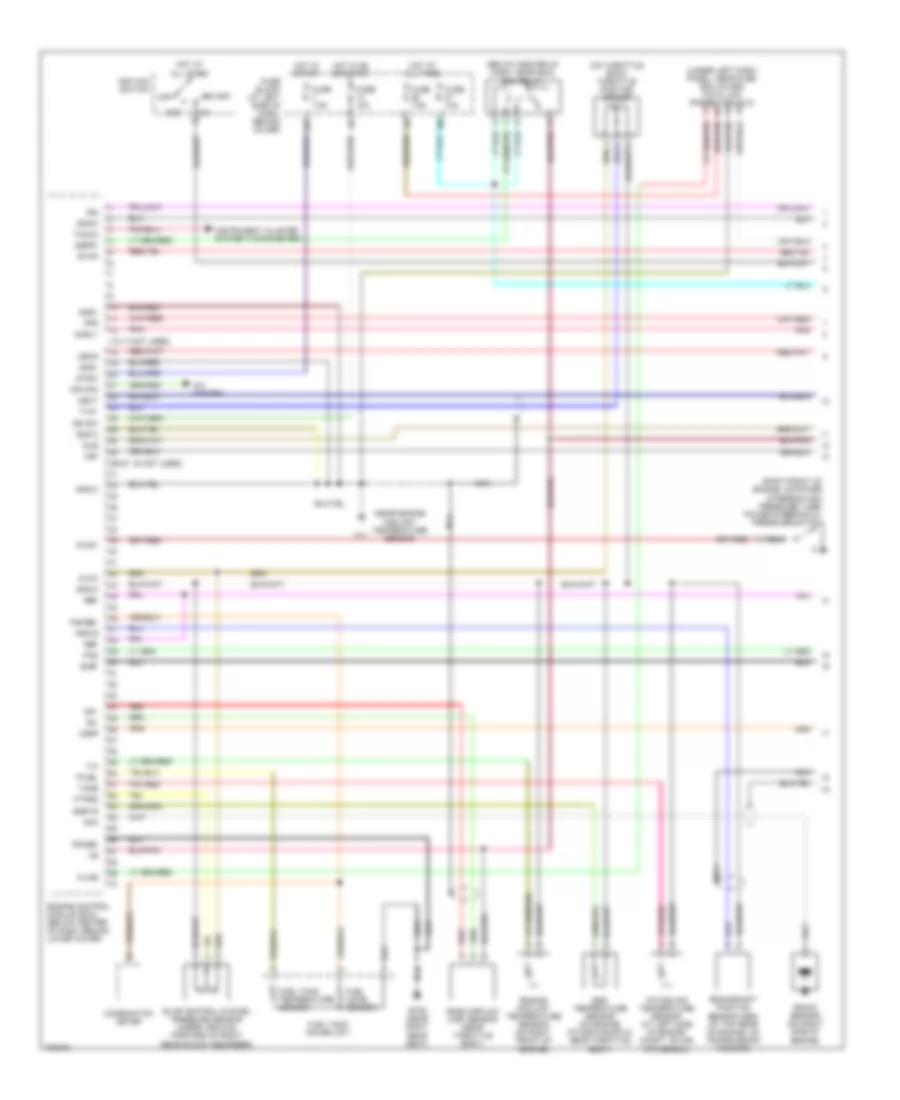
ENGINE PERFORMANCE
2.4L
2.4L, Engine Performance Wiring Diagram (1 of 3) for Nissan Xterra XE 2004
List of elements for 2.4L, Engine Performance Wiring Diagram (1 of 3) for Nissan Xterra XE 2004:
- (13-17 not used)
- (26-27, 30 not used)
- (below center of dash, near ecm) ecm relay
- (near engine coolant temperature sensor)
- (on throttle body) throttle position sensor
- (right front of engine, on power steering high pressure tube) power steering oil pressure switch
- (under left dash panel, near fuse box cover) data link connector (dlc)
- 13p
- A/c system
- Acc
- Acrly
- Air con
- Avcc
- B106 (near right rear seat)
- Combination meter
- Crankshaft position sensor (obd) (at top rear of engine, on transmission housing)
- Egr temperature sensor (on engine intake manifold, near throttle body)
- Egrts
- Engine control module (ecm) (below center of dash, behind lower cover)
- Engine coolant temperature sensor (on right front of engine)
- Evap
- Evap control system pressure sensor (under vehicle, forward of right rear shock absorber)
- F11
- Fgage+
- Fgage-
- Fpr
- Ftprs
- Fuel level sensor
- Fuel tank gauge unit
- Fuel tank temperature sensor
- Fuse 10a
- Fuse 7.5a
- Fuse block (at left side of dash, behind cover)
- Gnd-a
- Gnd-c
- Gnd-i
- Hot at all times
- Hot in on or start
- Hot in start
- Idle
- Ign
- Ign sw
- Ignck
- Ignition switch
- Instrument cluster system (tachometer)
- Intake air temperature sensor (at left side of engine compt, on air intake box)
- Kline
- Knk
- Knock sensor (on right side of engine)
- Led-r
- Mass airflow (maf) sensor (near throttle body)
- Nca
- Neut
- O2sf
- O2sr
- Off
- Pnk
- Pos
- Pwst
- Qa+
- Qa-
- Red
- Ref
- Rgc/s
- Ssoff
- Start
- Stsw
- Tacho
- Tamb
- Tfuel
- Tvo1
- Vsp
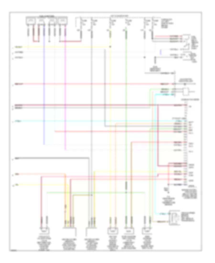
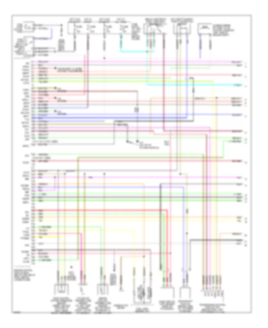
2.4L, Engine Performance Wiring Diagram (2 of 3) for Nissan Xterra XE 2004
List of elements for 2.4L, Engine Performance Wiring Diagram (2 of 3) for Nissan Xterra XE 2004:
- (in relay box) a/c relay
- (not used)
- (on throttle body) throttle position switch
- A/c system
- Camshaft position sensor
- Condenser
- Distributor
- E54 (at right rear corner of engine compt)
- Evap canister purge volume control solenoid valve (on right side of engine compt, near power steering oil reservoir)
- F11 (near engine coolant temp- erature sensor)
- F12 (near engine coolant temperature sensor)
- Fuse & fusible link box (at right side of engine compt)
- Fuse 7.5a
- Hot at all times
- Hot in on
- Iacv-ficd solenoid valve (on right side of engine, forward of throttle body)
- Ignition coil
- Nca
- P/n
- Park/ neutral position (pnp) switch (on right side of transmission)
- Pnk
- Power transistor
- Resistor (at left front side of engine, near distributor)
- Tp sw
- Wotp sw
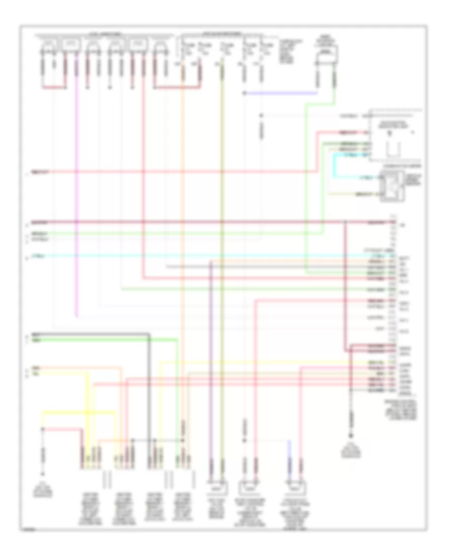
2.4L, Engine Performance Wiring Diagram (3 of 3) for Nissan Xterra XE 2004
List of elements for 2.4L, Engine Performance Wiring Diagram (3 of 3) for Nissan Xterra XE 2004:
- (77-79 not used)
- 1o1
- B106 (near right rear seat)
- Batt
- Cdcv
- Combination meter
- Coolant temperature sensor)
- Crtn
- Cvbv
- Egr
- Egrc solenoid valve (on right side of engine, near egr valve)
- Engine control module (ecm) (below center of dash, behind lower cover)
- Evap canister vent control valve (under right rear of vehicle, on evap canister)
- F12 (near engine
- Fuel injectors
- Fuel pump (in fuel tank)
- Fuel pump relay (behind left side of dash)
- Fuse 10a
- Fuse 15a
- Fuse block (at left side of dash, behind cover)
- Gnd-e
- Heated oxygen sensor 1 (at left side of engine, on exhaust manifold)
- Heated oxygen sensor 2 (on exhaust pipe, forward of catalytic converter)
- Hot in on or start
- Iacv-aac valve (on right side of engine, forward of throttle body)
- Inj 1
- Inj 2
- Inj 3
- Inj 4
- Isc
- Malfunction indicator lamp
- O2hf
- O2hr
- Vacuum cut valve by-pass valve (between fuel tank & evap canister, on evap purge line)
- Vehicle speed sensor (bottom left rear of transmission)
3.3L
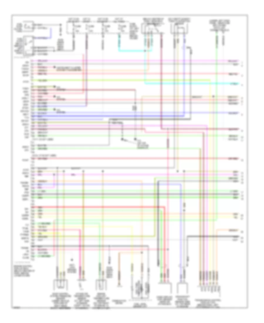
3.3L, Engine Performance Wiring Diagram (1 of 3) for Nissan Xterra XE 2004
List of elements for 3.3L, Engine Performance Wiring Diagram (1 of 3) for Nissan Xterra XE 2004:
- (13-17, 30 not used)
- (33-34, 37-38 not used)
- (below center of dash, near ecm) ecm relay
- (on throttle body) throttle position sensor
- (under left dash panel, near fuse box cover) data link connector (dlc)
- 13p
- A/c system
- Acrly
- Air con
- Anti- lock brakes system
- Atck
- Avcc
- B106 (near right rear seat)
- Combination meter
- Crankshaft position sensor (obd) (at top rear of engine)
- Dt1
- Dt2
- Dt3
- Egrts
- Engine control module (ecm) (below center of dash, behind lower cover)
- Engine coolant temperature sensor (on top front of engine, in water outlet)
- Evap
- Evap control system pressure sensor (under vehicle, forward of right rear shock absorber)
- F11
- F12 (on top of intake manifold)
- Fgage+
- Fgage-
- Fpr
- Ftpres
- Fuel level sensor
- Fuel level sensor unit
- Fuel pump (in fuel tank)
- Fuel pump relay (behind left side of dash)
- Fuel tank temperature sensor
- Full
- Fuse 10a
- Fuse 15a
- Fuse 7.5a
- Fuse block (at left side of dash, behind cover)
- Gnd-a
- Gnd-c
- Gnd-i
- Hot at all times
- Hot in on or start
- Hot in start
- Idle
- Ign
- Ign sw
- Ignck
- Instrument cluster system (tachometer)
- Intake air temperature sensor (at left side of engine compt, on air intake box)
- Kline
- Knk
- Lan-8
- Led-r
- Mass airflow (maf) sensor (near air intake box)
- Nca
- Neut
- O2sfl
- O2sfr
- O2srl
- O2srr
- Obd2
- Pnk
- Pos
- Pwst
- Qa+
- Qa-
- Red
- Ref
- Rgc/s
- Ssoff
- Stsw
- Tacho
- Tamb
- Tasw
- Tfuel
- Transmission control module (tcm) (behind dash, left of steering column)
- Tvo
- Vsp
3.3L, Engine Performance Wiring Diagram (2 of 3) for Nissan Xterra XE 2004
List of elements for 3.3L, Engine Performance Wiring Diagram (2 of 3) for Nissan Xterra XE 2004:
- (in relay box) park/neutral position relay
- (on engine intake manifold, near throttle body) egr temp- erature sensor
- (on right side of transmission) park/neutral position switch
- (on throttle body) throttle position switch
- A/t
- Acc
- Camshaft position sensor
- Condenser
- Ctp sw
- Distributor
- E12 (near air cleaner)
- Evap canister purge volume control solenoid valve (on left side of engine compt, outboard of brake fluid reservoir)
- F11 (on top of intake manifold)
- F12 (on top
- Fuse 7.5a
- Fuse block (at left side of dash, behind cover)
- Hot at all times
- Hot in on or start
- Ignition coil
- Ignition switch
- Knock sensor (on top rear of engine)
- M/t
- Nca
- Of intake manifold)
- Off
- P/n
- Park/ neutral position (pnp) switch (on right side of trans)
- Power steering oil pressure switch (near right front side of engine)
- Power transistor
- Resistor (on top right side of engine, next to distributor)
- Start
- Starting/ charging system
- W/ security
- W/o security
- Wotp sw
3.3L, Engine Performance Wiring Diagram (3 of 3) for Nissan Xterra XE 2004
List of elements for 3.3L, Engine Performance Wiring Diagram (3 of 3) for Nissan Xterra XE 2004:
- (77-79 not used)
- 1o1
- Batt
- Cdcv
- Combination meter
- Crtn
- Cvbv
- Egr
- Egrc solenoid valve
- Engine control module (ecm) (below center of dash, behind lower cover)
- Evap canister vent control valve (under right rear of vehicle, on evap canister)
- F11 (on top of intake manifold)
- F12 (on top of intake manifold)
- Fuel injectors
- Fuse 10a
- Fuse 15a
- Fuse block (at left side of dash, behind cover)
- Gnd-e
- Heated oxygen sensor 1 (bank 1) (on inlet of right catalyst)
- Heated oxygen sensor 1 (bank 2) (on inlet of left catalyst)
- Heated oxygen sensor 2 (bank 1) (on inlet of right three way converter)
- Heated oxygen sensor 2 (bank 2) (on inlet of left three way converter)
- Hot in on or start
- Iacv-aac valve (on top rear of engine)
- Inj 1
- Inj 2
- Inj 3
- Inj 4
- Inj 5
- Inj 6
- Isc
- Malfunction indicator lamp
- O2hfl
- O2hfr
- O2hrl
- O2hrr
- Vacuum cut valve by-pass valve (between fuel tank & evap canister, on evap purge line)
- Vehicle speed sensor
3.3L SC
3.3L SC, Engine Performance Wiring Diagram (1 of 3) for Nissan Xterra XE 2004
List of elements for 3.3L SC, Engine Performance Wiring Diagram (1 of 3) for Nissan Xterra XE 2004:
- (13-17, 30, 31 not used)
- (33-38 not used)
- (below center of dash, near ecm) ecm relay
- (on throttle body) throttle position sensor
- 13p
- A/c system
- Acrly
- Air con
- Anti- lock brakes system
- Atck
- Avcc
- B106 (near right rear seat)
- Combination meter
- Crankshaft position sensor (obd) (at top rear of engine)
- Dt1
- Dt2
- Dt3
- Engine control module (ecm) (below center of dash, behind lower cover)
- Engine coolant temperature sensor (on top front of engine, in water outlet)
- Evap
- Evap control system pressure sensor (under vehicle, forward of right rear shock absorber)
- F11
- F12 (on top of intake manifold)
- Fgage+
- Fgage-
- Fpr
- Ftpres
- Fuel level sensor
- Fuel level sensor unit
- Fuel pump (in fuel tank)
- Fuel pump relay (behind left side of dash)
- Fuel tank temperature sensor
- Full
- Fuse 10a
- Fuse 15a
- Fuse 7.5a
- Fuse block (at left side of dash, behind cover)
- Gnd-a
- Gnd-c
- Gnd-i
- Hot at all times
- Hot in on or start
- Hot in start
- Idle
- Ign
- Ign sw
- Ignck
- Instrument cluster system (tachometer)
- Intake air temperature sensor (at left side of engine compt, on air intake box)
- Kline
- Knk
- Lan-8
- Led-r
- Mass airflow (maf) sensor (near air intake box)
- Nca
- Neut
- O2sfl
- O2sfr
- O2srl
- O2srr
- Obd2
- Pnk
- Pos
- Pwst
- Qa+
- Qa-
- Red
- Ref
- Rgc/s
- S/c sol
- Ssoff
- Stsw
- Supercharger by-pass valve control solenoid (left side of engine compt)
- Tacho
- Tamb
- Tasw
- Tfuel
- Transmission control module (tcm) (behind dash, left of steering column)
- Tvo
- Vsp
3.3L SC, Engine Performance Wiring Diagram (2 of 3) for Nissan Xterra XE 2004
List of elements for 3.3L SC, Engine Performance Wiring Diagram (2 of 3) for Nissan Xterra XE 2004:
- (in relay box) park/neutral position relay
- (on right side of transmission) park/neutral position switch
- (on throttle body) throttle position switch
- A/t
- Acc
- Camshaft position sensor
- Condenser
- Ctp sw
- Distributor
- E12 (near air cleaner)
- Evap canister purge volume control solenoid valve (on left side of engine compt, outboard of brake fluid reservoir)
- F11 (on top of intake manifold)
- F12 (on top of intake manifold)
- Fuse 7.5a
- Fuse block (at left side of dash, behind cover)
- Hot at all times
- Hot in on or start
- Ignition coil
- Ignition switch
- Knock sensor (on top rear of engine)
- M/t
- Nca
- Off
- P/n
- Park/ neutral position (pnp) switch (on right side of trans)
- Power steering oil pressure switch (near right front side of engine)
- Power transistor
- Resistor (on top right side of engine, next to distributor)
- Start
- Starting/ charging system
- W/ security
- W/o security
- Wotp sw
3.3L SC, Engine Performance Wiring Diagram (3 of 3) for Nissan Xterra XE 2004
List of elements for 3.3L SC, Engine Performance Wiring Diagram (3 of 3) for Nissan Xterra XE 2004:
- (77-79 not used)
- (under left dash panel, near fuse box cover) data link connector (dlc)
- 1o1
- Batt
- Cdcv
- Combination meter
- Crtn
- Cvbv
- Engine control module (ecm) (below center of dash, behind lower cover)
- Evap canister vent control valve (under right rear of vehicle, on evap canister)
- F11 (on top of intake manifold)
- F12 (on top of intake manifold)
- Fuel injectors
- Fuse 10a
- Fuse 15a
- Fuse block (at left side of dash, behind cover)
- Gnd-e
- Heated oxygen sensor 1 (bank 1) (on inlet of right catalyst)
- Heated oxygen sensor 1 (bank 2) (on inlet of left catalyst)
- Heated oxygen sensor 2 (bank 1) (on inlet of right three way converter)
- Heated oxygen sensor 2 (bank 2) (on inlet of left three way converter)
- Hot in on or start
- Iacv-aac valve (on top rear of engine)
- Inj 1
- Inj 2
- Inj 3
- Inj 4
- Inj 5
- Inj 6
- Isc
- Malfunction indicator lamp
- O2hfl
- O2hfr
- O2hrl
- O2hrr
- Vacuum cut valve by-pass valve (between fuel tank & evap canister, on evap purge line)
- Vehicle speed sensor
EXTERIOR LIGHTS
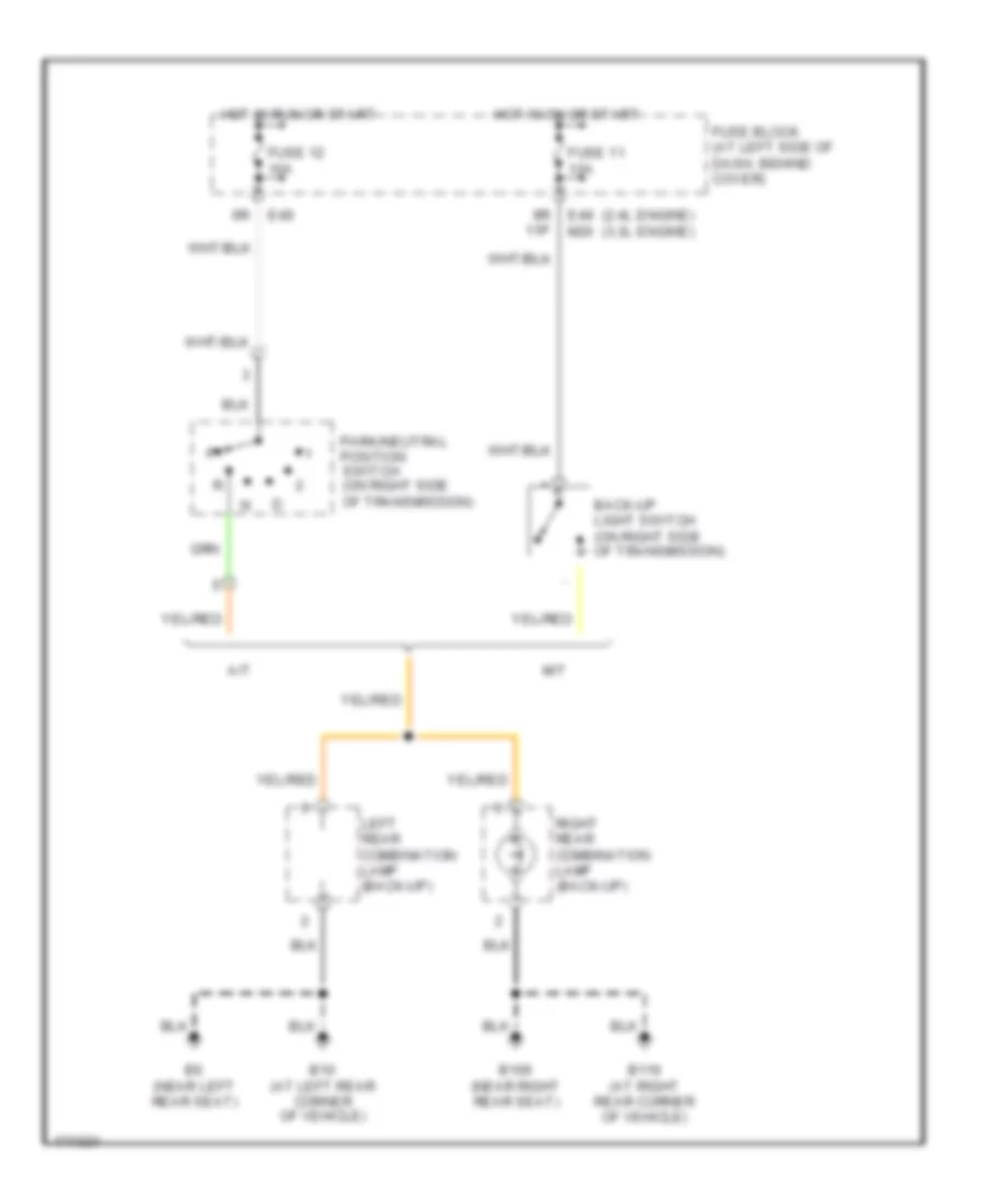
Back-up Lamps Wiring Diagram for Nissan Xterra XE 2004
List of elements for Back-up Lamps Wiring Diagram for Nissan Xterra XE 2004:
- (2.4l engine) (3.3l engine)
- 9r 11p
- A/t
- B10 (at left rear corner of vehicle)
- B106 (near right rear seat)
- B116 (at right rear corner of vehicle)
- B6 (near left rear seat)
- Back-up light switch (on right side of transmission)
- E49
- E49 m26
- Fuse 11 10a
- Fuse 12 10a
- Fuse block (at left side of dash, behind cover)
- Hot in on or start
- Hot in run or start
- Left rear combination lamp (back-up)
- M/t
- Park/neutral position switch (on right side of transmission)
- Right rear combination lamp (back-up)
Exterior Lamps Wiring Diagram for Nissan Xterra XE 2004
List of elements for Exterior Lamps Wiring Diagram for Nissan Xterra XE 2004:
- 1st
- 2nd
- B10 (at left rear corner of vehicle)
- B106 (near right rear seat)
- B116 (at right rear corner of vehicle)
- B6 (near left rear seat)
- Combination flasher unit (behind center of dash)
- Combination meter
- Combination switch (lighting switch)
- Combination switch (turn signal switch)
- D402 (at left rear corner of vehicle)
- D404 (at left rear corner of vehicle)
- D507
- E12 (near air cleaner)
- E54 (at right rear corner of engine compartment)
- Fuse & fusible link box (at right side of engine compartment)
- Fuse 17 10a
- Fuse 2 7.5a
- Fuse 22 20a
- Fuse 39 15a
- Fuse block (j/b) (at left side of dash, behind cover)
- Ground
- Hazard
- Hazard switch
- High mounted stop
- Hot at all times
- Hot in on or start
- Interior lights system
- Lamp
- Left front combination lamp
- Left license plate lamp
- Left rear combination lamp
- Left side marker lamp
- Left turn ind
- M111
- M14 (at left kick panel)
- M26
- M27
- M68 (at right kick panel)
- Off
- Out
- Power
- Rear window defogger
- Right front combination lamp
- Right license plate lamp
- Right rear combination lamp
- Right side marker lamp
- Right turn ind
- Smart entrance control unit (behind dash, right of steering column)
- Stop
- Stoplight switch (on bracket, above brake pedal)
- Tail
- Trailer tow circuit
- Trailer tow control unit (at right rear corner of vehicle)
- Turn
- W/ low tire pressure monitoring system
- W/ power door locks
- Warning system
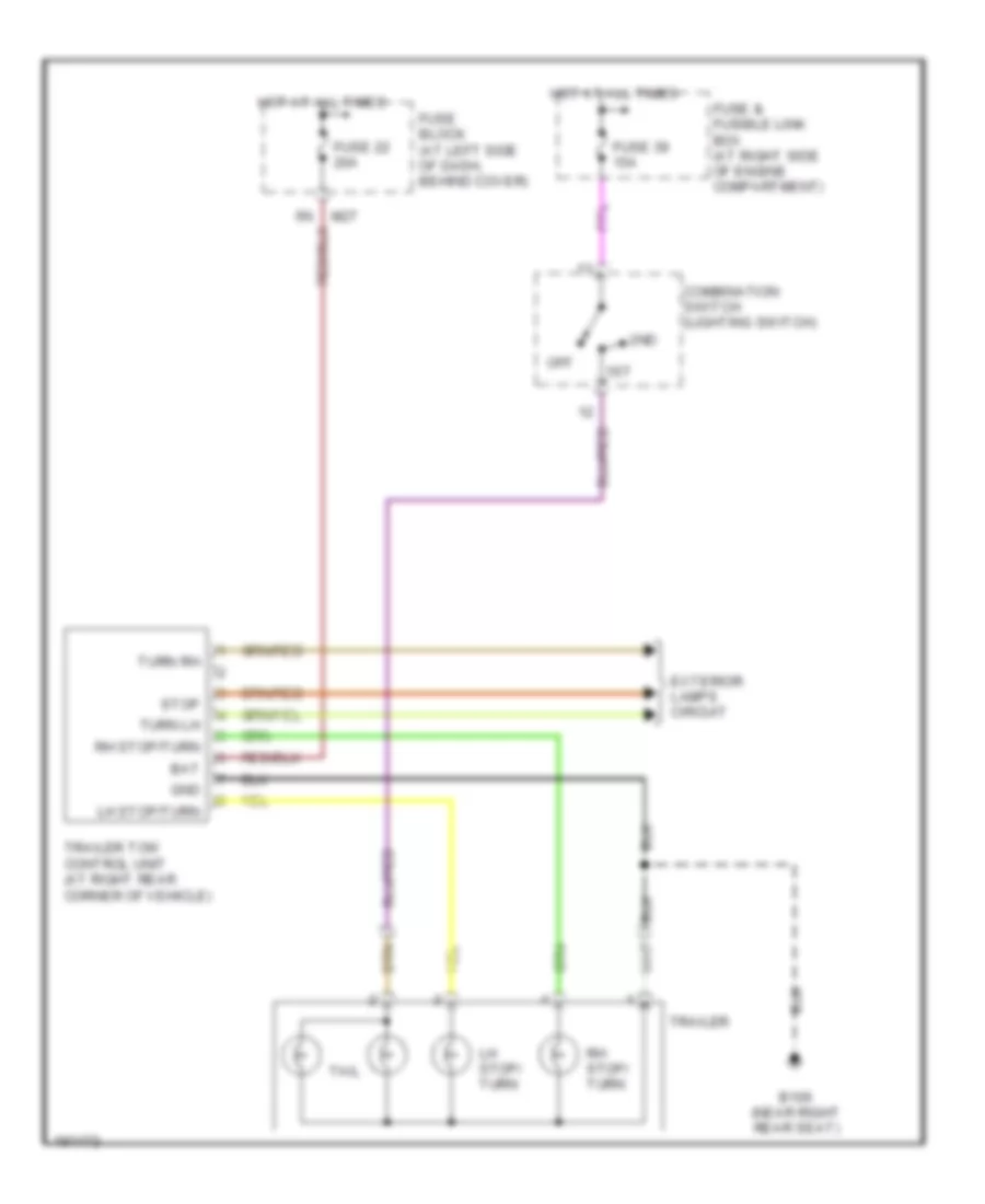
Trailer Tow Wiring Diagram for Nissan Xterra XE 2004
List of elements for Trailer Tow Wiring Diagram for Nissan Xterra XE 2004:
- 1st
- 2nd
- B106 (near right rear seat)
- Bat
- Combination switch (lighting switch)
- Exterior lamps circuit
- Fuse & fusible link box (at right side of engine compartment)
- Fuse 22 20a
- Fuse 39 15a
- Fuse block (at left side of dash, behind cover)
- Gnd
- Hot at all times
- Lh stop/ turn
- Lh stop/turn
- M27
- Off
- Rh stop/ turn
- Rh stop/turn
- Stop
- Tail
- Trailer
- Trailer tow control unit (at right rear corner of vehicle)
- Turn lh
- Turn rh
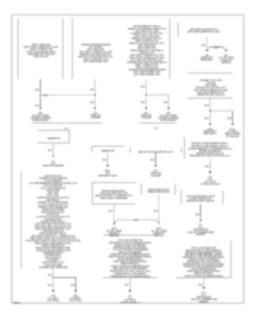
GROUND DISTRIBUTION
Ground Distribution Wiring Diagram for Nissan Xterra XE 2004
List of elements for Ground Distribution Wiring Diagram for Nissan Xterra XE 2004:
- 2.4l
- 3.3l
- A1 (3.3l) (near air cleaner)
- Abs actuator & electric unit.
- Air bag diagnosis sensor unit shield, left headlamp, left front combination lamp, brake fluid level switch, abs actuator & electric unit, front wiper switch & left side maker lamp.
- B10 (at left rear corner of vehicle)
- B106 (near right rear seat)
- B116 (at right rear corner of vehicle)
- B6 (near left rear seat)
- Back door switch, rear wiper motor.
- Crankshaft position sensor shield, camshaft position sensor, engine control module (ecm), a/t fluid temperature sensor revolution sensor camshaft position sensor shield, front heated oxygen sensor shield, knock sensor shield, mass airflow sensor shield, resistor shield, throttle position sensor shield, rear heated oxygen sensor, transmission control module (tcm),
- D402 (at left rear corner of vehicle)
- D404 (at left rear corner of vehicle)
- Data link connector,
- Data link connector, rear heated oxygen sensor 2, heated oxygen sensor 1 shield, heated oxygen sensor 2 shield, crankshaft position sensor shield, camshaft position sensor, engine control module (ecm), engine control module (ecm) shield, camshaft position sensor shield, knock sensor shield, mass airflow sensor shield, resistor shield, throttle position sensor shield.
- E12 (near air cleaner)
- E14 (near air cleaner)
- E203 (2.4l) (near relay box)
- E54 (at right rear corner of engine compartment)
- F11 (2.4l) (near engine coolant temperature sensor)
- F11 (3.3l) (on top of intake manifold)
- F12 (2.4l) (near engine coolant temperature sensor)
- F12 (3.3l) (on top of intake manifold)
- Generator
- Generator.
- Heated oxygen sensor 2 bank 1,
- Heated oxygen sensor 2 bank 2,
- Iacv-ficd solenoid valve, power transistor, engine control module.
- Left front door switch, left rear combination lamp.
- License plate lamp, trailer, fuel pump, trailer tow control unit, right rear combination lamp, fuel level sensor unit, engine control module.
- M14 (at left kick panel)
- M68 (at right kick panel)
- Power steering oil pressure switch, power transistor, engine control module, park/neutral position switch (m/t).
- Rear power socket, high mounted stop lamp, back door key cylinder switch, rear window defogger.
- Right headlamp, right front combination lamp, front wiper motor, right side marker lamp & park/neutral position (pnp) switch.
- Turbine revolution sensor, turbine revolution sensor shield.
- Vdc off switch, steering angle sensor, intake sensor, low tire pressure warning control unit, can converter, data link connector, air control, map lamp, shift lock, over drive control switch, ascd relay, cigarette lighter socket, clutch interlock switch, combination flasher unit, combination meter, door mirror switch, fan switch, illumination control switch, power socket, power window relay, left seat belt buckle switch, right seat belt buckle switch, smart entrance control unit, warning chime unit, vehicle security relay, left front door key cylinder switch, right front door lock & unlock switch, main power window & door lock/unlock switch, rear window defogger switch, rear wiper switch, rear window defogger timer, air bag diagnosis sensor unit accessory relay, blower relay, ignition relay, atp relay, ascd control unit, audio amplifier, compass and thermoter.
- Vehicle security relay, ambient air temperature switch, left front fog lamp, washer fluid level switch, right front fog lamp, brake fluid level switch, front wiper switch, abs actuator & electric unit, left headlamp, right headlamp, vehicle security lamp relay, hood switch, left front combination lamp, right front combination lamp, daytime light control unit, park/neutral position (pnp) relay, front wiper switch, front wiper motor, air bag diagnosis sensor shield right side marker lamp, left side marker lamp.
HEADLIGHTS
Headlights Wiring Diagram, with DRL for Nissan Xterra XE 2004
List of elements for Headlights Wiring Diagram, with DRL for Nissan Xterra XE 2004:
- (at left side of dash, behind cover)
- (at right front corner of engine compt)
- 13p
- 1st
- 2.4l
- 2nd
- 3.3l
- Alt-l
- Anti-theft system
- Combination meter
- Combination switch (front fog lamp switch)
- Combination switch (lighting switch)
- Daytime light control unit
- E12 (near air cleaner)
- E17
- E18
- E207
- E45
- E47
- E49
- E54 (at right rear corner of engine compartment)
- E59
- Front fog lamp relay (in relay box)
- Fuse & fusible link box (at right side of engine compt)
- Fuse 37 15a
- Fuse 38 15a
- Fuse 40 15a
- Fuse 5 10a
- Fuse 7 7.5a
- Fuse block (j/b)
- Generator
- Gnd
- H/l dim sw
- H/l main sw
- Hi beam ind
- High
- Hot at all times
- Hot in on or start
- Hot in start
- Ign
- Instrument cluster system
- L l
- Left front fog lamp
- Left headlamp
- Lh fuse
- Lh lamp gnd
- Lh main lamp
- Low
- M14 (at left kick panel)
- M26
- M38
- M68 (at right kick panel)
- Off
- Parking brake switch (on base of parking brake lever)
- Pass
- Prk brake sw
- Red
- Rh fuse
- Rh main lamp
- Right front fog lamp
- Right headlamp
- Start
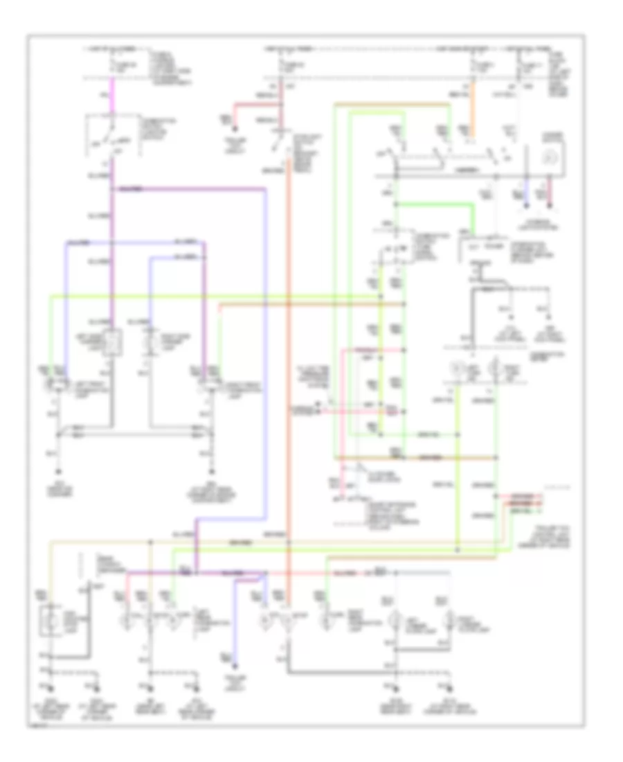
Headlights Wiring Diagram, without DRL for Nissan Xterra XE 2004
List of elements for Headlights Wiring Diagram, without DRL for Nissan Xterra XE 2004:
- 1st
- 2nd
- Anti-theft system
- Combination meter
- Combination switch (front fog lamp switch)
- Combination switch (lighting switch)
- E12 (near air cleaner)
- E45
- E47
- E54 (at right rear corner of engine compartment)
- E59
- Front fog lamp relay (in relay box)
- Fuse & fusible link box (at right side of engine compt)
- Fuse 37 15a
- Fuse 38 15a
- Fuse 40 15a
- Hi beam ind
- High
- Hot at all times
- Left front fog lamp
- Left headlamp
- Low
- M14 (at left kick panel)
- M38
- M68 (at right kick panel)
- Off
- Pass
- Red
- Right front fog lamp
- Right headlamp
HORN
Horn Wiring Diagram for Nissan Xterra XE 2004
List of elements for Horn Wiring Diagram for Nissan Xterra XE 2004:
- Anti-theft system (if equipped)
- Fuse & fusible link box (at right side of engine compt)
- Fuse 32 15a
- Horn
- Horn switch
- Horn relay (in relay box)
- Hot at all times
- Nca
- Spiral cable (under left side of dash)
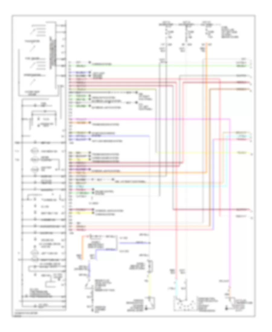
INSTRUMENT CLUSTER
Instrument Cluster Wiring Diagram (1 of 2) for Nissan Xterra XE 2004
List of elements for Instrument Cluster Wiring Diagram (1 of 2) for Nissan Xterra XE 2004:
- & a/t)
- (at right kick panel)
- (near air cleaner) e12
- (w/ 4-wheel drive
- (w/ 4-wheel drive)
- (w/ low tire pressure warning system) tire pressure ind
- (w/ vdc)
- (w/ vdc) slip
- (with speedometer & unified meter control unit
- 11p
- 4wd ind
- A/t fluid temp ind
- A/t fluid temperature switch (w/ 4wd & a/t)
- Abs ind
- Air bag ind
- Anti-lock brakes system
- Atp ind
- Brake fluid level switch (in brake fluid reservoir tank)
- Brake ind
- Charge ind
- Combination meter
- Cruise control system
- Cruise ind
- Diode 1 (behind left side of dash)
- Diode 3 (behind right side of dash)
- Door ind
- E49
- Exterior lights system
- Fuel gauge
- Fuel ind
- Fuse 10a
- Fuse 7.5a
- Fuse block (j/b) (at left side of dash, behind cover)
- Headlights system
- High beam ind
- Hot at all times
- Hot in on or start
- Interior lights system
- Left turn ind
- M14 (at left kick panel)
- M26
- M27
- M38
- M39
- M68
- M68 (at right kick panel)
- Malfunction ind
- Meter illum ind
- O/d off ind
- Odo/trip ind
- Odometer/trip meter)
- Oil ind
- Park/neutral position switch (a/t) (on right side of transmission)
- Parking brake switch (on base of parking brake lever)
- Right turn ind
- Seat belt ind
- Set ind
- Speedometer
- Starting/charging system
- Tachometer
- Transmissions system
- Vdc off
- W/ ascd
- W/ vdc
- W/o vdc
- Warning system
- Warning systen
- Washer ind
- Water temp gauge
- Wiper/washer system
Instrument Cluster Wiring Diagram (2 of 2) for Nissan Xterra XE 2004
List of elements for Instrument Cluster Wiring Diagram (2 of 2) for Nissan Xterra XE 2004:
- (at left kick panel) m14
- (at right kick panel) m68
- (near right rear seat) b106
- A/ bag w/l
- Air bag diagnosis sensor unit (under console box)
- Amb +
- Amb -
- Ambient air temperature sensor (at center front of engine compartment)
- B6 (near left rear seat)
- Back door switch (at lower left center of back door)
- Compass & thermometer
- D402 (at left rear corner of vehicle)
- Dim
- Ecm (below center of dash, behind lower cover)
- Fuel level sensor unit (at top of fuel tank)
- Gnd
- Hlmp
- Ign
- Interior lights system
- Led-r
- Left front door switch (at base of left "b" pillar)
- Left rear door switch (at left "c" pillar)
- Left seat belt buckle switch (in driver seat belt buckle assembly)
- M110
- M111
- M114
- Oil pressure switch (2.4l: on right side of engine, near oil filter) (3.3l: on lower left front of engine, near oil filter)
- Right front door switch (at right "b" pillar)
- Right rear door switch (at right "c" pillar)
- Smart entrance control unit (behind dash, right of steering column)
- Sped
- Tacho
- Thermal transmitter (2.4l: on right side of engine, forward of throttle body) (3.3l: on top front of engine, in water outlet)
- Vehicle speed sensor (2.4l: on bottom left rear of transmission) (3.3l: at right side of transfer case)
- W/ power door locks
- W/o power door locks
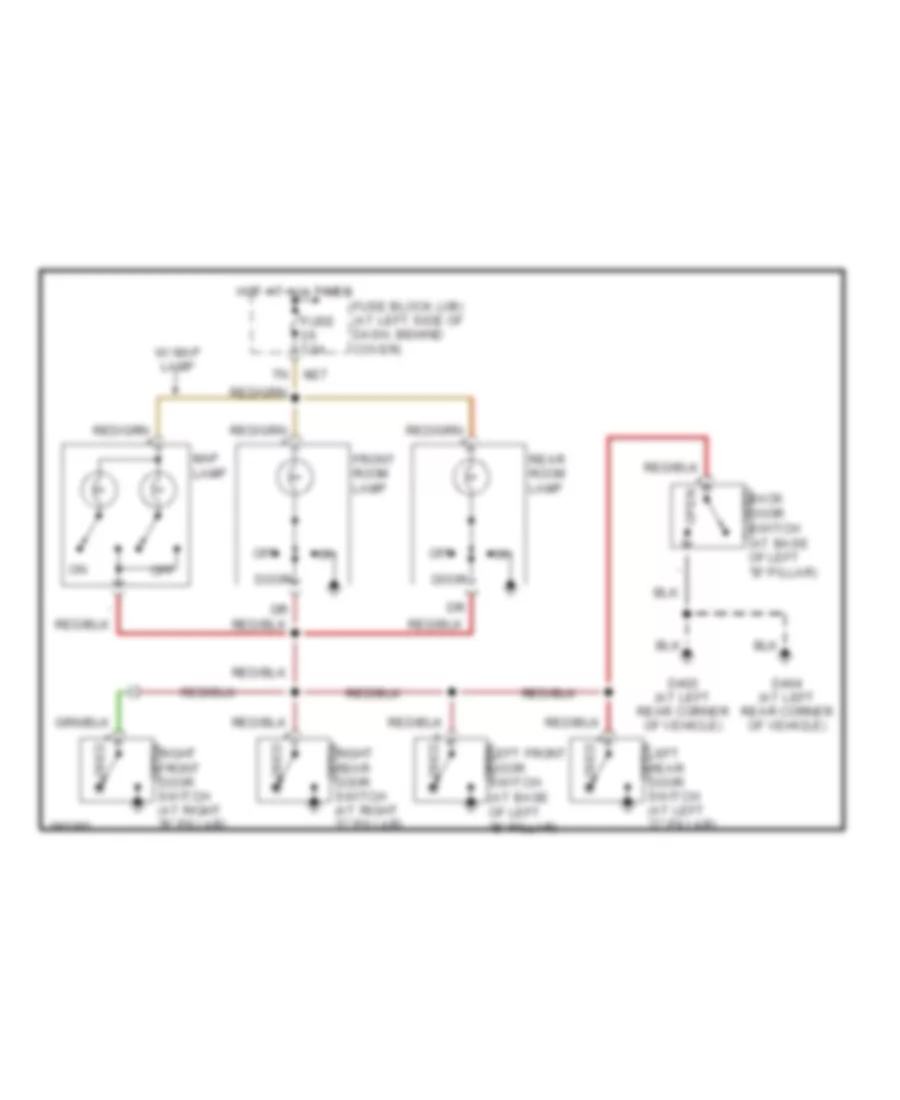
INTERIOR LIGHTS
Courtesy Lamps Wiring Diagram, with Power Door Locks for Nissan Xterra XE 2004
List of elements for Courtesy Lamps Wiring Diagram, with Power Door Locks for Nissan Xterra XE 2004:
- B10 (at left rear corner of vehicle)
- B6 (near left rear seat)
- Back door switch (at lower left center of back door)
- Bat (fuse)
- Bat saver out
- Central lock sw
- Central unlock sw
- Closed
- D402 (at left rear corner of vehicle)
- D404 (at left rear corner of vehicle)
- Door
- Door locks system
- Door sw (as)
- Door sw (dr)
- Door sw (rr)
- Front room lamp
- Fuse 7.5a
- Fuse block (j/b) (at left side of dash, behind cover)
- Gnd 1
- Gnd 2
- Hot at all times
- Hot in acc or on
- Ign
- Key cylinder sw (lock)
- Key cylinder sw (unlock)
- Left front door switch (at base of left "b" pillar)
- Left rear door switch (at left "c" pillar)
- M110
- M111
- M112
- M14 (at left kick panel)
- M26
- M27
- Map lamp (if equipped)
- Off
- Open
- Rear room lamp
- Right front door switch (at right "b" pillar)
- Right rear door switch (at right "c" pillar)
- Room lamp out
- Smart entrance control unit (behind dash, right of steering column)
Courtesy Lamps Wiring Diagram, without Power Door Locks for Nissan Xterra XE 2004
List of elements for Courtesy Lamps Wiring Diagram, without Power Door Locks for Nissan Xterra XE 2004:
- Closed
- Closed back door switch (at base of left "b" pillar)
- D402 (at left rear corner of vehicle)
- D404 (at left rear corner of vehicle)
- Door
- Front room lamp
- Fuse 7.5a
- Fuse block (j/b) (at left side of dash, behind cover)
- Hot at all times
- Left front door switch (at base of left "b" pillar)
- Left rear door switch (at left "c" pillar)
- M27
- Map lamp
- Off
- Open
- Rear room lamp
- Right front door switch (at right "b" pillar)
- Right rear door switch (at right "c" pillar)
- W/ map lamp
Instrument Illumination Wiring Diagram for Nissan Xterra XE 2004
List of elements for Instrument Illumination Wiring Diagram for Nissan Xterra XE 2004:
- (near base of a/t selector lever)
- 11p
- 1st
- 2nd
- A/t device (illumi- nation) (a/t)
- Air control (illumi- nation)
- Audio unit (illumi- nation)
- Combi- nation meter (illumi- nation)
- Combination switch (lighting switch)
- Compass & thermo- meter (illumi- nation) (w/ compass & thermometer)
- E45
- Fuse & fusible link box (at right side of engine compartment)
- Fuse 10a
- Fuse 15a
- Fuse block (j/b) (at left side of dash, behind cover)
- Hazard switch (illumi- nation)
- Hot at all times
- Hot in on or start
- Illumination control switch
- M14 (at left kick panel)
- M26
- M39
- M51
- M68 (at right kick panel)
- Main power window & door lock/ unlock switch (illumi- nation) (w/ power door locks)
- Meter
- Odo/ trip
- Off
POWER DISTRIBUTION
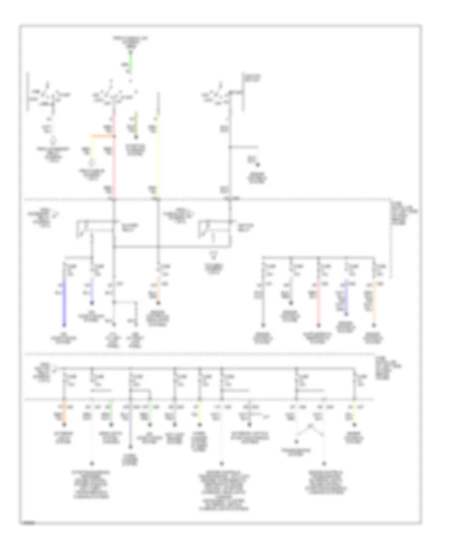
Power Distribution Wiring Diagram (1 of 2) for Nissan Xterra XE 2004
List of elements for Power Distribution Wiring Diagram (1 of 2) for Nissan Xterra XE 2004:
- (2.4l)
- (except 2.4l)
- (except 2.4l) (2.4l)
- 1n m27
- 2.4l
- 2p m26
- 30a
- 8n m27
- 9p m26
- Accessory relay
- Air conditioning & engine controls systems
- Anti-lock brakes system
- Anti-theft, power windows & warning systems (w/ power door lock)
- Battery
- Cigarette lighter socket
- Circuit breaker (behind lower left end of dash)
- D402 (at left rear corner of vehicle)
- Defogger system
- E50
- E52
- Engine controls & transmissions systems
- Engine controls, interior lights, transmissions & warning systems
- Engine controls, interior lights, warning, instrument cluster, door locks, anti-theft, transmissions, defogger, power windows & exterior lights systems
- Except 2.4l
- Exterior lights system
- Exterior lights, anti-lock brakes & cruise control systems
- Exterior lights, interior lights & warning systems
- From a battery (diagram 1 of 2)
- Front power socket 1
- Front power socket 2
- Fuse & fusible link box (at right side of engine compt)
- Fuse 10a
- Fuse 15a
- Fuse 20a
- Fuse 7.5a
- Fuse block (j/b) (at left side of dash, behind cover)
- Fuse g 20a
- Fusible link a 120a
- Fusible link a 80a
- Fusible link b 80a
- Fusible link c 40a
- Fusible link d 40a
- Fusible link e 40a
- Fusible link f 40a 30a
- Fusible link j 80a
- Headlights & anti-theft systems
- Headlights system
- Horns & anti-theft systems
- M14 (at left kick panel)
- M31
- M68 (at right kick panel)
- Mirrors & sound systems
- Power windows, door locks & anti-theft systems
- Rear power socket (at left rear corner of vehicle)
- Sound system
- Sound systems
- Starting/ charging system (2.4l)
- Starting/ charging system (except 2.4l)
- Starting/ charging system (w/ supercharger)
- To blower relay (diagram 2 of 2)
- To fuse b (diagram 1 of 2)
- To ignition relay (diagram 2 of 2)
- To ignition switch (diagram 2 of 2)
- W/ heavy duty electrical system
- W/ power door locks
Power Distribution Wiring Diagram (2 of 2) for Nissan Xterra XE 2004
List of elements for Power Distribution Wiring Diagram (2 of 2) for Nissan Xterra XE 2004:
- 10n
- 10p
- 11p m26
- 12p
- 12r
- 13p
- 16p
- 2n m27
- 7p m26
- 8r e49
- 9r e49
- A/t
- Acc
- Air conditioning system
- Anti-lock brakes system
- Blower relay
- E49
- E50
- Engine controls & headlights systems
- Engine controls system
- Engine controls, transmissions, exterior lights, cruise control, starting/charging & warning systems
- Exterior lights & starting/charging systems
- Exterior lights system
- From accessory d relay (diagram 1 of 2)
- From accessory relay (diagram 1 of 2)
- From fuse 29 (diagram 1 of 2)
- From fuse block c (diagram 1 of 2)
- From fusible link (diagram 1 of 2)
- From ignition g relay (diagram 2 of 2)
- Fuse 10a
- Fuse 15a
- Fuse 20a
- Fuse 7.5a
- Fuse block (j/b) (at left side of dash, behind cover)
- Headlights system (canada)
- Ignition relay
- Ignition switch
- Lock
- M/t
- M14 (at left kick panel)
- M26
- M27
- M31
- M68 (at right kick panel)
- Off
- On off
- Start
- Starting/ charging system
- Starting/charging, defogger, cruise control, power windows, anti-theft, transmissions & warning systems
- To fuse 2 (diagram 2 of 2)
- Transmissions system
- Wiper/ washer system
- Wiper/ washer system (w/ rear wiper)
POWER DOOR LOCKS
Power Door Locks Wiring Diagram for Nissan Xterra XE 2004
List of elements for Power Door Locks Wiring Diagram for Nissan Xterra XE 2004:
- (at left kick panel) m14
- (at left rear corner of vehicle) d402
- (at right kick panel) m68
- (near left rear seat) b6
- 1p m26
- Acc sw
- Anti- theft system
- Back door key cylinder switch (at lower right center of back door)
- Back door lock actuator (at lower right side of back door)
- Back door switch (at lower left center of back door)
- Bat (c/b)
- Bat (fuse)
- Between full stroke & n
- Central lock sw
- Central unlk sw
- Circuit breaker (behind lower left end of dash)
- Closed
- D402 (at left rear corner of vehicle)
- Door lock out (all)
- Door sw (as)
- Door sw (dr)
- Door sw (rr)
- Door unlk out (as, rr)
- Door unlk out (dr)
- Exterior lights system
- Flasher lh out
- Flasher rh out
- Full stroke
- Fuse 10a
- Fuse 7.5a
- Fuse block (j/b) (at left side of dash, behind cover)
- Gnd1
- Gnd2
- Headlamps out
- Horn out
- Hot at all times
- Hot in acc or on
- Hot in on or start
- Ign sw
- Inserted
- Interior lights system
- Key cyl lock sw
- Key cyl unlk sw
- Key sw
- Key switch
- Left front door key cylinder switch
- Left front door lock actuator (at rear of left front door)
- Left front door switch (at base of left "b" pillar)
- Left rear door lock actuator (at rear of left rear door)
- Left rear door switch (at left "c" pillar)
- Lock
- Lock switch
- M110
- M111
- M112
- M27
- Main power window & door lock/ unlock switch
- Open
- Red
- Removed
- Right door lock/ unlock switch
- Right front door lock actuator (at rear of right front door)
- Right front door switch (at right "b" pillar)
- Right rear door lock actuator (at rear of right rear door)
- Right rear door switch (at right "c" pillar)
- Room lamp bat sav out
- Room lamp out
- Smart entrance control unit (behind dash, right of steering column)
- Unlock
- Unlock switch
POWER MIRRORS
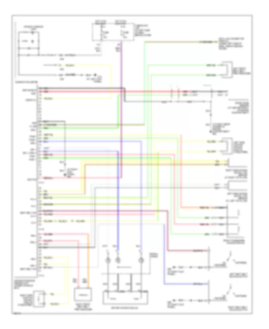
Power Mirrors Wiring Diagram for Nissan Xterra XE 2004
List of elements for Power Mirrors Wiring Diagram for Nissan Xterra XE 2004:
- Change over switch
- Door mirror remote control switch
- Fuse 18 10a
- Fuse block (at left side of dash, behind cover)
- Hot in acc or on
- Left side door mirror
- Left/right motor
- M14 (frontier: at left ``a" pillar) (xterra: at left kick panel)
- M26
- Mirror switch
- Off
- Right side door mirror
- Up/down motor
POWER WINDOWS
Power Windows Wiring Diagram for Nissan Xterra XE 2004
List of elements for Power Windows Wiring Diagram for Nissan Xterra XE 2004:
- Auto amp
- Auto d
- B10 (at left rear corner of vehicle)
- B6 (near left rear seat)
- Bat (cb)
- Bat (fuse)
- Circuit breaker
- Circuit breaker (behind lower left end of dash)
- Door sw (as)
- Door sw (dr)
- Fuse 7.5a
- Fuse block (j/b) (at left side of dash, behind cover)
- Gnd1
- Gnd2
- Hot at all times
- Hot in acc or on
- Ign sw
- Left front door switch
- Left front power window motor (at center of left front door)
- Left rear power window motor (at center of left rear door)
- Left rear power window switch
- Left rear switch
- M110
- M111
- M112
- M14 (at left kick panel)
- M26
- M27
- M68 (at right kick panel)
- Main power window & door lock/unlock switch
- Nca
- Power window relay (behind lower left end of dash)
- Rap output
- Right front door switch
- Right front power window motor (at center of left front door)
- Right front power window switch
- Right front switch
- Right rear power window motor (at center of right rear door)
- Right rear power window switch
- Right rear switch
- Smart entrance control unit (behind dash, right of steering column)
- Unlk
- Window lock switch
RADIO
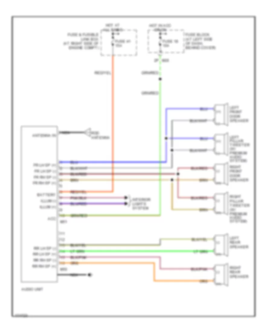
Radio Wiring Diagram, with Amplifier for Nissan Xterra XE 2004
List of elements for Radio Wiring Diagram, with Amplifier for Nissan Xterra XE 2004:
- (+)
- (-)
- + -
- 2.4l 3.3l
- Acc
- Amp on
- Antenna in
- Audio amplifier (behind center of dash)
- Audio unit
- Bat
- Battery
- Fr lh in (+)
- Fr lh in (-)
- Fr lh sp (+)
- Fr lh sp (-)
- Fr rh in (+)
- Fr rh in (-)
- Fr rh sp (+)
- Fr rh sp (-)
- Fuse & fusible link box (at right side of engine compartment)
- Fuse 18 10a
- Fuse 33 20a
- Fuse 41 15a
- Fuse block (at left side of dash, behind cover)
- Gnd
- Hot at all times
- Hot in acc or on
- Illum (+)
- Illum (-)
- Interior lights system
- Left front door speaker
- Left pillar tweeter
- Left rear speaker
- M118
- M132
- M133
- M26
- M50
- M51
- M68 (at right kick panel)
- Mode
- Nca
- Next
- Pnk
- Prev
- Red
- Right front door speaker
- Right pillar tweeter
- Right rear speaker
- Rl sp out (+)
- Rl sp out (-)
- Rod antenna
- Rr lh in (+)
- Rr lh in (-)
- Rr lh sp (+)
- Rr lh sp (-)
- Rr rh in (+)
- Rr rh in (-)
- Rr rh sp (+)
- Rr rh sp (-)
- Rr sp out (+)
- Rr sp out (-)
- Spiral cable (under left side of dash)
- Steering sw +
- Steering sw -
- Steering wheel audio control switches
- Subwoofer (if equipped)
- Switched b+
- Vol dn
- Vol up
- W/ subwoofer
- W/o subwoofer
Radio Wiring Diagram, without Amplifier for Nissan Xterra XE 2004
List of elements for Radio Wiring Diagram, without Amplifier for Nissan Xterra XE 2004:
- (+)
- (-)
- Acc
- Antenna in
- Audio unit
- Battery
- Fr lh sp (+)
- Fr lh sp (-)
- Fr rh sp (+)
- Fr rh sp (-)
- Fuse & fusible link box (at right side of engine compt)
- Fuse 18 10a
- Fuse 41 15a
- Fuse block (at left side of dash, behind cover)
- Hot at all times
- Hot in acc or on
- Illum (+)
- Illum (-)
- Interior lights system
- Left front door speaker
- Left pillar tweeter (w/ premium audio system)
- Left rear speaker
- M26
- M50
- M51
- Nca
- Right front door speaker
- Right pillar tweeter (w/ premium audio system)
- Right rear speaker
- Rod antenna
- Rr lh sp (+)
- Rr lh sp (-)
- Rr rh sp (+)
- Rr rh sp (-)
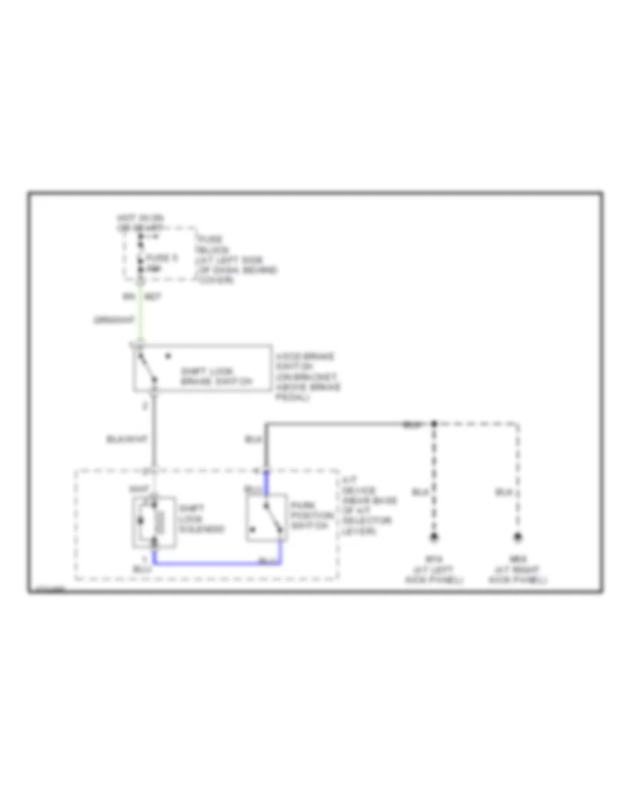
SHIFT INTERLOCK
Shift Interlock Wiring Diagram for Nissan Xterra XE 2004
List of elements for Shift Interlock Wiring Diagram for Nissan Xterra XE 2004:
- A/t device (near base of a/t selector lever)
- Ascd brake switch (on bracket, above brake pedal)
- Fuse 5 10a
- Fuse block (at left side of dash, behind cover)
- Hot in on or start
- M14 (at left kick panel)
- M27
- M68 (at right kick panel)
- Park position switch
- Shift lock brake switch
- Shift lock solenoid
STARTING/CHARGING
2.4L
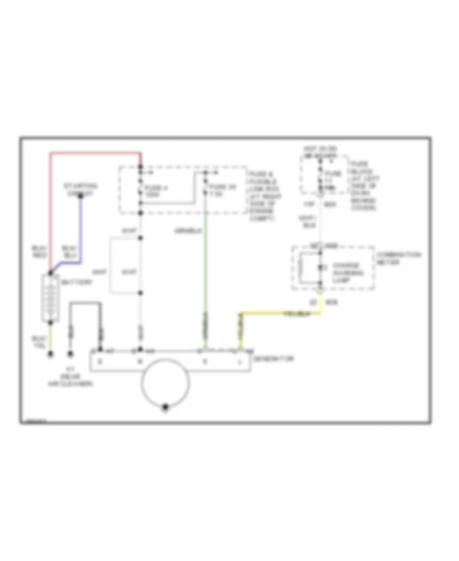
2.4L, Charging Wiring Diagram for Nissan Xterra XE 2004
List of elements for 2.4L, Charging Wiring Diagram for Nissan Xterra XE 2004:
- 11p
- Battery
- Charge warning lamp
- Combination meter
- E200
- E203 (near relay box)
- E206
- E207
- E208
- E25 r2
- E31
- Fuse &
- Fuse 10a
- Fuse 36 7.5a
- Fuse a 80a
- Fuse block (at left side of dash, behind cover)
- Fusible
- Generator
- Hot in on or start
- Link box (at right side of engine compt)
- M26
- M38
- M39
- Starting circuit
2.4L, Starting Wiring Diagram for Nissan Xterra XE 2004
List of elements for 2.4L, Starting Wiring Diagram for Nissan Xterra XE 2004:
- 9r e49
- Acc
- Battery
- Clutch interlock relay (in relay box)
- Clutch interlock switch (on bracket, above clutch pedal)
- Fuse & fusible link box (at right side of engine compt)
- Fuse 10a
- Fuse block (at left side of dash, behind cover)
- Fuse e 40a
- Hot at all times
- Hot in on or start
- Ignition switch
- Lock
- M14 (at left kick panel)
- Nca
- Off
- Power distribution system
- Start
- Starter motor
3.3L
3.3L, Charging Wiring Diagram for Nissan Xterra XE 2004
List of elements for 3.3L, Charging Wiring Diagram for Nissan Xterra XE 2004:
- 11p
- A1 (near air cleaner)
- Battery
- Charge warning lamp
- Combination meter
- Fuse & fusible link box (at right side of engine compt)
- Fuse 10a
- Fuse 36 7.5a
- Fuse a 120a
- Fuse block (at left side of dash, behind cover)
- Generator
- Hot in on or start
- M26
- M38
- M39
- Starting circuit
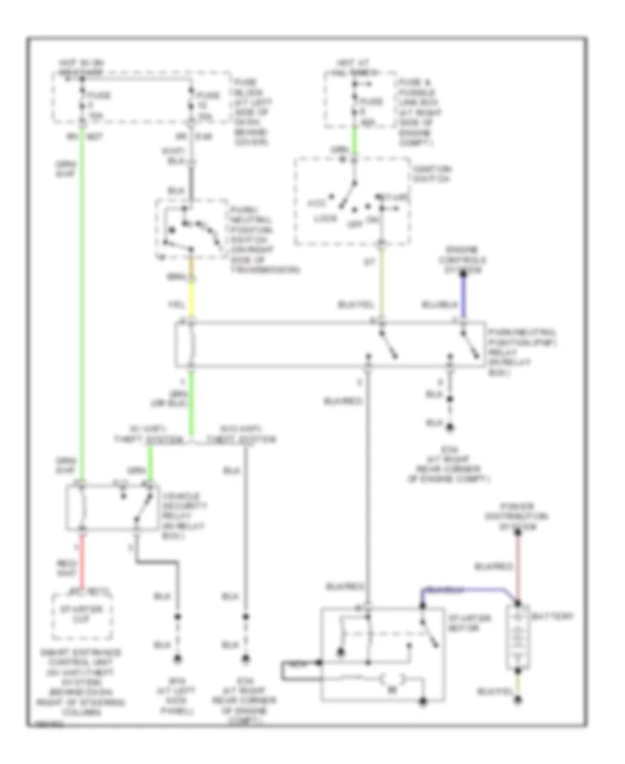
3.3L, Starting Wiring Diagram, A/T for Nissan Xterra XE 2004
List of elements for 3.3L, Starting Wiring Diagram, A/T for Nissan Xterra XE 2004:
- 6r e49
- 9n m27
- Acc
- Battery
- E54 (at right rear corner of engine compt)
- Engine controls system
- Fuse & fusible link box (at right side of engine compt)
- Fuse 10a
- Fuse block (at left side of dash, behind cover)
- Fuse e 40a
- Hot at all times
- Hot in on or start
- Ignition switch
- Lock
- M111
- M14 (at left kick panel)
- Nca
- Off
- Park/ neutral position switch (on right side of transmission)
- Park/neutral position (pnp) relay (in relay box)
- Power distribution system
- Smart entrance control unit (w/ anti-theft system) (behind dash, right of steering column)
- Start
- Starter cut
- Starter motor
- Vehicle security relay (in relay box)
- W/ anti- theft system
- W/o anti- theft system
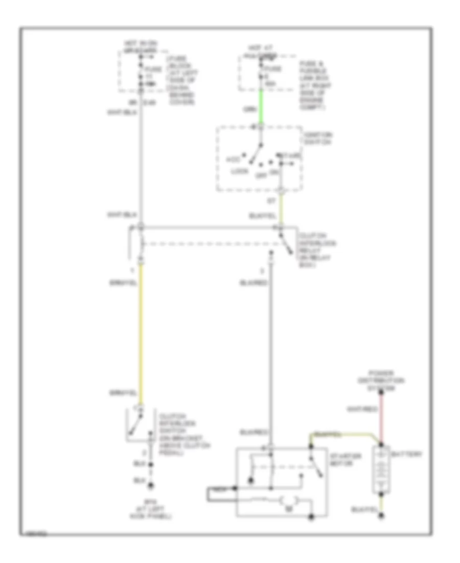
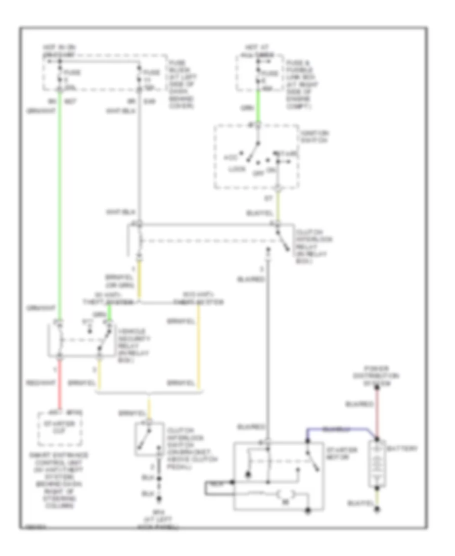
3.3L, Starting Wiring Diagram, M/T for Nissan Xterra XE 2004
List of elements for 3.3L, Starting Wiring Diagram, M/T for Nissan Xterra XE 2004:
- Acc
- Battery
- Clutch interlock relay (in relay box)
- Clutch interlock switch (on bracket, above clutch pedal)
- E49
- Fuse & fusible link box (at right side of engine compt)
- Fuse 10a
- Fuse block (at left side of dash, behind cover)
- Fuse e 40a
- Hot at all times
- Hot in on or start
- Ignition switch
- Lock
- M111
- M14 (at left kick panel)
- M27
- Nca
- Off
- Power distribution system
- Smart entrance control unit (w/ anti-theft system) (behind dash, right of steering column)
- Start
- Starter cut
- Starter motor
- Vehicle security relay (in relay box)
- W/ anti- theft system
- W/o anti- theft system
SUPPLEMENTAL RESTRAINTS
Supplemental Restraints Wiring Diagram for Nissan Xterra XE 2004
List of elements for Supplemental Restraints Wiring Diagram for Nissan Xterra XE 2004:
- (at right kick panel) m68
- (under left side of dash, near fuse box cover)
- 11p
- A/bag w/l
- Air bag diagnosis sensor unit (under console box)
- Air bag warning lamp
- Clh +
- Clh -
- Combination meter
- Corner of engine compartment) e54
- Crash zone sensor (at center front of engine compartment)
- Crh +
- Crh -
- Czs +
- Czs -
- Data link connector (partial)
- Dr1 (-) dr2 (-)
- Dr1 +
- Dr2 +
- Driver air bag module
- Fastened
- Front passenger air bag module
- Fuse 10a
- Fuse block (j/b) (at left side of dash, behind cover)
- Gnd
- Gnd (shield)
- Hot in on or start
- Ignition
- K-line
- Left front seat belt pre-tensioner
- Left seat belt buckle switch
- Left side air bag (satellite) sensor (at left "b" pillar)
- Left side curtain air bag module (if equipped)
- M113
- M114
- M115
- M14 (at left kick panel)
- M202
- M206
- M38
- M39
- M68 (at right kick panel)
- Nca
- Pas1 +
- Pas1 -
- Pas2 +
- Pas2 -
- Plh +
- Plh -
- Prh +
- Prh -
- Red
- Right front seat belt pre-tensioner
- Right seat belt buckle switch
- Right side air bag (satellite) sensor (at right "b" pillar)
- Right side curtain air bag module (if equipped)
- Seat belt sw
- Spiral cable
- Un- fastened
TRANSMISSION
3.3L
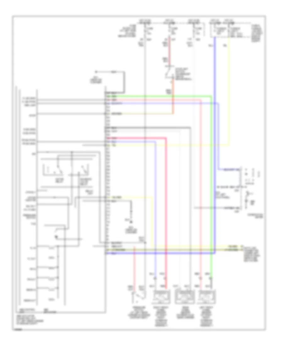
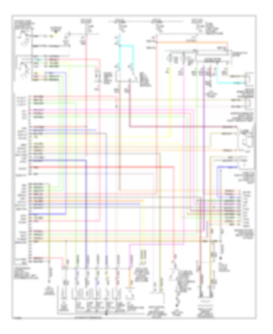
3.3L, A/T Wiring Diagram for Nissan Xterra XE 2004
List of elements for 3.3L, A/T Wiring Diagram for Nissan Xterra XE 2004:
- (on right side of transmission) park/neutral position switch
- 1-sw
- 11p
- 2-sw
- A/t device (overdrive control switch) (on steering column, below selector lever)
- A/t fluid temp ind
- A/t fluid temp sensor
- A/t fluid temperature switch
- Acsd 4th
- Ascd control unit (behind dash, left of steering column)
- Atck
- Automatic transaxle
- Avcc
- Closed throttle
- Combination meter
- Crui acsd
- D-sw
- Data in
- Data link connector (at left side of dash, near fuse box cover)
- Data out
- Diode 2 (behind left side of dash)
- Dropping resistor (right front corner of engine compt, near battery)
- Dt1
- Dt2
- Dt3
- Ecm relay (below center of dash, near ecm)
- Engine control module (ecm) (below center
- F11 (top of intake manifold)
- Fld temp
- Full sw
- Fuse 10a
- Fuse 7.5a
- Fuse block (left side of dash, behind cover)
- Gnd
- Gnd-a
- Hot at all times
- Hot in on or start
- Idle sw
- Line press sol valve
- Lu duty
- M14 (left kick panel)
- Mem b/u
- Nca
- O/d ind
- O/d off ind
- O/d sw
- Obd2
- Of dash)
- Over- run clutch sol
- Ovr/c
- P/n-sw
- Pl duty
- Pnk
- R-sw
- Red
- Revolution sensor (left side of transmission)
- Sen pwr
- Sens gnd
- Shift a
- Shift b
- Shift sol valve a
- Shift sol valve b
- Ss off
- Starting system
- Tacho
- Tcc sol valve
- Th sens
- Throttle position sensor & switch (on throttle body)
- Transmission control module (tcm) (behind dash, left of steering column)
- Tvo
- Tvoo
- Unified meter control unit
- Vehicle speed sensor (on top of transmission)
- Vign
- Vsp
- Vsp-1
- Vsp-2
- Wot
3.3L SC
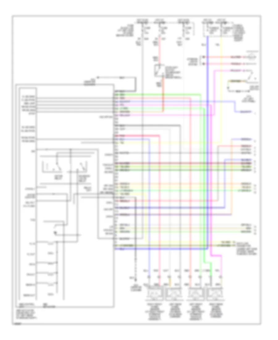
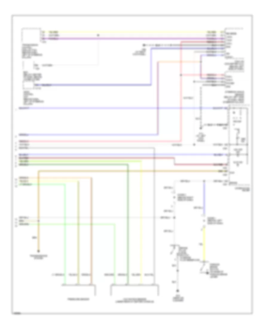
3.3L SC, A/T Wiring Diagram for Nissan Xterra XE 2004
List of elements for 3.3L SC, A/T Wiring Diagram for Nissan Xterra XE 2004:
- (on right side of transmission) park/neutral position switch
- 1-sw
- 11p
- 2-sw
- A/t device (overdrive control switch) (on the steering column, below selector lever)
- A/t fluid temp ind
- A/t fluid temp sensor
- A/t fluid temp switch (4wd)
- Acsd 4th
- Ascd control unit (behind dash, left of steering column)
- Atck
- Atsa
- Automatic transaxle
- Avcc
- Closed throttle
- Combination meter
- Crui acsd
- D-sw
- Data in
- Data link connector (left side of dash, near fuse box cover)
- Data out
- Diode 2 (behind left side of dash)
- Dropping resistor (right front corner of engine compt, near battery)
- Dt1
- Dt2
- Dt3
- Ecm relay (below center dash, near ecm)
- Engine control module (ecm) (below center
- F11 (top of intake manifold)
- Fld temp
- Full sw
- Fuse 10a
- Fuse 15a
- Fuse 7.5a
- Fuse block (left side of dash, behind cover)
- Gnd
- Gnd-a
- Hot at all times
- Hot in on or start
- Idle sw
- Line press sol valve
- Lu duty
- M14 (left kick panel)
- Mem b/u
- Nca
- O/d ind
- O/d off ind
- O/d sw
- Obd2
- Of dash)
- Over- run clutch sol
- Ovr/c
- P/n-sw
- Pl duty
- Pnk
- R-sw
- Red
- Revolution sensor (left side of trans- mission)
- Sen pwr
- Sens gnd
- Shift a
- Shift b
- Shift sol valve a
- Shift sol valve b
- Ss off
- Starting system
- Stop lamp switch (on bracket, above brake pedal)
- Stop sw
- Tacho
- Tcc sol valve
- Th sens
- Throttle position sensor & switch (on throttle body)
- Transmission control module (tcm) (behind dash, left of steering column)
- Tss
- Turbine revolution sensor (top of trans- mission)
- Tvo
- Tvoo
- Unified meter control unit
- Vehicle speed sensor (on top of transmission)
- Vign
- Vsp
- Vsp-1
- Vsp-2
- W/ 4wd
- Wot
WARNING SYSTEMS
Buzzer Wiring Diagram, with Power Door Locks for Nissan Xterra XE 2004
List of elements for Buzzer Wiring Diagram, with Power Door Locks for Nissan Xterra XE 2004:
- 11p
- 1st
- 2nd
- B6 (near left rear seat)
- Bat
- Batt
- Circuit breaker (behind lower left end of dash)
- Combination meter
- Combination switch (lighting switch)
- Door ind
- Fuse & fusible link box (at right side of engine compartment)
- Fuse 10a
- Fuse 15a
- Fuse 7.5a
- Fuse block (j/b) (at left side of dash, behind cover)
- Fuse f 40a
- Ground 1
- Ground 2
- Hot at all times
- Hot in on or start
- Ignition
- Key in ign sw
- Key switch
- Left door sw
- Left front door switch (at base of left "b" pillar)
- Left seat belt buckle switch (in driver seat belt buckle assembly)
- Light sw
- M110
- M111
- M112
- M14 (at left kick panel)
- M26
- M27
- M39
- M68 (at right kick panel)
- Off
- Power windows system
- Seat belt ind
- Seat belt sw
- Smart entrance control unit (behind dash, right of steering column)
Buzzer Wiring Diagram, without Power Door Locks for Nissan Xterra XE 2004
List of elements for Buzzer Wiring Diagram, without Power Door Locks for Nissan Xterra XE 2004:
- 11p
- 1st
- 2nd
- B6 (near left rear seat)
- Comb sw
- Combination meter
- Combination switch (lighting switch)
- Door ind
- Fuse & fusible link box (at right side of engine compartment)
- Fuse 10a
- Fuse 15a
- Fuse 7.5a
- Fuse block (at left side of dash, behind cover)
- Ground
- Hot at all times
- Hot in on or start
- Ignition
- Instrument cluster system
- Key in ign sw
- Key switch
- Left door sw
- Left front door switch (at base of left "b" pillar)
- Left seat belt buckle switch
- M14 (at left kick panel)
- M26
- M27
- M39
- Off
- Seat belt ind
- Seat belt sw
- Warning chime unit (behind left side of dash)
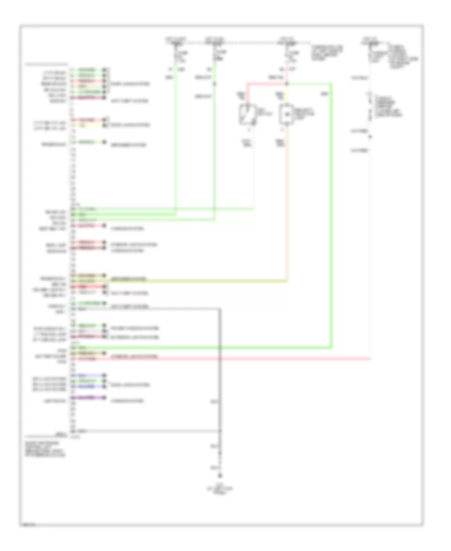
Tire Pressure Monitoring Wiring Diagram for Nissan Xterra XE 2004
List of elements for Tire Pressure Monitoring Wiring Diagram for Nissan Xterra XE 2004:
- (with odo/ trip meter)
- 11p
- Batt
- Combination meter
- Data link connector (under left side of dash, near fuse box cover)
- Diag-id input
- Exterior lights system
- Fuse 10a
- Fuse 7.5a
- Fuse block (j/b) (at left side of dash, behind cover)
- Ground
- Hazard
- Hazard switch
- Hot at all times
- Hot in on or start
- Ign 1
- Ign 2
- Led
- Low tire pressure warning check connector
- Low tire pressure warning control unit (behind dash, right of steering column)
- Low tire pressure warning relay (behind center of dash)
- M26
- M27
- M38
- M39
- M68 (at right kick panel)
- Speed input
- Tire pressure ind
- Unified meter control unit
WIPER/WASHER
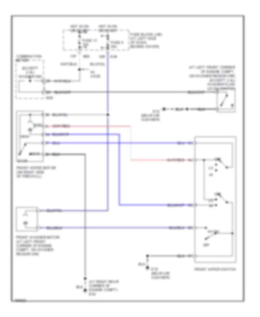
2-Speed Front Wiper/Washer Wiring Diagram for Nissan Xterra XE 2004
List of elements for 2-Speed Front Wiper/Washer Wiring Diagram for Nissan Xterra XE 2004:
- (at left front corner of engine compt, on washer reservoir) (except 2.4l) washer fluid level switch
- (at right rear corner of engine compt) e54
- (except 2.4l) washer ind
- 11p
- 12r
- Combination
- E12 (near air cleaner)
- E49
- Front washer motor (at left front corner of engine compt, on washer reservoir)
- Front wiper motor (on right side of firewall)
- Front wiper switch
- Fuse 11 10a
- Fuse 6 20a
- Fuse block (j/b) (at left side of dash, behind cover)
- High
- Hot in on or start
- Low
- M26
- M39
- Meter
- Move
- Off
- Stop
- W/ ascd
- Wash
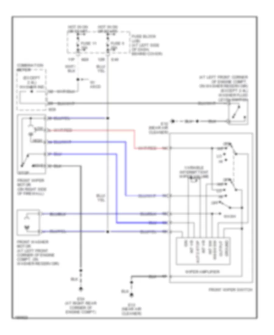
Intermittent Wiper/Washer Wiring Diagram for Nissan Xterra XE 2004
List of elements for Intermittent Wiper/Washer Wiring Diagram for Nissan Xterra XE 2004:
- (at left front corner of engine compt, on washer reservoir) (except 2.4l) washer fluid level switch
- (except 2.4l) washer ind
- 11p
- 12r
- Auto stop
- Combination meter
- E12 (near air cleaner)
- E49
- E54 (at right rear corner of engine compt)
- Front washer motor (at left front corner of engine compt, on washer reservoir)
- Front wiper motor (on right side of firewall)
- Front wiper switch
- Fuse 11 10a
- Fuse 6 20a
- Fuse block (j/b) (at left side of dash, behind cover)
- Ground
- High
- Hot in on or start
- Ign
- Int
- Int vr
- Low
- M26
- M39
- Move
- Off
- Output
- Stop
- Variable intermittent wiper volume
- W/ ascd
- Wash
- Wash sw int sw
- Wiper amplifier
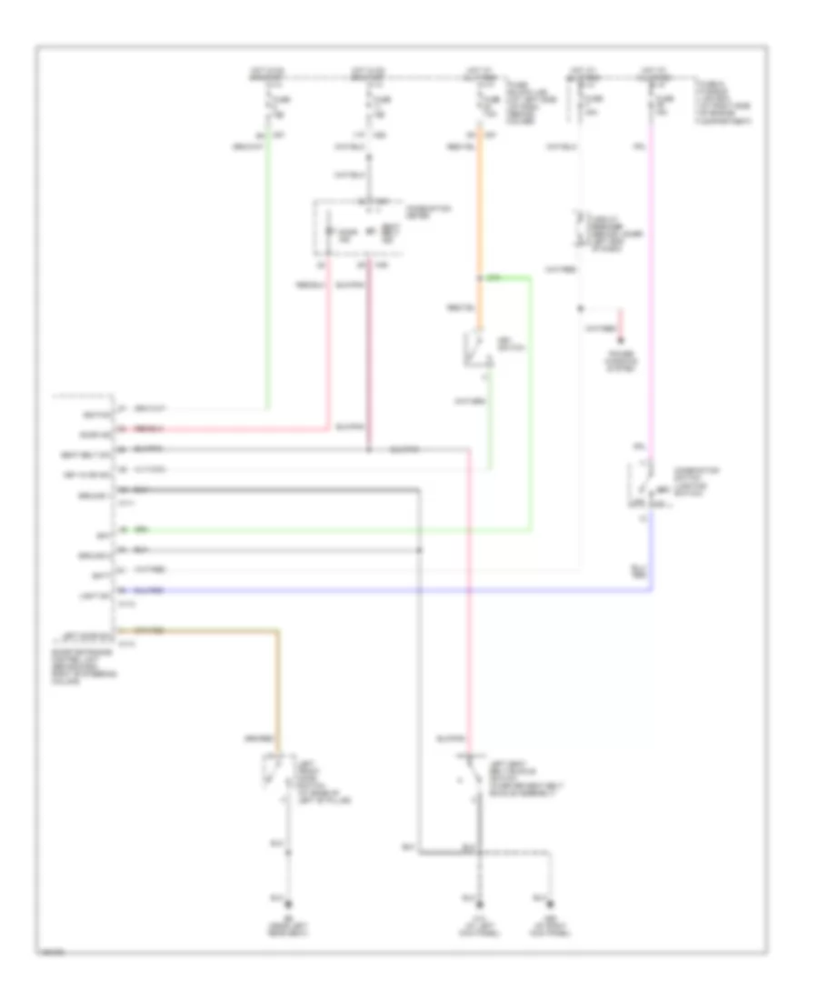
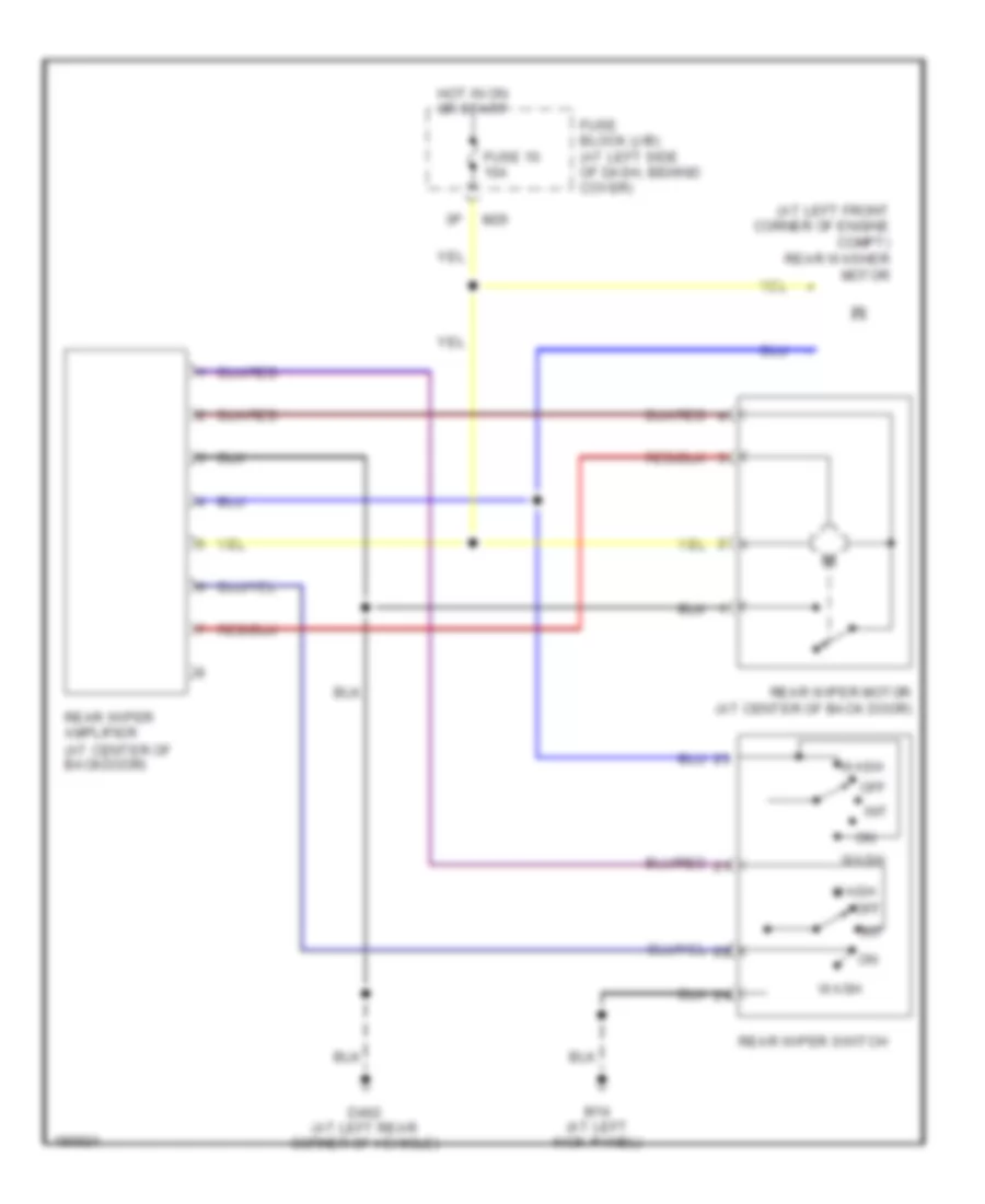
Rear Wiper/Washer Wiring Diagram for Nissan Xterra XE 2004
List of elements for Rear Wiper/Washer Wiring Diagram for Nissan Xterra XE 2004:
- (at left front corner of engine compt) rear washer motor
- D402 (at left rear corner of vehicle)
- Fuse 10 10a
- Fuse block (j/b) (at left side of dash, behind cover)
- Hot in on or start
- Int
- M14 (at left kick panel)
- M26
- Off
- Rear wiper amplifier (at center of backdoor)
- Rear wiper motor (at center of back door)
- Rear wiper switch
- Wash

 Čeština
 Dansk
Dansk Deutsch
 Ελληνικά
 English
 Español
 Suomi
Suomi Français
 Français
 עברית
עברית Hrvatski
 Magyar
 Italiano
 日本語
日本語 한국어
한국어 Nederlands
 Polski
 Português
 Português
 Română
 Русский
 Slovenčina
 Slovenščina
 Svenska
 Türkçe
 中文 (中国)