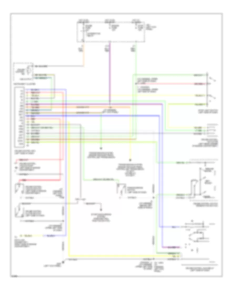
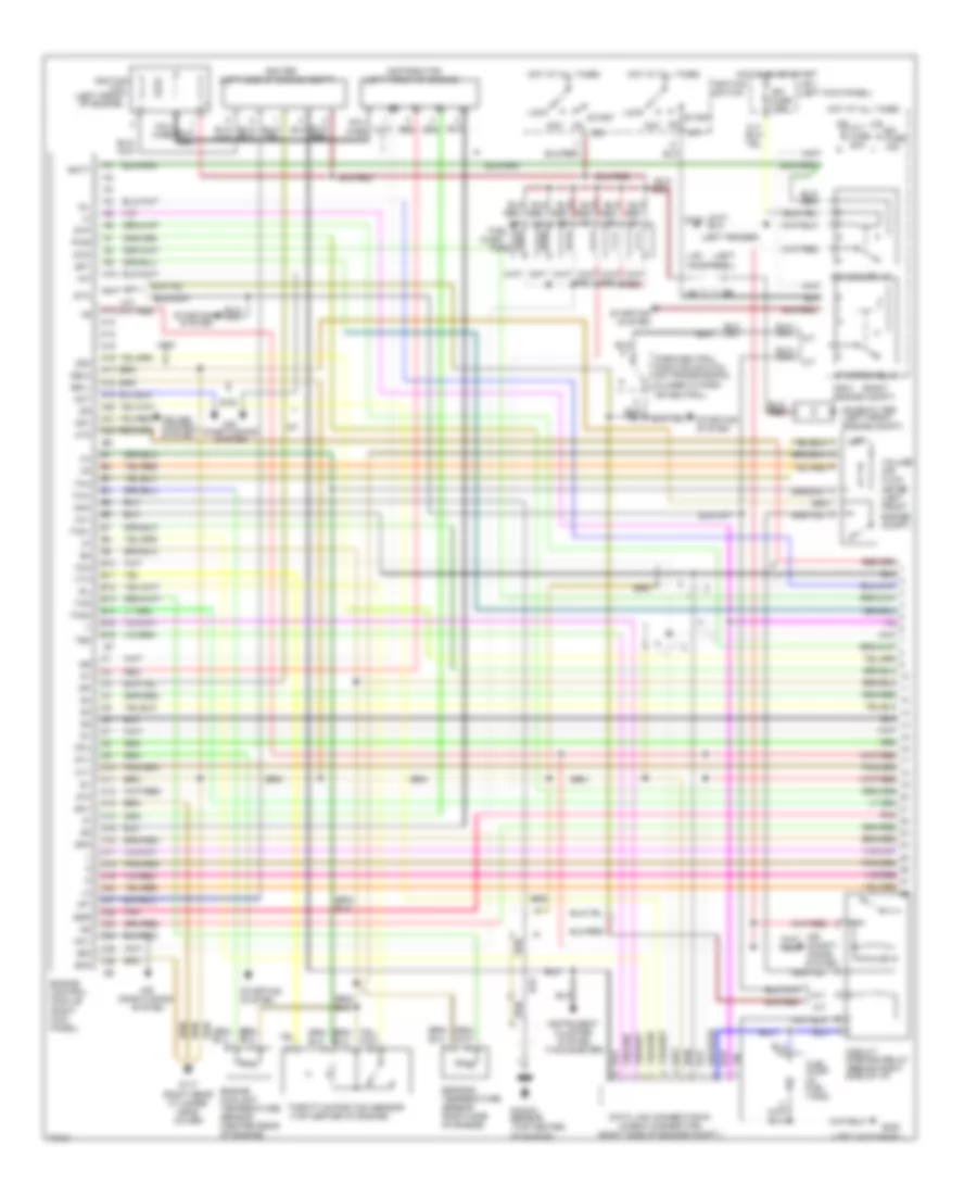
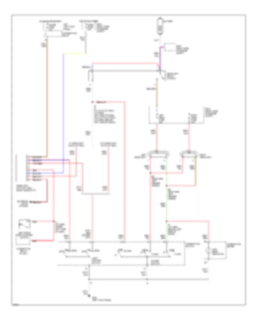
AIR CONDITIONING
A/C Wiring Diagram for Toyota 4Runner SR5 1995
 https://portal-diagnostov.com/license.html
Automotive Electricians Portal FZCO
Automotive Electricians Portal FZCO
https://portal-diagnostov.com/license.html
https://portal-diagnostov.com/license.html
Automotive Electricians Portal FZCO
Automotive Electricians Portal FZCO
List of elements for A/C Wiring Diagram for Toyota 4Runner SR5 1995:
- (2.4l)
- (3.0l)
- 1994 vftc c
- 3.0l a/t w/ 4wd
- 3.0l only
- A/c
- A/c amplifier (right side of i/p)
- A/c condenser fan motor (front of engine compt)
- A/c condenser fan relay no. 1
- A/c condenser fan relay no. 2
- A/c cut relay (right side of i/p)
- A/c dual pressure switch (right side of i/p)
- A/c fuse 10a
- A/c idle- up valve (right rear of engine compt)
- A/c magnetic clutch (right front of engine compt)
- A/c single pressure switch (right side of i/p)
- A/c switch
- A/c thermistor (right side of i/p)
- A24
- Act
- Acv
- All others
- B10
- B19
- B6 a4
- Blower motor (right side of i/p)
- Blower resistor (right side of i/p)
- Blower switch
- Cds fan fusible link 30a
- Engine control module (right side of i/p)
- Engine controls system (efi main relay)
- Front heater relay
- G108 (left side of radiator)
- G200 (left kick panel)
- Gauge fuse 10a
- Heater fuse 40a
- Hot at all times
- Hot in on or start
- Igniter (left side of engine compt)
- Integration relay
- Interior lights system (rheostat)
- Interior lights system (tail fuse)
- J/b 1 (left kick panel)
- Off
- Pnk
- R/b 3 (right kick panel)
- R/b 3 (right side of glove box)
- R/b 4 (right side of engine compt)
- Red
- Resistor (front of engine compt)
- Water temperature switch (center rear of engine compt)
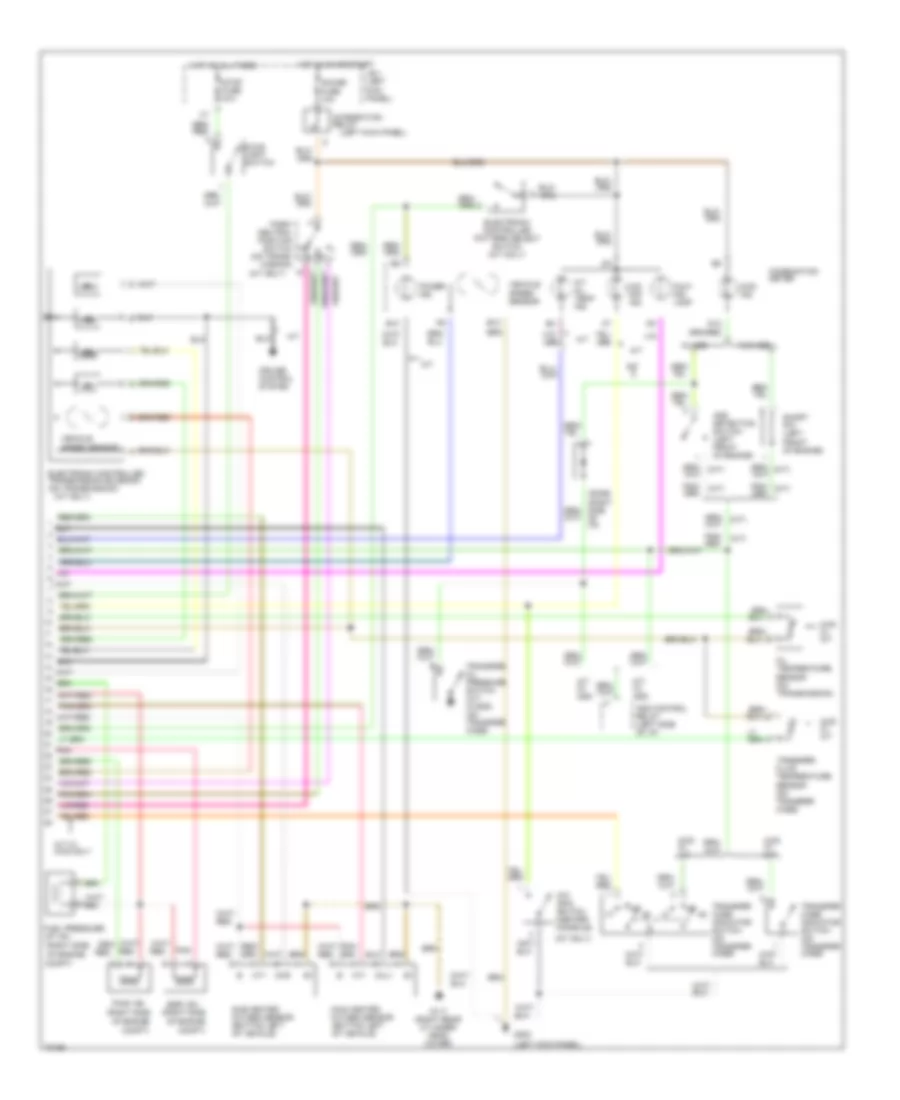
Heater Wiring Diagram for Toyota 4Runner SR5 1995
List of elements for Heater Wiring Diagram for Toyota 4Runner SR5 1995:
- (left kick panel)
- Blower motor (right side of i/p)
- Blower resistor (right side of i/p)
- Blower switch
- C 1995 vftc
- Front heater relay
- G200
- Gauge fuse 10a
- Heater fuse 40a
- Hot at all times
- Hot in on or start
- Integration relay
- Interior lights system (rheostat)
- Interior lights system (tail fuse)
- J/b 1 (left kick panel)
- Off
- R/b 3 (right kick panel)
- R/b 3 (right side of glove box)
- Red
Rear Heater Wiring Diagram for Toyota 4Runner SR5 1995
List of elements for Rear Heater Wiring Diagram for Toyota 4Runner SR5 1995:
- 1994 vftc c
- Blower motor
- Blower resistor
- Blower switch
- G200 (left kick panel)
- G203 (right kick panel)
- Gauge fuse 10a integration relay
- Heater fuse 20a
- Hot at all times
- Hot in on or start
- J/b 1 (left kick panel)
- Low
- Off
- R/b 3 (right kick panel)
- Rear heater
- Rear heater relay
ANTI-LOCK BRAKES
All-Wheel ABS Wiring Diagram for Toyota 4Runner SR5 1995
List of elements for All-Wheel ABS Wiring Diagram for Toyota 4Runner SR5 1995:
- (i/p harn, upper right side of dash)
- (i/p harn, upper right side of dash) (usa) i9 (canada) i8
- (i/p harness, upper right side of dash) i9 (canada)
- 4wd ind
- A10
- A11
- A12
- A13
- A14
- A15
- A16
- A17
- A18
- A19
- A20
- A21
- A22
- A23
- A24
- A25
- A26
- Abs actuator (left rear of engine compartment)
- Abs check connector (right rear corner of engine compartment)
- Abs deceleration sensor (below center console)
- Abs ecu (below center of i/p)
- Abs fuse 60a
- Abs relay (right side of engine compartment)
- Abs warning ind
- Ast
- B10
- B11
- B12
- B13
- B14
- B15
- B16
- Bat
- Brake fluid level switch
- Combination meter
- Data link connector 1 (right side of engine compartment)
- Dome fuse 15a
- Ecu-ig fuse 20a
- Ex1
- Fl+
- Fl-
- Fr+
- Fr-
- Fss
- G117 (right cylinder head rear cover)
- G200 (left kick panel)
- Gauge fuse 10a
- Ggnd
- Gnd
- Gs1
- Gs2
- Gst
- Hot at all times
- Hot in on
- I11
- I15
- I20
- I7 (usa) (i/p harness, behind combiniation meter)
- I8 (i/p harn, upper right side of dash)
- I9 (i/p harn, upper right side of dash)
- Ig1
- Integration relay
- J/b 1 (left kick panel)
- Left front abs speed sensor
- Left rear abs speed sensor
- Light
- Nca
- Parking brake switch
- Pkb
- Pnk
- R/b 2 (right side of engine compartment)
- Red
- Right front abs speed sensor
- Right rear abs speed sensor
- Rl+
- Rl-
- Rr+
- Rr-
- Rss
- Sflh
- Sflr
- Sfrh
- Sfrr
- Srh
- Srr
- Stop fuse 15a
- Stop light switch
- Stp
Rear Wheel ABS Wiring Diagram for Toyota 4Runner SR5 1995
List of elements for Rear Wheel ABS Wiring Diagram for Toyota 4Runner SR5 1995:
- (2.4)
- (3.0l)
- (i/p harn, upper right end of dash) (i/p harn, i11 upper right end of dash) b17
- Abs actuator (right front of engine compartment)
- Abs check connector (right rear corner of engine compartment)
- Abs deceleration sensor (below front console)
- Abs ecu (behind right side of i/p)
- Abs relay (right side of engine compartment)
- Abs speed sensor (rear differential)
- Abs warning ind
- Bat
- Combination meter
- Data link connector 1 (right side of engine compartment)
- E12
- Ecu-ig fuse 5 20a
- G117 (right cylinder head rear cover)
- G120 (intake manifold)
- G200 (left kick panel)
- Gauge fuse 10a
- Gnd
- Gs1
- Gs2
- Gst
- Hot at all times
- Hot in on
- I12 (usa) (i/p harn, upper right end of dash)
- I6 (usa) i19 (canada)
- I9 (canada) (i/p harn, upper right side of dash)
- I9 (i/p harn, upper right side of dash)
- Ig1
- Integration relay
- J/b 1 (left kick panel)
- Parking brake switch
- Pkb
- Rear abs fuse 5 15a
- Rr+
- Rr-
- Rss
- Stop fuse 15a
- Stop light switch
- Stp
COMPUTER DATA LINES
2.4L
2.4L, Computer Data Lines for Toyota 4Runner SR5 1995
List of elements for 2.4L, Computer Data Lines for Toyota 4Runner SR5 1995:
- (a/t)
- (calif only)
- (e10- eng harn, top right of eng) (e11- eng harn, right strut tower) e11 (a/t) e10 (m/t)
- (i/p harn, right kick panel) i15
- (m/t)
- (motor type)
- (right side of engine compt)
- (vacuum type)
- A/t
- Abs ecu (behind center console)
- Anti-lock ecu (behind right side of i/p)
- Circuit opening relay (right kick panel)
- Cruise control ecu (left kick panel)
- Data link connector 1
- E10
- Efi main relay (in r/b 2, right side of engine compt)
- Engine control module (right kick panel)
- Engine controls system
- Fuel pump (in fuel tank)
- G120 (intake manifold)
- Heated oxygen sensor (main) (lower left side of engine compt)
- Heated oxygen sensor (sub) (lower left side of engine)
- I11 (i/p harn, upper right end of dash)
- I15 (a/t) e11 (m/t) (i15- i/p harn, right kick panel) (e11- eng harn, right ig- strut tower)
- I15 (i/p harn, right kick panel)
- Ignition coil & igniter (left side eng compt)
- Instrument cluster system (tachometer)
- M/t
- Malfunction indicator lamp (in comb meter)
- Ox2
- Te2
- W/ four wheel abs
- W/ rear wheel abs
3.0L
3.0L, Computer Data Lines for Toyota 4Runner SR5 1995
List of elements for 3.0L, Computer Data Lines for Toyota 4Runner SR5 1995:
- (i/p harn, right kick panel) i15
- (motor type)
- (right side of engine compt)
- (vacuum type)
- Abs ecu (behind center console)
- Anti-lock ecu (behind right side of i/p)
- Circuit opening relay (right kick panel)
- Cruise control ecu (left kick panel)
- Data link connector 1
- E25
- Efi main relay (in r/b 2, right side of engine compt)
- Engine control module (right kick panel)
- Engine controls system
- Fuel pump (in fuel tank)
- G117 (right rear cylinder head cover)
- Heated oxygen sensor (main) (lower left side of engine compt)
- Heated oxygen sensor (sub) (lower left side of engine)
- I11 (i/p harn, upper right end of dash)
- I15 (i/p harn, right kick panel)
- Ig-
- Igniter (left side of engine compt)
- Instrument cluster system (tachometer)
- Malfunction indicator lamp (in comb meter)
- Ox2
- Te2
- W/ four wheel abs
- W/ rear wheel abs
COOLING FAN
Cooling Fan Wiring Diagram for Toyota 4Runner SR5 1995
List of elements for Cooling Fan Wiring Diagram for Toyota 4Runner SR5 1995:
- (a/c sub harness, right front of engine compt)
- 1994 vftc c
- A/c
- A/c amplifier (right side of i/p)
- A/c condenser fan motor (front of engine compt)
- A/c condenser fan relay no. 1
- A/c condenser fan relay no. 2
- A/c single pressure switch (right side of i/p)
- B10
- Cds fan fusible link 30a
- Engine control module (right side of i/p)
- G108 (left side of radiator)
- Hot at all times
- I10
- R/b 4 (right side of engine compt)
- Resistor (front of engine compt)
CRUISE CONTROL
Cruise Control Wiring Diagram, Motor Type for Toyota 4Runner SR5 1995
List of elements for Cruise Control Wiring Diagram, Motor Type for Toyota 4Runner SR5 1995:
- (canada)
- (canada) i1 i3 (usa)
- (i/p harness, (i/p harness, upper left end of dash)
- (i/p harness, upper right side of dash)
- (usa)
- A/t
- Batt
- C13
- Cancel
- Ccs
- Cms
- Cruise control actuator (left side of engine compartment)
- Cruise control clutch switch (left side of dash)
- Cruise control ecu (left side of dash)
- Cruise control ind
- Cruise control main switch (combination switch)
- Data link connector 1 (right side of engine compartment)
- Dome fuse 15a
- Ect
- Engine controls system (engine control ecu)
- Engine fuse 10a
- G200 (left kick panel)
- Gauge fuse 10a
- Gnd
- Hot at all times
- Hot in on and start
- I16 (i/p harness, left kick panel)
- I6 (i/p harness, behind left side of radio)
- I9 i3 (i/p harness, upper left side of dash)
- Idl
- Igb
- Instrument cluster
- Instrument cluster system (brake fluid level switch)
- Integration relay
- J/b 1 (left kick panel)
- M/t
- Main
- N&c
- Parking brake switch (center console)
- Pkb
- R/b 2 (right side of engine compartment)
- Resume/ accel
- Set/ coast
- Spd
- Starting/charging system (park/neutral position switch)
- Stop fuse 15a
- Stop light switch (left side of dash)
- Stp+
- Stp-
- To stop light
- Transmissions system (engine and electronic controlled transmission)
- Upper left side of dash)
- Vr1
- Vr2
- Vr3
- Vss output
Cruise Control Wiring Diagram, Vacuum Type for Toyota 4Runner SR5 1995
List of elements for Cruise Control Wiring Diagram, Vacuum Type for Toyota 4Runner SR5 1995:
- (canada a/t)
- (canada)
- (i/p harness, left kick panel)
- (i/p harness, left kick panel) i16
- (i/p harness, upper left side of dash)
- (i/p harness, upper left side of dash) i3
- (usa)
- A/t
- Act
- C13
- Cancel
- Ccs
- Cruise control actuator (left rear corner of engine compartment)
- Cruise control clutch switch (left side of dash)
- Cruise control ecu (left side of dash)
- Cruise control ind
- Cruise control main relay (left side of dash)
- Cruise control switch (combination switch)
- Cruise control vacuum pump (left side of engine compartment)
- Cruise control vacuum switch (left side of engine compartment)
- Data link connector 1 (right side of engine compartment)
- Ect
- Engine fuse 10a
- G200 (left kick panel)
- Gauge fuse 10a
- Hot at all times
- Hot in on and start
- I1 (i/p harness, upper left end of dash)
- I16
- I16 (i/p harness, left kick panel)
- I3 (i/p harness, upper left side of dash)
- I6 (i/p harness, behind left side of radio)
- Igb
- Igc
- Instrument cluster
- Integration relay
- J/b 1 (left kick panel)
- M/t
- Main
- N&c
- O/d
- Parking brake switch (left side of dash)
- Pkb
- Red
- Resume/ accel
- Set/ coast
- Spd
- Starting/charging system (park/neutral position switch)
- Stop fuse 15a
- Stop light switch (left side of dash)
- Stp+
- Stp-
- Transmissions system (engine and electronic controlled transmission)
- Transmissions system (engine and electronic controlled transmission) (w/ ect) (o/d relay) (w/o ect)
- Vac
- Vss output
DEFOGGERS
Defogger Wiring Diagram for Toyota 4Runner SR5 1995
List of elements for Defogger Wiring Diagram for Toyota 4Runner SR5 1995:
- (canada) (i/p harness,
- Am1 fuse 40a
- B12 (body harness, behind left corner of rear bumper)
- C 1995 vftc
- Cassette r/b (left end of i/p)
- Defog fuse 20a
- Defogger relay
- Defogger switch
- Diode (for rear window defogger)
- Fuse block (left end of i/p)
- G904 (under left rear pillar)
- Gauge fuse 10a
- Hot at all times
- Hot in on or start
- I3 i9 (usa) (i/p harness, upper upper left side right side of dash)
- Integ- ration relay
- J/b 1 (left kick panel)
- Of dash)
- R/b 2 (right side of engine compartment)
- Rear power window limit switch
- Rear window defogger
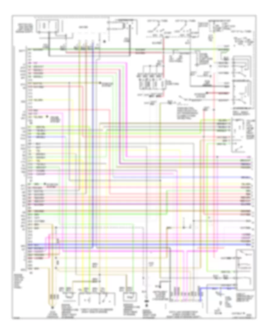
ENGINE PERFORMANCE
2.4L
2.4L, Engine Performance Wiring Diagrams, A/T (1 of 2) for Toyota 4Runner SR5 1995
List of elements for 2.4L, Engine Performance Wiring Diagrams, A/T (1 of 2) for Toyota 4Runner SR5 1995:
- #10
- #20
- (left
- (left kick panel)
- (right
- (right side of engine)
- (tachometer)
- 4wd
- 4wd a/t
- A10
- A11
- A12
- A13
- A14
- A15
- A16
- A17
- A18
- A19
- A20
- A21
- A22
- A3 j/b 1 kick panel)
- Acc
- Alt fuse 100a
- Batt
- C10
- C11
- C12
- C13
- C14
- C15
- C16
- Circuit opening relay (behind right side of i/p)
- Cluster system
- Coil wire
- Cruise control system
- Data link connector #1 (check connector) (right side of engine compt.)
- Distributor
- E10
- E11
- E12
- E13
- E14
- E15
- E16
- E17
- E18
- E19
- E20
- E21
- E22
- E23
- E24
- E25
- E26
- Efi fuse 15a
- Efi main relay
- Egr gas temperature sensor (right rear of engine)
- Engine control module (right kick panel)
- Engine coolant temperature sensor (right front of engine)
- Eo1
- Eo2
- Fpu
- Fuel injectors
- Fuel pump (in fuel tank)
- G100 (left fender)
- G120 (intake manifold)
- G200
- Hot at all times
- Hot in on or start
- Ht1
- Idl
- Ig2
- Igf
- Ign fuse 7.5a
- Igniter
- Ignition coil and igniter (left side of engine compt)
- Ignition switch
- Igt
- Instrument
- J/b 1 (left kick panel)
- Knk
- Knock sensor (right side of engine)
- Lock
- Noise filter (left side engine compt)
- Od1
- Od2
- Ox1
- Park/neutral position switch (on transmission) (closed in park or neutral)
- Pwr
- R/b 2 engine compt)
- Red
- Sp1
- Sp2
- St1
- Sta
- Start
- Starter relay
- Starting
- Starting system
- Stj
- Stp
- System
- Te2
- Tha
- Thg
- Throttle position sensor
- Thw
- Vcc
- Volume air flow meter (left front engine compt)
- Vta
2.4L, Engine Performance Wiring Diagrams, A/T (2 of 2) for Toyota 4Runner SR5 1995
List of elements for 2.4L, Engine Performance Wiring Diagrams, A/T (2 of 2) for Toyota 4Runner SR5 1995:
- (intake manifold)
- (left kick panel)
- (left side of engine)
- (on trans- mission)
- (right
- 4wd
- 4wd ind.
- A/t oil temp. ind.
- Add control relay (left side of i/p)
- Add detection switch (right side of engine compt.)
- B10
- B12
- Combination meter
- Cruise control system
- D12
- Diode
- Electronic controlled transmission pattern select switch
- Electronic controlled transmission solenoid (on transmission)
- Fuel pressure up vsv
- G120
- G200
- Gauge fuse 10a
- Hot at all times
- Hot in on or start
- Ht1
- Integration relay
- J/b 1 (left kick panel)
- Main heated oxygen sensor (bottom left of vehicle)
- Malf. ind. lamp
- O/d main switch (center console)
- O/d off ind.
- Of i/p)
- Oil temperature switch (right front of engine)
- Oxl1
- Pair vsv (left side of engine)
- Park/ neutral position switch n
- Power ind.
- Red
- Short pin (right side of engine compt.)
- Side
- Stop fuse 15a
- Stop light switch
- Transfer case indicator switch (on transfer case)
- Vehicle speed sensor
- W/ add
- W/o add
2.4L, Engine Performance Wiring Diagrams, M/T (1 of 2) for Toyota 4Runner SR5 1995
List of elements for 2.4L, Engine Performance Wiring Diagrams, M/T (1 of 2) for Toyota 4Runner SR5 1995:
- #10
- #20
- (left
- (left kick panel)
- (right
- (right side of engine)
- (tachometer)
- 4wd
- A3 j/b 1 kick panel)
- Acc
- Alt fuse 80a
- B10
- B11
- B12
- Batt
- Circuit opening relay (behind right side of i/p)
- Cluster system
- Coil wire
- D10
- D11
- D12
- D13
- D14
- D15
- D16
- D17
- D18
- D19
- D20
- D21
- D22
- D23
- D24
- D25
- D26
- Data link connector #1 (check connector) (right side of engine compt.)
- Distributor
- Efi fuse 15a
- Efi main relay
- Egr
- Egr gas temperature sensor (right rear of engine)
- Engine control module (right kick panel)
- Engine coolant temperature sensor (right front of engine)
- Eo1
- Eo2
- F10
- F11
- F12
- F13
- F14
- F15
- F16
- Fpu
- Fuel injectors
- Fuel pump (in fuel tank)
- G100 (left fender)
- G120 (intake manifold)
- G200
- Hot at all times
- Hot in on or start
- Ht1
- Ht2
- Idl
- Ig2
- Igf
- Ign fuse 7.5a
- Igniter
- Ignition coil & igniter (left side of engine compt)
- Ignition switch
- Igt
- Instrument
- J/b 1 (left kick panel)
- Knk
- Knock sensor (right side of engine)
- Lock
- Noise filter (left side engine compt)
- Nsw
- Ox1
- Ox2
- Pnk
- R/b 2 engine compt)
- Red
- Spd
- St1
- Sta
- Start
- Starter relay
- Starting
- Starting system
- Stj
- Stp
- System
- Te2
- Tha
- Thg
- Throttle position sensor
- Thw
- Vcc
- Volume air flow meter (left front engine compt)
- Vta
2.4L, Engine Performance Wiring Diagrams, M/T (2 of 2) for Toyota 4Runner SR5 1995
List of elements for 2.4L, Engine Performance Wiring Diagrams, M/T (2 of 2) for Toyota 4Runner SR5 1995:
-
- (intake manifold)
- (left kick panel)
- 4wd ind.
- Add control relay (behind left side of i/p)
- Add detection switch (right front of engine compt.)
- B12
- Combination meter
- D12
- Egr vsv (top of engine) (california)
- Fuel pressure up vsv (top of engine)
- G120
- G200
- Gauge fuse 10a
- Hot at all times
- Hot in on or start
- Ht1
- Ht2
- Integration relay
- J/b 1 (left kick panel)
- Main heated oxygen sensor (bottom left of vehicle)
- Malf. ind. lamp
- Oxl1
- Oxr1
- Pair vsv (left side of engine)
- Pnk
- Red
- Short pin (right front of of engine compt.)
- Stop fuse 15a
- Stop light switch
- Sub heated oxygen sensor (bottom left of engine) (california)
- Transfer case indicator switch (on transfer case)
- Vehicle speed sensor
- W/ add
- W/o add
3.0L
3.0L, Engine Performance Wiring Diagrams (1 of 2) for Toyota 4Runner SR5 1995
List of elements for 3.0L, Engine Performance Wiring Diagrams (1 of 2) for Toyota 4Runner SR5 1995:
- #10
- #20
- (left
- (left fender)
- (left front of engine)
- (left kick panel)
- (left side of engine compt)
- (right
- (tachometer)
- 2wd
- 4wd
- A/c
- A/t
- A10
- A11
- A12
- A13
- A14
- A15
- A16
- A17
- A18
- A19
- A20
- A21
- A22
- Acc
- Act
- Acv
- Air
- Air condit- ioning system
- Alt fuse 80a
- B10
- B11
- B12
- B13
- B14
- B15
- B16
- Batt
- C10
- C11
- C12
- C13
- C14
- C15
- C16
- C17
- C18
- C19
- C20
- C21
- C22
- C23
- C24
- C25
- C26
- Circuit opening relay (behind right side of i/p)
- Cluster system
- Coil
- Coil wire
- Conditioning
- Cruise control system
- Data link connector #1 (check connector) (right side of engine compt.)
- Distributor
- Efi fuse 15a
- Efi main relay
- Egr
- Egr gas temperature sensor (right side of engine)
- Engine control module (right kick panel)
- Engine coolant temperature sensor (center rear of engine)
- Eo1
- Eo2
- Fpu
- Fuel
- Fuel pump (in fuel tank)
- G100
- G117 (right rear cylinder head cover)
- G200
- Hot at all times
- Hot in on or start
- Ht1
- Ht2
- Idl
- Ig2
- Igf
- Ign fuse 7.5a
- Igniter
- Ignition
- Ignition switch
- Igt
- Injec-
- Instrument
- J/b 1
- J/b 1 (left kick panel)
- Kick panel)
- Knk
- Knock sensor (top center of engine)
- Lock
- M/t
- Noise filter (left front engine compt)
- Od1
- Od2
- Oil
- Ox1
- Ox2
- Park/neutral position switch (on transmission) (closed in park or neutral)
- Pnk
- Pwr
- R/b 2 engine compt)
- Red
- Sel1
- Sel2
- Sp1
- Sp2
- St1
- Sta
- Start
- Starter relay
- Starting
- Starting system
- Stj
- Stp
- System
- Te2
- Tha
- Thg
- Tho1
- Tho2
- Throttle position sensor (top center of engine)
- Thw
- Tors
- Volume air flow meter (left front engine compt)
- Vta
3.0L, Engine Performance Wiring Diagrams (2 of 2) for Toyota 4Runner SR5 1995
List of elements for 3.0L, Engine Performance Wiring Diagrams (2 of 2) for Toyota 4Runner SR5 1995:
- (a/t only)
- (a/t)
- (left kick panel)
- (m/t)
- (on trans- mission)
- (right side
- (right side of i/p)
- 4wd ind.
- 4wd w/ a/t
- 4wd w/ m/t
- A/t
- A/t oil temp. ind.
- A/t w/ 4wd only
- A/t w/ add
- Add control relay (left side of i/p)
- Add detection switch (left front of engine)
- B10
- B12
- Combination meter
- Compt)
- Cruise control system
- D12
- Diode
- Egr vsv
- Electronic controlled pattern select switch (a/t only)
- Electronic controlled transmission solenoid (on transmission)
- Fuel pressure up vsv
- G117 (right rear cylinder head cover)
- G200
- Gauge fuse 10a
- Hot at all times
- Hot in on or start
- Ht1
- Integration relay
- J/b 1 (left kick panel)
- M/t w/ add
- Main heated oxygen sensor (bottom left of vehicle)
- Malf. ind. lamp
- O/d main switch (center console)
- O/d off ind.
- Of engine
- Of engine compt)
- Oil temperature sensor (on transmission)
- Oxl1
- Oxr
- Pair vsv
- Park/ neutral position switch n
- Pnk
- Power ind.
- Red
- Short pin (left front of engine)
- Stop fuse 15a
- Stop light switch
- Sub heated oxygen sensor (bottom left of vehicle)
- Transfer case indicator switch (on transfer case)
- Transfer fluid temperature sensor (on transfer case)
- Transfer oil pressure switch (a/t: w/add) (on transfer case)
- Vehicle speed sensor
- W/ add
- W/o add
EXTERIOR LIGHTS
Back-up Lamps Wiring Diagram for Toyota 4Runner SR5 1995
List of elements for Back-up Lamps Wiring Diagram for Toyota 4Runner SR5 1995:
- (a/t)
- (m/t)
- A4 b2
- A8 b1
- B13
- Back-up light switch (on transmission)
- G904 (under left rear pillar)
- Gauge fuse 10a
- Hot in on and start
- Integration relay
- J/b 1 (behind left kick panel)
- Left back-up light
- Right back-up light
Exterior Lamps Wiring Diagram for Toyota 4Runner SR5 1995
List of elements for Exterior Lamps Wiring Diagram for Toyota 4Runner SR5 1995:
- (behind glove box) headlight auto cut out ecu
- (body harn, upper left quarter panel) b6
- (i/p harn, left side of radio) i6
- (i/p harn, right side of dash) i9
- (i/p harn,right end of dash) i13
- Alt fuse 100a
- B13
- C10
- C11
- C12
- Combination meter
- Combination switch
- G104 (front of left fender)
- G200 (left kick panel)
- G203 (right kick panel)
- G904 (under left rear pillar)
- G905 (under right rear pillar)
- Haz-horn fuse 15a
- Hazard switch
- Head
- High mount stop light
- Hot at all times
- Hot in on or start
- I11(usa) i12(can)
- I13 (i/p harn, right end of dash)
- I6 (i/p harn, left side of radio)
- I9(usa) i11(can) (i/p harn, upper right end of dash)
- I9(usa) i6(can)
- Integration relay
- J/b 1 (behind left kick panel)
- Left front parking light
- Left front turn signal light
- Left rear combination light
- Left turn
- License plate lights
- Light switch
- Off
- R/b 2 (right side of engine compartment)
- Red/
- Right front parking light
- Right front turn signal light
- Right rear combination light
- Right turn
- Stop
- Stop fuse 15a
- Stop light switch (on bracket above brake pedal)
- Tail
- Tail fuse 15a
- Taillight relay
- Turn
- Turn fuse 10a
- Turn signal flasher (behind left side of dash)
- Turn signal switch
- W/ auto cut ecu
- W/o auto cut ecu
- Warning lights system
GROUND DISTRIBUTION
Ground Distribution Wiring Diagram (1 of 3) for Toyota 4Runner SR5 1995
List of elements for Ground Distribution Wiring Diagram (1 of 3) for Toyota 4Runner SR5 1995:
- (beside r/b 2) r/b 4
- (i/p harness, behind left side of radio) i6 (can)
- (i/p harness, upper right end of dash) i11 (can)
- (i/p harness, upper right end of dash) i12 (can)
- (i/p harness, upper right side of dash i9 (can)
- (right kick panel) r/b 3
- (right side of engine compartment) r/b 2
- 2.4l
- 2wd a/t
- 3.0l
- 4wd a/t
- 4wd only
- A/c amplifier
- A/c condenser fan relay #1
- A/c condenser fan relay #2
- A/c switch
- A/c thermistor
- A17
- A18
- B10
- B11 (body harness, behind right rear comb light)
- Blower resistor
- C10
- C11
- C13
- C26
- Canada only
- Comb meter
- D13
- D24
- D26
- Data link connector 1
- Daytime running light relay
- Daytime running light resistor
- Dimmer switch
- E10 (engine harness, top right of engine)
- E12 (engine harness, top rear of engine)
- E13
- E14
- E25 (engine harness, top of engine)
- E26
- E3 (engine harness, front of engine compartment above grille opening)
- Efi main relay
- Except 4wd a/t
- Front heater relay
- G100 (front of left fender)
- G108 (left side of radiator)
- G117 (right rear of engine, on camshaft bearing cap)
- G120 (right side of engine, on intake manifold)
- G203 (right kick panel)
- G905 (under right rear pillar)
- Glove box light switch
- Heated oxygen sensor (main)
- Heater blower switch
- I10 (i/p harness, right side of dash)
- I11 (i/p harness, upper right end of dash)
- I11 (usa) (i/p harness, upper right end of dash)
- I15 (i/p harness, right kick panel)
- I16 (i/p harness, left kick panel)
- I3 (i/p harness, upper left side of dash)
- I6 (i/p harness, behind left side of radio)
- I6 (usa) (i/p harness, behind left side of radio
- I9 (i/p harness, upper right side of dash)
- I9 (usa) (i/p harness, upper right side of dash)
- Left front parking light
- Left front turn signal light
- Light control switch
- Main heated oxygen sensor
- Noise filter
- Of rear apron)
- Only
- Powertrain control module
- Rear heater
- Rear heater relay
- Rheostat
- Right front clearance light
- Right front turn signal light
- Right rear comb light
- Side of dash)
- Sub heated oxygen sensor
- To g904 (diagram 3 of 3)
- To starter relay (diagram 2 of 3)
- Volume air flow meter
Ground Distribution Wiring Diagram (2 of 3) for Toyota 4Runner SR5 1995
List of elements for Ground Distribution Wiring Diagram (2 of 3) for Toyota 4Runner SR5 1995:
- (i/p harness, behind left side of radio) i6 (can)
- (i/p harness, right end of dash) i3 (can)
- (i/p harness, upper right end of dash) i11 (can)
- (i/p harness, upper right end of dash) i3 (can)
- (i/p harness, upper right side of dash)
- (i/p harness, upper right side of dash) i9 (can)
- (motor)
- (vacuum)
- A/t
- A11
- A24
- Abs actuator
- Abs decel sensor
- Anti- lock ecu
- Anti- lock relay
- Auto antenna control relay
- B12
- Brake fluid level switch
- Cigarette lighter
- Circuit opening relay
- Clock
- Clutch start switch
- Comb meter
- Cruise control clutch switch
- Cruise control ecu
- Cruise control main relay
- Cruise control switch
- Daytime running light relay no. 4
- From a/c amplifier (diagram 1 of 3)
- Fuel sender
- G200 (left kick panel)
- I11 (i/p harness, upper right end of dash)
- I11 (usa) (i/p harness, upper right end of dash)
- I12 (can)
- I16 (i/p harness, left kick panel)
- I16 (usa) (i/p harness, left kick panel)
- I3 (i/p harness, right end of dash)
- I3 (usa) (i/p harness, right end of dash)
- I6 (i/p harness, behind left side of radio)
- I6 (usa) (i/p harness, behind left side of radio)
- I8 (i/p harness, upper right side of dash)
- I9 (can)
- I9 (i/p harness, upper right side of dash)
- I9 (usa) (i/p harness, upper right side of dash)
- Ignition key cylinder light
- Indicator switch
- Integration relay
- J/b 1 (left kick panel)
- Key interlock solenoid
- Left rear speaker
- M/t
- Moon roof relay
- O/d main switch
- Parking brake switch
- R/b 2 (right side engine compartment)
- Radio & player
- Right rear speaker
- Shift lock ecu
- Starter relay
- To fuel pump (diagram 3 of 3)
- Turn signal flasher
- Vacuum solenoid valve (2wd)
- Vacuum solenoid valve (4wd)
Ground Distribution Wiring Diagram (3 of 3) for Toyota 4Runner SR5 1995
List of elements for Ground Distribution Wiring Diagram (3 of 3) for Toyota 4Runner SR5 1995:
- (diagram 1 of 3)
- (i/p harness, behind left side of radio)
- (i/p harness, upper left side of dash)
- B13 (body harness, left side of liftgate)
- B3 (body harness, inside left front door)
- B5 (body harness, inside right front door)
- B6 (body harness, upper left quarter panel)
- Back door control switch
- Back door unlock warning switch
- Clutch start cancel switch
- Cruise control vacuum pump
- Cruise control vacuum switch
- Door control relay
- From cruise control c clutch switch (diagram 2 of 3)
- From splice i3 a
- Fuel pump
- G904 (under left rear pillar)
- High mount stop light
- I16 (can)
- I16 (i/p harness, left kick panel)
- I3 (can)
- I3 (i/p harness, upper left side of dash)
- I3 (usa) (i/p harness, upper left side of dash)
- I6 (can)
- I6 (usa) (i/p harness, behind left side of radio)
- I6 (usa) (i/p harness, left kick panel)
- Interior light (rear)
- Left back door lock detection switch
- Left back-up lamp
- Left door lock motor, door unlock detection switch, door key lock & unlock detection switch
- Left license plate light
- Left rear combination light
- Power window master switch & door lock control switch
- Rear power window and rear wiper control relay
- Rear power window limit switch
- Rear power window lock switch
- Rear window defogger
- Rear wiper motor
- Remote control mirror switch
- Right back door lock detection switch
- Right back-up lamp
- Right door lock control switch
- Right door lock motor, door unlock detection switch, door key lock & unlock detection switch
- Right license plate light
- Wiper/ washer switch
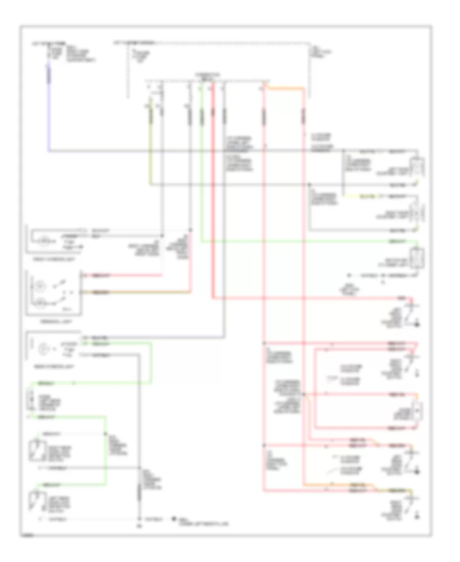
HEADLIGHTS
Headlight Wiring Diagram, with DRL for Toyota 4Runner SR5 1995
List of elements for Headlight Wiring Diagram, with DRL for Toyota 4Runner SR5 1995:
- Battery
- Brake fluid level switch (left rear of engine compt)
- Combination meter
- Combination switch
- Daytime running light relay (right side of i/p)
- Daytime running light relay 4 (left side of instrument cluster)
- Daytime running light resistor (left rear of engine compt)
- Dimmer relay (in r/b 2)
- Dimmer switch
- Dome fuse 15a
- Drl diode 1 (center of i/p)
- Drl diode 2 (center of i/p)
- Drl fuse 7.5a
- E1, e6 (3.0l) (eng harn, right front fender apron) (2.4l) (eng harn, behind left headlight)
- E1, e8 (3.0l) (eng harn, right front fender apron) (2.4l) (eng harn, left front fender apron)
- Exterior lights system
- Flash
- G100 (front of left fender)
- G200 (left kick panel)
- Gauge fuse 10a
- Head
- Headlight auto cut ecu (right side of i/p)
- Headlight relay (in r/b 2)
- High
- High beam indicator
- Hot at all times
- Hot in on or start
- I3 (i/p harn, upper left side of dash)
- I6 (i/p harn, behind left side of radio)
- I7 (i/p (harn, behind comb meter
- Instrument cluster system
- Integration relay
- Integration relay (in j/b 1)
- J/b 1 (left kick panel)
- Left front door courtesy switch
- Left headlight
- Left hi head fuse 10a
- Left lo head fuse 10a
- Light control switch
- Off
- Parking brake switch
- R/b 2 (right side of engine compt)
- Red
- Right headlight
- Right hi head fuse 10a
- Right lo head fuse 10a
- Starting/ charging system
- Tail
- W/ headlight auto cut ecu
- W/o headlight auto cut ecu
Headlight Wiring Diagram, without DRL for Toyota 4Runner SR5 1995
List of elements for Headlight Wiring Diagram, without DRL for Toyota 4Runner SR5 1995:
- Battery
- Combination switch
- Conbination meter
- Dimmer switch
- Dome fuse 15a
- E8 (eng harn, left fender apron)
- Exterior lights system
- Flash
- G200 (left kick panel)
- Gauge fuse 10a
- Head
- Headlight auto cut ecu (right side of i/p)
- Headlight relay (in r/b 2)
- High
- High beam indicator
- Hot at all times
- Hot in on or start
- I3 (i/p harn, upper left side of dash)
- I6 (i/p harn, behind left side of radio)
- I9 i6 (w/ auto cut ecu) (i/p harn, left end of dash) (w/o auto cut ecu) (i/p harn, behind left side of radio)
- Integration relay
- Integration relay (in j/b 1)
- J/b 1 (left kick panel)
- Left front door courtesy switch
- Left head fuse 10a
- Left headlight
- Light control switch
- Off
- R/b 2 (right side of engine compt)
- Red
- Right head fuse 10a
- Right headlight
- Tail
- W/ headlight auto cut ecu
- W/o headlight auto cut ecu
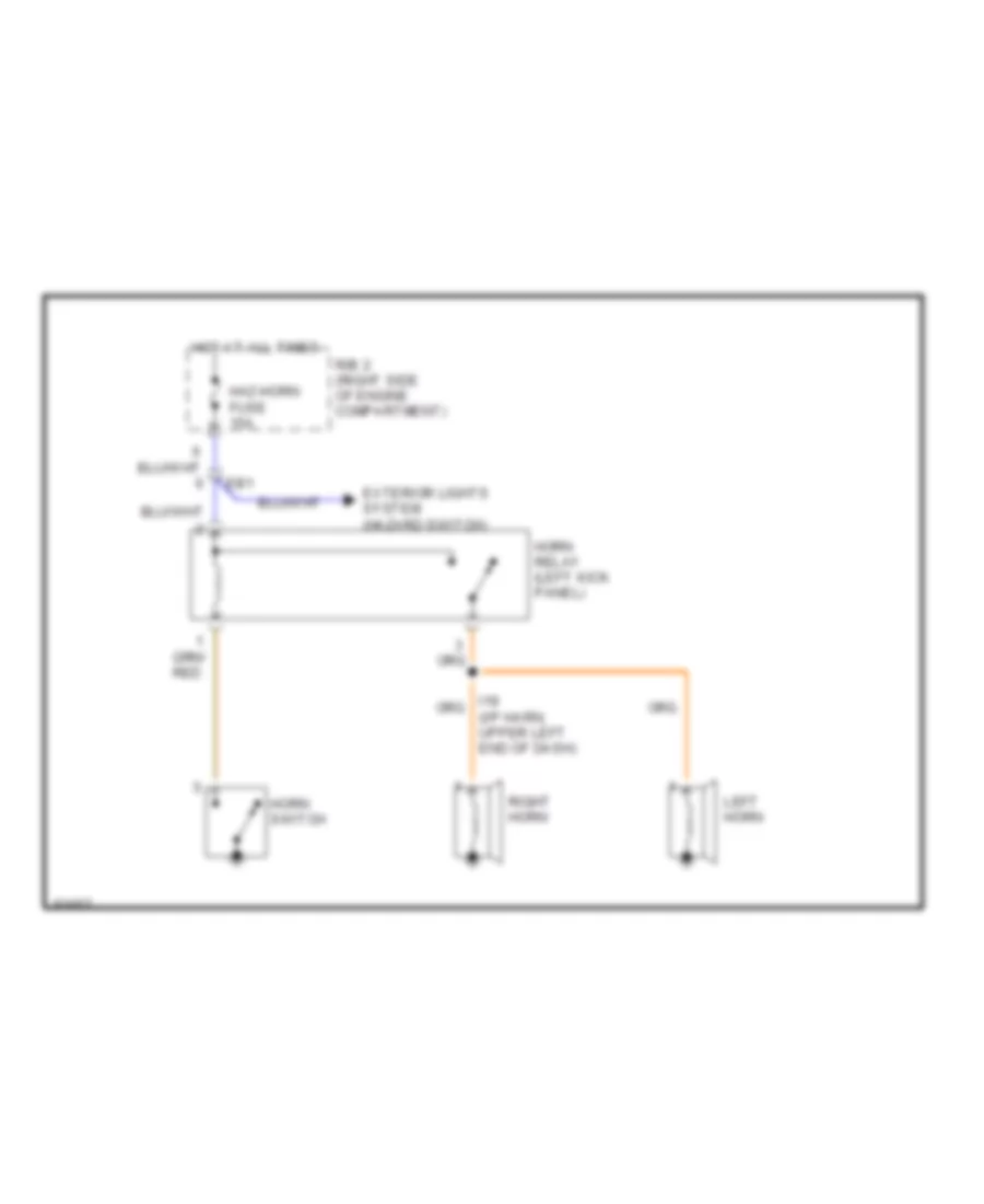
HORN
Horn Wiring Diagram for Toyota 4Runner SR5 1995
List of elements for Horn Wiring Diagram for Toyota 4Runner SR5 1995:
- Eb1
- Exterior lights system (hazard switch)
- Haz-horn fuse 15a
- Horn relay (left kick panel)
- Horn switch
- Hot at all times
- Left horn
- R/b 2 (right side of engine compartment)
- Right horn
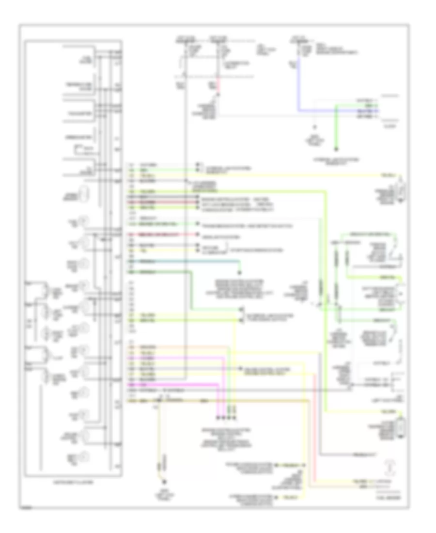
INSTRUMENT CLUSTER
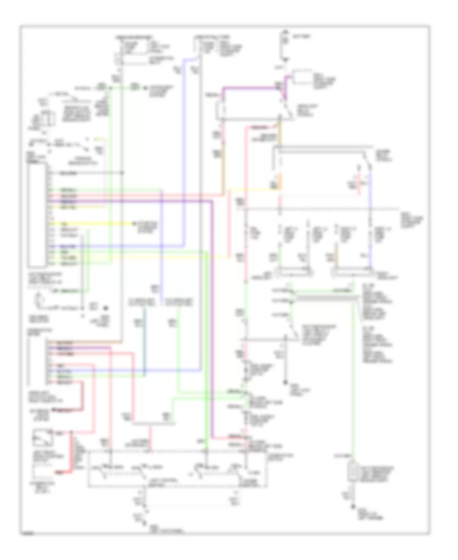
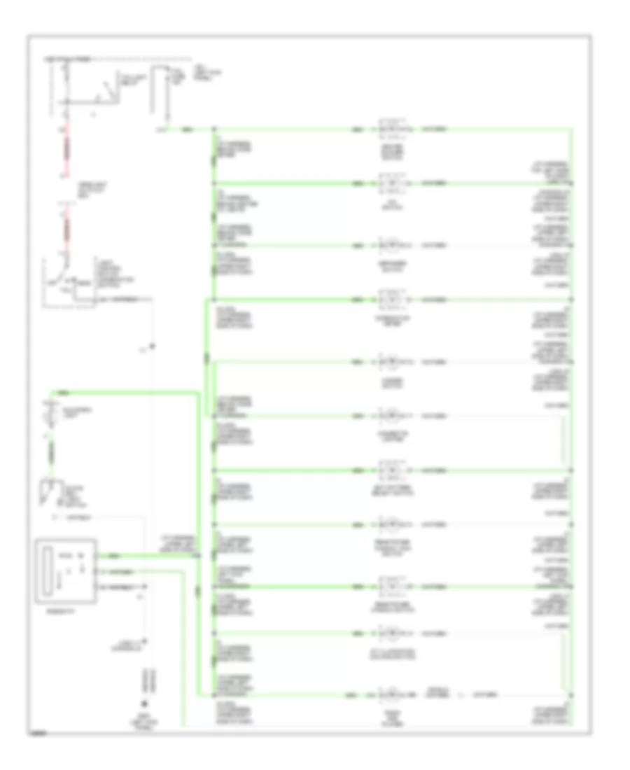
Instrument Cluster Wiring Diagram for Toyota 4Runner SR5 1995
List of elements for Instrument Cluster Wiring Diagram for Toyota 4Runner SR5 1995:
- (a/t)
- (abs ecu)
- (add detection switch)
- (canada)
- (i/p harness, behind combination meter)
- (i/p harness, upper right side of dash)
- (igniter)
- (integration relay)
- 4wd ind
- A/t fluid temp
- A10
- A11
- A12
- Abs ind
- Alternator
- Anti-lock brakes system
- B6 (body harness, upper left quarter panel)
- Back door ind
- Brake fluid level switch (brake fluid reservoir)
- Brake ind
- C10
- C11
- C12
- Canada
- Charge ind
- Check engine ind
- Cig fuse 15a
- Clock
- Cruise control ind
- Cruise control system (cruise control ecu)
- D10
- Daytime running light relay (behind center of dash) (canada)
- Dome fuse 15a
- Engine controls system
- Engine controls system (engine control ecu) (m/t) (engine and electronic controlled transmission ecu) (a/t)
- Engine controls system engine control ecu (m/t), engine and electronic controlled transmission ecu (a/t) and cruise control ecu
- Exterior lights system (turn signal switch)
- Fuel gauge
- Fuel ind
- Fuel sender
- G200 (left kick panel)
- Gauge fuse 10a
- Headlights system
- High beam ind
- Hot at all times
- Hot in on and acc
- Hot in on and start
- I16
- I7 (i/p harness, behind combination meter)
- I9 i6 (usa)
- Ign fuse
- Illum
- Instrument cluster
- Integration relay
- Interior lights system (rheostat)
- J/b 1 (left kick panel)
- Left turn ind
- O/d off ind
- Oil gauge
- Oil pressure sender (front of engine)
- Parking brake switch (left side of dash)
- Power windows system (back door unlock warning switch)
- Pwr ind
- R/b 2 (right side of engine compartment)
- Right turn ind
- Seat belt ind
- Speed sensor
- Speedometer
- Starting/charging system
- Tachometer
- Temperature gauge
- Transmissions system
- Usa
- Volt ind
- Warning system
- Water temperature sender (rear of engine)
- Wiper/washer system (back door unlock warning switch)
INTERIOR LIGHTS
Courtesy Lamps Wiring Diagram for Toyota 4Runner SR5 1995
List of elements for Courtesy Lamps Wiring Diagram for Toyota 4Runner SR5 1995:
- (i/p harness, upper left side of dash) i3 (canada)
- (i/p harness, upper right side of dash) (canada) i9
- (usa) i3 (i/p harness, upper left side of dash)
- B1 (body harness, above left front door)
- B15 (body harness, inside liftgate)
- B16 (body harness, inside liftgate)
- Diode (center of dash)
- Diode (left rear corner of vehicle)
- Dome fuse 15a
- Door
- Front interior light
- G200 (left kick panel)
- G904 (under left rear pillar)
- Gauge fuse 10a
- Hot at all times
- Hot in start or run
- I12 (i/p harness, upper right end of dash)
- I14 (i/p harness, right kick panel)
- I9 (i/p harness, upper right side of dash)
- I9 (usa) (i/p harness, upper right side of dash)
- Igntion key cylinder light
- Integration relay
- J/b 1 (left kick panel)
- Left door courtesy light
- Left front door courtesy switch
- Left rear door courtesy switch
- Left rear door lock detection switch
- Off
- Personal light
- R/b 2 (right side of engine compartment)
- Rear interior light
- Red
- Right door courtesy light
- Right front door courtesy switch
- Right rear door courtesy switch
- Right rear door lock detection switch
- W/ power windows
- W/o power windows
Instrument Illumination Wiring Diagram for Toyota 4Runner SR5 1995
List of elements for Instrument Illumination Wiring Diagram for Toyota 4Runner SR5 1995:
- (canada) i9 (i/p harness, upper right side of dash)
- (i/p harness, behind comb meter) i7 (canada)
- (i/p harness, left kick panel) (canada) i16
- (i/p harness, left kick panel) i16 (canada)
- (i/p harness, top left side of dash) (usa) i18
- (i/p harness, upper left side of dash) (canada) i3
- (i/p harness, upper left side of dash) i3
- (i/p harness, upper left side of dash) i3 (canada)
- (usa) i11 (canada) i6
- (usa) i3 (i/p harness, upper left side of dash)
- (usa) i9 (i/p harness, upper right side of dash)
- A/c switch
- A/t illuminatiom (o/d main switch)
- A10
- C14
- Cigarette lighter
- Combination meter
- Defogger switch
- Ect pattern select switch
- G200 (left kick panel)
- Glove box light
- Glove box light switch
- Hazard switch
- Head
- Headlight auto cut ecu
- Heater blower switch
- Hot at all times
- I11
- I18 (i/p harness, behind center a/c vents)
- I3 (i/p harness, upper left side of dash)
- I8 (i/p harness, upper right side of dash)
- I9 (i/p harness, upper right side of dash)
- I9 (usa) (i/p harness, upper right side of dash)
- J/b 1 (left kick panel)
- Light control switch (combination switch)
- Off
- Radio and player
- Rear power window lock switch
- Rear power window switch
- Rheostat
- Side of dash)
- Tail
- Tail fuse 15a
- Taillight relay
POWER ANTENNA
Power Antenna Wiring Diagram for Toyota 4Runner SR5 1995
List of elements for Power Antenna Wiring Diagram for Toyota 4Runner SR5 1995:
- (canada)
- (i/p harn, upper left side of dash) i3
- (i/p harn, upper right side of dash) i9
- (usa)
- Auto antenna control relay (behind left side of dash)
- Auto antenna motor (right front fender inner panel)
- Dome fuse 15a
- Down
- G200 (left kick panel)
- Gauge fuse 10a
- Hot at all times
- Hot in acc or on
- Hot in on or start
- Integration relay
- J/b 1 (left kick panel)
- Off
- On player switch
- R/b 2 (right side of eng compt)
- Radio & player
- Radio fuse 7.5a
- Radio sw
- Solid state
POWER DISTRIBUTION
Power Distribution Wiring Diagram (1 of 2) for Toyota 4Runner SR5 1995
List of elements for Power Distribution Wiring Diagram (1 of 2) for Toyota 4Runner SR5 1995:
- (right side of engine compartment)
- (right side of engine compartment) r/b 2
- 22r-e: 2.2l
- 3vz-e: 3.0l
- A/c switch, back-up lights, license plate lights, cigarette lighter, clock combination meter, defogger switch, electrically controlled transmission pattern select switch, front parking lights, glove box light, glove box light switch, hazard switch, heater blower switch, integration relay, light reminder relay, o/d main switch, radio & player, rheostat, taillights rear power window lock switch, rear power window switch
- Abs (4wd) fuse 60a
- Abs ecu, cruise control ecu, ecm & engine ecu, high mounted stop light, stop lights, shift lock ecu, stop light switch
- Abs relay, abs actuator, abs ecu
- Alt fuse 100a (a/t) 80a (m/t)
- Am1 fuse 40a
- Am2 fuse 30a
- Auto antenna motor, auto antenna, control relay, abs ecu, right back door lock detection switch, left back door lock detection switch, clock, cruise control ecu, diode (for power window), door control relay, left front door courtesy switch right front door courtesy switch, diode (for rear interior light), left door courtesy light, right door courtesy light, left rear door courtesy switch, right rear door courtesy switch, headligh auto cut ecu, ignition switch, unlock warning switch, integration relay, front interior light, rear interior light, map light, radio & player, rh speaker, lh speaker
- Battery
- C14
- Canada
- Circuit opening relay, data link connector 1, engine control module, fuel pump, heated oxygen sensor (main), heated oxygen sensor (sub), volume air flow meter, vsv (for pair), vsv (for egr), vsv (for fpu), efi main relay
- Dimmer relay
- Dimmer switch, light control switch, drl relay (main), drl relay no.4, diode no.1, diode no.2
- Dome fuse 15a
- Drl fuse (can) 7.5a
- Drl resistor, drl relay no.4, left headlight
- Drl resistor, drl relay no.4, right headlight
- E1 (engine harness, right front of fender apron)
- Efi fuse 15a
- Fuse block
- Haz-horn fuse 15a
- Headlight relay
- High beam indicator light, dimmer switch, left headlight,
- High beam indicator light, dimmer switch, right headlight,
- Horn switch, left front turn signal light, right front turn signal light, right horn, left horn, hazard switch, horn relay, left rear turn signal light, right rear turn signal light
- Integration relay
- Left head fuse 10a
- Left turn signal indicator light, right turn signal indicator light, drl resistor, drl relay no.4, right headlight
- Left-hi head fuse 10a
- Left-lo head fuse 10a
- R/b 2
- Right head fuse 10a
- Right-hi head fuse 10a
- Right-lo head fuse 10a
- Stop fuse 15a
- Tail fuse 15a
- Taillight relay
- To cassette r/b, power fuse (diagram 2 of 2)
- To ignition switch (diagram 2 of 2)
- To r/b 4 (diagram 2 of 2)
- Usa
Power Distribution Wiring Diagram (2 of 2) for Toyota 4Runner SR5 1995
List of elements for Power Distribution Wiring Diagram (2 of 2) for Toyota 4Runner SR5 1995:
- (beside r/b 2)
- (i/p harness, behind left side of radio) i6 (can) i3 (usa) (i/p harness, upper left side of dash)
- (i/p harness, behind left side of radio) i6 (usa)
- (i/p harness, behind left side of radio) i6 (usa) i3 (can) (i/p harness, upper left side of dash)
- (left kick panel)
- A/c amplifier, a/c cut relay, a/c thermistor, a/c pressure switches, a/c switch, water temp switch
- A/c condenser fan motor, radio & player, a/c condenser fan relay no.1, a/c condenser fan relay no.2
- A/c fuse 10a
- Abs actuator, abs relay, abs ecu,
- Abs deceleration sensor, abs ecu
- Acc
- Add indicator switch, abs actuator, abs check connector, abs relay, add control relay, abs deceleration sensor, abs ecu, auto antenna control relay, back-up light switch, brake fluid level switch, back door unlock warning switch, left back-up & license plate light, right back-up & license plate light, defogger relay, moon roof relay, abs warning light, a/t oil temp indicator light, a/t parking indicator light, back door unlock indicator light, combination meter, malfunction indicator lamp, o/d off indicator lamp, rear anti-lock warning light, cruise control indicator light, seat belt warning light, 4wd indicator light, cruise control ecu, data link connector 1, daytime running light relay (main),
- Auto antenna control relay, light reminder relay, radio & player, left remote control mirror, right remote control mirror, remote control mirror switch
- Blower motor, blower resistor, heater blower switch, front heater relay
- Cassette r/b
- Cds fuse 30a
- Cig fuse 15a
- Cigarete lighter, clock, shift lcok ecu
- Cigarette lighter
- Cruise control switch, cruise control ecu, cruise control main relay, generator,
- Defog fuse 20a
- Defogger switch
- Defogger switch,
- Diode (for add), door control relay, diode (for rear window defogger) electronically controlled transmission pattern select switch, engine control module, fuel sender, heat blower switch, headlight auto cut ecu, transfer oil pressure switch, integration relay, light reminder relay, oil pressure switch, oil temperature switch, o/d main switch, park/neutral position switch, parking brake switch, rear heater, rear power window relay, rear wiper control relay, rear power window limit switch, shift lock ecu, transfer neutral position switch, vsv (for 2wd, add), vsv (for 4wd, add), water temp senser, front heater relay, rear heater relay
- Ecu-ig fuse 20a
- Engine fuse 10a
- From r/b 2, alt fuse (diagram 1 of 2)
- From r/b 2, am1 fuse (diagram 1 of 2)
- From r/b 2, am2 fuse (diagram 1 of 2)
- Front heater relay
- Fuse block
- G200
- Gauge fuse 10a
- Generator, efi main relay
- Heater fuse 20a
- Heater fuse 40a
- I12 (i/p harness, upper right end of dash)
- I3 (can) (i/p harness, upper left side of dash)
- I7 (i/p harness, upper left quarter panel)
- Ign fuse 7.5a
- Ignition switch
- Integration relay
- J/b 1 (left kick panel)
- Kick panel)
- Left turn signal indicator light, right turn signal indicator light, turn signal switch, left front turn signal light, right front turn signal light, hazard switch, integration relay, left rear turn signal light, right rear turn signal light, turn signal flasher
- Lock
- Moon roof relay, door control relay, right door lock motor, right door unlock detention switch, right door key lock & unlock detection switch, left door lock motor, left door unlock detention switch, left door key lock & unlock detection switch, left rear door lock motor, right rear door lock motor, moon roof control switch, moon roof motor, power window control switches, door lock control switch, power window motors, rear power window relay, rear wiper control relay, rear wiper motor
- Power fuse 30a
- R/b 3 (right
- R/b 4
- Radio fuse 7.5a
- Rear anti lock fuse 15a
- Rear heater, rear heater relay
- Rear window defogger
- Red
- Start
- Turn fuse 10a
- Wiper & washer switch rear power window relay, rear wiper control relay, washer motor, wiper motor
- Wiper fuse 20a
POWER DOOR LOCKS
Power Door Lock Wiring Diagram for Toyota 4Runner SR5 1995
List of elements for Power Door Lock Wiring Diagram for Toyota 4Runner SR5 1995:
- (i/p harn, right side of dash) i13 (usa) i11 (canada)
- (usa- i/p harn, right side of dash) (canada- i/p harn, left side of dash) i9 (usa) i3 (canada)
- B3 (body harn, in left front door)
- B5 (body harn, in right front door)
- Cassette r/b (left kick panel)
- Dome fuse 15a
- Door lock control relay (left side of i/p)
- G200 (left kick panel)
- Hot at all times
- I13 (i/p harn, right end of dash)
- I9 (i/p harn, right side of dash)
- I9 (usa) i3 (canada) (usa- i/p harn, right side of dash) (canada- i/p harn, left side of dash)
- Left door courtesy switch
- Left door key lock/unlock switch
- Left door lock control switch
- Left door lock motor and unlock detection switch
- Left rear door lock motor
- Lock
- Lock timer
- Power fuse 30a
- R/b 2 (right side of engine compartment)
- Red
- Right door courtesy switch
- Right door key lock/unlock switch
- Right door lock control switch
- Right door lock motor and unlock detection switch
- Right rear door lock motor
- Solid state
- Unlock
- Unlock timer
- Unlock warning switch (ignition switch)
POWER MIRRORS
Power Mirror Wiring Diagram for Toyota 4Runner SR5 1995
List of elements for Power Mirror Wiring Diagram for Toyota 4Runner SR5 1995:
- B5 (body harness, (inside right front door)
- Down
- Down right
- G200 (left kick panel)
- Hot in acc or on
- J/b 1 (left kick panel)
- Left
- Left remote control mirror
- Operation switch
- Pnk
- Radio fuse 7.5a
- Remote control mirror switch
- Right
- Right remote control mirror
- Select switch
- Up left
POWER TOP/SUNROOF
Power Top/Sunroof Wiring Diagrams for Toyota 4Runner SR5 1995
List of elements for Power Top/Sunroof Wiring Diagrams for Toyota 4Runner SR5 1995:
- Cassette relay block (left kick panel)
- Close
- Door control relay (behind left side of i/p)
- G200 (left kick panel)
- Gauge fuse 10a
- Hot at all times
- Hot in on or start
- Integration relay
- J/b 1 (left kick panel)
- Left front door courtesy switch (in left "a" pillar)
- Moon roof control switch
- Moon roof motor (front of roof)
- Moon roof relay (in cassette relay block) (left kick panel)
- Open
- Power fuse 30a
- Red
- Right front door courtesy switch (in right "a" pillar)
- Solid state
- W/ power windows
- W/o power windows
- W/power windows
POWER WINDOWS
Power Window Wiring Diagram, Front for Toyota 4Runner SR5 1995
List of elements for Power Window Wiring Diagram, Front for Toyota 4Runner SR5 1995:
- (canada)
- (i/p haren, upper left side of i/p) i3
- (i/p harn, upper left side of i/p) i3 (i/p harn, upper right side of i/p) i9
- (usa)
- B3 (body harn, inside left front door)
- Cassette relay block (left kick panel)
- Door control relay (behind left side of i/p)
- Down
- Driver's
- G200 (left kick panel)
- Gauge fuse 10a
- Hot at all times
- Hot in on or start
- I13 (right end of i/p)
- I3 i6
- I9 (i/p harn, upper right side of i/p) i3 (i/p harn, upper left side of i/p)
- Integration relay
- J/b 1 (left kick panel)
- Left front door courtesy switch (at base of left "a" pillar)
- Left front power window motor
- Left rear
- Left rear power window control switch
- Left rear power window motor
- Lock
- Normal
- Passenger's
- Power fuse 30a
- Power window master switch
- Rear power window circuit (diode)
- Red
- Right front door courtesy switch (at base of right "a" pillar)
- Right front power window control switch
- Right front power window motor
- Right rear
- Right rear power window control switch
- Right rear power window motor
- Solid state
Power Window Wiring Diagram, Rear for Toyota 4Runner SR5 1995
List of elements for Power Window Wiring Diagram, Rear for Toyota 4Runner SR5 1995:
- B13
- B15 (body harn, inside liftgate)
- B16 (body harn, inside liftgate)
- B6 (body harn, upper left quarter panel)
- Back door
- Back door control switch
- Back door unlock warning switch (center of rear door)
- C16
- Cassette relay block (left kick panel)
- Combination meter
- Diode
- Down
- Front power windows circuit (power window master switch & right front control switch)
- G200 (left kick panel)
- G904 (under left rear pillar)
- Gauge fuse 10a
- Hot at all times
- Hot in on or start
- I16
- Integration relay
- J/b 1 (left kick panel)
- Left back door detection switch (left side of rear door)
- Power fuse 30a
- Rear power limit switch (center of rear door)
- Rear power window & rear wiper control relay (left rear side of cargo area, behind trim panel)
- Rear power window lock switch (in left rear door)
- Rear power window motor (center of rear door above window)
- Rear power window switch
- Red
- Right back door detection switch (right side of rear door)
- Solid state
- W/ front power windows
- W/o front power windows
- Wiper fuse 20a
RADIO
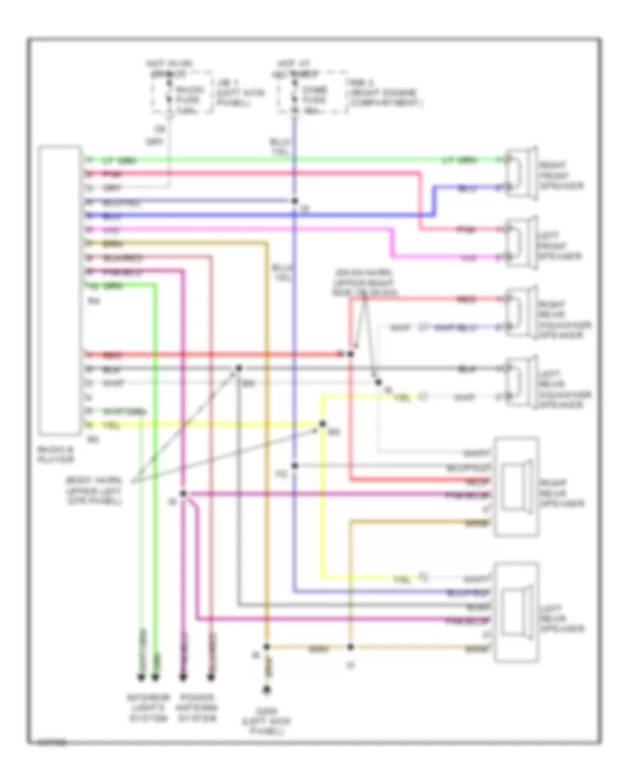
Radio Wiring Diagrams for Toyota 4Runner SR5 1995
List of elements for Radio Wiring Diagrams for Toyota 4Runner SR5 1995:
- (body harn, upper left qtr panel)
- (dash harn, upper right side of dash)
- Dome fuse 15a
- G200 (left kick panel)
- Hot at all times
- Hot in on or acc
- I12
- Interior lights system
- J/b 1 (left kick panel)
- Left front speaker
- Left rear speaker
- Left rear squawker speaker
- Pnk
- Power antenna system
- R/b 2 (right engine compartment)
- Radio & player
- Radio fuse 7.5a
- Red
- Red
- Right front speaker
- Right rear speaker
- Right rear squawker speaker
SHIFT INTERLOCKS
Shift Interlock Wiring Diagram for Toyota 4Runner SR5 1995
List of elements for Shift Interlock Wiring Diagram for Toyota 4Runner SR5 1995:
- Cig fuse 15a
- Exterior lights system (stop lights)
- G200 (left kick panel)
- Gauge fuse 10a
- Hot at all times
- Hot in acc or on
- Hot in on or start
- I11 (i/p harn, upper right end of dash)
- Integration relay
- J/b 1 (left kick panel)
- Key interlock solenoid (on steering column)
- Shift lock control switch
- Shift lock ecu (below front console)
- Shift lock solenoid
- Sls+
- Sls-
- Stop fuse 15a
- Stop light switch (on bracket, above brake pedal)
STARTING/CHARGING
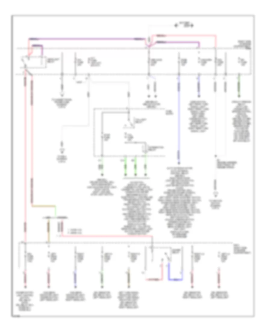
Charging Wiring Diagram for Toyota 4Runner SR5 1995
List of elements for Charging Wiring Diagram for Toyota 4Runner SR5 1995:
- 2.4l w/ a/t
- Alt fuse 80a 100a
- Am1 fuse 40a
- Battery
- Battery ground
- Charge warning light
- Comb- ination meter
- Daytime runn- ing light relay main (canada) (behind right side of dash)
- Engine fuse 10a
- Except 2.4l w/ a/t
- Generator
- Hot in on or start
- I9 (i/p harness, behind center of a/c vents)
- Ign fuse 7.5a
- J/b 1 (on left kick panel)
- Nca
- R/b 2 (on right side of engine compt)
- Red
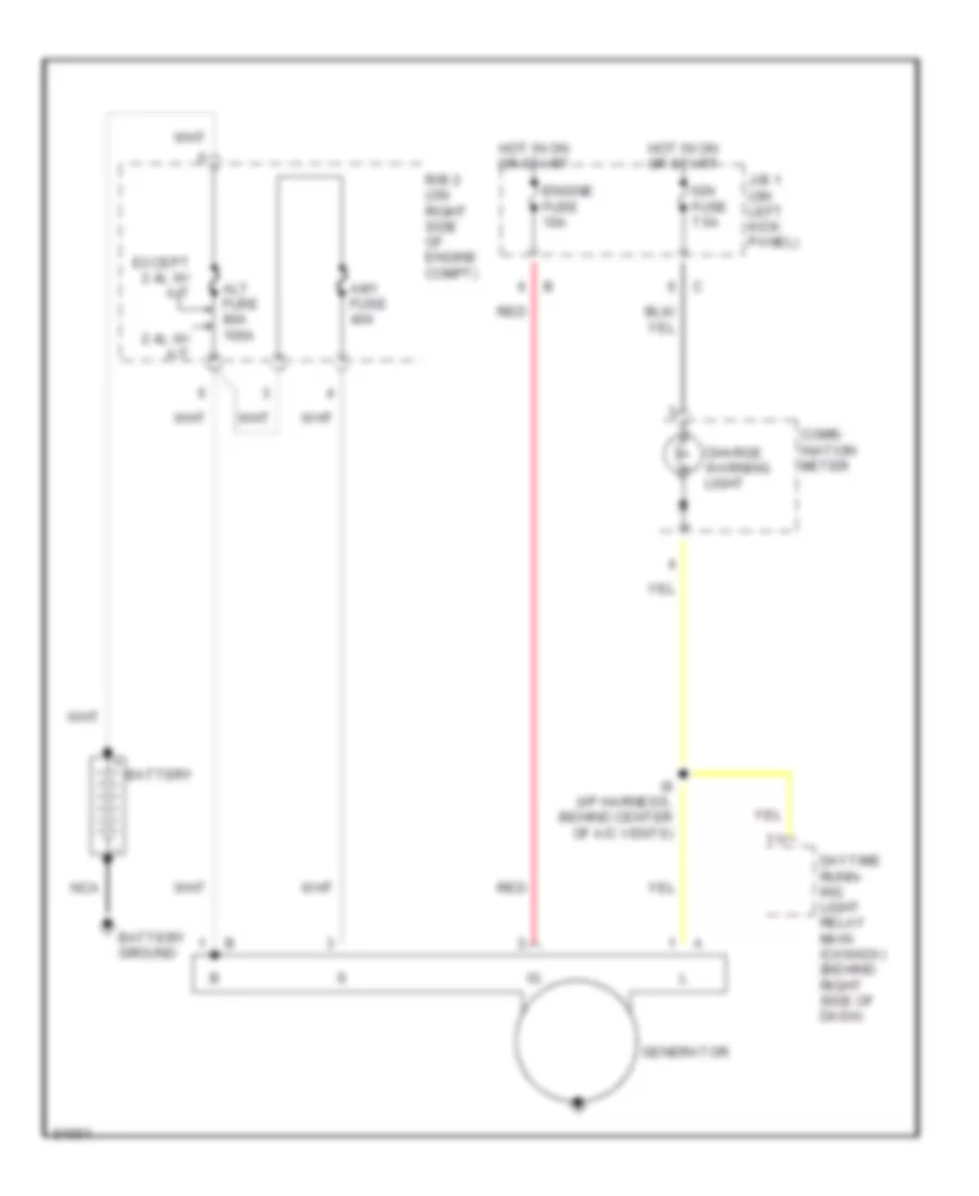
Starting Wiring Diagram for Toyota 4Runner SR5 1995
List of elements for Starting Wiring Diagram for Toyota 4Runner SR5 1995:
- (2.4l)
- (3.0l)
- (3.0l) (engine harness, top right side of engine)
- (ex 2.4l a/t) (2.4l a/t)
- (on top right rear of engine) cold start injector
- (right kick panel, i/p harness) (3.0l) i15
- (right kick panel, i/p harness) (3.ol) i15
- (right kick panel, i/p harness) i14 (canada)
- (right kick panel, i/p harness) i15
- A/t
- A/t only
- Acc
- Alt fuse 80a 100a
- Am1 fuse 40a
- Am2 fuse 30a
- Battery
- Battery ground
- Circuit opening relay
- Clutch start cancel switch (m/t)
- Clutch start switch (m/t) (above clutch pedal)
- E11 (2.4) (engine harness, right front strut tower)
- E4 e11 (2.4) (engine harness, right front strut tower)
- Engine control module (engine and electronically controlled transmission ecu) (on right kick panel)
- Engine control module (engine ecu) (on right kick panel)
- G200 (left kick panel)
- I12 (usa) (i/p harn- ness, upper right end of dash)
- I15 (i/p harness, right kick panel)
- I16 (usa) i20 (cana- da) (i/p harness, left kick panel)
- Ignition switch
- M/t
- M/t only
- Nca
- Off
- P/ n
- Park/ neutral position switch (on trans- mission)
- R/b 2 (right side of engine compt)
- Sta
- Start
- Start injector time switch (2.4l: on right side of engine; 3.0l: on top rear of engine)
- Starter
- Starter relay
- Stj
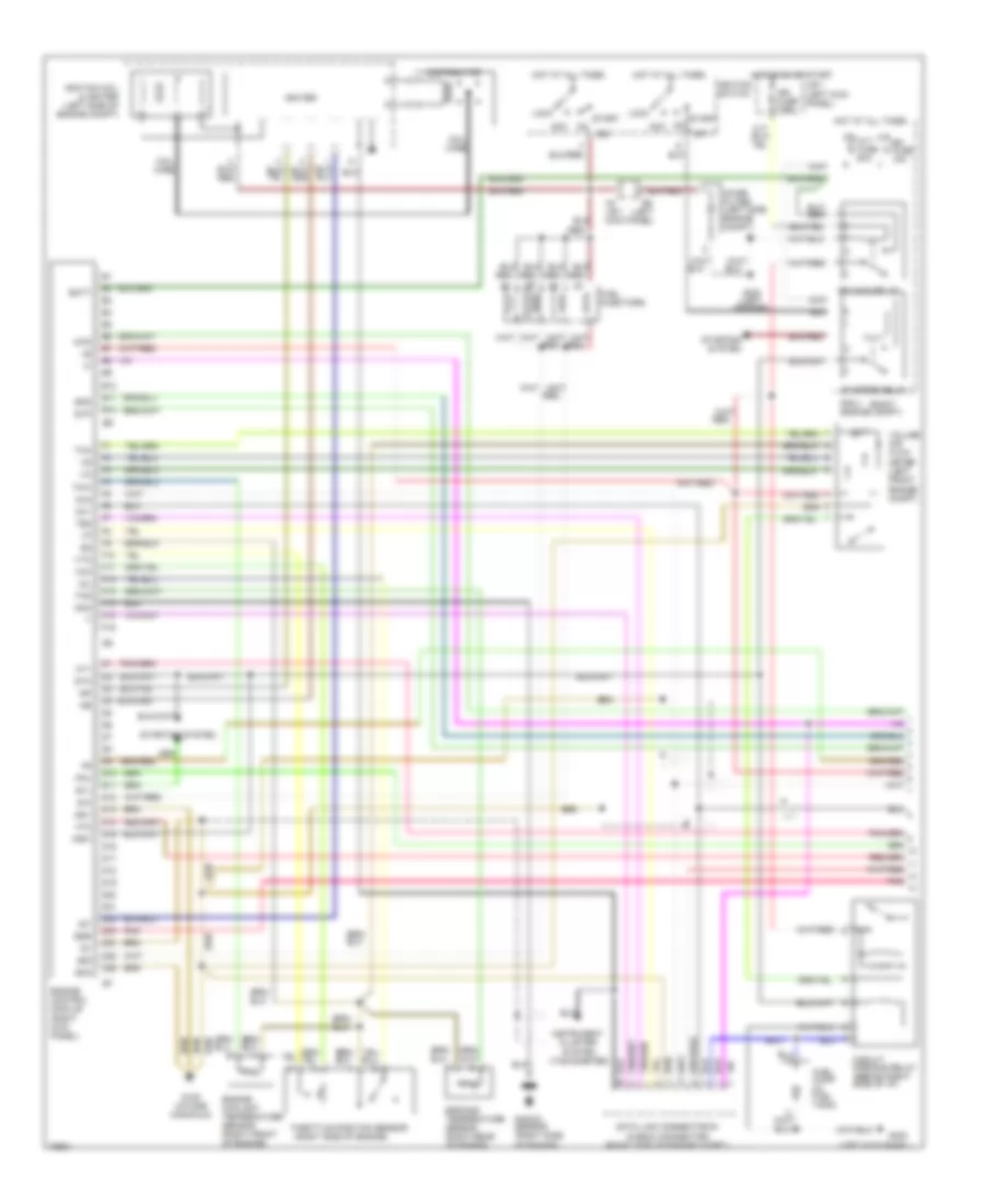
TRANSMISSION
2.4L
2.4L, Transfer Case Wiring Diagram, A/T for Toyota 4Runner SR5 1995
List of elements for 2.4L, Transfer Case Wiring Diagram, A/T for Toyota 4Runner SR5 1995:
- (eng harn, right strut tower)
- (i/p harn, right end dash) i11
- (i/p harn, right kick panel)
- (i/p harn, right kick panel) i14
- (i/p harn, upper right dash)
- (right kick panel) diode d7
- (right side eng compt) (2wd add) vsv
- (right side eng compt) (4wd add) vsv
- (transfer case) transfer oil press sw
- 1995 vftc c
- 4wd
- 4wd indic.
- A/t parking indic.
- A10
- A12
- Add
- Add control relay (behind left side of dash)
- Add detection switch (front differential)
- E11
- E12
- Engine and electronic controlled transmission ecu (right kick panel)
- G200 (left kick panel)
- Gauge fuse 10a
- Hot in on or start
- I11 usa can
- I15
- Indicator switch (for transfer position) (transfer case)
- Instrument cluster
- Integration relay
- J/b 1 (left kick panel)
- Of engine compt)
- Park/neutral position switch (right side of transmission)
- Red
- Short pin (right side
- Transfer neutral position switch (on transfer case)
- W/ add
- W/o
Transfer Case Wiring Diagram, M/T for Toyota 4Runner SR5 1995
List of elements for Transfer Case Wiring Diagram, M/T for Toyota 4Runner SR5 1995:
- (i/p harn, upper right side of dash)
- 2.4l
- 3.0l
- 4wd
- 4wd indic.
- A12
- Add control relay (left side of dash)
- Add detection switch (front differential)
- C 1995 vftc
- Engine control module (right kick panel)
- G200 (left kick panel)
- Gauge fuse 10a
- Hot in on or start
- I11 (usa) i12 (canada)
- I11 (usa) i14 (canada)
- I15 (3.0l) e12 (2.4l) (eng harn, (i/p harn, right kick panel)
- I15 (i/p harn, right kick panel)
- I9 (i/p harn, upper right side of dash)
- Indicator switch (transfer position) (on transfer case)
- Instrument cluster
- Integration relay
- J/b 1 (left kick panel)
- Red
- Short pin (2.4l right side eng compt) (3.0l left front eng compt)
- Top right of eng)
- Vsv (2wd add) (right side eng compt)
- Vsv (4wd add) (right side eng compt)
- W/ add
- W/o add
Transmission Wiring Diagram for Toyota 4Runner SR5 1995
List of elements for Transmission Wiring Diagram for Toyota 4Runner SR5 1995:
- (4wd)
- (a/t)
- (behind comb meter)
- (left side of engine compt)
- (left side of firewall)
- (m/t)
- (right end of dash) i11
- (right kick panel)
- (right side of dash)
- (top right of engine) e12
- * **
- * w/ 2.4l
- ** *
- ** w/ 3.0l v6 engine
- +b1
- 2wd
- 4wd
- Add
- Add detection switch (on add actuator, on front of differential)
- Batt
- C17
- Cruise control system
- Data link connector 1 (right side eng compt)
- Dg te2 t e1
- E12
- E15 *
- E21
- E23
- E4 (right side of engine) e4
- E4 (top right of engine)
- Efi fuse 15a
- Efi main
- Electronic controlled transmission pattern select switch
- Electronic controlled transmission solenoid and vehicle speed sensor
- Engine
- Engine and electronic controlled transmission ecu (right kick panel)
- Engine controls system
- Engine coolant temperature sensor (on intake manifold)
- Exterior lights system
- G100 (front of left front fender)
- G117 (cam bearing cap)
- G120 (intake manifold)
- Gauge fuse 10a
- Hot at all times
- Hot in on or start
- I15
- I5 left side i/p) **
- I8 (right side of dash)
- Idl
- Ign fuse 7.5a
- Indicator switch (transfer position)
- Indicator switch (transfer position) (on t-case)
- Instrument cluster system
- Integration relay
- Interior lights system
- J/b 1 (left kick panel)
- N **
- Nca
- No. 1
- No. 2
- No. 3
- No. 4
- Norm
- O/d main switch
- Od1
- Od2
- Oil
- Oil temperature sensor (right front trans pan)
- Oil temperature switch (right side eng compt)
- Park/neutral position switch (right side of transmission)
- Pin a12
- Pin b6
- Pin c7
- Pin d2
- Pin d4
- Pwr
- R/b 2 (right eng compt)
- Red
- Relay
- Short pin
- Sp1
- Sp2
- Sta
- Starting/ charging system
- Stop fuse 15a
- Stop light switch (above brake pedal)
- Stp
- Te2
- Te2 th02
- Th01
- Throttle position sensor (on throttle body)
- Thw
- Transfer case
- Transfer fluid temperature sensor
- Transfer oil pressure switch (for add)
- Transmissions systems (a/t transfer case circuit)
- Vcc
- Vehicle speed sensor
- Vta
- W/ add
- W/o
3.0L
3.0L, Transfer Case Wiring Diagram, A/T for Toyota 4Runner SR5 1995
List of elements for 3.0L, Transfer Case Wiring Diagram, A/T for Toyota 4Runner SR5 1995:
- (i/p harn, right end dash) i11
- (i/p harn, right kick panel) i14
- (i/p harn, upper right dash)
- (right kick panel) diode d7
- (right side eng compt) (2wd add) vsv
- (right side eng compt) (4wd add) vsv
- (transfer case) transfer oil press sw
- 1995 vftc c
- 4wd
- 4wd indic.
- A12
- Add
- Add control relay (behind left side of dash)
- Add detection switch (front differential)
- Can
- Engine and electronic controlled transmission ecu (right kick panel)
- G200 (left kick panel)
- Gauge fuse 10a
- Hot in on or start
- I11 usa
- I11 usa can
- I15
- I15 (i/p harn, right kick panel)
- Indicator switch (for transfer position) (transfer case)
- Instrument cluster
- Integration relay
- J/b 1 (left kick panel)
- Short pin (left front of engine compt)
- W/ add
- W/o
Transfer Case Wiring Diagram, M/T for Toyota 4Runner SR5 1995
List of elements for Transfer Case Wiring Diagram, M/T for Toyota 4Runner SR5 1995:
- (i/p harn, upper right side of dash)
- 2.4l
- 3.0l
- 4wd
- 4wd indic.
- A12
- Add control relay (left side of dash)
- Add detection switch (front differential)
- C 1995 vftc
- Engine control module (right kick panel)
- G200 (left kick panel)
- Gauge fuse 10a
- Hot in on or start
- I11 (usa) i12 (canada)
- I11 (usa) i14 (canada)
- I15 (3.0l) e12 (2.4l) (eng harn, (i/p harn, right kick panel)
- I15 (i/p harn, right kick panel)
- I9 (i/p harn, upper right side of dash)
- Indicator switch (transfer position) (on transfer case)
- Instrument cluster
- Integration relay
- J/b 1 (left kick panel)
- Red
- Short pin (2.4l right side eng compt) (3.0l left front eng compt)
- Top right of eng)
- Vsv (2wd add) (right side eng compt)
- Vsv (4wd add) (right side eng compt)
- W/ add
- W/o add
Transmission Wiring Diagram for Toyota 4Runner SR5 1995
List of elements for Transmission Wiring Diagram for Toyota 4Runner SR5 1995:
- (4wd)
- (a/t)
- (behind comb meter)
- (left side of engine compt)
- (left side of firewall)
- (m/t)
- (right end of dash) i11
- (right kick panel)
- (right side of dash)
- (top right of engine) e12
- * **
- * w/ 2.4l
- ** *
- ** w/ 3.0l v6 engine
- +b1
- 2wd
- 4wd
- Add
- Add detection switch (on add actuator, on front of differential)
- Batt
- C17
- Cruise control system
- Data link connector 1 (right side eng compt)
- Dg te2 t e1
- E12
- E15 *
- E21
- E23
- E4 (right side of engine) e4
- E4 (top right of engine)
- Efi fuse 15a
- Efi main
- Electronic controlled transmission pattern select switch
- Electronic controlled transmission solenoid and vehicle speed sensor
- Engine
- Engine and electronic controlled transmission ecu (right kick panel)
- Engine controls system
- Engine coolant temperature sensor (on intake manifold)
- Exterior lights system
- G100 (front of left front fender)
- G117 (cam bearing cap)
- G120 (intake manifold)
- Gauge fuse 10a
- Hot at all times
- Hot in on or start
- I15
- I5 left side i/p) **
- I8 (right side of dash)
- Idl
- Ign fuse 7.5a
- Indicator switch (transfer position)
- Indicator switch (transfer position) (on t-case)
- Instrument cluster system
- Integration relay
- Interior lights system
- J/b 1 (left kick panel)
- N **
- Nca
- No. 1
- No. 2
- No. 3
- No. 4
- Norm
- O/d main switch
- Od1
- Od2
- Oil
- Oil temperature sensor (right front trans pan)
- Oil temperature switch (right side eng compt)
- Park/neutral position switch (right side of transmission)
- Pin a12
- Pin b6
- Pin c7
- Pin d2
- Pin d4
- Pwr
- R/b 2 (right eng compt)
- Red
- Relay
- Short pin
- Sp1
- Sp2
- Sta
- Starting/ charging system
- Stop fuse 15a
- Stop light switch (above brake pedal)
- Stp
- Te2
- Te2 th02
- Th01
- Throttle position sensor (on throttle body)
- Thw
- Transfer case
- Transfer fluid temperature sensor
- Transfer oil pressure switch (for add)
- Transmissions systems (a/t transfer case circuit)
- Vcc
- Vehicle speed sensor
- Vta
- W/ add
- W/o
WARNING SYSTEMS
Warning System Wiring Diagrams for Toyota 4Runner SR5 1995
List of elements for Warning System Wiring Diagrams for Toyota 4Runner SR5 1995:
- Combination
- Dome fuse 10a
- Gauge fuse 10a
- Hot at all times
- Hot in acc or on
- Hot in on or start
- Hot in park or head
- I11 (canada) (i/p harn, upper right end of dash)
- I9 (usa) (i/p harn, upper right side of dash)
- Integration
- J/b 1 (left kick panel)
- Left buckle switch
- Left front door courtesy switch (in left "b" pillar)
- Light reminder relay (behind center of dash)
- Meter
- R/b 2 (right side of engine compt)
- Radio fuse 7.5a
- Red
- Relay
- Seat belt
- Tail fuse 15a
- Unlock warning switch (on strg column)
WIPER/WASHER
Front Wiper/Washer Wiring Diagram for Toyota 4Runner SR5 1995
List of elements for Front Wiper/Washer Wiring Diagram for Toyota 4Runner SR5 1995:
- C15
- C16
- Combination switch
- G200 (left kick panel)
- High
- Hot in on or start
- I12 (i/p harness, upper right end of dash)
- Int
- J/b 1 (left kick panel)
- Low/ mist
- Off
- Solid state
- Washer
- Washer motor (in washer fluid reservoir, right front corner of engine compartment)
- Wiper & washer switch
- Wiper fuse 20a
- Wiper motor (right rear corner of engine compartment)
Rear Wiper/Washer Wiring Diagram for Toyota 4Runner SR5 1995
List of elements for Rear Wiper/Washer Wiring Diagram for Toyota 4Runner SR5 1995:
- Combination switch
- Furthest position
- G200 (left kick panel)
- G904 (under left rear pillar)
- Hot in on or start
- I16
- Int
- J/b 1 (left kick panel)
- Off
- On int
- Rear power window & rear wiper control relay (left rear side of cargo area)
- Rear washer motor (in washer fluid reservoir, right corner of engine compartment)
- Rear wiper & washer switch
- Rear wiper motor (center of rear door above window)
- Return position
- Solid state
- Stop
- Wash
- Wiper fuse 20a

 Čeština
 Dansk
Dansk Deutsch
 Ελληνικά
 English
 Español
 Suomi
Suomi Français
 Français
 עברית
עברית Hrvatski
 Magyar
 Italiano
 日本語
日本語 한국어
한국어 Nederlands
 Polski
 Português
 Português
 Română
 Русский
 Slovenčina
 Slovenščina
 Svenska
 Türkçe
 中文 (中国)