AIR CONDITIONING
A/C Wiring Diagram for Toyota Pickup DX 1995
 https://portal-diagnostov.com/license.html
Automotive Electricians Portal FZCO
Automotive Electricians Portal FZCO
https://portal-diagnostov.com/license.html
https://portal-diagnostov.com/license.html
Automotive Electricians Portal FZCO
Automotive Electricians Portal FZCO
List of elements for A/C Wiring Diagram for Toyota Pickup DX 1995:
- (2.4l)
- (2.4l) (3.0l)
- (3.0l)
- 3.0l a/t w/ 4wd only
- 3.0l only
- 3.0l w/ 4wd only
- A/c amplifier (right side of i/p)
- A/c cut relay (right side of i/p)
- A/c dual pressure switch (right side of i/p)
- A/c fuse 10a
- A/c idle-up valve (right rear of engine compt)
- A/c magnetic clutch (right front of engine compt)
- A/c switch
- A/c thermistor (right side of i/p)
- A24
- All others
- Alt fuse 80a
- B10
- B19
- Blower motor (right side of i/p)
- Blower resistor (right side of i/p)
- Blower switch
- Engine control module (right side of i/p)
- Engine control systems (efi main relay)
- G200 (left kick panel)
- Gauge fuse 10a
- Heater fuse 30a
- Heater relay
- Hot at all times
- Hot in run or start
- Igniter (left side of engine compt)
- Integration relay
- J/b 1 (left kick panel)
- Off
- R/b 2 (right side of engine compt)
- R/b 3 (right side of glove box)
- Red
- Water temperature switch (center rear of engine compt)
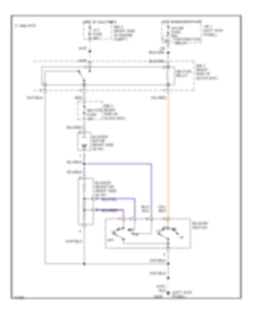
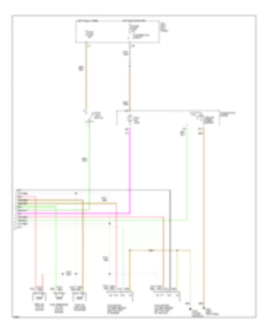
Heater Wiring Diagram for Toyota Pickup DX 1995
List of elements for Heater Wiring Diagram for Toyota Pickup DX 1995:
- (left kick panel)
- Alt fuse 80a
- Blower motor (right side of i/p)
- Blower resistor (right side of i/p)
- Blower switch
- C 1995 vftc
- G200
- Gauge fuse 10a
- Heater fuse 30a
- Heater relay
- Hot at all times
- Hot in run or start
- Integration relay
- J/b 1 (left kick panel)
- Off
- R/b 2 (right side of engine compt)
- R/b 3 (right side of glove box)
- Red
ANTI-LOCK BRAKES
Anti-lock Brake Wiring Diagrams for Toyota Pickup DX 1995
List of elements for Anti-lock Brake Wiring Diagrams for Toyota Pickup DX 1995:
- (ex usa column a/t) i9 (i/p harn, top left side of dash)
- (i/p harn, lower center of dash)
- (i/p harn, right end of dash)
- (i/p harn, right end of dash) i9
- (i/p harn, right kick panel) i14
- (i/p harn, top left side of dash)
- (i/p harn, top right end of dash) i11
- Abs actuator (front right of engine compartment)
- Abs deceleration sensor (below front console)
- Abs ecu (behind right side of i/p)
- Abs fuse 15a
- Abs relay (right side of engine compartment)
- Abs speed sensor (rear differential)
- Abs warning ind
- Anti-lock check connector (right rear corner of engine compartment)
- Bat
- Canada a/t & usa column a/t
- Combination meter
- Data link connector 1 (right side of engine compartment)
- Ecu-ig fuse 20a
- Fuse box (left kick panel)
- G117 (right rear of engine)
- G200 (left kick panel)
- Gauge fuse 10a
- Gnd
- Gs1
- Gs2
- Gst
- Hot at all times
- Hot in run
- I12 (a/t) i9 (m/t)
- I3 (canada m/t) i6 (usa m/t) i9 (a/t)
- I6 (usa column a/t) (i/p harn, lower center of dash)
- I9 (i/p harn, right side of dash)
- Ig1
- Integration relay
- J/b 1 (left kick panel)
- M/t & usa floor a/t
- Parking brake switch
- Pkb
- Rr+
- Rr-
- Rss
- Stop fuse 15a
- Stop light switch
- Stp
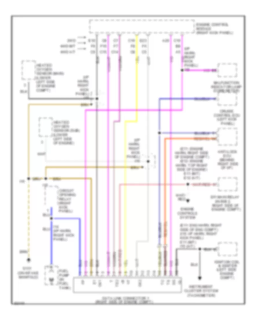
COMPUTER DATA LINES
2.4L
2.4L, Computer Data Lines for Toyota Pickup DX 1995
List of elements for 2.4L, Computer Data Lines for Toyota Pickup DX 1995:
- & igniter (left side
- (behind right side
- (e11- eng harn, right side of eng compt) (i15- i/p harn, right kick panel) e11 (m/t) i15 (a/t)
- (e11- engine harn, right side of engine compt) (e12- engine harn, top right side of engine) e11 (m/t) e12 (a/t)
- (i/p harn, right kick panel) i15
- (in r/b 2,
- (left kick
- (on intake manifold)
- (right side of engine compt)
- 2wd
- 4wd a/t
- 4wd m/t
- A20
- Anti-lock
- C10
- C14
- C15
- C16
- Circuit opening relay (right kick panel)
- Control ecu
- Cruise
- Data link connector 1
- E10
- E23
- Ecu
- Efi main relay
- Engine compt)
- Engine control module (right kick panel)
- Engine controls system
- F15
- Fuel pump (in fuel tank)
- G131
- Heated oxygen sensor (main) (lower left side of engine compt)
- Heated oxygen sensor (sub) (lower left side of engine)
- I14 (i/p harn, right kick panel)
- I15
- Ig-
- Ignition coil
- Instrument cluster system (tachometer)
- Kick panel) i15
- Malfunction indicator lamp (comb meter)
- Of i/p)
- Ox1
- Ox2
- Panel)
- Right side of engine compt)
- Te2
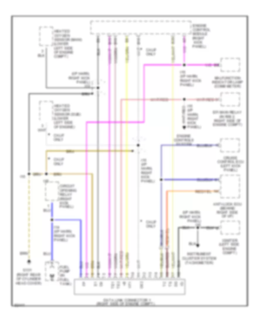
3.0L
3.0L, Computer Data Lines for Toyota Pickup DX 1995
List of elements for 3.0L, Computer Data Lines for Toyota Pickup DX 1995:
- (i/p harn, right kick panel) i15
- (left side
- (right rear of cylinder head cover)
- (right side of engine compt)
- Anti-lock ecu (behind right side of i/p)
- B10
- B15
- B16
- B20
- Calif only
- Circuit opening relay (right kick panel)
- Cruise control ecu (left kick panel)
- Data link connector 1
- Efi main relay (in r/b 2, right side of engine compt)
- Engine compt)
- Engine control module (right kick panel)
- Engine controls system
- Fuel pump (in fuel tank)
- G131
- Heated oxygen sensor (main) (lower left side of engine compt)
- Heated oxygen sensor (sub) (lower left side of engine)
- I14 (i/p harn, right kick panel)
- I15
- I15 (i/p harn, right kick panel)
- Ig-
- Igniter
- Instrument cluster system (tachometer)
- Malfunction indicator lamp (comb meter)
- Ox2
- Te1
- Te2
- Vf1
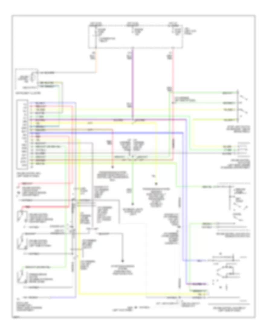
CRUISE CONTROL
Cruise Control Wiring Diagram for Toyota Pickup DX 1995
List of elements for Cruise Control Wiring Diagram for Toyota Pickup DX 1995:
- (a/t)
- (canada a/t)
- (canada a/t) (i/p harness, top left side of dash) i3
- (canada m/t) (i/p harness, top left side of dash)
- (i/p (i/p harness, top left side of dash)
- (i/p harness, left end of dash) (usa m/t)
- (i/p harness, left end of dash) (usa m/t, usa column a/t, canada a/t)
- (i/p harness, left end of dash) i1
- (i/p harness, lower center of dash)
- (i/p harness, lower center of dash) (except canada a/t)
- (i/p harness, top left side of dash)
- (usa a/t, canada m/t)
- (usa floor a/t)
- A/t
- Act
- C13
- Cancel
- Ccs
- Cruise control actuator (left rear corner of engine compartment)
- Cruise control clutch switch (left side of dash)
- Cruise control ecu (left side of dash)
- Cruise control ind
- Cruise control main relay (left side of dash)
- Cruise control main switch (combination switch)
- Cruise control vacuum pump (left side of engine compartment)
- Cruise control vacuum switch (left side of engine compartment)
- Data link connector 1 (right side of engine compartment)
- Ect
- Engine fuse 10a
- Exterior lights system (stop light)
- G200 (left kick panel)
- Gauge fuse 10a
- Harness, top left side of dash)
- Hot at all times
- Hot in on and start
- I1 (m/t, usa floor a/t)
- I22
- I3 (usa column a/t, canada a/t)
- I3 i1
- Igb
- Igc
- Instrument cluster
- Integration relay
- J/b 1 (left kick panel)
- M/t
- N&c
- O/d
- Parking brake switch (on base of parking brake lever)
- Pkb
- Red
- Resume/ accel
- Set/ coast
- Spd
- Starting/charging system (park/neutral position switch)
- Stop fuse 15a
- Stop light switch (on bracket, above brake pedal)
- Stp+
- Stp-
- Transmissions system (engine & electronically controlled transmission (w/ ect) (o/d relay) (w/o ect)
- Transmissions system (engine & electronically controlled transmission ecu)
- Vac
- Vss output
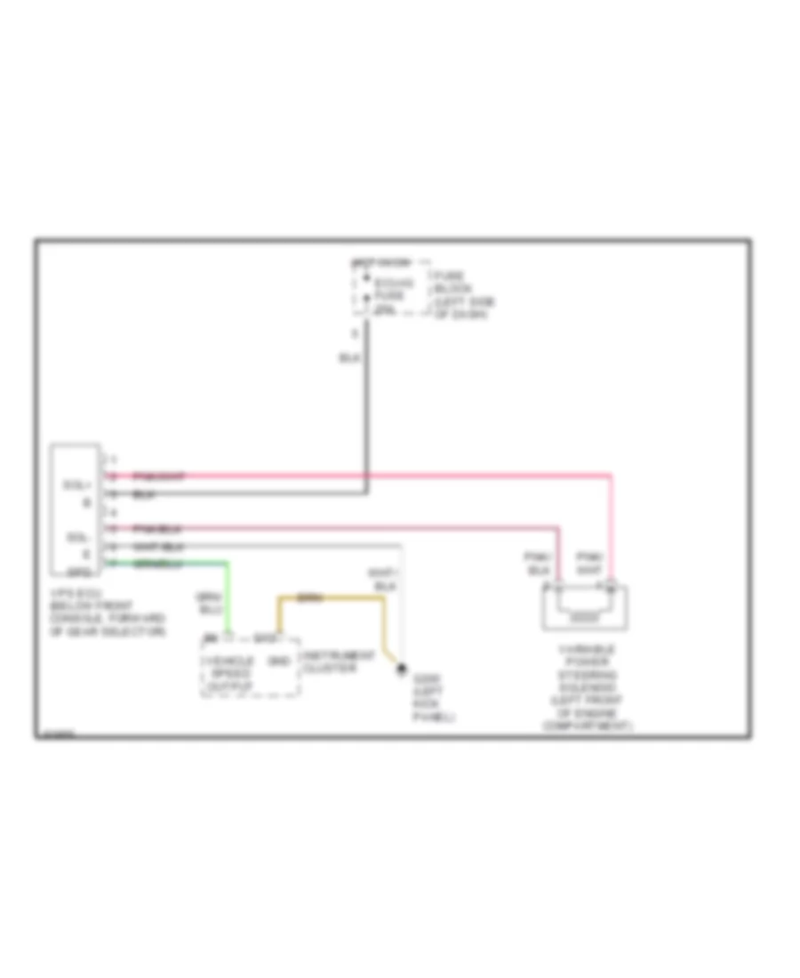
ELECTRONIC POWER STEERING
Electronic Power Steering Wiring Diagram for Toyota Pickup DX 1995
List of elements for Electronic Power Steering Wiring Diagram for Toyota Pickup DX 1995:
- (below front console, forward of gear selector)
- D12
- Ecu-ig fuse 20a
- Fuse block (left side of dash)
- G200 (left kick panel)
- Gnd
- Hot in on
- Instrument cluster
- Sol+
- Sol-
- Spd
- Variable power steering solenoid (left front of engine compartment)
- Vehicle speed output
- Vps ecu
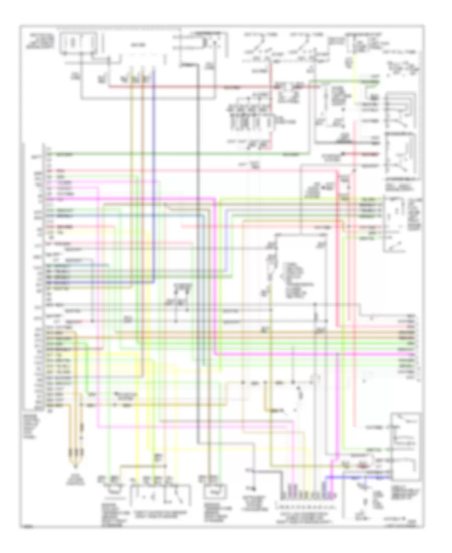
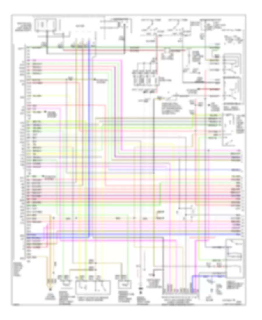
ENGINE PERFORMANCE
2.4L
2.4L, Engine Performance Wiring Diagrams, 2-Wheel Drive (1 of 2) for Toyota Pickup DX 1995
List of elements for 2.4L, Engine Performance Wiring Diagrams, 2-Wheel Drive (1 of 2) for Toyota Pickup DX 1995:
- #10
- #20
- (closed in park or neutral)
- (left
- (left kick panel)
- (right
- (right side of engine)
- (tachometer)
- A/t
- A3 j/b 1 kick panel)
- Acc
- Air condi- tioning system
- Alt fuse 80a
- Batt
- C10
- C11
- C12
- C13
- C14
- C15
- C16
- Circuit opening relay (behind right side of i/p)
- Cluster system
- Coil wire
- Data link connector #1 (check connector) (right side of engine compt.)
- Distributor
- E10
- E11
- E12
- E13
- E14
- E15
- E16
- E17
- E18
- E19
- E20
- E21
- E22
- E23
- E24
- E25
- E26
- Efi fuse 15a
- Efi main relay
- Egr
- Egr gas temperature sensor (right rear of engine)
- Engine control module (right kick panel)
- Engine coolant temperature sensor (right front of engine)
- Eo1
- Eo2
- Fpu
- Fuel injectors
- Fuel pump (in fuel tank)
- G100 (left fender)
- G120 (intake manifold)
- G200
- Hot at all times
- Hot in on or start
- Ht1
- Ht2
- Idl
- Ig2
- Igf
- Ign fuse 7.5a
- Igniter
- Ignition coil & igniter (left side of engine compt)
- Ignition switch
- Igt
- Instrument
- J/b 1 (left kick panel)
- Lock
- M/t
- Noise filter (left side engine compt)
- Nsw
- Ox1
- Ox2
- Park/ neutral position switch (on transmission)
- Pnk
- R/b 2 engine compt)
- Red
- Spd
- St1
- Sta
- Start
- Starter relay
- Starting
- Starting system
- Stj
- Stp
- System
- Te2
- Tha
- Thg
- Throttle position sensor
- Thw
- Vcc
- Volume air flow meter (left front engine compt)
- Vta
2.4L, Engine Performance Wiring Diagrams, 2-Wheel Drive (2 of 2) for Toyota Pickup DX 1995
List of elements for 2.4L, Engine Performance Wiring Diagrams, 2-Wheel Drive (2 of 2) for Toyota Pickup DX 1995:
- B12
- Combination meter
- Egr vsv (top of engine)
- Fuel pressure up vsv (top of engine)
- G120 (intake manifold)
- G200 (left kick panel)
- Gauge fuse 10a
- Hot at all times
- Hot in on or start
- Ht2
- Integration relay
- J/b 1 (left kick panel)
- Main heated oxygen sensor (bottom left of vehicle)
- Malf. ind. lamp
- Ox1
- Ox2
- Pair vsv (left side of engine)
- Pnk
- Red
- Stop fuse 15a
- Stop light switch
- Sub heated oxygen sensor (bottom left of engine)
- Vehicle speed sensor
2.4L, Engine Performance Wiring Diagrams, A/T with 4-Wheel Drive (1 of 2) for Toyota Pickup DX 1995
List of elements for 2.4L, Engine Performance Wiring Diagrams, A/T with 4-Wheel Drive (1 of 2) for Toyota Pickup DX 1995:
- #10
- #20
- (left
- (left kick panel)
- (right
- (right side of engine)
- (tachometer)
- 4wd
- A10
- A11
- A12
- A13
- A14
- A15
- A16
- A17
- A18
- A19
- A20
- A21
- A22
- A3 j/b 1 kick panel)
- Acc
- Air condi- tioning system
- Alt fuse 80a
- Batt
- C10
- C11
- C12
- C13
- C14
- C15
- C16
- Circuit opening relay (behind right side of i/p)
- Cluster system
- Coil wire
- Cruise control system
- Data link connector #1 (check connector) (right side of engine compt.)
- Distributor
- E10
- E11
- E12
- E13
- E14
- E15
- E16
- E17
- E18
- E19
- E20
- E21
- E22
- E23
- E24
- E25
- E26
- Efi fuse 15a
- Efi main relay
- Egr
- Egr gas temperature sensor (right rear of engine)
- Engine control module (right kick panel)
- Engine coolant temperature sensor (right front of engine)
- Eo1
- Eo2
- Fpu
- Fuel injectors
- Fuel pump (in fuel tank)
- G100 (left fender)
- G120 (intake manifold)
- G200
- Hot at all times
- Hot in on or start
- Ht1
- Ht2
- Idl
- Ig2
- Igf
- Ign fuse 7.5a
- Igniter
- Ignition coil & igniter (left side of engine compt)
- Ignition switch
- Igt
- Instrument
- J/b 1 (left kick panel)
- Knk
- Knock sensor (right side of engine)
- Lock
- Noise filter (left side engine compt)
- Od1
- Od2
- Ox1
- Ox2
- Park/neutral position switch (on transmission) (closed in park or neutral)
- Pnk
- Pwr
- R/b 2 engine compt)
- Red
- Sp2
- Spd
- St1
- Sta
- Start
- Starter relay
- Starting
- Starting system
- Stj
- Stp
- System
- Te2
- Tha
- Thg
- Throttle position sensor
- Thw
- Vcc
- Volume air flow meter (left front engine compt)
- Vta
2.4L, Engine Performance Wiring Diagrams, A/T with 4-Wheel Drive (2 of 2) for Toyota Pickup DX 1995
List of elements for 2.4L, Engine Performance Wiring Diagrams, A/T with 4-Wheel Drive (2 of 2) for Toyota Pickup DX 1995:
- (left kick panel)
- (on trans- mission)
- 4wd
- 4wd ind.
- A/t oil temp. ind.
- A/t only
- Add control relay (behind left side of i/p)
- Add indicator switch (right side of engine compt.)
- B10
- B12
- Cig fuse 15a
- Combination meter
- Cruise control system
- D12
- Diode (for back-up light) (right side of i/p)
- Diode (w/add) (right side of i/p)
- Egr vsv (on top of engine)
- Electronic controlled transmission pattern switch (a/t only)
- Electronic controlled transmission solenoid (on transmission)
- Floor shift
- Fuel pressure up vsv (on top of engine)
- G120 (intake manifold)
- G200
- Gauge fuse 10a
- Hot at all times
- Hot in acc or on
- Hot in on or start
- Ht2
- Instrument cluster system
- Integration relay
- J/b 1 (left kick panel)
- Main heated oxygen sensor (bottom left of vehicle)
- Malf. ind. lamp
- O/d main switch (a/t only)
- O/d off ind.
- Oil temp. switch (right side of engine)
- Ox1
- Ox2
- Pair vsv (left side of engine)
- Park/ neutral position switch n
- Pnk
- Power ind.
- Red
- Short pin (right side of engine compt.)
- Stop fuse 15a
- Stop light switch
- Sub heated oxygen sensor (bottom left of engine)
- Transfer case indicator switch (on transfer case)
- U.s. column shift
- Vehicle speed sensor
- W/ add
- W/ tach
- W/o add
- W/o tach
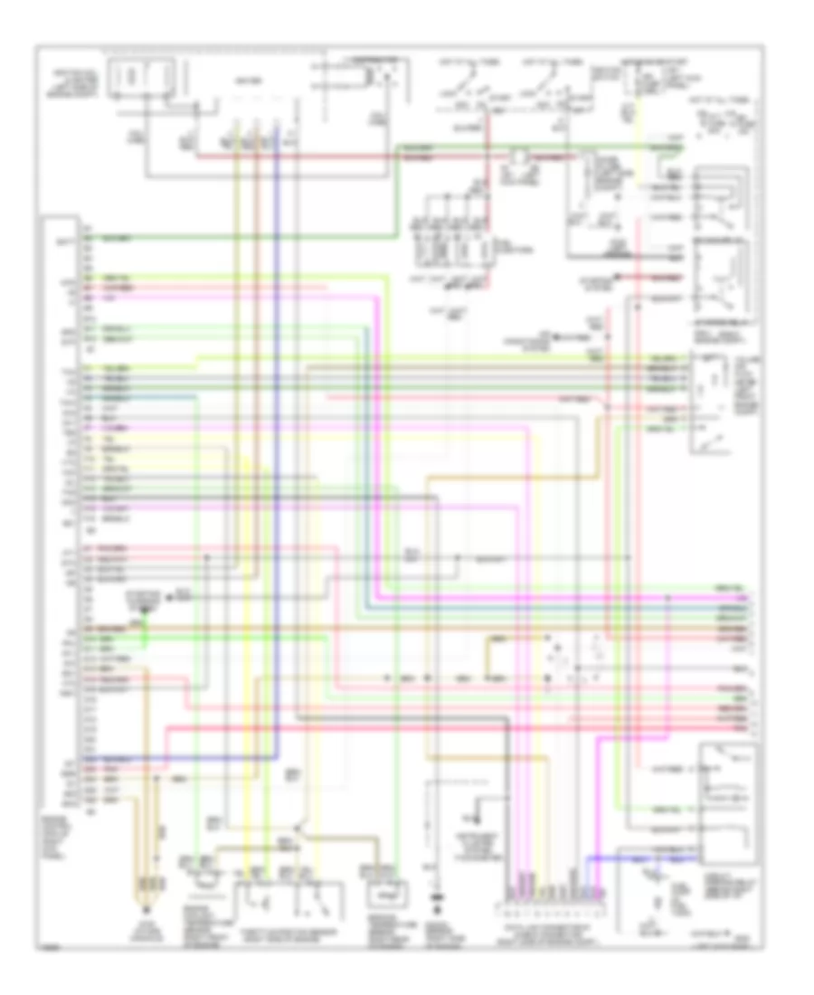
2.4L, Engine Performance Wiring Diagrams, M/T with 4-Wheel Drive (1 of 2) for Toyota Pickup DX 1995
List of elements for 2.4L, Engine Performance Wiring Diagrams, M/T with 4-Wheel Drive (1 of 2) for Toyota Pickup DX 1995:
- #10
- #20
- (left
- (left kick panel)
- (right
- (right side of engine)
- (tachometer)
- 4wd
- A3 j/b 1 kick panel)
- Acc
- Air conditioning system
- Alt fuse 80a
- B10
- B11
- B12
- Batt
- Circuit opening relay (behind right side of i/p)
- Cluster system
- Coil wire
- D10
- D11
- D12
- D13
- D14
- D15
- D16
- D17
- D18
- D19
- D20
- D21
- D22
- D23
- D24
- D25
- D26
- Data link connector #1 (check connector) (right side of engine compt.)
- Distributor
- E21
- Efi fuse 15a
- Efi main relay
- Egr
- Egr gas temperature sensor (right rear of engine)
- Engine control module (right kick panel)
- Engine coolant temperature sensor (right front of engine)
- Eo1
- Eo2
- F10
- F11
- F12
- F13
- F14
- F15
- F16
- Fpu
- Fuel injectors
- Fuel pump (in fuel tank)
- G100 (left fender)
- G120 (intake manifold)
- G200
- Hot at all times
- Hot in on or start
- Ht1
- Ht2
- Idl
- Ig2
- Igf
- Ign fuse 7.5a
- Igniter
- Ignition coil & igniter (left side of engine compt)
- Ignition switch
- Igt
- Instrument
- J/b 1 (left kick panel)
- Knk
- Knock sensor (right side of engine)
- Lock
- Noise filter (left side engine compt)
- Nsw
- Ox1
- Ox2
- Pnk
- R/b 2 engine compt)
- Red
- Spd
- St1
- Sta
- Start
- Starter relay
- Starting
- Starting/ charging system
- Stj
- Stp
- System
- Te2
- Tha
- Thg
- Throttle position sensor
- Thw
- Vcc
- Volume air flow meter (left front engine compt)
- Vta
2.4L, Engine Performance Wiring Diagrams, M/T with 4-Wheel Drive (2 of 2) for Toyota Pickup DX 1995
List of elements for 2.4L, Engine Performance Wiring Diagrams, M/T with 4-Wheel Drive (2 of 2) for Toyota Pickup DX 1995:
- (intake manifold)
- (left kick panel)
- 4wd ind.
- B12
- Combination meter
- D12
- Egr vsv (top of engine)
- Fuel pressure up vsv (top of engine)
- G120
- G200
- Gauge fuse 10a
- Hot at all times
- Hot in on or start
- Ht2
- Integration relay
- J/b 1 (left kick panel)
- Main heated oxygen sensor (bottom left of vehicle)
- Malf. ind. lamp
- Ox1
- Ox2
- Pair vsv (left side of engine)
- Pnk
- Red
- Stop fuse 15a
- Stop light switch
- Sub heated oxygen sensor (bottom left of engine)
- Transfer case indicator switch (on transfer case)
- Vehicle speed sensor
3.0L
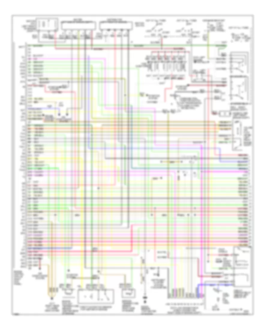
3.0L, Engine Performance Wiring Diagrams (1 of 2) for Toyota Pickup DX 1995
List of elements for 3.0L, Engine Performance Wiring Diagrams (1 of 2) for Toyota Pickup DX 1995:
- #10
- #20
- (left
- (left front of engine)
- (left kick panel)
- (left side of engine compt)
- (right
- (tachometer)
- 4wd
- A/c
- A/t
- A/t 4wd
- A10
- A11
- A12
- A13
- A14
- A15
- A16
- A17
- A18
- A19
- A20
- A21
- A22
- Acc
- Act
- Acv
- Air
- Air condit- ioning system
- Alt fuse 80a
- Am1
- Am2
- B10
- B11
- B12
- B13
- B14
- B15
- B16
- Batt
- C10
- C11
- C12
- C13
- C14
- C15
- C16
- C17
- C18
- C19
- C20
- C21
- C22
- C23
- C24
- C25
- C26
- Calif. models
- Circuit opening relay (behind left side of i/p)
- Cluster system
- Coil wire
- Conditioning
- Cruise control system
- Data link connector #1 (check connector) (right side of engine compt.)
- Distributor
- E21
- Efi fuse 15a
- Efi main relay
- Egr
- Egr gas temperature sensor (right side of engine)
- Engine control module (right kick panel)
- Engine coolant temperature sensor (center rear of engine)
- Eo1
- Eo2
- Fpu
- Fuel
- Fuel pump (in fuel tank)
- G100 fender)
- G117 (right rear cylinder head cover)
- G200
- Hot at all times
- Hot in on or start
- Ht2
- Idl
- Ig-
- Ig2
- Igf
- Ign fuse 7.5a
- Igniter
- Ignition coil (left front of engine compt.)
- Ignition switch
- Igt
- Injectors
- Instrument
- J/b 1 (left kick panel)
- J/b 1 kick panel)
- Knk
- Knock sensor (top center of engine)
- Lock
- M/t
- Noise filter (left front engine compt)
- Od1
- Od2
- Oil
- Ox2
- Park/neutral position switch (on transmission) (closed in park or neutral)
- Pnk
- Pwr
- R/b 2 engine compt)
- Red
- Sel2
- Sp2
- Spd
- St1
- Sta
- Start
- Starter relay
- Starting
- Starting system
- Stj
- Stp
- System
- Tha
- Thg
- Tho1
- Tho2
- Throttle position sensor (top center of engine)
- Thw
- Volume air flow meter (left front engine compt)
- Vta
3.0L, Engine Performance Wiring Diagrams (2 of 2) for Toyota Pickup DX 1995
List of elements for 3.0L, Engine Performance Wiring Diagrams (2 of 2) for Toyota Pickup DX 1995:
- (a/t only)
- (a/t)
- (left kick panel)
- (m/t)
- (right side of i/p)
- 4wd ind.
- 4wd w/ a/t
- 4wd w/ m/t
- A/t
- A/t 4wd
- A/t oil temp. ind.
- A/t only
- A/t w/ 4wd only
- Add control relay (behind left side of i/p)
- Add indicator switch (left front of engine compt.)
- B10
- B12
- Cig fuse 15a
- Combination meter
- Cruise control system
- D12
- Diode
- Diode (for back-up light) (right side of i/p)
- Egr vsv (right side of engine compt.)
- Electronic controlled transmission pattern switch (a/t only)
- Electronic controlled transmission solenoid (on transmission)
- Floor shift
- Fuel pressure up vsv (right side of engine compt.)
- G117 (right rear cylinder head cover)
- G200
- Gauge fuse 10a
- Hot at all times
- Hot in acc or on
- Hot in on or start
- Ht1
- Ht2
- Instrument cluster system
- Integration relay
- J/b 1 (left kick panel)
- M/t: w/add
- Main heated oxygen sensor (bottom left of vehicle)
- Malf. ind. lamp
- O/d main switch (a/t only)
- O/d off ind.
- Oil temperature sensor (on transmission)
- Ox1
- Ox2
- Pair vsv (right side of engine compt.)
- Park/ neutral position switch (on trans- mission)
- Pnk
- Power ind.
- Red
- Short pin (a/t) (left front of engine compt.)
- Stop fuse 15a
- Stop light switch
- Sub heated oxygen sensor (bottom left of vehicle) (california)
- Transfer case indicator switch (on transfer case)
- Transfer fluid temperature sensor (on transfer case)
- Transfer pressure switch (a/t: w/add) (right rear of engine)
- U.s. column shift
- Vehicle speed sensor
- W/ add
- W/ tach
- W/add
- W/o add
- W/o tach
EXTERIOR LIGHTS
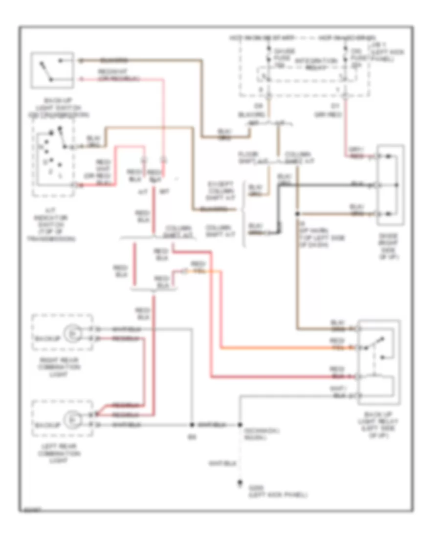
Back-up Lamps Wiring Diagram for Toyota Pickup DX 1995
List of elements for Back-up Lamps Wiring Diagram for Toyota Pickup DX 1995:
- A/t
- A/t indicator switch (top of transmission)
- Back up light relay (left side of i/p)
- Back-up light switch (on transmission)
- Backup
- Cig fuse 15a
- Column shift a/t
- Diode (right side of i/p)
- Except column shift a/t
- Floor shift a/t
- G200 (left kick panel)
- Gauge fuse 10a
- Hot in acc or on
- Hot in on or start
- I3(canada) i6(usa)
- I9 (i/p harn, top left side of dash)
- Integration relay
- J/b 1 (left kick panel)
- Left rear combination light
- M/t
- Right rear combination light
Exterior Lamps Wiring Diagram for Toyota Pickup DX 1995
List of elements for Exterior Lamps Wiring Diagram for Toyota Pickup DX 1995:
- (i/p harn, lower center of dash) i6
- (i/p harn,top left side of dash) i3(excpt usa column shift a/t) i9(usa column shift a/t)
- Alt fuse 80a
- B8 (body harn, near right rear wheelwell)
- C10
- C11
- C12
- Combination meter
- Combination switch
- D11
- G100 (left front fender)
- G200 (left kick panel)
- G203 (right kick panel)
- Haz-horn fuse 15a
- Hazard switch
- Head
- High mount stop light
- Hot at all times
- Hot in on or start
- I13 (i/p harn, left end of dash)
- I3(excpt usa column shift a/t) i9(usa column shift a/t)
- I6 (i/p harn, lower center of dash)
- I9 (i/p harn, top left side of dash)
- Integration relay
- J/b 1 (left kick panel)
- Left front parking light
- Left front turn signal light
- Left license plate light
- Left rear combination light
- Left turn
- Light switch
- Off
- Park
- R/b 2 (right side of engine compartment)
- Right front parking light
- Right front turn signal light
- Right license plate light
- Right rear combination light
- Right turn
- Stop
- Stop fuse 15a
- Stop light switch (on bracket above brake pedal)
- Tail
- Tail fuse 15a
- Taillight relay
- Turn
- Turn fuse 10a
- Turn signal flasher (left side of i/p)
- Turn signal switch
GROUND DISTRIBUTION
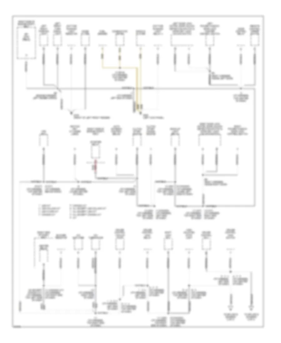
Ground Distribution Wiring Diagram (1 of 3) for Toyota Pickup DX 1995
List of elements for Ground Distribution Wiring Diagram (1 of 3) for Toyota Pickup DX 1995:
- (right end of dash) r/b 3
- (right side of engine compt) r/b 2
- A a/t
- A/c amplifier
- A/c thermistor
- All except canada a/t
- All except usa column a/t
- All except usa m/t
- Auto antenna control relay
- B3 (body harness, inside left door)
- B5 (body harness, inside right door)
- Back-up light relay
- Blower resistor
- Canada a/t
- Canada m/t
- Clutch start cancel switch
- Clutch start switch
- Combination meter
- Cruise control ecu
- Cruise control main relay
- Cruise control main switch
- Cruise control vacuum pump
- D12
- Daytime running light relay 4
- Daytime running light resistor
- Door control relay
- E8 (engine harness, left fender apron)
- Efi main relay
- Fuel sender
- G100 (front of left front fender)
- G200 (left kick panel)
- Heater relay
- High mounted stop light
- I1 (canada) (i/p harness, left end of dash)
- I1 (i/p harness, left end of dash)
- I10 (i/p harness, right side of dash)
- I11 (canada a/t) (i/p harness, top right end of dash)
- I11 (i/p harness, top right end of dash)
- I11 (m/t) (i/p harness, top right end of dash)
- I11 (usa) (i/p harness, top right end of dash)
- I13 (a/t) (i/p harness, right end of dash)
- I20 (except canada a/t) (i/p harness, top left side of dash)
- I3 (i/p harness, top center of dash)
- I3 (i/p harness, top left side of dash)
- I3 (or i9) (i/p harness, top center of dash)
- I3 (usa) (i/p harness, top left side of dash)
- I6 (canada) (i/p harness, lower left side of dash)
- I6 (i/p harness, lower center of dash)
- I8 (a/t) (i/p harness, behind radio)
- I9 (canada) (i/p harness, top center of dash)
- I9 (i/p harness, top center of dash)
- I9 (m/t) (i/p harness, top center of dash)
- Ignition key cylinder light
- Left door lock motor, door unlock detection switch & door key lock/ unlock switch
- Left front parking light
- Left front turn signal light
- Left power window/ door lock master control switch
- Noise filter
- Radio & player
- Remote control mirror switch
- Right door lock motor, door unlock detection switch & door key lock/ unlock switch
- Right power window/ door lock control switch
- Shift lock ecu
- Starter relay
- To splice i6 (diagram 2 of 3)
- Usa column a/t
- Usa floor a/t
- Usa m/t
- Vps ecu
Ground Distribution Wiring Diagram (2 of 3) for Toyota Pickup DX 1995
List of elements for Ground Distribution Wiring Diagram (2 of 3) for Toyota Pickup DX 1995:
- (i/p harness, left end of dash) i1
- (i/p harness, left end of dash) i9
- (i/p harness, lower center of dash) i6
- (i/p harness, right end of dash) i12 (m/t &
- (i/p harness, top left side of dash) i3 (or i9)
- (i/p harness, top left side of dash) i9 (a/t all) i3
- (i/p harness, top left side of dash) i9 (a/t)
- (i/p harness, top right end of dash)
- (i/p harness, top right end of dash) i11
- (i/p harness, top right end of dash) i11 (m/t)
- (i4 only)
- A/c switch
- All except canada a/t
- All except usa column a/t
- All except usa floor a/t
- All except usa m/t
- Anti- lock relay
- Anti-lock deceleration sensor
- Anti-lock ecu
- B10
- Canada a/t
- Canada m/t
- Cigarette lighter
- Circuit opening relay
- Clock
- Combination meter
- Cruise control clutch switch
- Cruise control vacuum switch
- D10
- E12 (engine harness, top right side of engine)
- From cruise control main switch (diagram 1 of 3)
- From high mounted stop light (diagram 1 of 3)
- Glove box light switch
- Heater blower switch
- I11 (i/p harness, top right end of dash)
- I11 (m/t &
- I12 (i/p harness, right end of dash)
- I13 (a/t only) (i/p harness, right end of dash)
- I3 (canada) (i/p harness, top left side of dash)
- I3 (i/p harness, top left side of dash)
- I3 (usa a/t) (i/p harness, top left side of dash)
- I6 (i/p harness, lower center of dash)
- I6 (usa) (i/p harness, lower center of dash)
- I8 (i/p harness, behind radio)
- I9 (i/p harness, left end of dash)
- I9 (i/p harness, top left side of dash)
- Key interlock solenoid
- Main daytime running light relay
- O/d main switch
- Parking brake switch
- Rheostat
- Right front parking light
- Right front turn signal
- To splice i9 (diagram 3 of 3)
- Transfer l4 position switch indicator
- Transfer neutral position switch
- Transfer switch position indicator
- Turn signal flasher
- Usa column a/t
- Usa floor a/t
- Usa m/t
- Vacuum solenoid valve (for 2wd)
- Vacuum solenoid valve (for 4wd)
- Wiper & washer switch
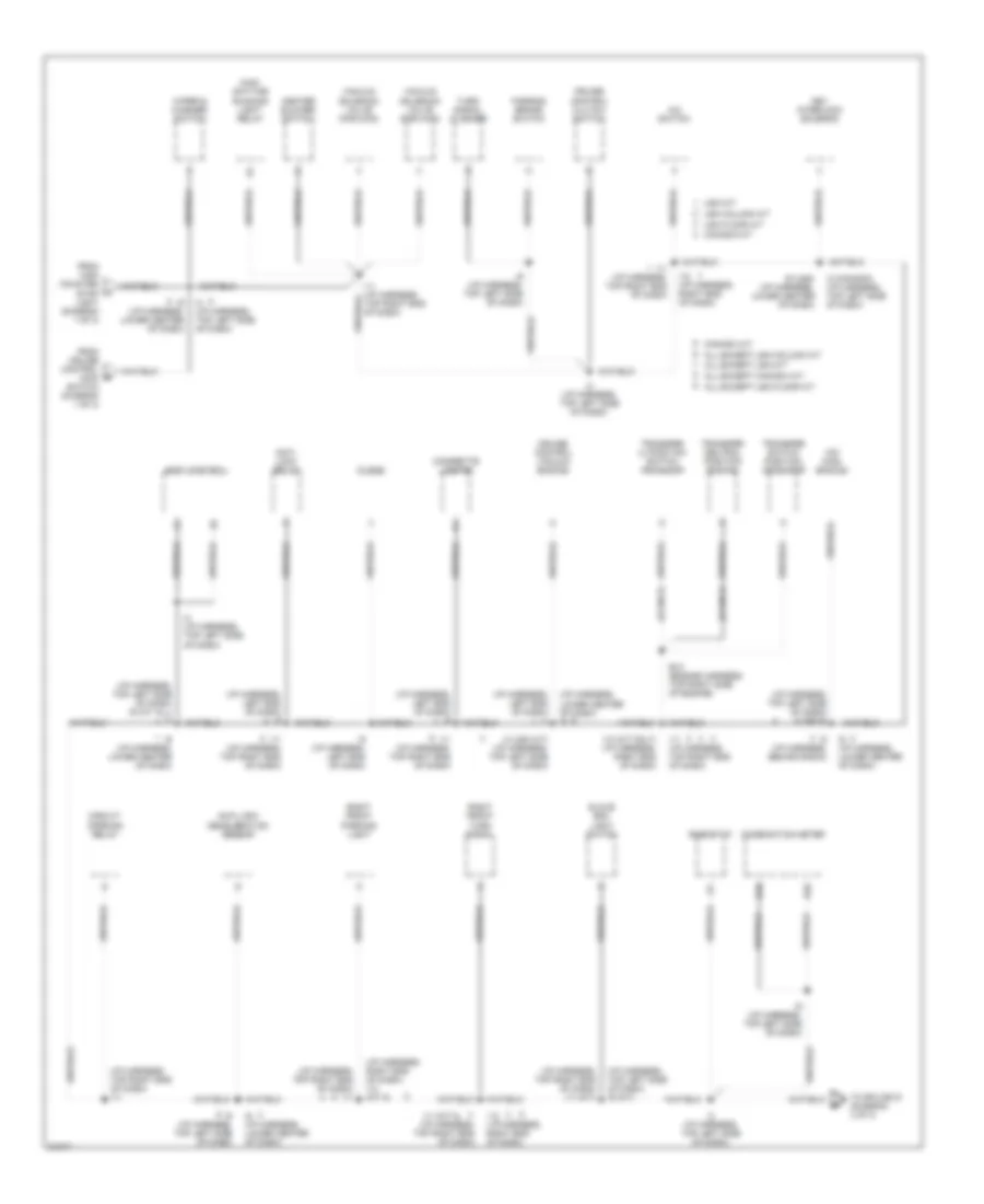
Ground Distribution Wiring Diagram (3 of 3) for Toyota Pickup DX 1995
List of elements for Ground Distribution Wiring Diagram (3 of 3) for Toyota Pickup DX 1995:
- (i/p harness, top left side of dash) i3
- 22r-e 2.2l i4 only
- 2wd
- 3vz-e 3.0l v6 only
- 4wd a/t
- 4wd m/t
- A17
- B12
- B6 (body harness, under front center of cargo box floor)
- B8 (body harness, under cargo box floor, next to right rear wheelwell)
- Brake fluid level switch
- Buckle switch
- C11
- C13
- C26
- Canada m/t
- D13
- D24
- D26
- Data link connector 1
- Dimmer switch
- E10 (a/t) (engine harness, right side of engine)
- E10 (engine harness, right side of engine)
- E10 (m/t) (engine harness, right side of engine)
- E11 (a/t) (engine harness, right side of engine compt)
- E11 (m/t) (engine harness, right side of engine compt)
- E12 (engine harness, top right side of engine)
- E12 (m/t) (engine harness, top right side of engine)
- E13
- E14
- E19 (a/t) (engine harness, right side of engine compt)
- E24
- E26
- Engine control module
- From combi- nation c meter (diagram 2 of 3)
- Fuel pump
- G131 (rear of engine)
- G201 (right end of dash)
- I11 (i/p harness, top right end of dash)
- I15 (a/t) (i/p harness, right kick panel)
- I15 (i/p harness, right kick panel)
- I15 (m/t) (i/p harness, right kick panel)
- I3 (i/p harness, top left side of dash)
- I6 (i/p harness, lower center of dash)
- I9 (i/p harness, top left side of dash)
- Integration relay
- J/b 1 (left kick panel)
- Left license plate light
- Left rear combination light
- Light control switch
- Main heated oxygen sensor
- Nca
- Only) (4wd m/t
- Right license plate light
- Right rear combination light
- Sub heated oxygen sensor
- Usa column a/t
- Usa floor a/t
- Usa m/t
- Vehicle speed sensor
- Volume air flow meter
HEADLIGHTS
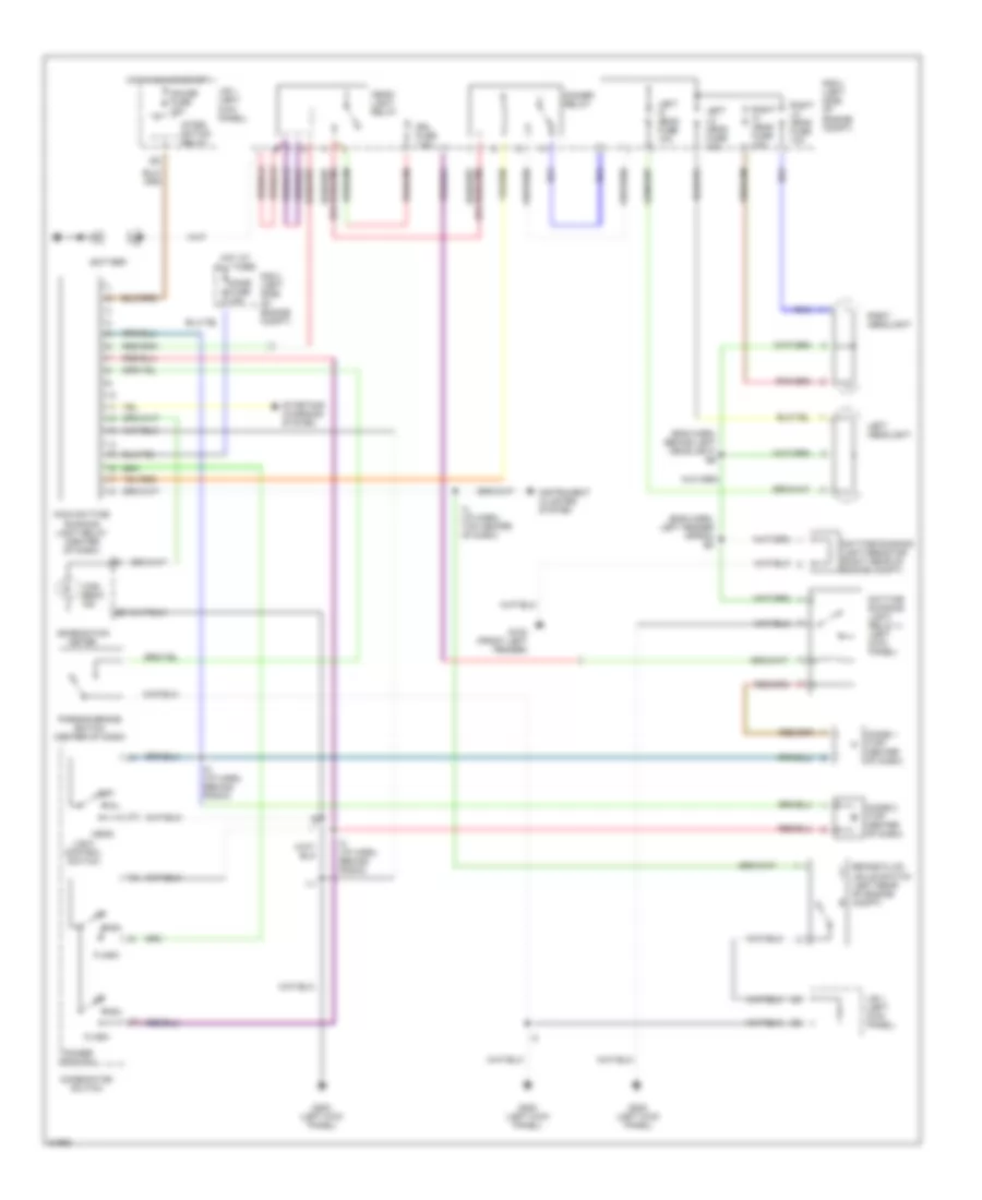
Headlight Wiring Diagram, with DRL for Toyota Pickup DX 1995
List of elements for Headlight Wiring Diagram, with DRL for Toyota Pickup DX 1995:
- (eng harn, behind left headlight) e6
- (eng harn, left fender apron) e8
- Battery
- Brake fluid levle switch (left rear of engine compt)
- Combination meter
- Combination switch
- Daytime running light relay 4 (left kick panel)
- Daytime running light resistor (right rear of engine compt)
- Dimmer relay
- Dimmer switch
- Diode 1 (top center of dash)
- Diode 2 (top center of dash)
- Dome fuse 15a
- Drl fuse 7.5a
- Flash
- G100 (front left fender)
- G200 (left kick panel)
- Gauge fuse 10a
- Head
- Head- light relay
- High
- High beam ind
- Hot at all times
- Hot in on or start
- I11
- I4 (i/p harn, top center of dash)
- I8 (i/p harn, behind radio)
- Instrument cluster system
- Integ- ration relay
- J/b 1 (left kick panel)
- Left headlight
- Left hi head fuse 10a
- Left lo head fuse 10a
- Light control switch
- Main daytime running light relay (center of dash)
- Off
- Parking brake switch (center of dash)
- R/b 2 (left side of engine compt)
- Right headlight
- Right hi head fuse 10a
- Right lo head fuse 10a
- Starting/ charging system
- Tail
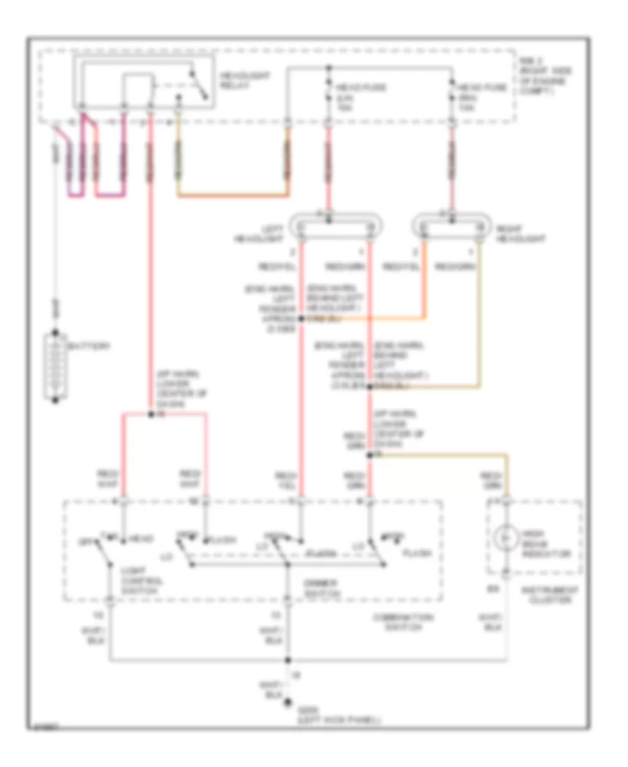
Headlight Wiring Diagram, without DRL for Toyota Pickup DX 1995
List of elements for Headlight Wiring Diagram, without DRL for Toyota Pickup DX 1995:
- (eng harn, (eng harn, left fender apron) (3.0l)e8
- (eng harn, behind left headlight) e6(2.2l)
- (eng harn, left fender apron) (3.0)e8
- (i/p harn, lower center of dash) i6
- Battery
- Behind left headlight) e6(2.2l)
- Combination switch
- Dash) i6
- Dimmer switch
- Flash
- G200 (left kick panel)
- Head
- Head fuse (lh) 10a
- Head fuse (rh) 10a
- Headlight relay
- High
- High beam indicator
- Instrument cluster
- Left headlight
- Light control switch
- Off
- R/b 2 (right side of engine compt)
- Right headlight
- Tail
HORN
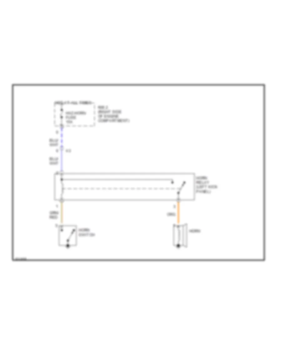
Horn Wiring Diagram for Toyota Pickup DX 1995
List of elements for Horn Wiring Diagram for Toyota Pickup DX 1995:
- Haz-horn fuse 15a
- Horn
- Horn relay (left kick panel)
- Horn switch
- Hot at all times
- R/b 2 (right side of engine compartment)
INSTRUMENT CLUSTER
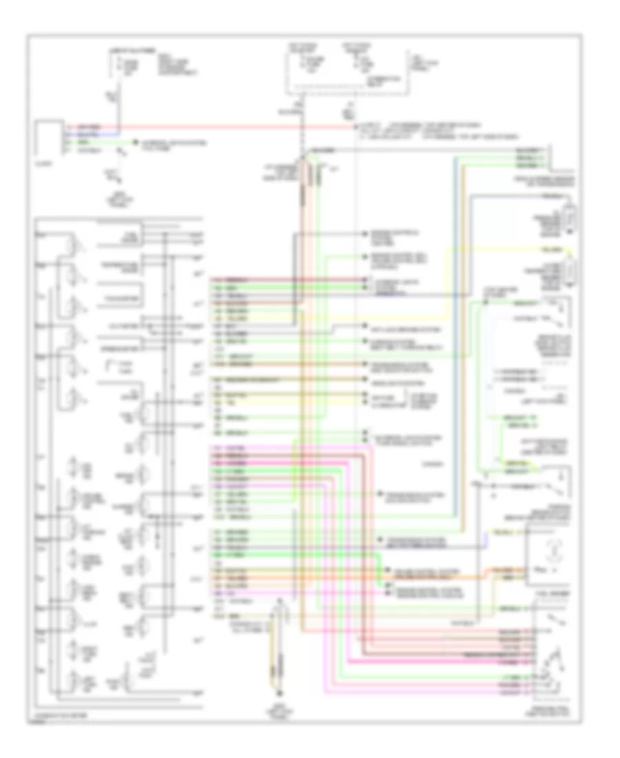
Instrument Cluster Wiring Diagram for Toyota Pickup DX 1995
List of elements for Instrument Cluster Wiring Diagram for Toyota Pickup DX 1995:
- (canada a/t) (all other)
- (i/p harness, top center of dash)
- (i/p harness, top left side of dash)
- (top center of dash) i4
- (usa column a/t)
- 4wd ind
- A/t
- A/t fluid temp ind
- A/t parking ind
- A10
- A11
- A12
- Abs ind
- Alternator
- Anti-lock brakes system
- Brake fluid level switch (brake fluid reservoir)
- Brake ind
- C10
- C12
- Canada
- Charge ind
- Check engine ind
- Cig fuse 15a
- Clock
- Combination meter
- Cruise control ind
- Cruise control system (cruise control ecu)
- D10
- D11
- D12
- Daytime running light relay (center of dash)
- Dome fuse i5a
- Engine control ecu, cruise control ecu, & pps ecu
- Engine control system (engine control module)
- Engine controls system (igniter)
- Exterior lights system (turn signal switch)
- Fuel gauge
- Fuel ind
- Fuel sender
- G200 (left kick panel)
- Gauge fuse 10a
- Headlights system
- High beam ind
- Hot at all times
- Hot in run and acc
- Hot in run or start
- I3 i9
- I4 (or i7) (all m/t, usa floor a/t, canada a/t) i3
- I9 (i/p harness, top left side of dash)
- Ign fuse
- Illum
- Integration relay
- Interior lights system (rheostat)
- Interior lights system (tail fuse)
- J/b 1 (left kick panel)
- Left turn ind
- O/d off ind
- Oil gauge
- Oil ind
- Oil pressure sender (top of engine)
- Park/neutral position switch
- Parking brake switch (behind center of dash)
- Pwr ind
- R/b 2 (right side of engine compartment)
- Right turn ind
- Seat belt ind
- Speedometer
- Starting/ charging system
- Tachometer
- Temperature gauge
- Transmission system (add indicator switch)
- Transmission system (ect pattern switch)
- Transmission system (o/d main switch)
- Usa
- Vehicle speed sensor (on transmission)
- Voltmeter
- W/ tach
- W/o tach
- Warning system (seat belt warning relay)
- Water temperature sender (top of engine)
INTERIOR LIGHTS
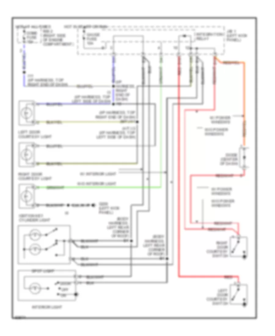
Courtesy Lamps Wiring Diagram for Toyota Pickup DX 1995
List of elements for Courtesy Lamps Wiring Diagram for Toyota Pickup DX 1995:
- (a/t) i3 (i/p harness, top left side of dash)
- (body harness, left rear corner of roof) b1
- (i/p harness, right end of dash) i12
- (i/p harness, top right end of dash) (m/t) i11
- D10
- D12
- Diode (center of dash)
- Dome fuse 15a
- Door
- G200 (left kick panel)
- Gauge fuse 10a
- Hot at all times
- Hot in start or run
- I11 (i/p harness, top right end of dash)
- I3 (i/p harness, top left side of dash)
- Igntion key cylinder light
- Integration relay
- Interior light
- J/b 1 (left kick panel)
- Left door courtesy light
- Left door courtesy switch
- Off
- R/b 2 (right side of engine compartment)
- Red
- Right door courtesy light
- Right door courtesy switch
- Spot light
- W/ interior light
- W/ power windows
- W/o interior light
- W/o power windows
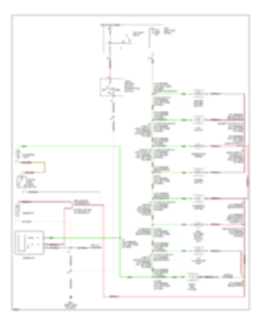
Instrument Illumination Wiring Diagram for Toyota Pickup DX 1995
List of elements for Instrument Illumination Wiring Diagram for Toyota Pickup DX 1995:
- (except column a/t) i9 (i/p harness, top left side of dash)
- (i/p harness, behind radio) (column a/t) i8
- (i/p harness, behind radio) (usa floor a/t, canada a/t) i8
- (i/p harness, behind radio) i8 (a/t)
- (i/p harness, behind radio) i8 (floor a/t)
- (i/p harness, top center of dash)
- (i/p harness, top center of dash) i4 (canada)
- (i/p harness, top left side of dash)
- (i/p harness, top left side of dash) (usa column a/t, m/t) i3
- (i/p harness, top right side of dash) (except column a/t) i21
- (m/t) i11 (a/t) i9
- (usa column a/t) i7 (i/p harness, top center of dash)
- 13 (usa column a/t) i21 (usa m/t, usa floor a/t) (i/p harness, top right side of dash)
- A/c switch
- A/t illumination light
- A10
- Behind radio)
- Cigarette lighter
- Combination meter
- Deluxe and standard m/t
- Ect pattern select switch (a/t)
- Ex deluxe and standard m/t
- G201 (right side of dash)
- Glove box light
- Glove box light switch
- Hazard switch
- Head
- Heater blower switch
- Hot at all times
- I3 (usa) (i/p harness, top left side of dash)
- I4 17 (usa column a/t) (i/p harness, (canada column a/t) (i/p harness, of dash)
- I7 (usa column a/t) (usa m/t, i9 usa floor a/t) (i/p harness, top left side of dash)
- I8 (i/p harness, behind radio)
- I9 (i/p harness, top left side of dash)
- I9 (m/t) (i/p harness, top left side of dash)
- I9 (usa floor a/t, canada a/t) (i/p harness, top left side of dash)
- I9 (usa) (canada) i8 (i/p harness, behind radio)
- J/b 1 (left kick panel)
- Light control switch (combination switch)
- Off
- Radio and player
- Rheostat
- Tail
- Tail fuse 15a
- Taillight relay
- Top center
POWER ANTENNA
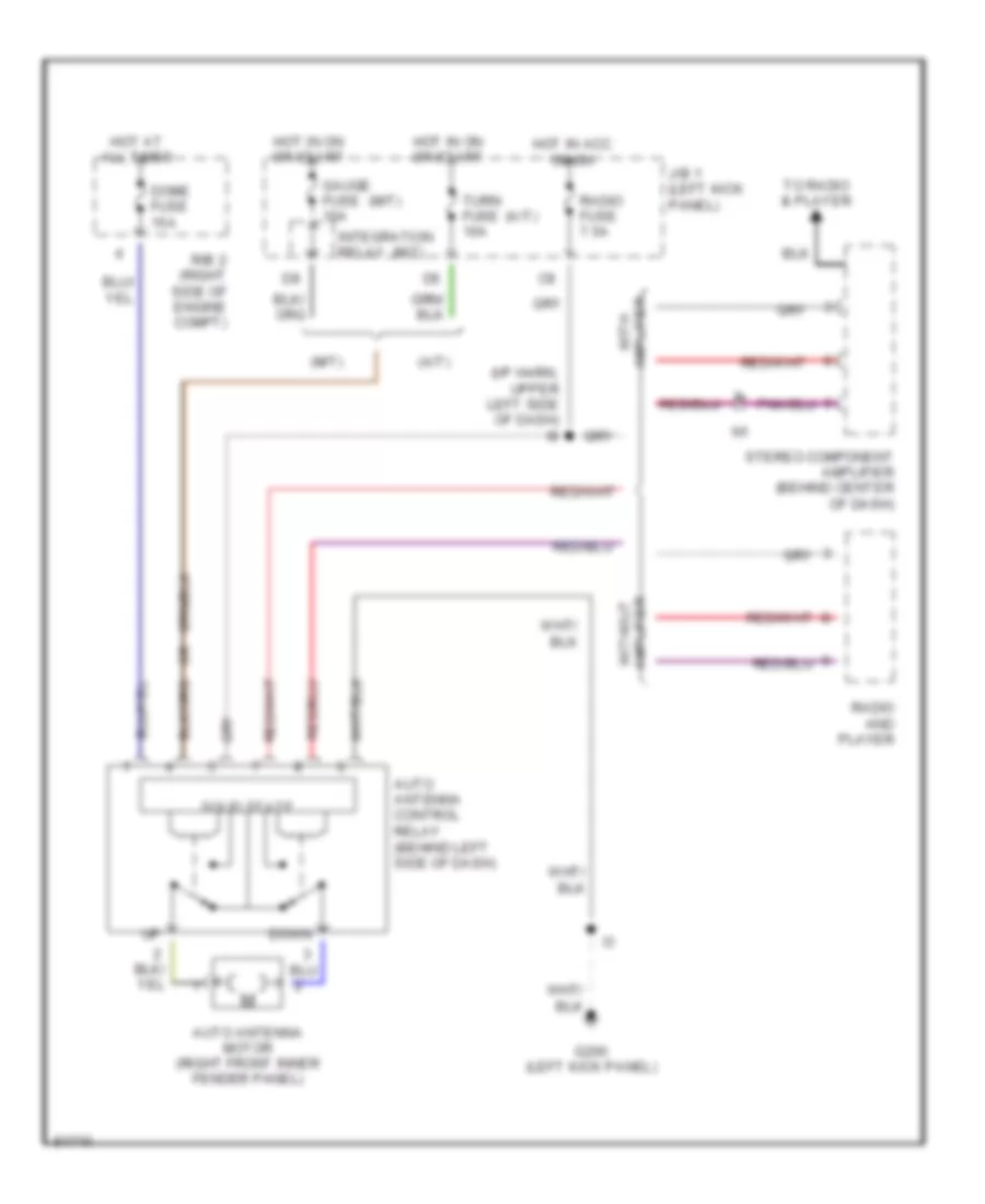
Power Antenna Wiring Diagram for Toyota Pickup DX 1995
List of elements for Power Antenna Wiring Diagram for Toyota Pickup DX 1995:
- (a/t)
- (i/p harn, upper left side of dash) i9
- (m/t)
- Auto antenna control relay (behind left side of dash)
- Auto antenna motor (right front inner fender panel)
- Dome fuse 15a
- Down
- G200 (left kick panel)
- Gauge fuse 10a
- Hot at all times
- Hot in acc or on
- Hot in on or start
- Integration relay
- J/b 1 (left kick panel)
- R/b 2 (right side of engine compt)
- Radio and player
- Radio fuse 7.5a
- Solid state
- Stereo component amplifier (behind center of dash)
- To radio & player
- Turn fuse 10a
- With amplifier
- Without amplifier
POWER DISTRIBUTION
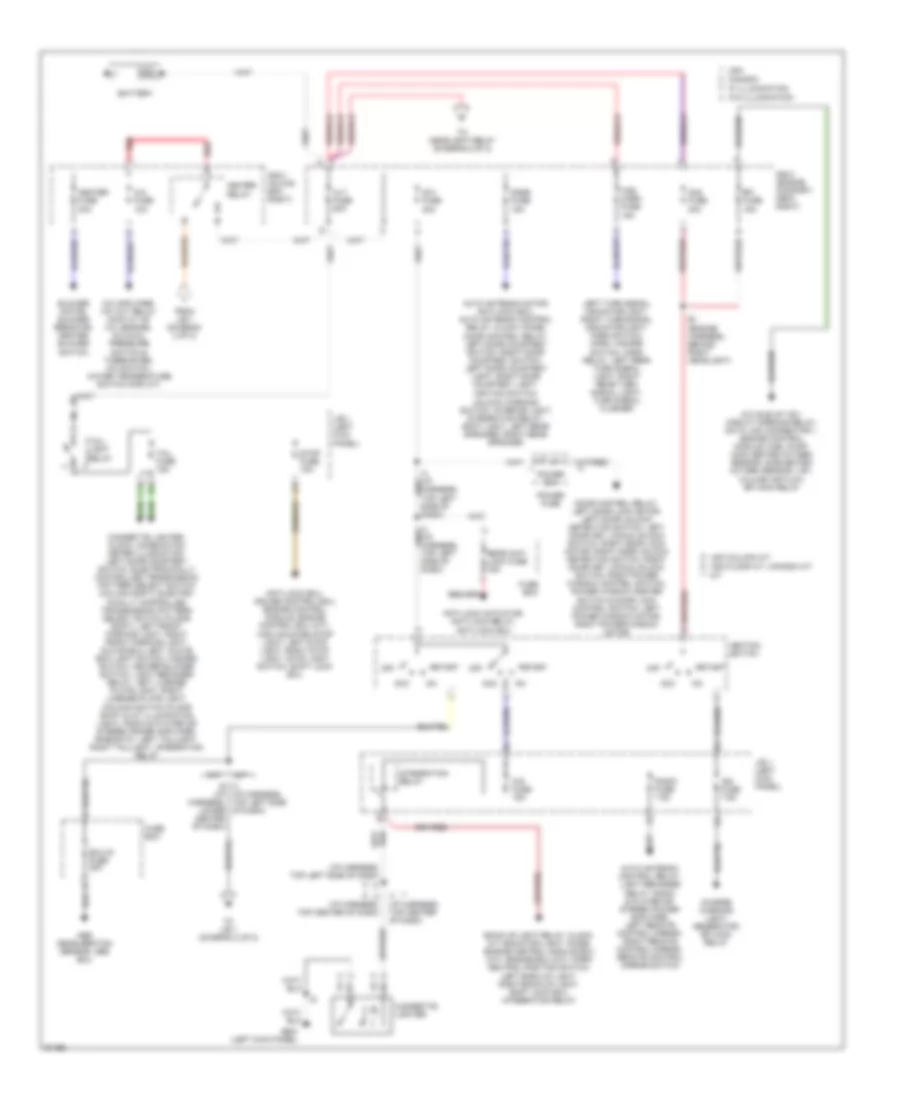
Power Distribution Wiring Diagram (1 of 2) for Toyota Pickup DX 1995
List of elements for Power Distribution Wiring Diagram (1 of 2) for Toyota Pickup DX 1995:
- (i/p harness, top left side of dash)
- 40a
- A/c amplifier, a/c cut relay (4wd a/t of 3.0l engine), a/c dual pressure switch & thermister, a/c switch, water temperature switch (for a/t)
- A/c fuse 10a
- A/c idle-up vsv, circuit opening relay, data link connector 1, engine control module, fuel pump, main heated oxygen sensor, sub-heated oxygen sensor, vsv, volume air flow, efi main relay
- A/t
- Abs deceleration sensor, abs ecu
- Acc
- Alt fuse 80a
- Am1 fuse
- Am2 fuse 30a
- Anti-lock actuator, anti-lock relay, anti-lock ecu
- Anti-lock ecu, cruise control ecu, engine control module, engine control ecu (a/t), high mounted stop light, left stop light, right stop light, stop light switch, shift lock ecu
- Auto antenna control relay, light reminder relay, radio & player or stereo power amplifier, left remote control mirror, right remote control mirror, remote control mirror switch
- Auto antenna motor, anti-lock ecu, auto antenna control relay, clock, diode, door control relay, left door courtesy switch, right door courtesy switch, left door courtesy light, right door courtesy light, ignition switch,
- Back-up light relay, clock, a/t indicator light, diode, engine control module ecu (a/t), engine ecu (m/t), park neutral position switch, left back-up light, right back-up light, shift lock ecu, integration relay
- Battery
- Blower motor, blower resistor, heater blower switch
- C14
- Canada
- Charge warning light, generator, efi main relay
- Cig fuse 15a
- Cigarette lighter
- Cigarette lighter, clock, combination meter illumination, left door courtesy switch, electronically controlled transmission pattern select switch (column shift), electro- nically controlled transmission pattern select switch (floor shift), left front parking light, right front parking light, glove box light, glove box light switch, hazard switch, heater blower switch, light reminder relay, left license plate light, right license plate light, o/d main switch (floor shift & a/t illumination light), radio & player or stereo power amplifier, rheostat, left taillight, right taillight, integration relay
- Dome fuse 15a
- Door control relay, left door lock motor, left door unlock detection switch, left door key lock & unlock switch, right door lock motor, right door unlock detection switch, right door key lock & unlock switch, right power window control switch, power window master switch & door lock control switch, left power window motor, right power window motor
- E1 (engine harness, behind right headlight)
- Ecu-ig fuse 20a
- Efi fuse 15a
- From j/b 1 (diagram 2 of 2)
- Fuse box
- G200 (left kick panel)
- Haz- horn fuse 15a
- Heater fuse 30a
- Heater relay
- I3 (i/p harness, top left side of dash)
- I3 i6 (i/p harness, lower center of dash)
- I4 (i/p harness, top center of dash)
- I7 (i/p harness, top center of dash)
- Ign fuse 7.5a
- Ignition switch
- Integration relay
- J/b 1 (left kick panel)
- Left turn signal indicator light, right turn signal indicator light, horn switch, horn, hazard switch, horn relay, left rear turn signal light, right rear turn signal light, turn signal flasher
- M/t
- Off
- Power 30a
- Power fuse
- R/b 2 (engine compart- ment right)
- R/b 3 (glove box right)
- Radio fuse 7.5a
- Rear anti lock fuse 15a
- Red
- Start
- Stop fuse 15a
- Tail fuse 15a
- Tail- light relay
- To headlight relay (diagram 2 of 2)
- To j/b 1 (diagram 2 of 2)
- Unlock warning switch, interior light, integration relay, spot light, left rear speaker, right rear speaker
- Usa
- Usa column a/t
- Usa floor a/t, canada a/t
- W/ illumination
- W/o illumination
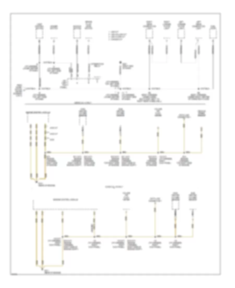
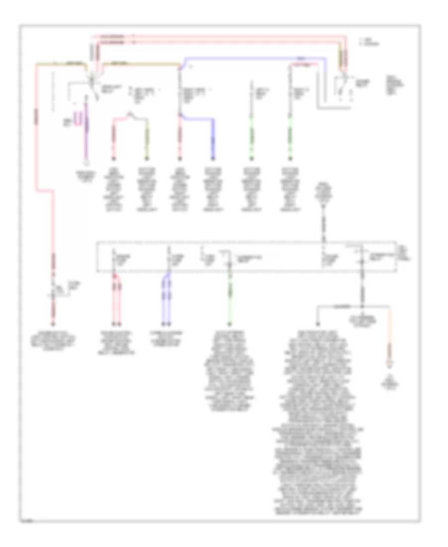
Power Distribution Wiring Diagram (2 of 2) for Toyota Pickup DX 1995
List of elements for Power Distribution Wiring Diagram (2 of 2) for Toyota Pickup DX 1995:
- (2.2l engine)
- (3.0l engine)
- Add indicator light, anti-lock actuator, anti-lock check connector, add control relay, anti-lock ecu, auto antenna control relay, back-up light switch (m/t), brake fluid level switch, back-up light relay, a/t parking indicator light, combination meter, cruise control indicator light, malfunction indicator lamp, o/d off indicator light, a/t indicator light, rear anti-lock warning light, seat belt warning light, 4wd indicator light, cruise control ecu, main daytime running light relay (canada), diode (add), door control relay, diode (back-up light), electronically controlled transmission pattern select switch (column shift), electronically controlled transmission pattern select switch (floor shift), engine control module (engine & electronically controlled transmission ecu (a/t), engine ecu (m/t)), fuel sender, heater blower switch, indicator switch (transfer position, a/t), & transfer position switch (add) (2.2l engine w/ electronically controlled transmission), indicator switch (transfer position, a/t), transfer fluid temperature sensor & transfer pressure switch, indicator switch (transfer position, m/t), light reminder relay, oil pressure sender, oil temperature switch (2.2l engine 4wd a/t), o/d main switch (column shift), o/d main switch (floor shift & a/t illumination light), park/neutral position switch (neutral start switch) & back-up light switch, parking brake switch, left back-up light, right back-up light, shift lock ecu, transfer neutral position switch, vsv (2wd, add), vsv (4wd, add), vehicle speed sensor, water temperature sensor, integration relay, heater relay
- Auto antenna control relay, left turn signal indicator light, right turn signal indicator light, turn signal switch, engine control module ecu (a/t), engine ecu (m/t),
- C15
- C16
- Canada
- Cruise control main switch, cruise control ecu, cruise control main relay, generator
- Daytime running light resistor, daytime running light relay no 4, left headlight
- Daytime running light resistor, daytime running light relay no 4, right headlight
- Dimmer relay
- Dimmer switch, light control switch, daytime running light relay no 4, diode no 1, diode no 2
- Drl 7.5a
- Engine fuse 10a
- From r/b 2 (diagram 1 of 2)
- From splices i3 or i6 (diagram 1 of 2)
- Fuse box
- Gauge fuse 10a
- Headlight relay
- High beam indicator light, dimmer switch, left headlight, light control switch
- High beam indicator light, dimmer switch, right headlight, light control switch
- I9 (i/p harness, top left side of dash)
- Integration relay
- J/b 1 (left kick panel)
- Left front turn signal light, right front turn signal light, hazard switch, o/d solenoid (2.2l), o/d main switch (column shift), o/d relay, left rear turn signal light, right rear turn signal light, turn signal flasher, integration relay
- Left head left lo head 10a
- Left hi head 10a
- R/b 2 (engine compart- ment left)
- Red
- Right head right lo head 10a
- Right hi head 10a
- To r/b 3 (diagram 1 of 2)
- Turn fuse 10a
- Usa
- Wiper & washer switch, washer motor, wiper motor
- Wiper fuse 20a
POWER DOOR LOCKS
Power Door Lock Wiring Diagram for Toyota Pickup DX 1995
List of elements for Power Door Lock Wiring Diagram for Toyota Pickup DX 1995:
- B3 (body harn, inside left door)
- B5 (body harn, inside right door)
- Dome fuse 15a
- Door lock control relay (left side of i/p)
- G200 (left kick panel)
- Hot at all times
- I9 (m/t) i3 (a/t) (i/p harn, top left side of dash)
- Left door courtesy switch
- Left door key lock/unlock switch
- Left door lock control switch
- Left door lock motor & unlock detection switch
- Lock
- Lock timer
- Power fuse (left kick panel)
- Power fuse 30a
- R/b 2 (right side of engine compartment)
- Red
- Right door courtesy switch
- Right door key lock/unlock switch
- Right door lock control switch
- Right door lock motor & unlock detection switch
- Solid state
- Unlock
- Unlock timer
- Unlock warning switch (ignition switch)
POWER MIRRORS
Power Mirror Wiring Diagram for Toyota Pickup DX 1995
List of elements for Power Mirror Wiring Diagram for Toyota Pickup DX 1995:
- B3 (body harness, inside left door)
- Down
- Down right
- G200 (left kick panel)
- Hot in acc or on
- J/b 1 (left kick panel)
- Left
- Left remote control mirror
- Operation switch
- Pnk
- Radio fuse 7.5a
- Remote control mirror switch
- Right
- Right remote control mirror
- Select switch
- Up left
POWER WINDOWS
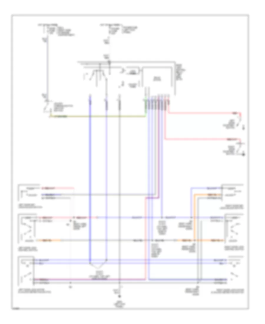
Power Window Wiring Diagram for Toyota Pickup DX 1995
List of elements for Power Window Wiring Diagram for Toyota Pickup DX 1995:
- (a/t)
- (m/t)
- D10
- D12
- Diode (left side of i/p, right of combination meter)
- Door control relay (behind left side of i/p)
- Down
- Driver's
- G200 (left kick panel)
- Gauge fuse 10a
- Hot at all times
- Hot in on or start
- I3 (i/p harn, top left side of i/p)
- I3 (i/p harn, top left side of i/p) i11 (i/p harn, top right side of i/p)
- In-line fuse (left kick panel)
- Integration relay
- J/b 1 (left kick panel)
- Left door courtesy switch (at base of left "a" pillar)
- Left power window motor
- Lock
- Normal
- Passenger's
- Power fuse 30a
- Power window master switch
- Red
- Right door courtesy switch (at base of right "b" pillar)
- Right power window control switch
- Right power window motor (in right door)
- Solid state
RADIO
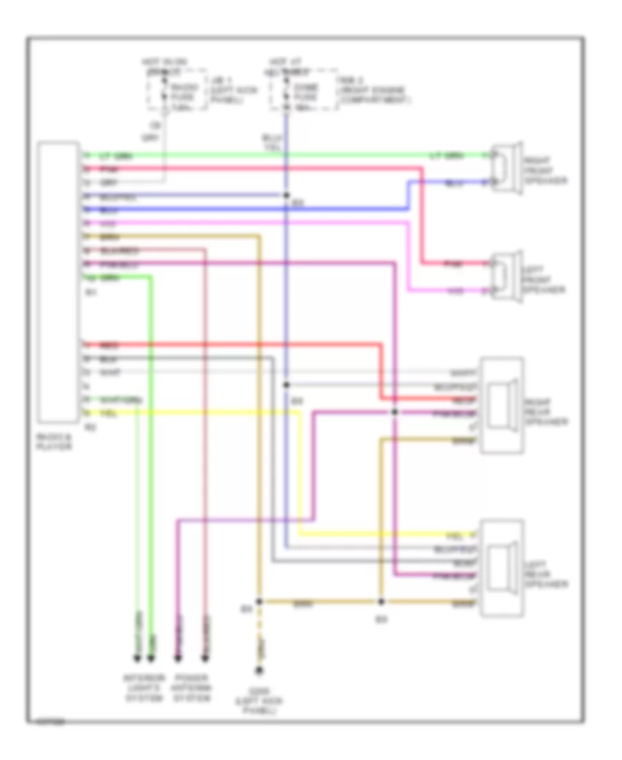
Radio Wiring Diagrams, with Amplifier for Toyota Pickup DX 1995
List of elements for Radio Wiring Diagrams, with Amplifier for Toyota Pickup DX 1995:
- Dome fuse 15a
- G200 (left kick panel)
- Hot at all times
- Hot in on or acc
- Interior lights system
- J/b 1 (left kick panel)
- Left front speaker
- Left rear speaker
- Pnk
- Power antenna system
- R/b 2 (right engine compartment)
- Radio & player
- Radio fuse 7.5a
- Red
- Red
- Right front speaker
- Right rear speaker
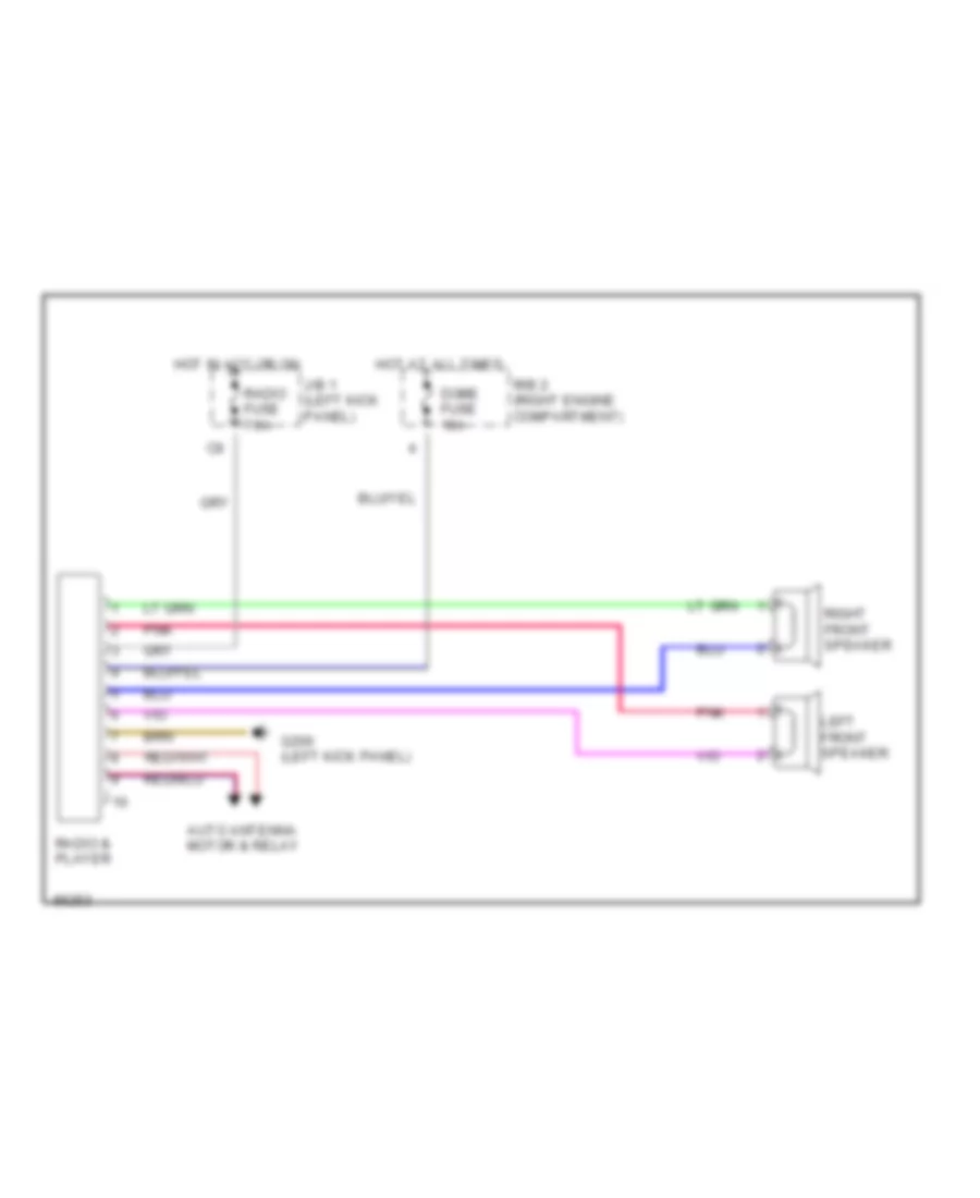
Radio Wiring Diagrams, without Amplifier for Toyota Pickup DX 1995
List of elements for Radio Wiring Diagrams, without Amplifier for Toyota Pickup DX 1995:
- Auto antenna motor & relay
- Dome fuse 15a
- G200 (left kick panel)
- Hot at all times
- Hot in acc or on
- J/b 1 (left kick panel)
- Left front speaker
- Pnk
- R/b 2 (right engine compartment)
- Radio & player
- Radio fuse 7.5a
- Right front speaker
SHIFT INTERLOCKS
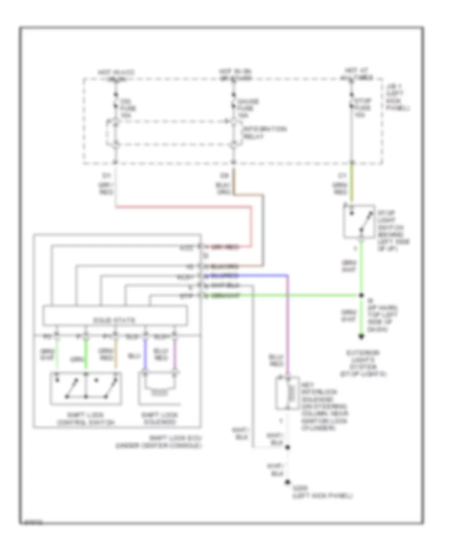
Shift Interlock Wiring Diagram for Toyota Pickup DX 1995
List of elements for Shift Interlock Wiring Diagram for Toyota Pickup DX 1995:
- Acc
- Cig fuse 15a
- Exterior lights system (stop lights)
- G200 (left kick panel)
- Gauge fuse 10a
- Hot at all times
- Hot in acc or on
- Hot in on or start
- I9 (i/p harn, top left side of dash)
- Integration relay
- J/b 1 (left kick panel)
- Key interlock solenoid (on steering column, near ignition lock cylinder)
- Kls+
- Shift lock control switch
- Shift lock ecu (under center console)
- Shift lock solenoid
- Sls+
- Sls-
- Solid state
- Stop fuse 15a
- Stop light switch (behind left side of i/p)
- Stp
STARTING/CHARGING
Charging Wiring Diagram for Toyota Pickup DX 1995
List of elements for Charging Wiring Diagram for Toyota Pickup DX 1995:
- Alt fuse 80a
- Am1 fuse 40a
- Battery
- Battery ground
- Charge warning light
- Comb- ination meter
- Daytime runn- ing light relay main (canada) (behind center of dash)
- Engine fuse 10a
- Generator
- Hot in on or start
- I9 (i/p harness, behind center of dash)
- Ign fuse 7.5a
- J/b 1 (on left kick panel)
- Nca
- R/b 2 (on right side of engine compt)
- Red
Starting Wiring Diagram for Toyota Pickup DX 1995
List of elements for Starting Wiring Diagram for Toyota Pickup DX 1995:
- (2.4 column a/t) (engine harness, top right side of engine)
- (2wd 2.4l)
- (3.0l)
- (4wd 2.4l)
- (on top right rear of engine) cold start injector
- (right kick panel, i/p harness) (3.0l) i15
- (right kick panel, i/p harness) (3.ol) i15
- (right kick panel, i/p harness) i14
- (right kick panel, i/p harness) i15
- (right side of engine, engine harness) (3.0l) e20
- A/t
- A/t only
- Acc
- Alt fuse 80a
- Am1 fuse 40a
- Battery
- Battery ground
- Circuit opening relay
- Clutch start cancel switch (m/t)
- Clutch start switch (m/t) (above clutch pedal)
- E11 (2.4) (engine harness, right side of engine compt)
- E12 e11 (2.4 floor a/t) (engine harness, right side of engine compt)
- Engine control module (on right kick panel)
- G200 (left kick panel)
- I1 (i/p harness, (left end of dash)
- I15 (i/p harness, right kick panel)
- I3 (i/p harness, top left side of dash)
- Ignition switch
- M/t
- M/t only
- Nca
- Off
- P/ n
- Park/ neutral position switch (on trans- mission)
- R/b 2 (right side of engine compt)
- Sta
- Start
- Start injector time switch (2.4l: on right side of engine; 3.0l: on top rear of engine)
- Starter
- Starter relay
- Stj
TRANSMISSION
2.4L
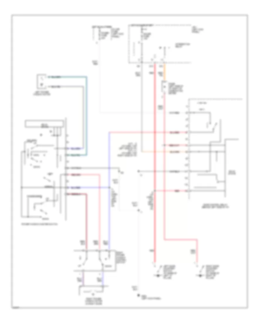
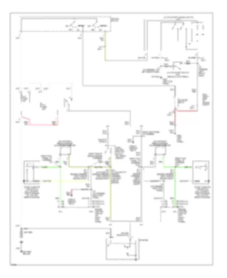
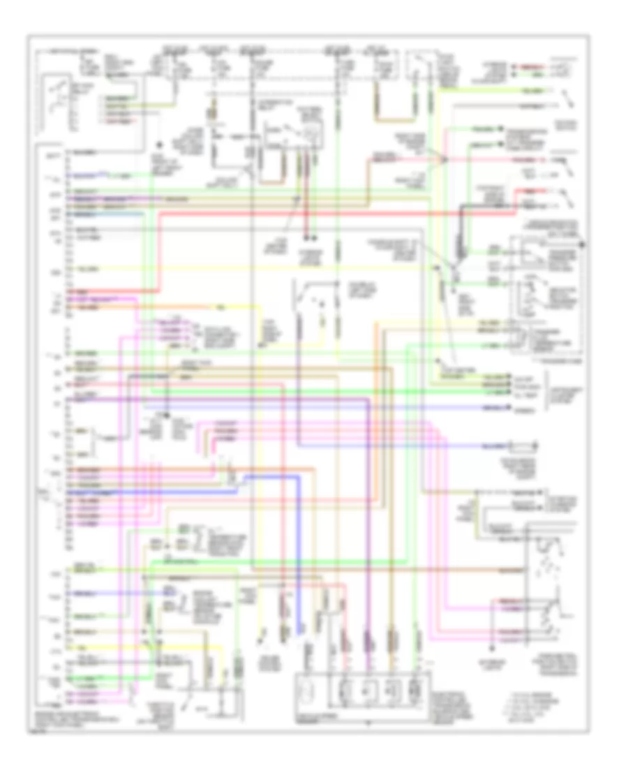
2.4L, Overdrive Wiring Diagram, 2WD for Toyota Pickup DX 1995
List of elements for 2.4L, Overdrive Wiring Diagram, 2WD for Toyota Pickup DX 1995:
- (i/p harn, top center of dash)
- Cruise control ecu (lower left side of i/p)
- Ect
- Engine control module (right kick panel)
- G200 (left kick panel)
- Gauge fuse 10a
- Hot in on or start
- I4 (i/p harn, top center of dash)
- Instrument cluster
- Integration relay
- J/b 1 (left kick panel)
- O/d
- O/d main switch (column shft- center of dash) (floor shft- below center console)
- O/d off indic.
- O/d relay (behind left side of dash)
- O/d solenoid (on transmission)
- Turn fuse 10a
2.4L, Transfer Case Wiring Diagram, A/T for Toyota Pickup DX 1995
List of elements for 2.4L, Transfer Case Wiring Diagram, A/T for Toyota Pickup DX 1995:
- (eng harn, right side eng compt)
- (i/p harn, right end of dash)
- (i/p harn, right kick panel)
- (i/p harn, top right of dash)
- (i9: i/p harn, top right of dash i3: i/p harn, top left of dash)
- (not used)
- (right kick panel) diode d6
- (right side eng compt) (2wd add) vsv
- (right side eng compt) (4wd add) vsv
- (transfer case)
- 1995 vftc c
- 4wd
- 4wd indic.
- A/t parking indic.
- A10
- A12
- Add
- Add control relay (behind left side of dash)
- Add indicator switch (on add actuator, on front of front differential)
- E11
- E12
- Engine and electronic controlled transmission ecu (right kick panel)
- G200 (left kick panel)
- Gauge fuse 10a
- Hot in on or start
- I11
- I13
- I15
- I9 (can) i3 (usa)
- Indicator switch (for transfer position)
- Instrument cluster
- Integration relay
- J/b 1 (left kick panel)
- Park/neutral position switch (right side of transmission)
- Red
- Short pin (left front of engine compt)
- Transfer neutral position switch (on transfer case)
- W/ add
- W/o
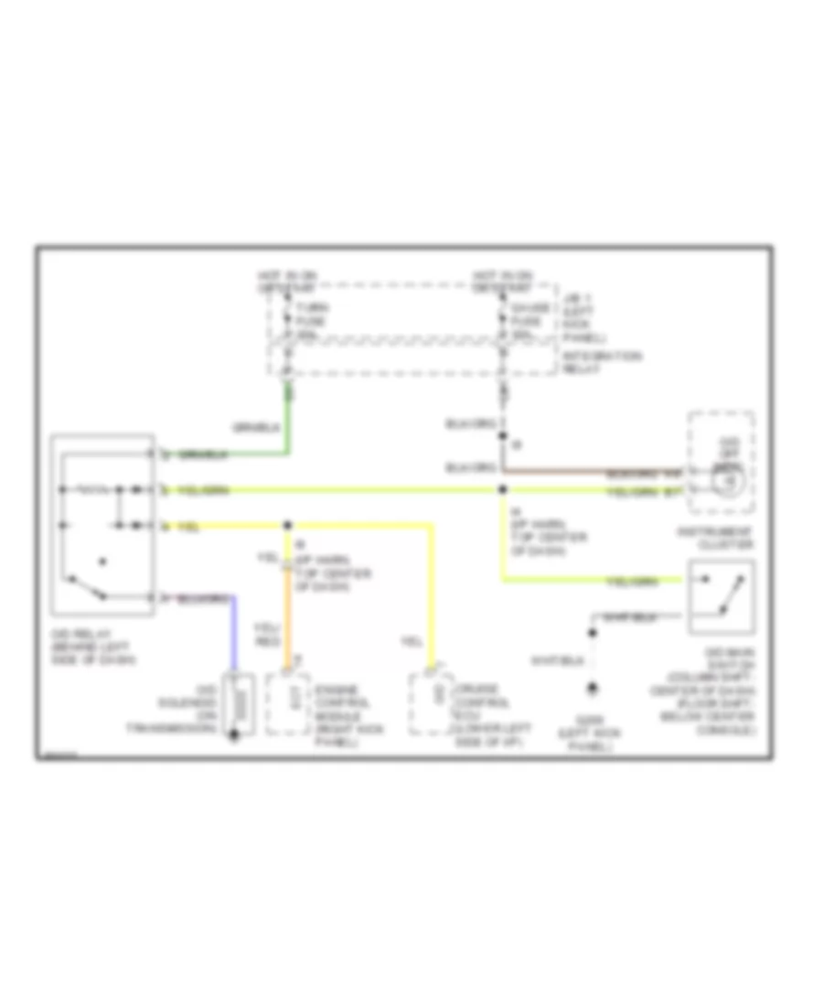
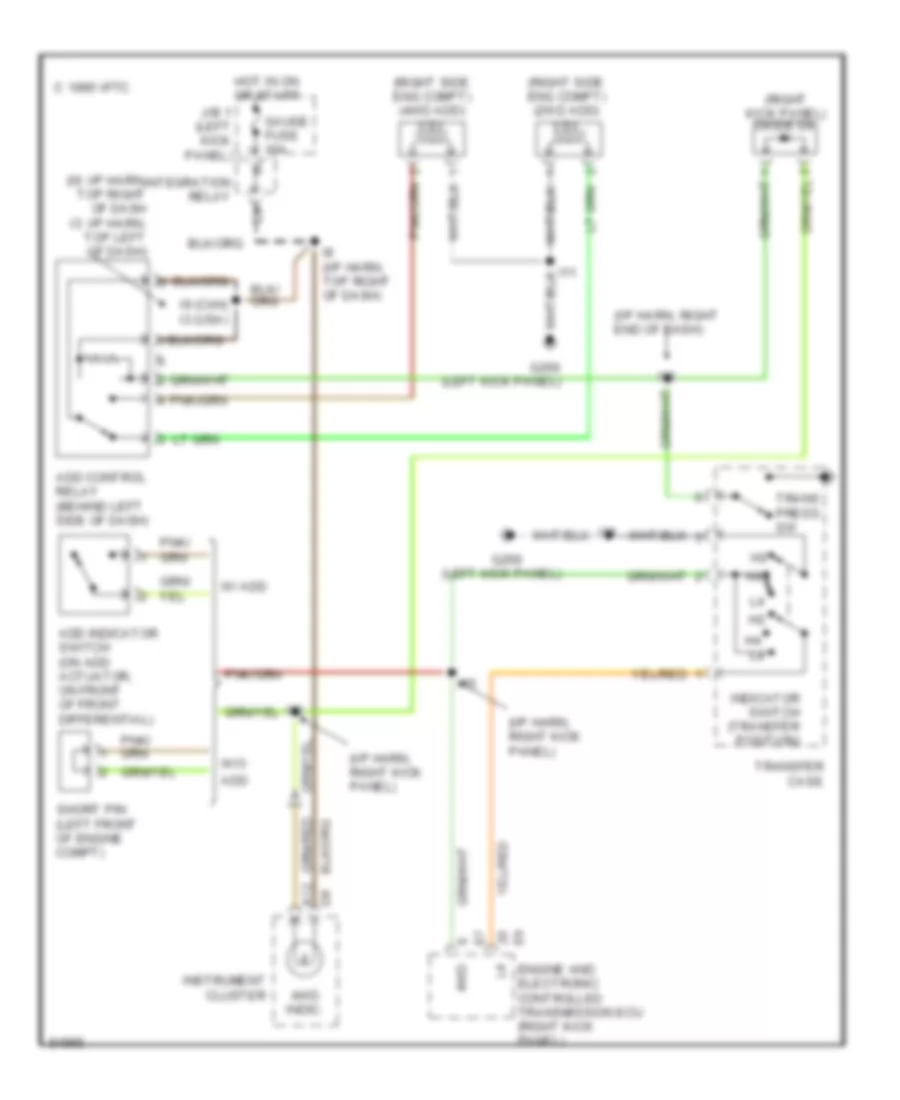
Transfer Case Wiring Diagram, M/T for Toyota Pickup DX 1995
List of elements for Transfer Case Wiring Diagram, M/T for Toyota Pickup DX 1995:
- (eng harn, right side of eng)
- (i/p harn, right kick panel)
- (i/p harn, right kick panel) i15
- (i9: i/p harn, top right side of dash i13: i/p harn, right end of dash)
- 2.4l
- 3.0l
- 4wd
- 4wd indic.
- A12
- Add control relay (left side of dash)
- Add indicator switch (front differential)
- C 1995 vftc
- E20
- Engine control module (right kick panel)
- G200 (left kick panel)
- Gauge fuse 10a
- Hot in on or start
- I11
- I13 (canada) i9 (usa)
- I15
- I9 (i/p harn, top right side of dash)
- Indicator switch (transfer position) (on transfer case)
- Instrument cluster
- Integration relay
- J/b 1 (left kick panel)
- Red
- Vsv v1 (2wd add) (right side eng compt)
- Vsv v2 (4wd add) (right side eng compt)
- W/ add
Transmission Wiring Diagram for Toyota Pickup DX 1995
List of elements for Transmission Wiring Diagram for Toyota Pickup DX 1995:
- (4wd)
- (column shift only)
- (console shft) (floor shft)
- (right kick panel)
- (right side of engine compt) e11
- (top center of dash)
- (top right side of dash) i9
- (top right side of engine) e12
- * w/ 2.4l engine
- ** *
- ** nca
- ** w/ 3.0l v6 engine
- ***
- *** 3.0l v6 w/ 4wd
- ****
- **** all 2.4l, 3.0l v6 w/ 2wd
- 4wd
- Batt
- C17
- Cig fuse 15a
- Cruise control system
- Data link connector 1 (right side eng compt)
- Dg te2 t e1
- Efi fuse 15a
- Efi main
- Electronic controlled transmission solenoid and vehicle speed sensor
- Engine and electronic controlled transmission ecu (right kick panel)
- Engine coolant temperature sensor (on intake manifold)
- Exterior lights
- G100 (front of left front fender)
- G117 (cam bearing cap)
- G120 (intake mani- fold)
- G201 (right side of i/p)
- Gauge fuse 10a
- Hot at all times
- Hot in acc or on
- Hot in on or start
- I15
- I15 (right kick panel)
- I15 (rt kick pnl)
- I4 (top center of dash)
- I6 i8 (center of dash)
- Idl
- Ign fuse 7.5a
- Indicator switch (transfer position)
- Indicator switch (transfer position) (on t-case)
- Instrument cluster system
- Integration relay
- Interior lights system
- Interior lights system (floor shift)
- J/b 1 (left kick panel)
- N **
- Nca
- Nca **
- No. 1
- No. 2
- No. 3
- No. 4
- Norm
- O/d main switch
- O/d off
- O/d relay (left side of dash)
- O/d solenoid (right rear of engine compt)
- Od1
- Od2
- Oil
- Oil temp
- Oil temperature sensor (right front trans pan)
- Park/neutral position switch (right side of transmission)
- Pattern select switch
- Pwr
- Pwr indic
- R/b 2 (right eng compt)
- Red
- Relay
- Sp1
- Sp2
- Speedo
- Sta
- Starting/ charging system
- Stop fuse 15a
- Stop light switch (above brake pedal)
- Stp
- Te2
- Th01
- Th02 te2
- Throttle position sensor (on throttle body)
- Thw
- Transfer case
- Transfer fluid temperature sensor
- Transfer pressure switch (for add)
- Transmissions systems (a/t transfer case circuit)
- Turn fuse 10a
- Vcc
- Vehicle speed sensor
- Vta
3.0L
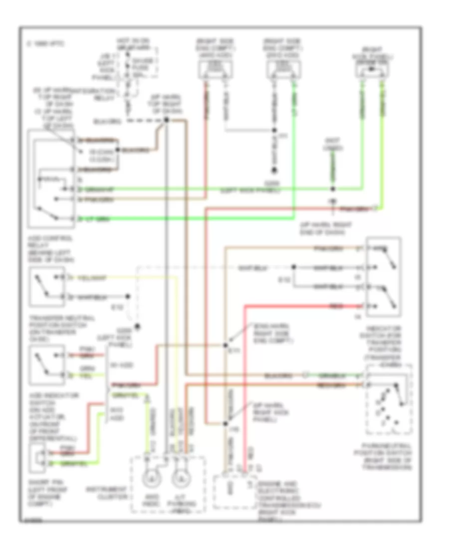
3.0L, Transfer Case Wiring Diagram, A/T for Toyota Pickup DX 1995
List of elements for 3.0L, Transfer Case Wiring Diagram, A/T for Toyota Pickup DX 1995:
- (i/p harn, right end of dash)
- (i/p harn, right kick panel)
- (i9: i/p harn, top right of dash i3: i/p harn, top left of dash)
- (left kick panel)
- (right kick panel) diode d6
- (right side eng compt) (2wd add) vsv
- (right side eng compt) (4wd add) vsv
- 1995 vftc c
- 4wd
- 4wd indic.
- A12
- Add
- Add control relay (behind left side of dash)
- Add indicator switch (on add actuator, on front of front differential)
- Engine and electronic controlled transmission ecu (right kick panel)
- G200
- G200 (left kick panel)
- Gauge fuse 10a
- Hot in on or start
- I11
- I13
- I15
- I9 (can) i3 (usa)
- I9 (i/p harn, top right of dash)
- Indicator switch (transfer position)
- Instrument cluster
- Integration relay
- J/b 1 (left kick panel)
- Short pin (left front of engine compt)
- Trans press sw
- Transfer case
- W/ add
- W/o
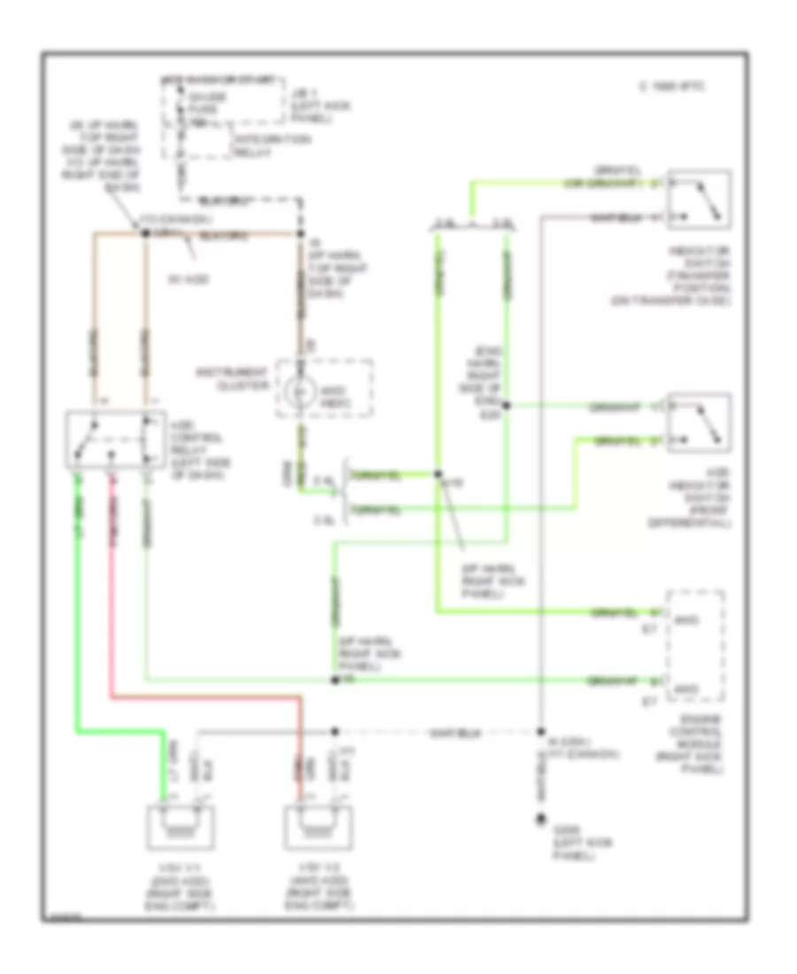
Transfer Case Wiring Diagram, M/T for Toyota Pickup DX 1995
List of elements for Transfer Case Wiring Diagram, M/T for Toyota Pickup DX 1995:
- (eng harn, right side of eng)
- (i/p harn, right kick panel)
- (i/p harn, right kick panel) i15
- (i9: i/p harn, top right side of dash i13: i/p harn, right end of dash)
- 2.4l
- 3.0l
- 4wd
- 4wd indic.
- A12
- Add control relay (left side of dash)
- Add indicator switch (front differential)
- C 1995 vftc
- E20
- Engine control module (right kick panel)
- G200 (left kick panel)
- Gauge fuse 10a
- Hot in on or start
- I11
- I13 (canada) i9 (usa)
- I15
- I9 (i/p harn, top right side of dash)
- Indicator switch (transfer position) (on transfer case)
- Instrument cluster
- Integration relay
- J/b 1 (left kick panel)
- Red
- Vsv v1 (2wd add) (right side eng compt)
- Vsv v2 (4wd add) (right side eng compt)
- W/ add
Transmission Wiring Diagram for Toyota Pickup DX 1995
List of elements for Transmission Wiring Diagram for Toyota Pickup DX 1995:
- (4wd)
- (column shift only)
- (console shft) (floor shft)
- (right kick panel)
- (right side of engine compt) e11
- (top center of dash)
- (top right side of dash) i9
- (top right side of engine) e12
- * w/ 2.4l engine
- ** *
- ** nca
- ** w/ 3.0l v6 engine
- ***
- *** 3.0l v6 w/ 4wd
- ****
- **** all 2.4l, 3.0l v6 w/ 2wd
- 4wd
- Batt
- C17
- Cig fuse 15a
- Cruise control system
- Data link connector 1 (right side eng compt)
- Dg te2 t e1
- Efi fuse 15a
- Efi main
- Electronic controlled transmission solenoid and vehicle speed sensor
- Engine and electronic controlled transmission ecu (right kick panel)
- Engine coolant temperature sensor (on intake manifold)
- Exterior lights
- G100 (front of left front fender)
- G117 (cam bearing cap)
- G120 (intake mani- fold)
- G201 (right side of i/p)
- Gauge fuse 10a
- Hot at all times
- Hot in acc or on
- Hot in on or start
- I15
- I15 (right kick panel)
- I15 (rt kick pnl)
- I4 (top center of dash)
- I6 i8 (center of dash)
- Idl
- Ign fuse 7.5a
- Indicator switch (transfer position)
- Indicator switch (transfer position) (on t-case)
- Instrument cluster system
- Integration relay
- Interior lights system
- Interior lights system (floor shift)
- J/b 1 (left kick panel)
- N **
- Nca
- Nca **
- No. 1
- No. 2
- No. 3
- No. 4
- Norm
- O/d main switch
- O/d off
- O/d relay (left side of dash)
- O/d solenoid (right rear of engine compt)
- Od1
- Od2
- Oil
- Oil temp
- Oil temperature sensor (right front trans pan)
- Park/neutral position switch (right side of transmission)
- Pattern select switch
- Pwr
- Pwr indic
- R/b 2 (right eng compt)
- Red
- Relay
- Sp1
- Sp2
- Speedo
- Sta
- Starting/ charging system
- Stop fuse 15a
- Stop light switch (above brake pedal)
- Stp
- Te2
- Th01
- Th02 te2
- Throttle position sensor (on throttle body)
- Thw
- Transfer case
- Transfer fluid temperature sensor
- Transfer pressure switch (for add)
- Transmissions systems (a/t transfer case circuit)
- Turn fuse 10a
- Vcc
- Vehicle speed sensor
- Vta
WARNING SYSTEMS
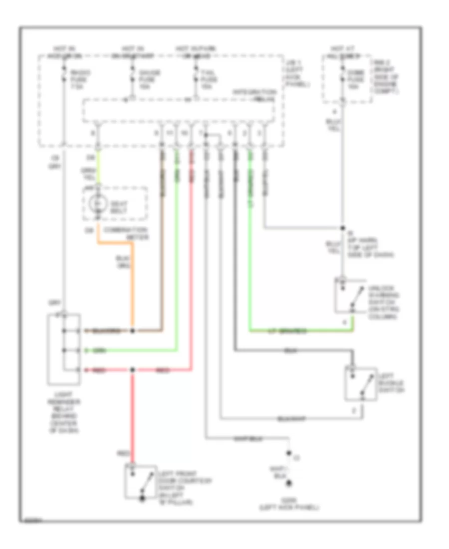
Warning System Wiring Diagrams for Toyota Pickup DX 1995
List of elements for Warning System Wiring Diagrams for Toyota Pickup DX 1995:
- Combination
- D10
- D11
- Dome fuse 10a
- G200 (left kick panel)
- Gauge fuse 10a
- Hot at all times
- Hot in acc or on
- Hot in on or start
- Hot in park or head
- I9 (i/p harn, top left side of dash)
- Integration
- J/b 1 (left kick panel)
- Left buckle switch
- Left front door courtesy switch (in left "b" pillar)
- Light reminder relay (behind center of dash)
- Meter
- R/b 2 (right side of engine compt)
- Radio fuse 7.5a
- Red
- Relay
- Seat belt
- Tail fuse 15a
- Unlock warning switch (on strg column)
WIPER/WASHER
Wiper/Washer Wiring Diagram for Toyota Pickup DX 1995
List of elements for Wiper/Washer Wiring Diagram for Toyota Pickup DX 1995:
- (i/p harness, top right end of dash) i11 (canada m/t)
- C15
- C16
- Combination switch
- G200 (left kick panel)
- High
- Hot in on or start
- I12 (except canada m/t) (i/p harness, right end of dash)
- I6 (except canada a/t) i3 (canada a/t)
- Int
- J/b 1 (left kick panel)
- Low/ mist
- Off
- Solid state
- Wash
- Washer motor (right front of engine compartment)
- Wiper fuse 20a
- Wiper motor (right rear of engine compartment)
- Wiper/ washer switch

 Čeština
 Dansk
Dansk Deutsch
 Ελληνικά
 English
 Español
 Suomi
Suomi Français
 Français
 עברית
עברית Hrvatski
 Magyar
 Italiano
 日本語
日本語 한국어
한국어 Nederlands
 Polski
 Português
 Português
 Română
 Русский
 Slovenčina
 Slovenščina
 Svenska
 Türkçe
 中文 (中国)