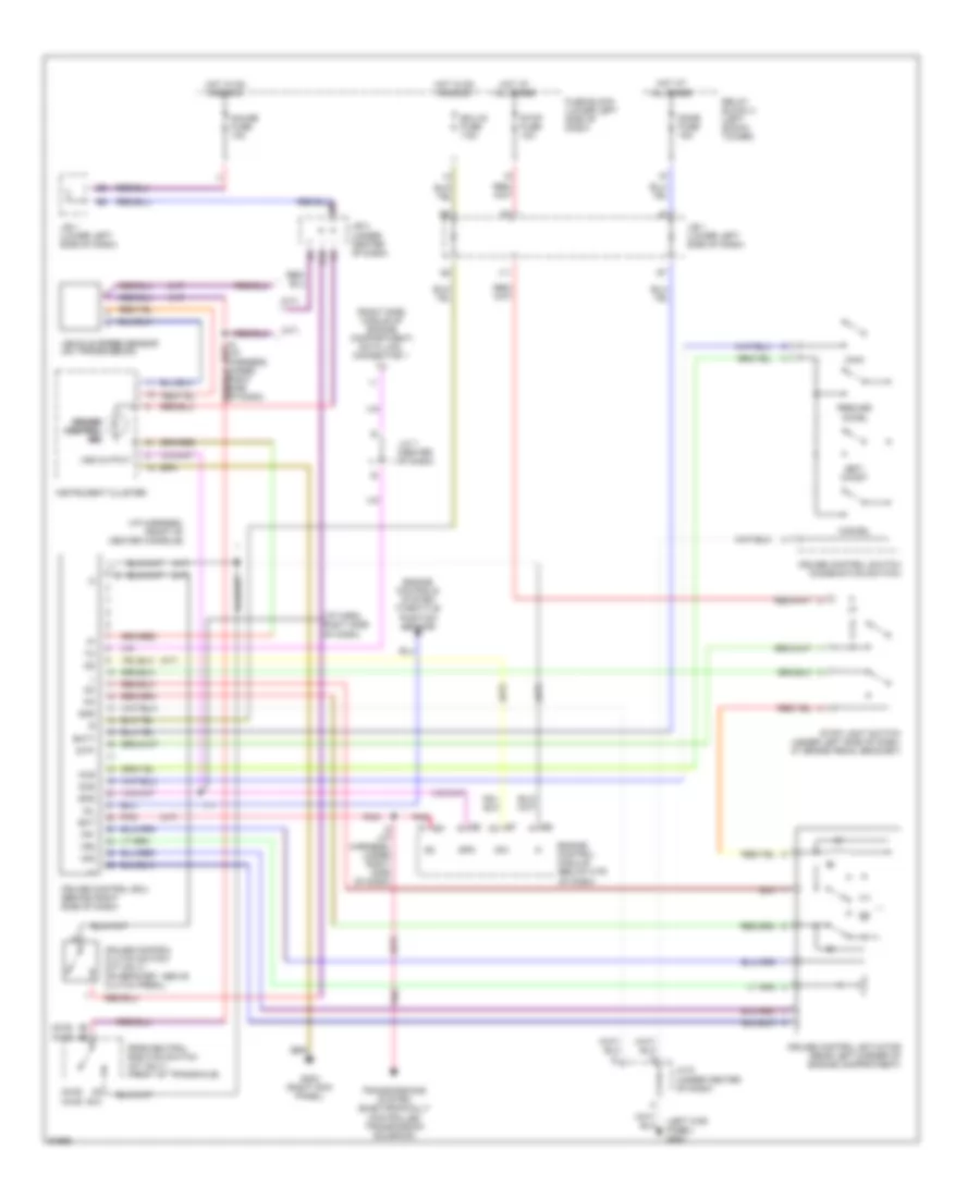
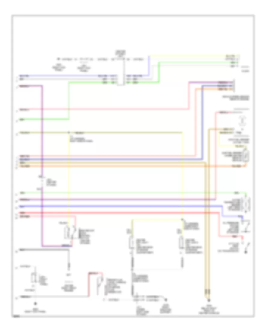
AIR CONDITIONING
A/C Wiring Diagram for Toyota RAV4 1997
 https://portal-diagnostov.com/license.html
Automotive Electricians Portal FZCO
Automotive Electricians Portal FZCO
https://portal-diagnostov.com/license.html
https://portal-diagnostov.com/license.html
Automotive Electricians Portal FZCO
Automotive Electricians Portal FZCO
List of elements for A/C Wiring Diagram for Toyota RAV4 1997:
- (engine room harn, front center of engine compt)
- (i/p harness, left side of i/p)
- (i/p harness, right side of i/p)
- (lower finish panel)
- A/c
- A/c amplifier (right side of i/p)
- A/c condenser fan relay
- A/c control switch
- A/c dual pressure switch (left front of engine compt)
- A/c fuse 7.5a
- A/c magnetic clutch and lock sensor
- A/c single pressure switch (left side of engine compt)
- A/c thermistor (behind right side of i/p)
- A/c water temp switch (behind center of front bumper)
- Ac1
- Act
- Alt fuse 100a
- Blower motor
- Blower resistor (right side of i/p)
- Blower switch
- Cds fan fuse 30a
- D14
- Defroster mode switch
- E/g main relay
- Ecu-ig fuse 7.5a
- Engine control module (behind front of center console)
- Fan relay
- Fuse block
- Fusible link block
- G108 (left side of radiator)
- G203 (right kick panel)
- Gauge fuse 10a
- Heater relay
- Hot at all times
- Hot in run or start
- Htr fuse 50a
- I11
- Ig+
- Ig-
- Igniter
- J/b (right kick panel)
- J/b 1
- J/b 3 (center of i/p)
- Junction connector
- Led+
- Mg/c relay
- Mgc
- Off
- R/b (left side of engine compt)
- R/b 2 (left side of engine compt)
- Radiator fan motor
- Rdi fan fuse 30a
- Ssr+
- Ssr-
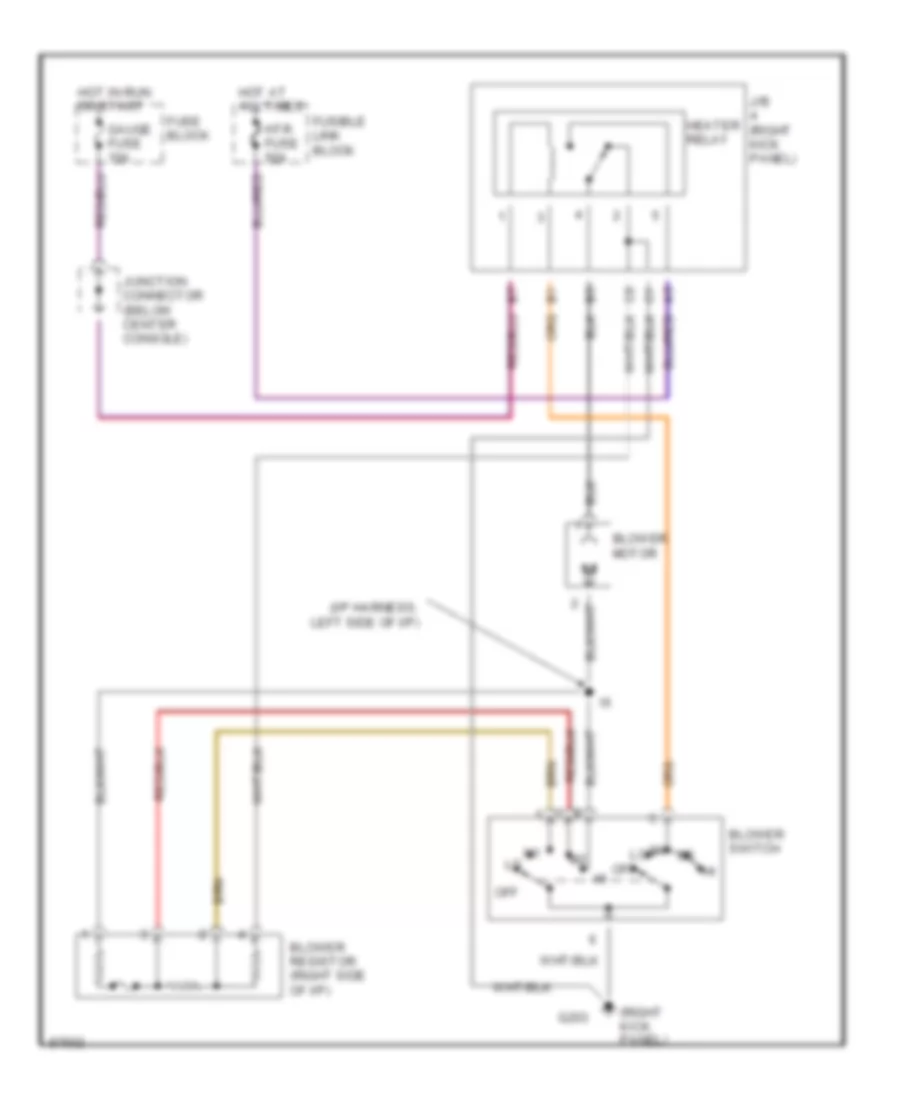
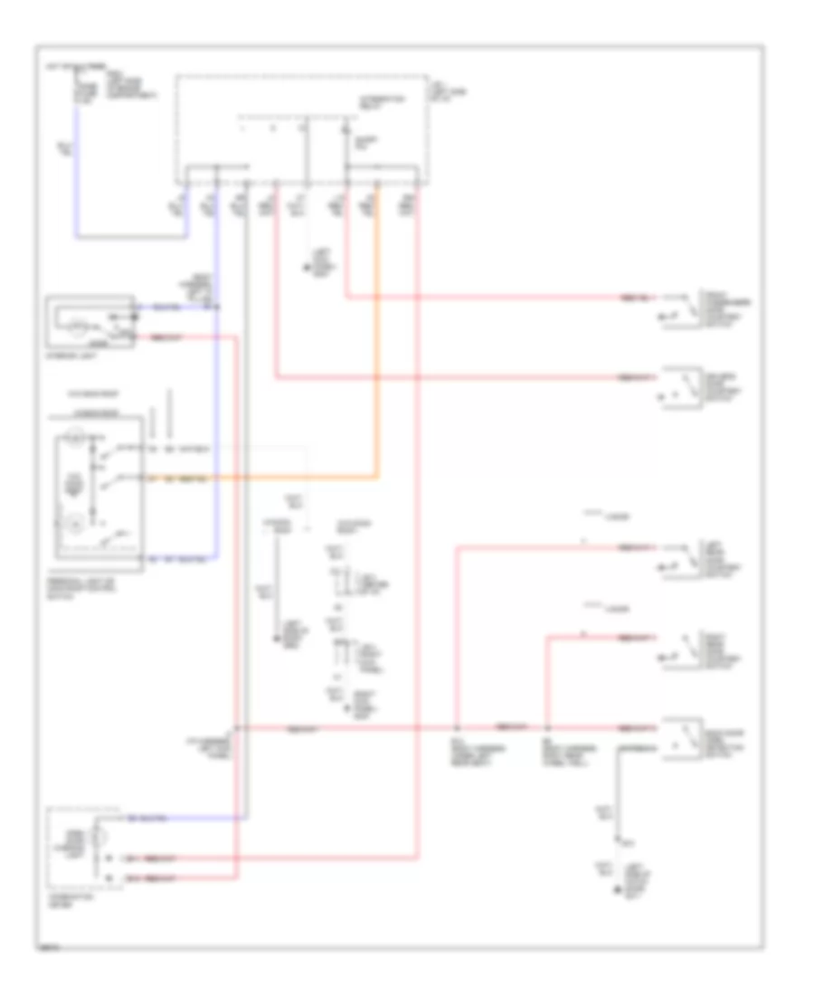
Heater Wiring Diagram for Toyota RAV4 1997
List of elements for Heater Wiring Diagram for Toyota RAV4 1997:
- (i/p harness, left side of i/p)
- (right kick panel)
- Blower motor
- Blower resistor (right side of i/p)
- Blower switch
- Fuse block
- Fusible link block
- G203
- Gauge fuse 10a
- Heater relay
- Hot at all times
- Hot in run or start
- Htr fuse 50a
- J/b (right kick panel)
- Junction connector (below center console)
- Off
ANTI-LOCK BRAKES
Anti-lock Brake Wiring Diagrams for Toyota RAV4 1997
List of elements for Anti-lock Brake Wiring Diagrams for Toyota RAV4 1997:
- (body harn, left front door sill)
- (eng harn, front of left front fender)
- (i/p harn, bottom left end of dash)
- (left radiator support)
- (right side of engine compt) abs actuator
- +ig
- 2 door
- 4 door
- 4 door w/ 4wd only
- 4wd (2 door)
- A10
- A11
- A12
- Abs deceleration sensor (4wd only) (left side of i/p, near accelerator) (4wd only) abs deceleration sensor
- Abs ecu (left side of i/p)
- Abs fuse 60a
- Abs relay (left front of engine compt)
- Abs warning ind
- All others
- Ast
- B10
- B11
- B12
- B13
- B14
- B15
- B16
- B17
- B18
- B19
- B20
- B21
- B22
- B23
- B24
- B25
- B26
- Combination meter
- Data link connector 1 (right side of engine compt)
- E1 (engine harn, behind right side of radiator)
- Ecu-ig fuse 7.5a
- Fl+
- Fl-
- Fr+
- Fr-
- Fuse block (left side of steering column)
- G108
- G108 (left radiator support)
- Gauge fuse 10a
- Ggnd
- Gl1
- Gl2
- Gnd
- Gs2
- Gsi
- Gst
- Hot at all times
- Hot in on
- I13
- I14
- Ig1
- J/b 1 (left side of steer- ing column)
- J/b 1 (left side of steering column)
- J/b 3 (center of dash)
- Left front abs speed sensor
- Left rear abs speed sensor
- Nca
- R/b 2 (left front shock tower)
- Red
- Right front abs speed sensor
- Right rear abs speed sensor
- Rl+
- Rl-
- Rr+
- Rr-
- Sflh
- Sflr
- Sfrh
- Sfrr
- Shield
- Srlh
- Srlr
- Srrh
- Srrr
- Stop fuse 10a
- Stop light switch
- Stp
- Vgs
COMPUTER DATA LINES
Computer Data Lines for Toyota RAV4 1997
List of elements for Computer Data Lines for Toyota RAV4 1997:
- (4wd, 2 dr) b21
- (exp 4wd, 2 dr) a8
- Abs ecu (near left kick panel)
- Abs ind
- Abs relay (on left front of engine compt, behind radiator)
- Airbag sensor assembly (under center console)
- B11
- Circuit opening relay
- Combination meter
- Cruise control ecu (behind right side of dash)
- Data link connector 1 (on right side, middle of engine compt)
- Data link connector 3 (under center, bat
- Ea1 connector (on r/b 2)
- Efi main relay
- Engine control module (under center of dash)
- Engine controls system
- Fuse block (on lower left side of dash)
- G117 (right rear of engine)
- G203 (right kick panel)
- Gauge fuse 10a
- Hot at all times
- Hot in on or start
- I11 (i/p harness, behind center of dash, below radio)
- I4 (i/p harness, below center console)
- I6 (i/p harness, (below left end of dash)
- J/b 1 (on lower left side of dash)
- J/c 10/ j/c 11 (left side of center console)
- J/c 2 (front of center console)
- J/c 7 (behind combination meter)
- Left side of dash)
- Obd fuse 7.5a
- R/b 6 (left front strut tower)
- Sdl
- Shield
- Srs fuse 7.5a
- Srs ind
- Te1
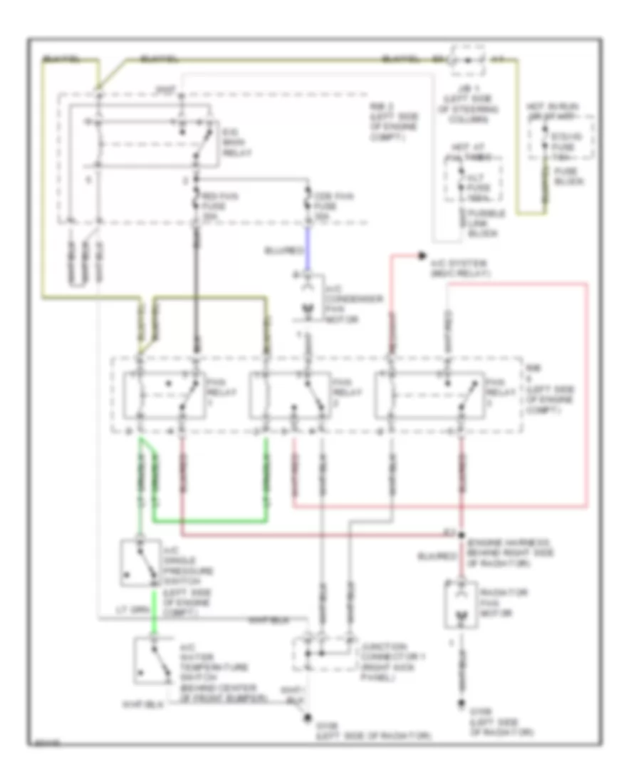
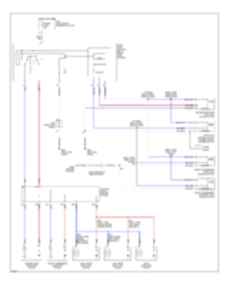
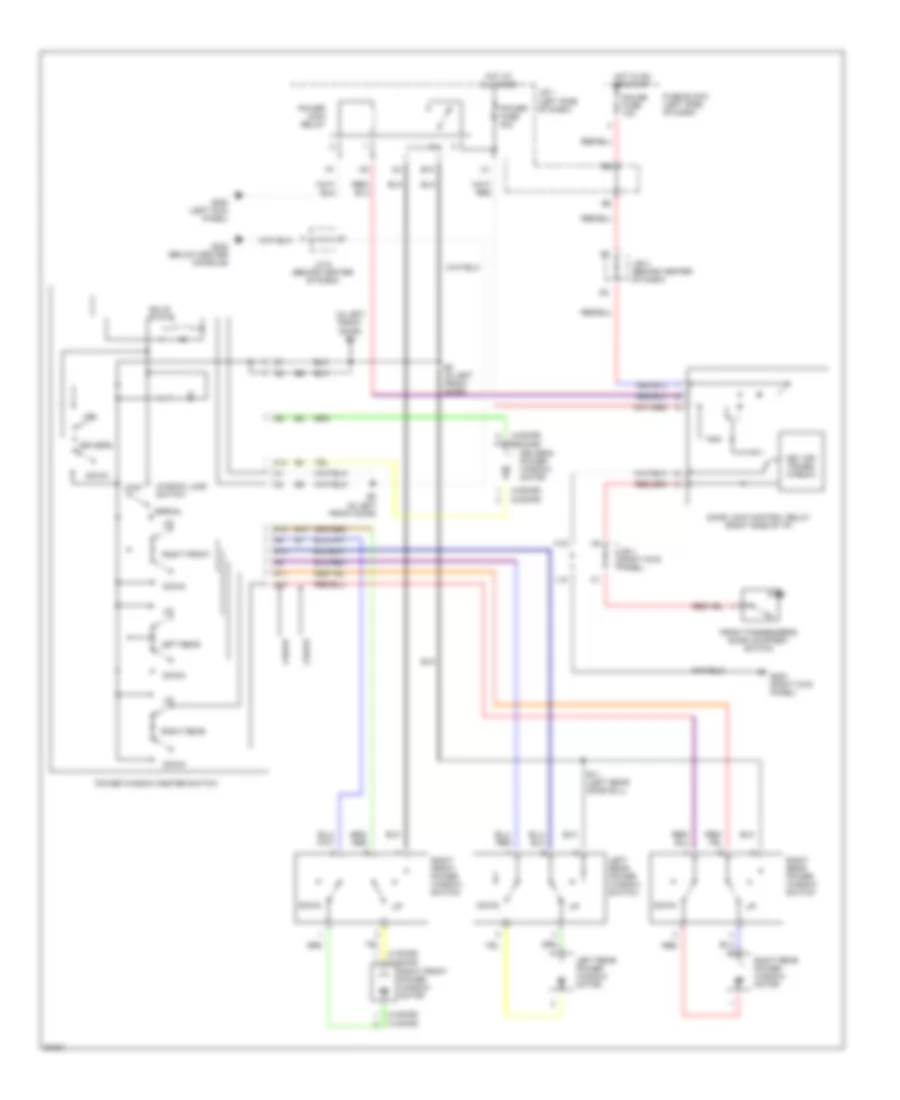
COOLING FAN
Cooling Fan Wiring Diagram for Toyota RAV4 1997
List of elements for Cooling Fan Wiring Diagram for Toyota RAV4 1997:
- A/c condenser fan motor
- A/c single pressure switch (left side of engine compt)
- A/c system (mg/c relay)
- A/c water temperature switch (behind center of front bumper)
- Alt fuse 100a
- Cds fan fuse 30a
- E/g main relay
- Ecu-ig fuse 7.5a
- Fan relay
- Fuse block
- G108 (left side of radiator)
- Hot at all times
- Hot in run or start
- J/b 1 (left side of steering column)
- Junction connector 1 (right kick panel)
- Of radiator)
- R/b (left side of engine compt)
- R/b 2 (left side of engine compt)
- Radiator fan motor
- Rdi fan fuse 30a
CRUISE CONTROL
Cruise Control Wiring Diagram for Toyota RAV4 1997
List of elements for Cruise Control Wiring Diagram for Toyota RAV4 1997:
- (2wd)
- (4wd)
- (a/t)
- (i/p harn, right side of dash)
- (i/p harness, front of center console)
- (i/p harness, under right side of dash)
- (left kick panel) g200
- (m/t)
- (right side, middle of engine compartment) data link connector 1
- (under center of dash)
- B10
- B18
- Batt
- Cancel
- Ccs
- Cms
- Cruise control actuator (rear left corner of engine compartment)
- Cruise control clutch switch (m/t only) (on bracket, above clutch pedal)
- Cruise control ecu (behind right side of dash)
- Cruise control switch (combination switch)
- Cruise cruise cruise control control control ind ind ind
- Dome fuse 15a
- Ect
- Ecu-ig fuse 7.5a
- Engine control module (below ctr of dash)
- Engine controls system (throttle position sensor)
- Fuse block (lower left side of dash)
- G203 (right kick panel)
- Gauge fuse 10a
- Gnd
- Hot at all times
- Hot in on and acc
- I11
- Idl
- Instrument cluster
- J/b 1 (lower left side of dash)
- J/b 3 (under center of dash)
- J/c 6
- J/c 7 (center of dash)
- Main
- Od1
- Park/neutral position switch (a/t only) (front of transaxle)
- Pnk
- Relay block 2 (left shock tower)
- Resume/ accel
- Set/ coast
- Spd
- Stop fuse 10a
- Stop light switch (under left side of dash, at brake pedal bracket)
- Stp-
- Transmissions system (electronically controlled transmission solenoid)
- Vehicle speed sensor (on transmission)
- Vr1
- Vr2
- Vr3
- Vss output
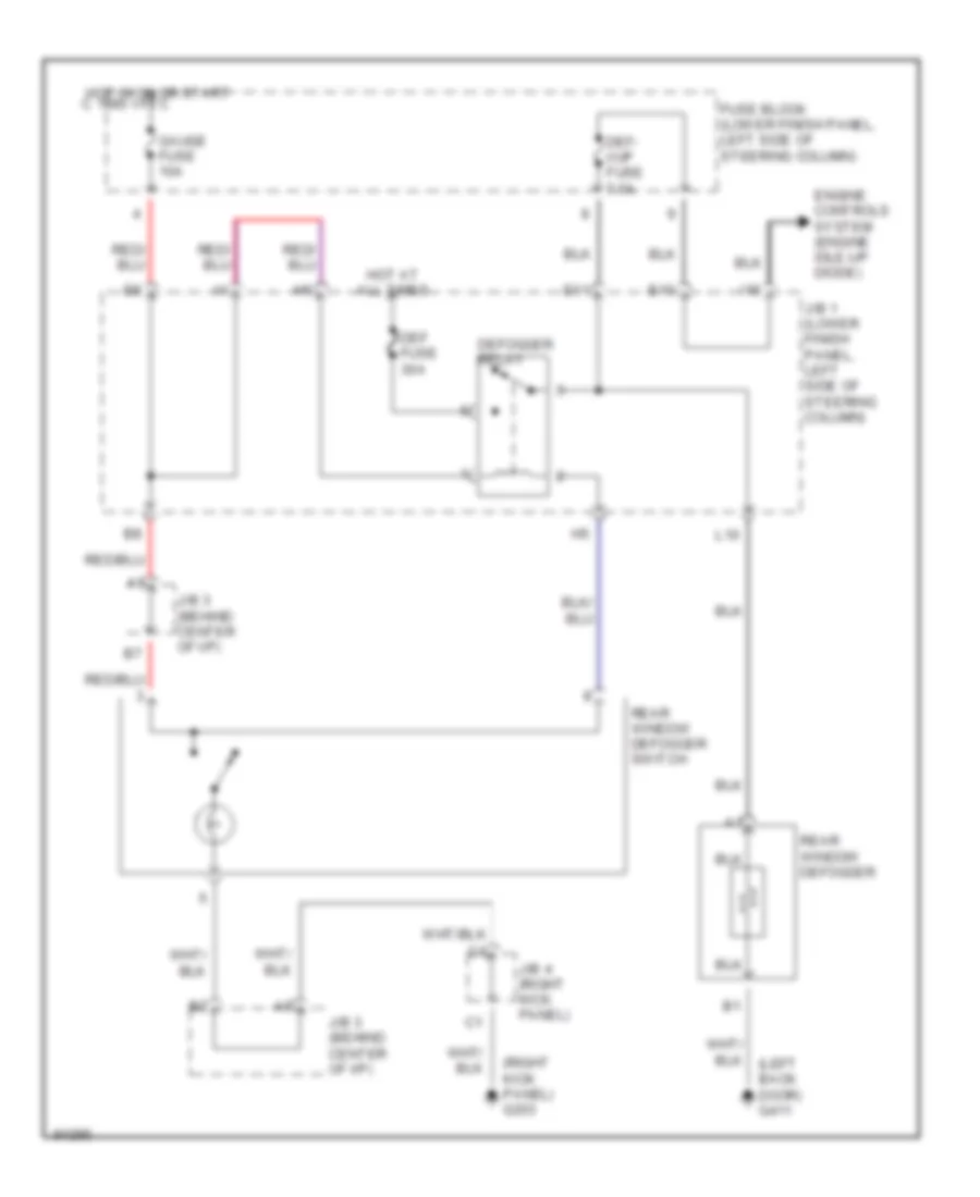
DEFOGGERS
Defogger Wiring Diagram for Toyota RAV4 1997
List of elements for Defogger Wiring Diagram for Toyota RAV4 1997:
- (right kick panel) g203
- C 1995 vftc
- Def fuse 30a
- Def- i/up fuse 7.5a
- Defogger relay
- E10
- E11
- Engine controls system (engine idle-up diode)
- Fuse block (lower finish panel, left side of steering column)
- Gauge fuse 10a
- Hot at all times
- Hot in on or start
- I15
- J/b 1 (lower finish panel, left side of steering column)
- J/b 3 (behind center of i/p)
- J/b 4 (right kick panel)
- L10
- Rear window defogger
- Rear window defogger switch
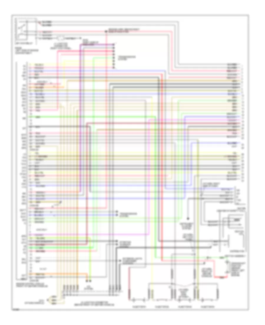
ENGINE PERFORMANCE
2.0L
2.0L, Engine Performance Wiring Diagrams (1 of 2) for Toyota RAV4 1997
List of elements for 2.0L, Engine Performance Wiring Diagrams (1 of 2) for Toyota RAV4 1997:
- #10
- #20
- #30
- #40
- (engine harn, behind right e1 side of radiator)
- (i/p harn, front of center console)
- (i/p harn, left kick panel)
- (i/p harn, right side of dash)
- 4wd only
- A/c system
- Ac1
- Act
- B/k
- Batt
- Conn e4
- Conn e5
- Conn e6
- Crankshaft position sensor (front left side of engine)
- Distributor
- Efi main relay
- Egr
- Els
- Engine control module (front of center console)
- Eo1
- Eo2
- Eo3
- Evp
- Exterior lights & defogger systems
- Fr+
- Fr-
- G109 (right side of radiator)
- G131 (intake manifold)
- Igf
- Igniter (center of safety wall)
- Ignition assembly
- Ignition coil
- Igt
- Injector #1
- Injector #2
- Injector #3
- Injector #4
- Instrument cluster system
- Iscc
- Isco
- J1 junction connector (right kick panel)
- J2 junction connector (behind front of center console)
- Knk
- Nca
- Ne+
- Ne-
- New
- Ox1
- Ox2
- Pim
- Pnk
- Ptnk
- R/b #6 (left side of engine compartment)
- Red
- Rr+
- Rr-
- Sdl
- Sld+
- Sld-
- Spd
- Sta
- Starting/ charging system
- Tac
- Te1
- Tha
- Thw
- Tpc
- Transmissions system
- Vta
- W/ a/t
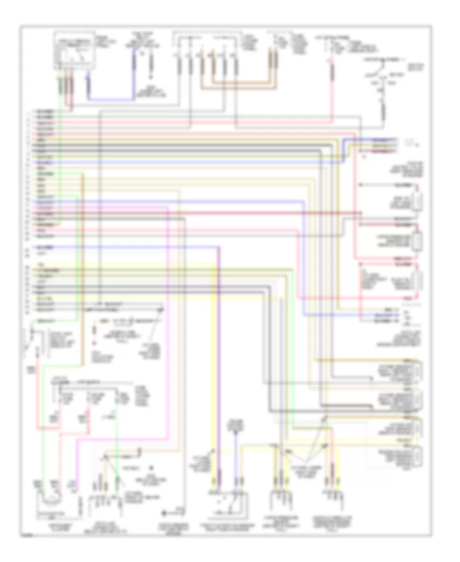
2.0L, Engine Performance Wiring Diagrams (2 of 2) for Toyota RAV4 1997
List of elements for 2.0L, Engine Performance Wiring Diagrams (2 of 2) for Toyota RAV4 1997:
- (i/p harn, (front of center console)
- (i/p harn, under right side of dash)
- (left kick panel)
- Acc
- Bat
- Circuit opening relay
- Cruise control system
- Data link connector 1 (right side of engine compartment)
- Data link connector 3 (below center of i/p)
- Efi fuse 15a
- Egr vsv (left side of engine)
- Engine coolant temp sensor (left side of engine)
- Evap vsv (rear of engine)
- Fuel pump relay (below left rear of vehicle)
- Fuse block (lower finish panel)
- G131 (on intake manifold)
- G302 (below center of dash)
- G308 (under left center pillar)
- Gauge fuse 10a
- Hot at all times
- Hot in run
- I5 (i/p harn, (lower right side of dash)
- I5 (i/p harn, lower right side of dash)
- Idle air control valve (right rear side of engine)
- Ig2
- Ign fuse 7.5a
- Ignition switch
- Instrument cluster
- Intake air temp sensor (rear of engine)
- J/b #1 (lower finish panel)
- Knock sensor (top center of engine)
- Lock
- Malfunction ind
- Manifold absolute pressure sensor (center of safety wall)
- Nca
- Noise filter (center of safety wall)
- Obd fuse 7.5a
- Oxygen sensor bank 1 sensor 1 (rear left side of engine)
- Oxygen sensor bank 1 sensor 2 (rear left side of engine)
- Pim
- Pnk
- Ptnk
- R/b #2 (left side of engine compt)
- R/b #5 (left kick panel)
- Run
- Sdl
- Start
- Stop fuse 10a
- Stop light switch (below left side of i/p)
- Te1
- Throttle position sensor (right side of engine)
- Vapor pressure sensor (center of safety wall)
- Vapor pressure sensor vsv (rear of engine)
- Vcc
- Vss input
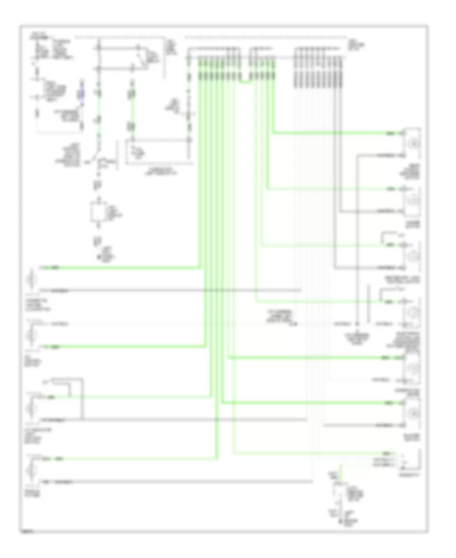
EXTERIOR LIGHTS
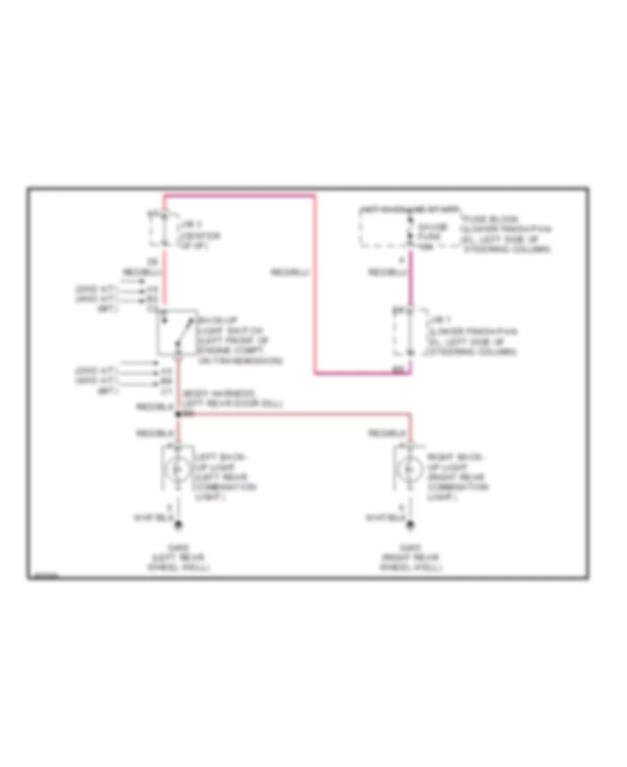
Back-up Lamps Wiring Diagram for Toyota RAV4 1997
List of elements for Back-up Lamps Wiring Diagram for Toyota RAV4 1997:
- (2wd a/t) (4wd a/t) (m/t)
- (center of i/p)
- (lower finish pan- el, left side of steering column)
- A6 b2 c2
- Back-up light switch (left front of engine compt, on transmission)
- Fuse block (lower finish pan- el, left side of steering column)
- G402 (left rear wheel well)
- G403 (right rear wheel well)
- Gauge fuse 10a
- Hot in on and start
- J/b 1
- J/b 3
- Left back- up light (left rear combination light)
- Right back- up light (right rear combination light)
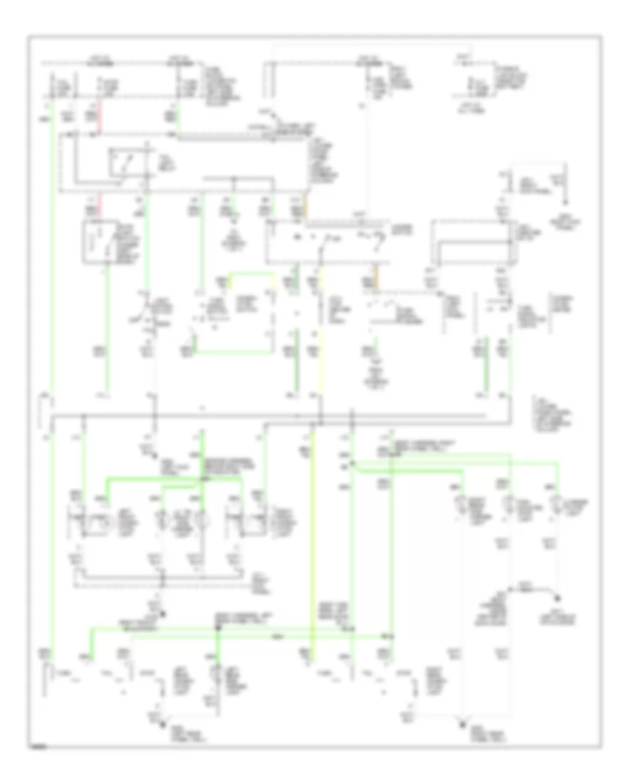
Exterior Lamps Wiring Diagram for Toyota RAV4 1997
List of elements for Exterior Lamps Wiring Diagram for Toyota RAV4 1997:
- (body har- ness, left rear door sill) b5
- (body harness, left rear wheel well) b6
- (engine harness, behind right side of radiator) e1
- Alt fuse 100a
- B10 (body harness, inside center of back door)
- C10
- Combin- ation meter
- Combin- ation switch
- D20
- E17
- From j/b 1 (diagram 1 of 1)
- Fuse block (lower fin- ish panel, left side of steering column)
- Fusible link block (near the battery)
- G109 (right radiat- or support)
- G200 (left kick panel)
- G203 (right kick panel)
- G402 (left rear wheel well)
- G403 (right rear wheel well)
- G411 (left side of hatch door)
- Haz- horn fuse 15a
- Hazard switch
- Head
- High mounted stop light
- Hot at all times
- I11
- I13
- J/b 1 (lower finish panel, left side of steering column)
- J/b 3 (center of i/p)
- J/b 4 (right kick panel)
- J/c 1 (right kick panel)
- J/c 4 (top center of dash)
- J14
- L12
- L14
- Left front combin- ation light
- Left rear combin- ation light
- Left rear side marker light
- Lh rh front side marker light
- License plate light
- Light control switch
- Off
- Park
- R/b 2 (left shock tower)
- R/b 5 (left kick panel)
- Right front combin- ation light
- Right rear combin- ation light
- Right rear side marker light
- Side of dash)
- Stop
- Stop fuse 10a
- Stop light switch (under left side of dash)
- Tail
- Tail fuse 10a
- Tail light relay
- To r/b 5 (diagram 1 of 1)
- Turn
- Turn fuse 7.5a
- Turn signal flasher
- Turn signal indicator lights
- Turn signal switch
GROUND DISTRIBUTION
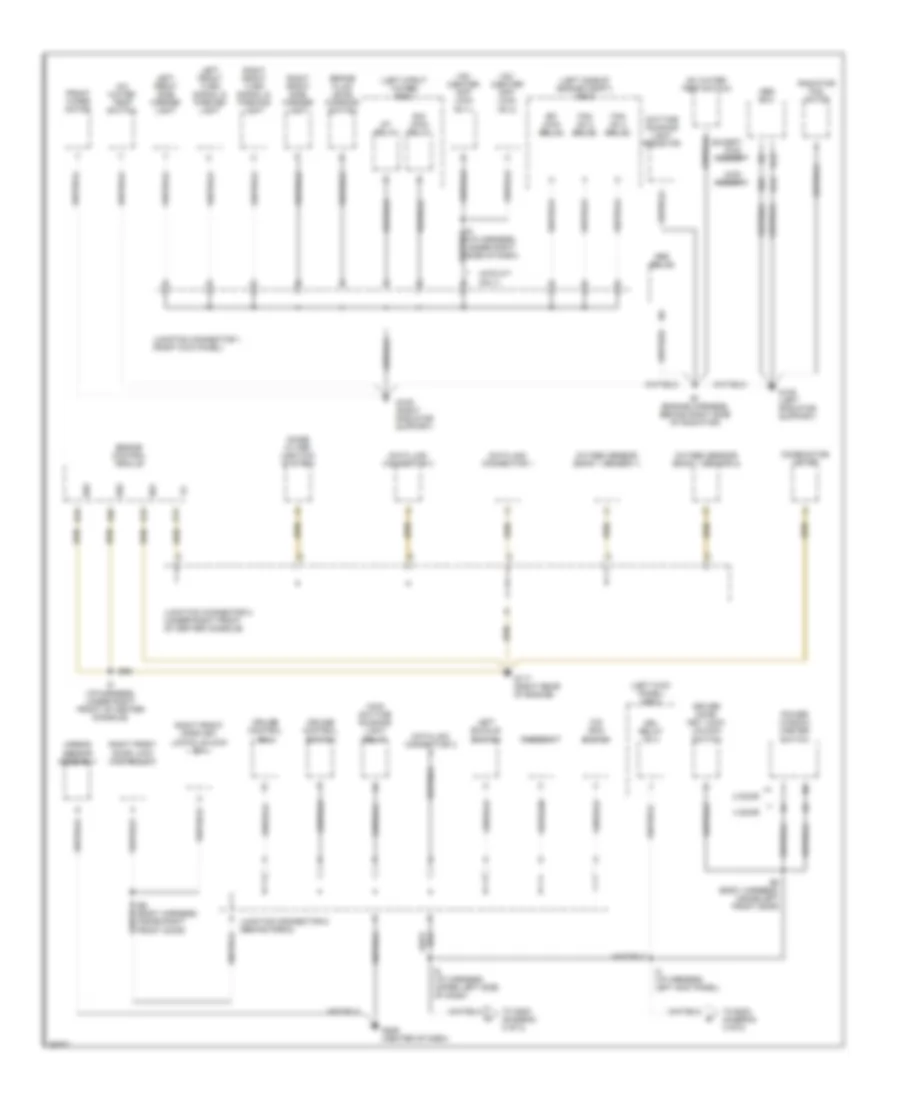
Ground Distribution Wiring Diagram (1 of 2) for Toyota RAV4 1997
List of elements for Ground Distribution Wiring Diagram (1 of 2) for Toyota RAV4 1997:
- (4wd m/t only)
- (left kick panel) r/b 5
- (left side of engine compt) r/b 6
- (left strut tower) r/b 2
- 2 door
- 4 door
- 4wd- 2 door
- A/c water temp switch
- A13
- A14
- A26
- Abs ecu
- Abs relay
- Airbag sensor assembly
- B12
- B13
- B16
- B2 (body harness, inside left front door)
- B25
- B8 (body harness, inside right front door)
- Brake fluid level warning switch
- Combination meter
- Cruise control ecu
- Cruise control switch
- Data link connector 1
- Data link connector 3
- Daytime running light resistor
- Driver door key lock/ unlock switch
- Drl relay no 4
- E/g main relay
- E01
- E02
- E03
- E1 (engine harness, behind right side of radiator)
- Efi main relay
- Engine control module
- Except 4wd- 2 door
- Fan no 2 relay
- Fan no 3 relay
- Front wiper motor
- G108 (left radiator support)
- G109 (right radiator support)
- G117 (right rear of engine)
- G206 (center of dash)
- I2 (i/p harness, left kick panel)
- I5 (i/p harness, under right front of center console)
- I5 (i/p harness, under right side of dash)
- I6 (i/p harness, upper left side of dash)
- Junction connector 1 (right kick panel)
- Junction connector 2 (under right front of center console)
- Junction connector 6 (behind radio)
- Left buckle switch
- Left front side marker light
- Left front turn signal & parking light
- Main daytime running light relay
- Noise filter (ignition system)
- O/d main switch
- Oxygen sensor (bank 1 sensor 1)
- Oxygen sensor (bank 1 sensor 2)
- Power window master switch
- Radiator fan motor
- Rheostat
- Right front door key lock & unlock sw
- Right front door lock control sw
- Right front side marker light
- Right front turn signal & parking light
- St relay
- To g200 (diagram 2 of 2)
- To g203 (diagram 2 of 2)
- Vsv (center diff lock no 1)
- Vsv (center diff lock no 2)
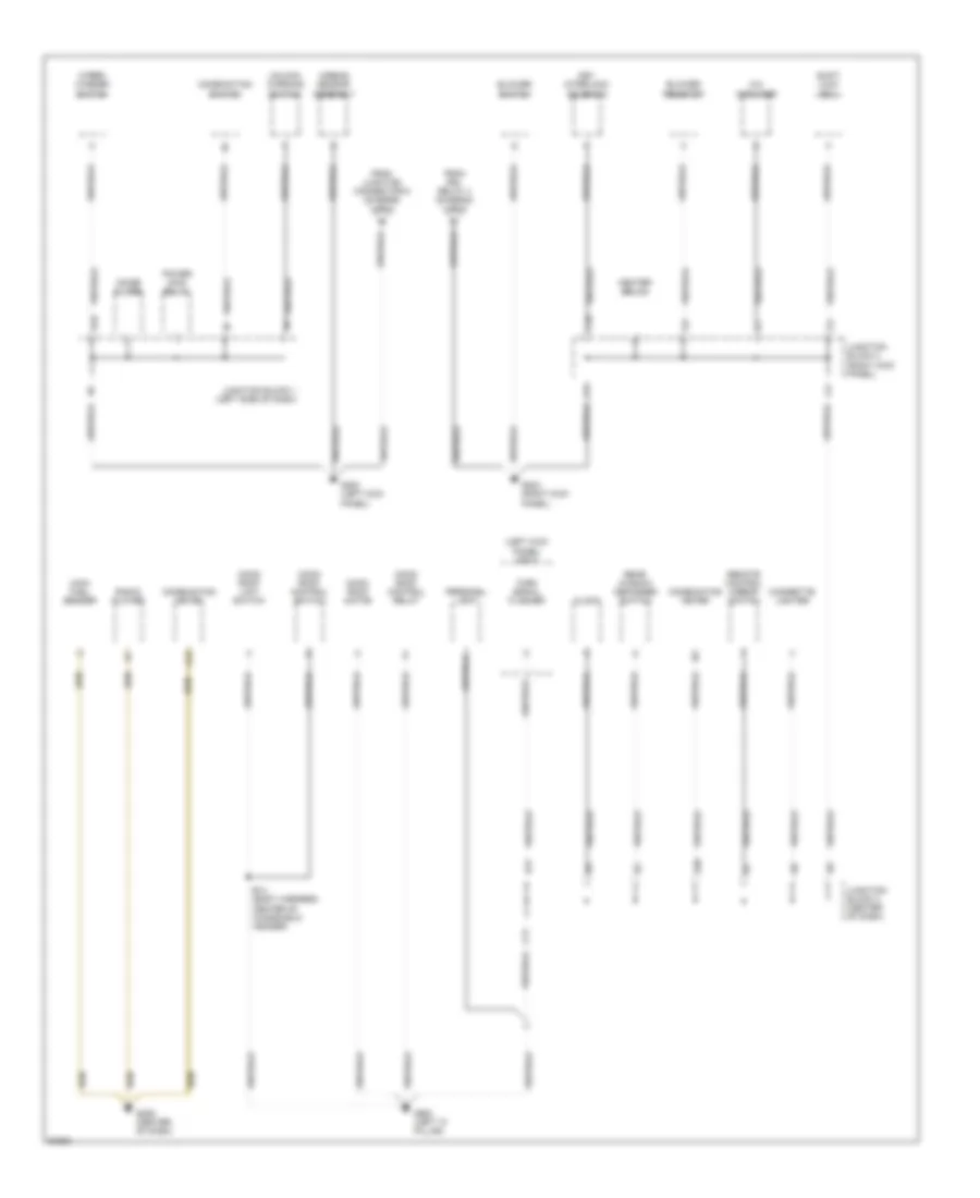
Ground Distribution Wiring Diagram (2 of 2) for Toyota RAV4 1997
List of elements for Ground Distribution Wiring Diagram (2 of 2) for Toyota RAV4 1997:
- (left kick panel) r/b 5
- A/c amplifier
- A12
- Airbag sensor assembly
- B14 (body harness, center of windshield header)
- Blower resistor
- Blower switch
- C10
- C11
- Cigarette lighter
- Clock
- Combination meter
- Combination switch
- D20
- E17
- From drl relay 4 (diagram 1 of 2)
- From junction connector 6 (diagram 1 of 2)
- G200 (left kick panel)
- G203 (right kick panel)
- G206 (center of dash)
- G900 (left "a" pillar)
- H16
- Heater relay
- Junction block 1 (left side of dash)
- Junction block 3 (center of dash)
- Junction block 4 (right kick panel)
- Key interlock solenoid
- Main fuel sender
- Moon roof control relay
- Moon roof control switch
- Moon roof limit switch
- Moon roof motor
- Noise filter
- Personal light
- Power main relay
- Radio/ player
- Rear window defogger switch
- Remote control mirror switch
- Shift lock ecu
- Turn signal flasher
- Unlock warning switch
- Wiper/ washer switch
HEADLIGHTS
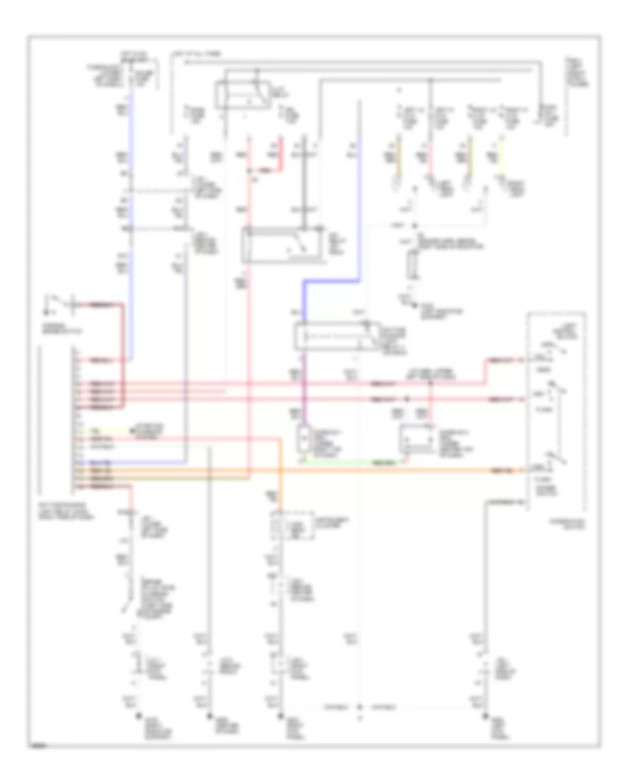
Headlight Wiring Diagram, with DRL for Toyota RAV4 1997
List of elements for Headlight Wiring Diagram, with DRL for Toyota RAV4 1997:
- (i/p harn, upper left side of dash) i6
- A10
- B19
- Brake fluid level warning switch (left side of engine compt)
- Combination switch
- Control
- D20
- Daytime running light relay (main) (right side of dash)
- Daytime running light relay 4 (on r/b 5)
- Dim relay (on r/b 6)
- Dimmer switch
- Diode no 1 (drl) (under right top of dash)
- Diode no 2 (drl) (under center top of dash)
- Dome fuse 15a
- Drl fuse 7.5a
- E12
- Flash
- Fuse block (lower left side of dash)
- G108 (left radiator support)
- G109 (right radiator support)
- G200 (left kick panel)
- G203 (right kick panel)
- G206 (center of dash)
- Gauge fuse 10a
- H-lp relay
- Head
- High
- High beam ind
- Hot at all times
- Hot in on or start
- I22
- Instrument cluster
- J/b 1 (left side of dash)
- J/b 1 (lower left side of dash)
- J/b 3 (behind center of dash)
- J/b 4 (right kick panel)
- J/c 1 (right kick panel)
- J/c 6 (behind radio)
- J15
- Left head- light
- Left hi h-lp fuse 10a
- Left lo h-lp fuse 10a
- Light
- Main no 1 fuse 30a
- Off
- Parking brake switch
- R/b 2 (left front strut tower)
- Red
- Right head- light
- Right hi h-lp fuse 10a
- Right lo h-lp fuse 10a
- Right side of radiator)
- Starting/ charging system
- Switch
- Tail
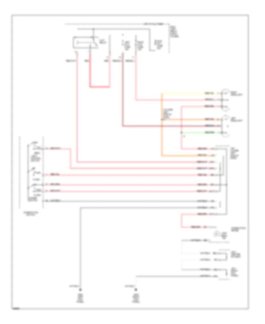
Headlight Wiring Diagram, without DRL for Toyota RAV4 1997
List of elements for Headlight Wiring Diagram, without DRL for Toyota RAV4 1997:
- (i/p harn, left side of dash) i3
- C14
- Combination meter
- Combination switch
- D20
- Dimmer switch
- Flash
- G10
- G11
- G200 (left kick panel)
- G203 (right kick panel)
- H-lp relay
- Head
- High
- High beam ind
- Hot at all times
- J/b 1 (lower left side of dash)
- J/b 3 (center of dash)
- J/b 4 (right kck panel)
- J10
- Left h-lp fuse 15a
- Left headlight
- Light control switch
- Main no 1 fuse 30a
- Off
- R/b 2 (left front strut tower)
- Red
- Right h-lp fuse 15a
- Right headlight
- Tail
HORN
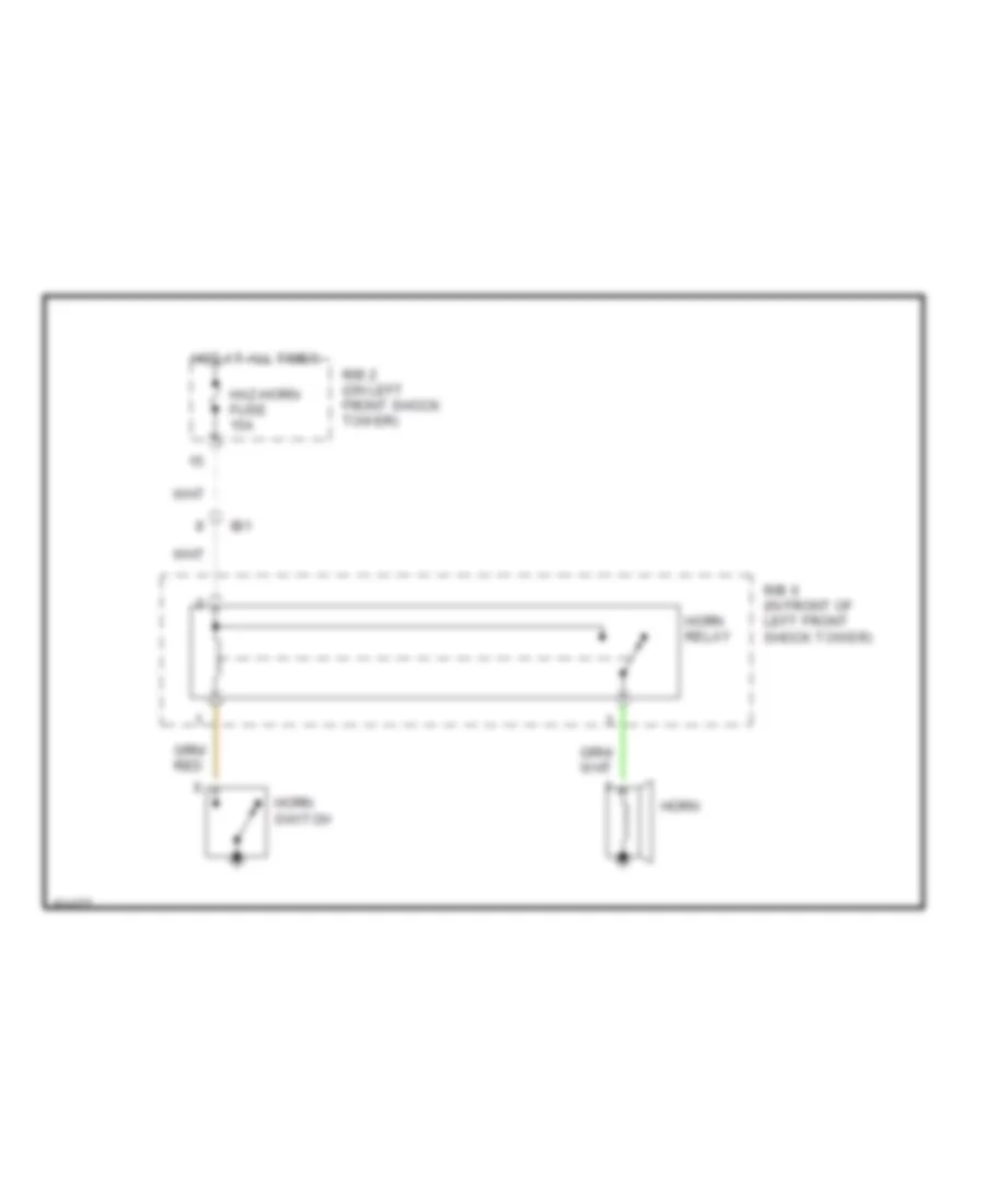
Horn Wiring Diagram for Toyota RAV4 1997
List of elements for Horn Wiring Diagram for Toyota RAV4 1997:
- Haz-horn fuse 15a
- Horn
- Horn relay
- Horn switch
- Hot at all times
- Ib1
- R/b 2 (on left front shock tower)
- R/b 6 (in front of left front shock tower)
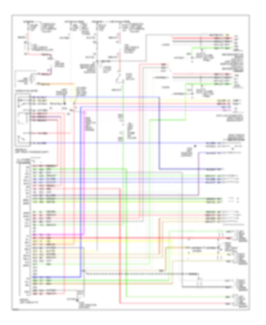
INSTRUMENT CLUSTER
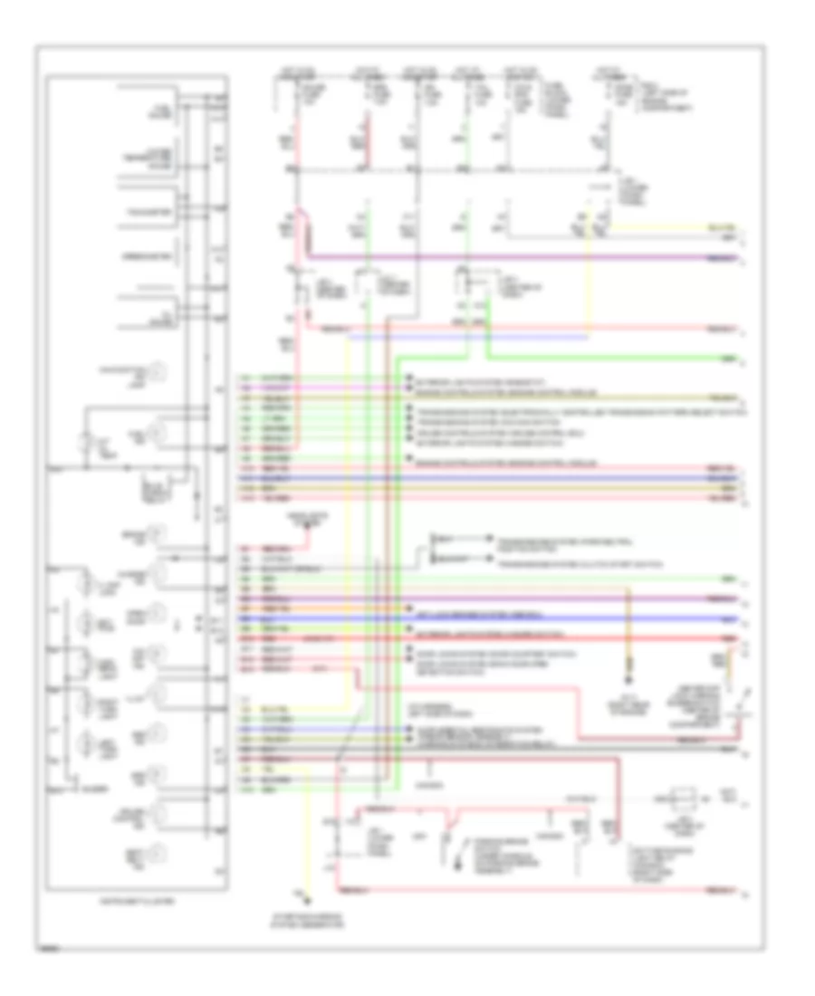
Instrument Cluster Wiring Diagram (1 of 2) for Toyota RAV4 1997
List of elements for Instrument Cluster Wiring Diagram (1 of 2) for Toyota RAV4 1997:
- (4wd a/t)
- (i/p harness, left side of dash)
- (left side of engine compartment)
- (m/t)
- A/t
- A/t oil temp
- A10
- A11
- A12
- A13
- Abs ind
- Anti-lock brakes system (abs ecu)
- B10
- B11
- B12
- B13
- B19
- Brake ind
- Bulb check relay
- Buzzer
- C. diff lock
- C10
- C11
- Canada
- Center diff lock warning buzzer switch (center of engine compartment)
- Charge ind
- Cig & rad fuse 15a
- Cruise control ind
- Cruise controls system (cruise control ecu)
- D20
- Daytime running light relay (canada) (right side of dash)
- Dome fuse 15a
- Door
- Door locks system (back door open detection switch)
- Door locks system (door courtesy switch)
- Ect pwr
- Engine controls system (engine control module)
- Exterior lights system (hazard switch)
- Exterior lights system (rheostat)
- Fuel gauge
- Fuel ind
- Fuse block (lower finish panel)
- G117 (right rear of engine)
- Gauge fuse 10a
- Headlights system
- High beam light
- Hot at all times
- Hot in on and acc
- Hot in on and start
- I10
- I22
- Ign fuse 7.5a
- Illum
- Instrument cluster
- J/b 1 (lower finish panel)
- J/b 3 (center of dash)
- J/c 7 (center of dash)
- J15
- Left turn light
- M/t
- Malfunction ind lamp
- O/d off ind
- Oil gauge
- Open
- Parking brake switch (under console, on parking brake assembly)
- R/b 2
- Red
- Right turn light
- Seat belt ind
- Speedometer
- Srs fuse 7.5a
- Srs ind
- Starting/charging system (generator)
- Tachometer
- Tail fuse 10a
- Transmissions system (clutch start switch)
- Transmissions system (electronically controlled transmission pattern select switch)
- Transmissions system (o/d main switch)
- Transmissions system (park/neutral position switch)
- Usa
- Water temperature gauge
Instrument Cluster Wiring Diagram (2 of 2) for Toyota RAV4 1997
List of elements for Instrument Cluster Wiring Diagram (2 of 2) for Toyota RAV4 1997:
- (center of dash) j/b 3
- (under center rear of vehicle)
- A/t fluid temp. switch (on transmission)
- A10
- A11
- A22
- B18
- Brake fluid level warning switch (on brake fluid reservoir)
- Center diff lock 1 vsv (center rear of engine compartment)
- Center diff lock 2 vsv (center rear of engine compartment)
- Center diff lock control switch unlock (center of dash)
- Clock
- Ext
- G109 (right radiator support)
- G203 (right kick panel)
- G302 (below right front of center console)
- I11 (i/p harness, right side of dash)
- I5 (i/p harness, under right side of dash)
- Igniter (right front fender)
- J/b 3 (center of dash)
- J/b 4 (right kick panel)
- J/c 1 (under right side of dash)
- Lock
- Main fuel sender (in fuel tank)
- Oil pressure switch (lower left side of engine)
- Red
- Sub fuel sender
- Vehicle speed sensor (rear of engine)
- Water temperature sender (left rear of engine)
INTERIOR LIGHTS
Courtesy Lamps Wiring Diagram for Toyota RAV4 1997
List of elements for Courtesy Lamps Wiring Diagram for Toyota RAV4 1997:
- (body harness, left "a" pillar) b1
- (left kick panel) g200
- (left side of hatch door) g411
- (left side of roof) g902
- (right kick panel) g203
- 4 door
- B10
- B11
- B12
- B12 (body harness, under left rear seat)
- B20
- B9 (body harness, right rear wheel well)
- Back door open detection switch
- C11
- Combination meter
- Dome fuse 15a
- Door
- Driver's door courtesy switch
- Front passenger's door courtesy switch
- Hot at all times
- I2 (i/p harness, left kick panel)
- Integration relay
- Interior light
- J/b 1 (left side of i/p)
- J/b 3 (center of i/p)
- J/b 4 (right kick panel)
- L18
- Left rear door courtesy switch
- Off
- Open door warning light
- Personal light or moon roof control switch
- R/b 2 (left side of engine compartment)
- Right rear door courtesy switch
- Short pin
- W/moon roof
- W/moon- roof
- W/o moon roof
- W/o moon- roof
Instrument Illumination Wiring Diagram for Toyota RAV4 1997
List of elements for Instrument Illumination Wiring Diagram for Toyota RAV4 1997:
- (i/p harness, upper left side of dash) i6
- (left kick panel) g200
- (left i/p brace) g302
- A/c control switch
- A/t
- A/t indicator light (o/d main switch)
- A12
- A13
- A18
- A19
- Alt fuse 100a
- B10
- B14
- B15
- B16
- Blower switch
- C10
- C14
- C15
- Center diff. lock control switch
- Cigarette lighter illumination
- Combination meter
- D12
- E10
- E14
- E15
- Electronic controlled transmission pattern select switch
- Fuse block (left side of i/p)
- Fusible link block (near battery)
- Hazard switch
- Head
- Hot at all times
- I8 (i/p harness, center of dash)
- Ill-
- J/b 1 (left side of i/p)
- J/b 3 (center of i/p)
- J/c 6 (behind center of i/p)
- Light control switch (part of combination switch)
- M/t
- Off
- R/b 2 (left side of engine compart- ment)
- Radio & player
- Rear window defogger switch
- Rheostat
- Tail
- Tail fuse 10a
- Tail- light relay
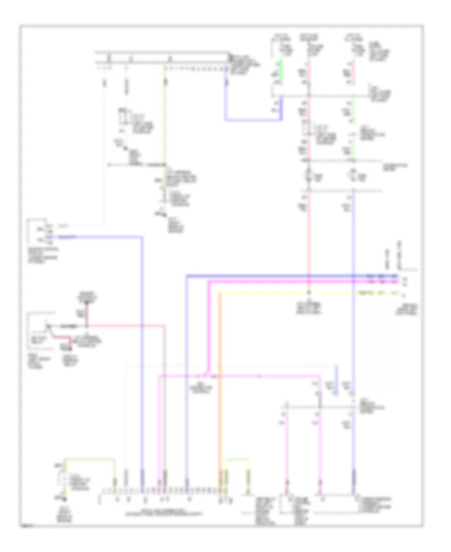
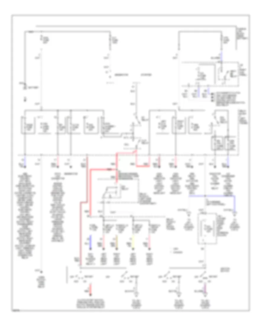
POWER DISTRIBUTION
Power Distribution Wiring Diagram (1 of 2) for Toyota RAV4 1997
List of elements for Power Distribution Wiring Diagram (1 of 2) for Toyota RAV4 1997:
- :canada
- :usa
- A/c condenser fan motor, fan number 2 relay, fan number 3 relay
- A/c fuse 7.5a
- A/c magnetic clutch and lock sensor, a/c amplifier, a/c control switch, defroster mode switch, mg/c relay
- Abs electronic control unit (ecu), back door open detection switch and door lock motor, cigarette lighter, clock, combination meter, open door warning light, cruise control electronic control unit (ecu) driver's door courtesy switch, front passenger's door courtesy switch, left rear door courtesy switch, right rear door courtesy switch, interior light, personal light, radio and player, integration relay
- Abs fuse 60a
- Abs relay, abs actuator, abs electronic control unit (ecu)
- Acc
- Alt fuse 100a
- Alt-s fuse 5a
- Am1 fuse 40a
- Am2 fuse 20a
- Battery
- Cds fan fuse 30a
- Clutch start switch, park/neutral position switch, engine control module, starter relay
- Coil
- Data link connector 1, engine control module, main fuel sender and fuel pump, idle air control valve, egr vacuum solenoid valve (vsv), evap vacuum solenoid valve (vsv), vapor pressure sensor vacuum solenoid valve (vsv), circuit opening relay, efi main relay
- Day- time running light relay 4
- Dim relay
- Dome fuse 15a
- Drl fuse 7.5a
- E/g main relay
- E1 (engine harness, behind right side of radiator)
- Efi fuse 15a
- Fusible link block (near battery)
- Generator
- H-lp relay
- Haz- horn fuse 15a
- Heat- er relay
- High beam indicator light, light control switch, left headlight
- High beam indicator light, light control switch, right headlight
- Horn switch, horn, horn relay
- Htr fuse 50a
- I3 (i/p harness, left kick panel)
- Ignition switch
- J/b (right kick panel)
- J/b 1 (lower finish panel, left side of steering column)
- Left hi hdlmp fuse 10a
- Left high beam head- light
- Left hl-p fuse 15a
- Left lo hdlmp fuse 10a
- Left low beam head- light
- Main fuse 80a
- Main number 1 fuse 30a
- Nca
- Off
- Radiator fan motor, fan number relay
- Rdi fan fuse 30a
- Red
- Relay block (left shock tower)
- Relay block 2 (left shock tower)
- Relay block 6 (left side of engine compartment)
- Right h-lp fuse 15a
- Right hi hdlmp fuse 10a
- Right high beam head- light
- Right lo hdlmp fuse 10a
- Right low beam head- light
- St relay
- Start
- Starter
- To j/b 1 (pin 1k) (diagram 2 of 2)
- To j/b 1 (pin 2k) (diagram 2 of 2)
- To j/b 1 (pin 6d) (diagram 2 of 2)
- To j/b 1 (pin 7d) (diagram 2 of 2)
- To j/b 1 (pin 8d) (diagram 2 of 2)
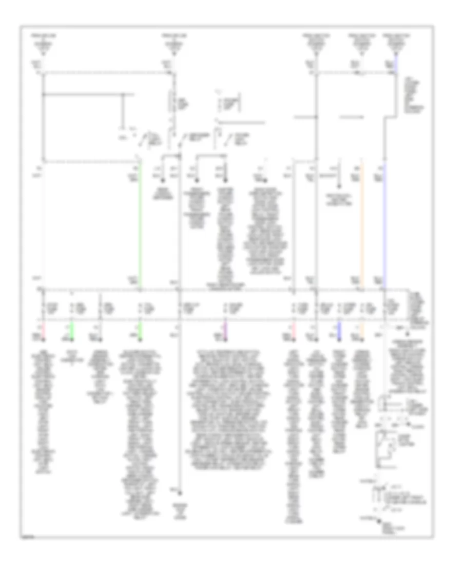
Power Distribution Wiring Diagram (2 of 2) for Toyota RAV4 1997
List of elements for Power Distribution Wiring Diagram (2 of 2) for Toyota RAV4 1997:
- A/c triple pressure switch, a/c water temper- ature switch, abs elec- tronic control unit (ecu), cruise control elec- tronic control unit (ecu), e/g main relay, fan number 1 relay, fan number 2 relay
- A/t fluid temperature switch, abs electronic control unit (ecu), back-up light switch (m/t), brake fluid level warning switch, blower resistor, blower switch, center differential lock warning buzzer switch, center differential lock control switch, abs warning light, seat belt warning light, combination meter, cruise control clutch switch, cruise control electronic control unit (ecu), data link connector 1, electronically controlled transmission pattern select switch, engine control module, main fuel sender and fuel pump, sub fuel sender, generator, oil pressure switch, o/d main switch, park/neutral position switch (a/t), parking brake switch, rear window defogger switch, left back-up light, right back-up light, vehicle speed sensor, center differential lock number 1 vacuum solenoid valve (vsv), center differential lock number 2 vacuum solenoid valve (vsv), water temperature sensor, defogger relay, integration relay, power main relay, heater relay
- Abs electronic control unit (ecu), cruise control electronic control unit (ecu), engine control module, high mounted stop light, left stop light, right stop light, shift lock electronic control unit (ecu), stop light switch
- Airbag sensor assembly, charge warning light, comb- ination meter, engine control module, generator, circuit opening relay, efi main relay
- Airbag sensor assembly, combination meter, srs warning light, data link connector 1, efi main relay
- Airbag sensor assembly, radio and player, remote control mirror switch, left remote control mirror, right remote control mirror, shift lock elec- tronic control unit (ecu), integration relay
- B10
- Back door open detection switch and door lock motor, door lock control relay, front passenger's door lock control switch, left rear door lock motor, right rear door lock motor, driver's door lock motor; door key lock and unlock switch, front passenger's door lock motor; door key lock and unlock switch
- Blower switch, center differential lock control switch, cigarette lighter illumination, clock, combination meter, electronically controlled transmission pattern select switch, left front side marker light, right front side marker light, left front turn signal light and parking light, right front turn signal light and parking light, hazard switch, license plate light, o/d main switch, radio and player, rear window defogger switch, rheostat, left taillight, right taillight, left rear side marker light, right rear side marker light, integration relay
- Cig & rad fuse 15a
- Cigar- ette lighter
- Clock
- Coil
- Data link connector
- Def fuse 30a
- Def-i/up fuse 7.5a
- Defogger relay
- E11
- Ecu-ig fuse 7.5a
- Engine idle up diode
- From ignition switch (diagram 1 of 2)
- From splice i3 (diagram 1 of 2)
- Front passenger's power window switch, front passenger's power window motor
- Front wiper and washer switch, rear wiper and washer switch, front washer motor, front wiper motor, rear washer motor, rear wiper motor, rear wiper relay
- Fuse block (lower finish panel, left side of steering column)
- G203 (right kick panel)
- Gauge fuse 10a
- H14
- Ign fuse 7.5a
- Ignition coil, igniter, noise filter
- J/b 1 (lower finish panel, left side of steering column)
- J/b 1 (under left side of dash)
- J/c 10
- J/c 11
- J/c 11/ j/c 10 (under left front of center console)
- L10
- Left turn signal indicator light, right turn signal indicator light, turn signal switch, left front turn signal light and parking light, right front turn signal light and parking light, left rear turn signal light, right rear turn signal light, turn signal flasher
- Master power window switch, left rear power window switch, right rear power window switch, driver's power window motor, left rear power window motor, right rear power window motor
- Obd fuse 7.5a
- Power fuse 30a
- Power main relay
- Rear window defogger
- Srs fuse 7.5a
- Stop fuse 10a
- Tail fuse 10a
- Tail- light relay
- Turn fuse 7.5a
- Wiper fuse 20a
POWER DOOR LOCKS
Power Door Lock Wiring Diagram for Toyota RAV4 1997
List of elements for Power Door Lock Wiring Diagram for Toyota RAV4 1997:
- (body harn, inside left front door) b4
- (body harn, right kick panel) b7
- (i/p harn, below right side of dash) i9
- 2 door
- 4 door
- B10 (body harn, inside center of back door)
- B11 (body harn, left rear door sill)
- B19
- B21
- Back door lock motor
- D11
- D13
- Door lock control relay (right side of dash)
- Door lock control switch (power window master switch)
- Driver's side door key lock/ unlock switch
- Driver's side door lock motor
- Front passenger's door key lock/ unlock switch
- Front passenger's door lock control switch
- Front passenger's door lock motor
- G200 (left kick panel)
- G203 (right kick panel)
- G206 (center of dash)
- Hot at all times
- J/b 1 (left side of steering column)
- J/b 4 (right kick panel)
- Junction block 3 (center of dash)
- Junction block 6 (behind radio)
- Left rear door lock motor
- Lock
- Power fuse 30a
- Red
- Right rear door lock motor
- Solid state
- Unlock
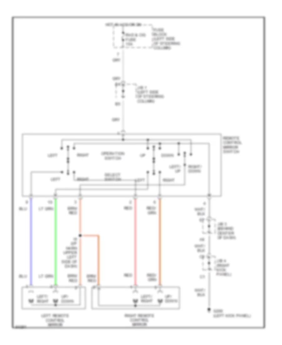
POWER MIRRORS
Power Mirror Wiring Diagram for Toyota RAV4 1997
List of elements for Power Mirror Wiring Diagram for Toyota RAV4 1997:
- Down
- Fuse block (left side of steering column)
- G200 (left kick panel)
- Hot in acc or on
- I6 (i/p harn upper left side of dash)
- J/b 1 (left side of steering column)
- J/b 3 (behind center of dash)
- J/b 4 (right kick panel)
- Left
- Left remote control mirror
- Left/ right
- Left/ up
- Operation switch
- Rad & cig fuse 15a
- Red
- Remote control mirror switch
- Right
- Right remote control mirror
- Right/ down
- Select switch
- Up/ down
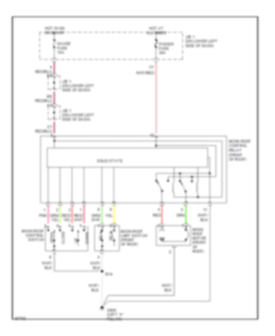
POWER TOP/SUNROOF
Moonroof Wiring Diagram for Toyota RAV4 1997
List of elements for Moonroof Wiring Diagram for Toyota RAV4 1997:
- (front of roof)
- B14
- Close
- Down
- G900 (left "a" pillar)
- Gauge fuse 10a
- Hot at all times
- Hot in on or start
- J/b 1 (on lower left side of dash)
- Moon roof control relay
- Moon roof control switch
- Moon roof limit switch (front of roof)
- Moon roof motor (front of roof)
- No.1
- No.2
- Open
- Pnk
- Power fuse 30a
- Red
- Solid state
POWER WINDOWS
Power Window Wiring Diagram for Toyota RAV4 1997
List of elements for Power Window Wiring Diagram for Toyota RAV4 1997:
- (2 door)
- (4 door)
- (4-door) (2-door)
- (in left front door) b2
- 2-door
- 4-door
- A10
- A11
- A12
- A13
- A14
- B10
- B11 (left rear door sill)
- B2 (in left front door)
- Door lock control relay (right side of i/p)
- Down
- Driver's
- Driver's power window motor
- Front passenger's door courtesy switch
- Fuse block (left side of dash)
- G200 (left kick panel)
- G203 (right kick panel)
- G302 (below center console)
- Gauge fuse 10a
- H15
- Hot at all times
- Hot in on or start
- J/b 1 (left side of dash)
- J/b 3 (behind center of dash)
- J/b 4 (right kick panel)
- J/c 6 (behind center of dash)
- Key off power window
- L18
- Left rear
- Left rear power window motor
- Left rear power window switch
- Lock
- Normal
- Power fuse 30a
- Power main relay
- Power window master switch
- Red
- Right front
- Right front power window motor
- Right front power window switch
- Right rear
- Right rear power window motor
- Right rear power window switch
- Solid state
- Window lock switch
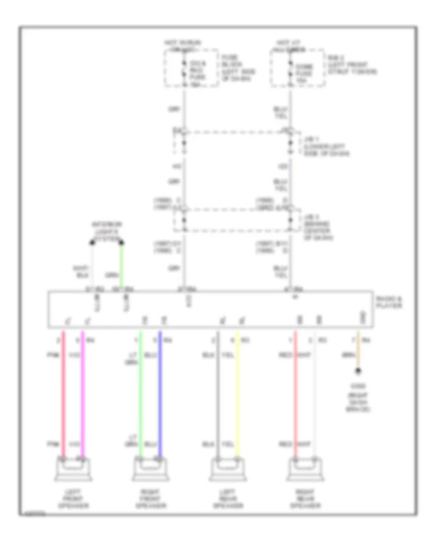
RADIO
Radio Wiring Diagrams for Toyota RAV4 1997
List of elements for Radio Wiring Diagrams for Toyota RAV4 1997:
- (1996) (1997)
- (1997) (1996)
- (right dash brace)
- Acc
- B11 d
- C a1
- Cig & rad fuse 15a
- D a10
- D1 c
- Dome fuse 15a
- Fuse block (left side of dash)
- G302
- Gnd
- Hot at all times
- Hot in run or acc
- I22
- Illum
- Interior lights system
- J/b 1 (lower left side of dash)
- J/b 3 (behind center of dash)
- Left front speaker
- Left rear speaker
- Pnk
- R/b 2 (left front strut tower)
- Radio & player
- Red
- Right front speaker
- Right rear speaker
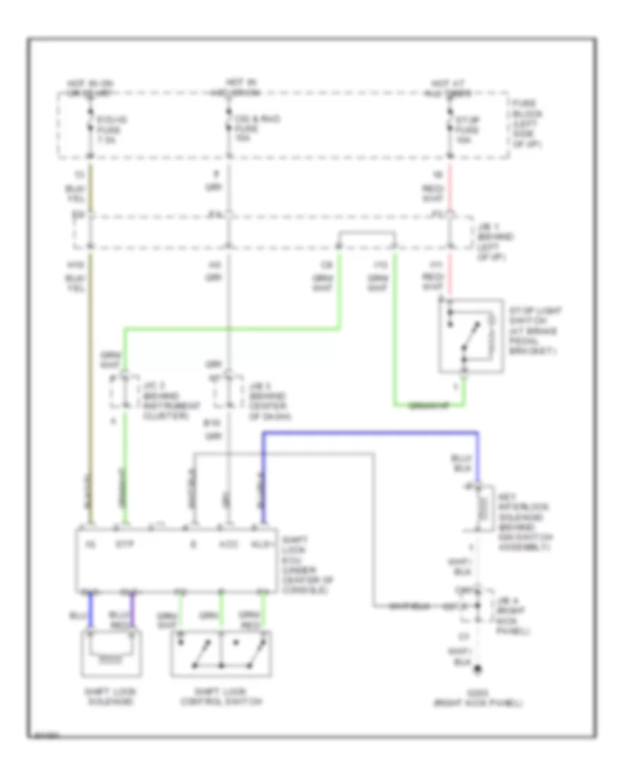
SHIFT INTERLOCKS
Shift Interlock Wiring Diagram for Toyota RAV4 1997
List of elements for Shift Interlock Wiring Diagram for Toyota RAV4 1997:
- Acc
- B10
- C10
- Cig & rad fuse 15a
- Ecu-ig fuse 7.5a
- Fuse block (left side of i/p)
- G203 (right kick panel)
- H10
- Hot at all times
- Hot in acc or on
- Hot in on or start
- I11
- I13
- J/b 1 (behind left of i/p)
- J/b 3 (behind center of dash)
- J/b 4 (right kick panel)
- J/c 3 (behind instrument cluster)
- Key interlock solenoid (behind ign switch assembly)
- Kls+
- Shift lock control switch
- Shift lock ecu (under center of console)
- Shift lock solenoid
- Sls+
- Sls-
- Stop fuse 10a
- Stop light switch (at brake pedal bracket)
- Stp
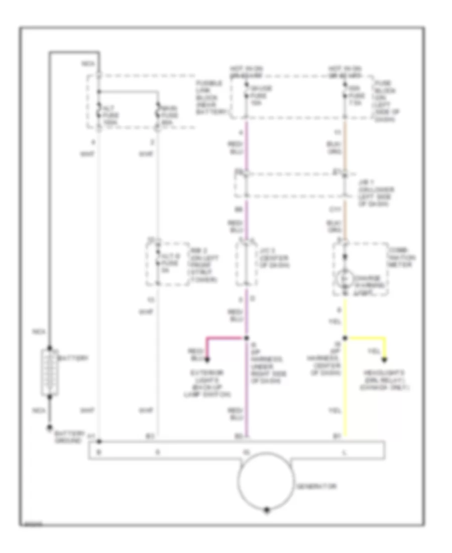
STARTING/CHARGING
Charging Wiring Diagram for Toyota RAV4 1997
List of elements for Charging Wiring Diagram for Toyota RAV4 1997:
- Alt fuse 100a
- Alt-s fuse 5a
- Battery
- Battery ground
- C11
- Charge warning light
- Comb- ination meter
- Exterior lights (back-up lamp switch)
- Fuse block (on left side of dash)
- Fusible link block (near battery)
- Gauge fuse 10a
- Generator
- Headlights (drl relay) (canada only)
- Hot in on or start
- I5 (i/p harness, under right side of dash)
- I8 (i/p harness, center of dash)
- Ign fuse 7.5a
- J/b 1 (on lower left side of dash)
- J/c 3 (center of dash)
- Main fuse 80a
- Nca
- R/b 2 (on left front strut tower)
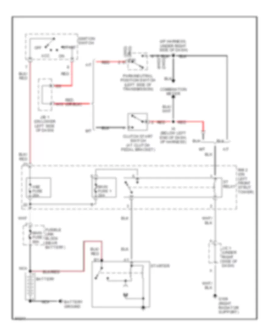
Starting Wiring Diagram for Toyota RAV4 1997
List of elements for Starting Wiring Diagram for Toyota RAV4 1997:
- (2wd)
- (4wd)
- (i/p harness, under right side of dash) i5
- A/t
- Acc
- Am2 fuse 20a
- Battery
- Battery ground
- Clutch start switch (at clutch pedal bracket)
- Combination meter
- Fusible link block (near battery)
- G109 (right radiator support)
- H13
- I6 (below left end of dash, i/p harness)
- Ignition switch
- J/b 1 (on lower left side of dash)
- J/c 1 (under right side of dash)
- M/t
- Main fuse 1 30a
- Main fuse 80a
- Nca
- Off
- P/n (4wd)
- Park/neutral position switch (left side of transmission)
- R/b 2 (on left front strut tower)
- Red
- St relay
- Start
- Starter
SUPPLEMENTAL RESTRAINTS
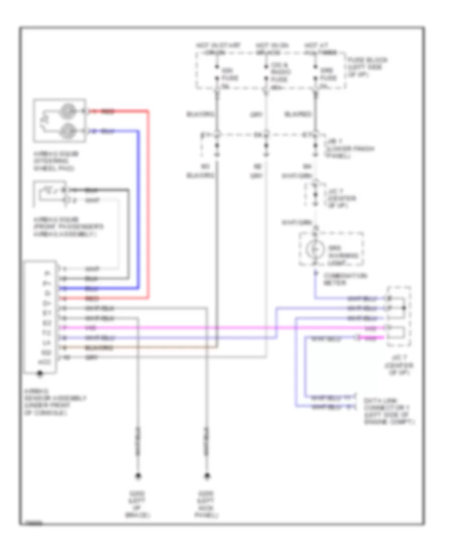
Supplemental Restraint Wiring Diagram for Toyota RAV4 1997
List of elements for Supplemental Restraint Wiring Diagram for Toyota RAV4 1997:
- (center of i/p)
- Acc
- Airbag sensor assembly (under front of console)
- Airbag squib (front passenger's airbag assembly)
- Airbag squib (steering wheel pad)
- Cig & radio fuse 15a
- Combination meter
- Data link connector 1 (left side of engine compt)
- Fuse block (left side of i/p)
- G200 (left kick panel)
- G202 (left i/p brace)
- Hot at all times
- Hot in on or acc
- Hot in start
- Ig2
- Ign fuse 5a
- J/b 1 (lower finish panel)
- J/c 7
- J/c 7 (center of i/p)
- Or on
- Red
- Srs fuse 5a
- Srs warning light
TRANSMISSION
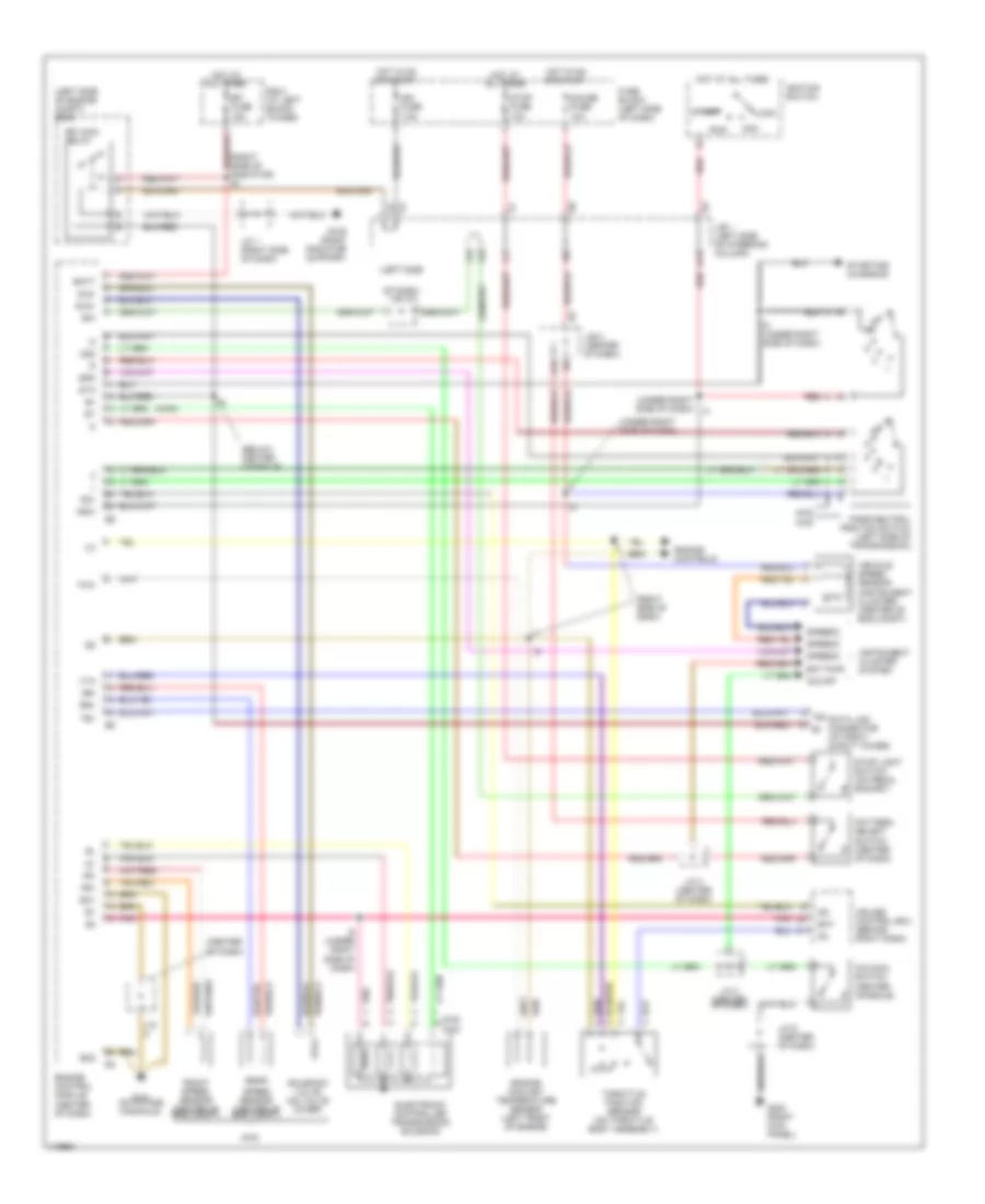
A/T Wiring Diagram for Toyota RAV4 1997
List of elements for A/T Wiring Diagram for Toyota RAV4 1997:
- (4wd)
- (below center console)
- (center of dash)
- (left side
- (left side of engine compt) r/b 6
- (right side of dash)
- (right side of radiator) e1
- (under right side of dash)
- 2wd
- 4wd
- A15
- Acc
- B/k
- Batt
- Cruise control ecu (behind right dash)
- Data link connector (at right strut tower)
- Ect
- Ect pwr
- Efi fuse 15a
- Efi main relay
- Electronic controlled transmission solenoid
- Engine control module (center of dash)
- Engine controls
- Engine coolant temperature sensor (left front of engine)
- Eo1
- Eo2
- Fr+
- Fr-
- Front speed sensor (center of eng compt)
- Fuse block (left side of dash)
- G109 (right radiator support)
- G131 (on intake manifold)
- G203 (right kick panel)
- Gauge fuse 10a
- H13
- Hot at all times
- Hot in on or start
- I11
- I13
- I5 (under right side of dash)
- Idl
- Ign fuse 7.5a
- Ignition switch
- Instrument cluster system
- J/b 1 (left side of steering column)
- J/b 3 (center of dash)
- J/c
- J/c 1 (right side of dash)
- J/c 3 (center of dash)
- J/c 6 (center of dash)
- Lock
- Nsw
- O/d main switch (center console)
- O/d off
- Od1
- Od2
- Of dash) j/c 3
- Park/neutral position switch (left side of transmission)
- Pattern select switch (center of dash)
- Pnk
- R/b 2 (at left shock tower)
- Rear
- Red
- Rr+
- Rr-
- Run
- Sld+
- Sld-
- Solenoid valve (on valve cover)
- Spd
- Speed sensor (center of eng compt)
- Speedo
- Sta
- Start
- Starting/ charging
- Stop fuse 10a
- Stop light switch (on pedal backet)
- Te1
- Te1 b+
- Throttle position sensor (on throttle body assembly)
- Thw
- Vehicle speed sensor (instrument cluster) (center of eng compt)
- Vta
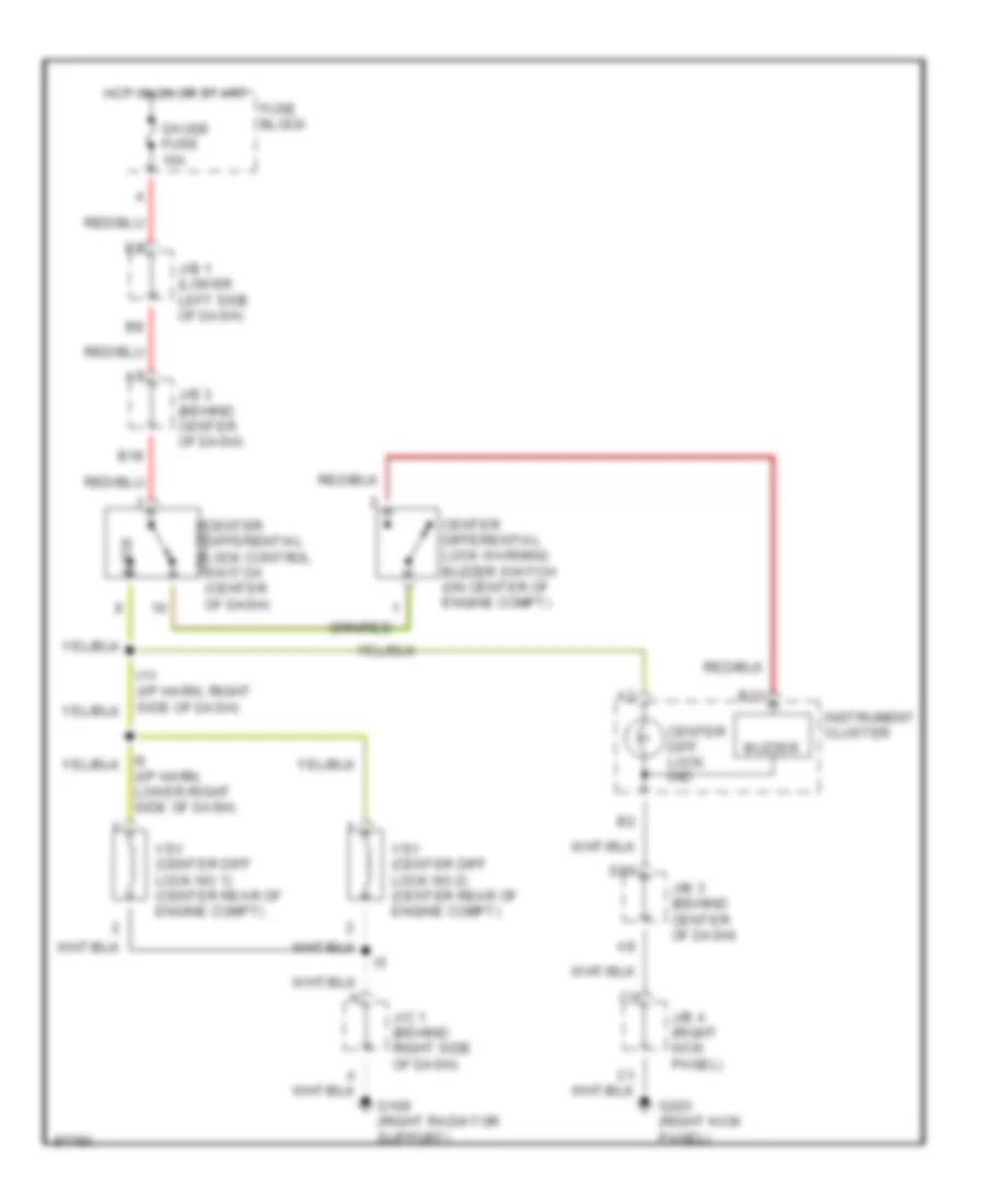
Center Differential Lock Wiring Diagram, M/T for Toyota RAV4 1997
List of elements for Center Differential Lock Wiring Diagram, M/T for Toyota RAV4 1997:
- (i/p harn, lower right side of dash)
- B13
- B18
- Buzzer
- Center diff. lock ind
- Center differential lock control switch unlock (center of dash)
- Center differential lock warning buzzer switch (on center of engine compt)
- D20
- Fuse block
- G109 (right radiator support)
- G203 (right kick panel)
- Gauge fuse 10a
- Hot in on or start
- I11 (i/p harn, right side of dash)
- Instrument cluster
- J/b 1 (lower left side of dash)
- J/b 3 (behind center of dash)
- J/b 4 (right kick panel)
- J/c 1 (behind right side of dash)
- Lock
- Vsv (center diff lock no 1) (center rear of engine compt)
- Vsv (center diff lock no 2) (center rear of engine compt)
WARNING SYSTEMS
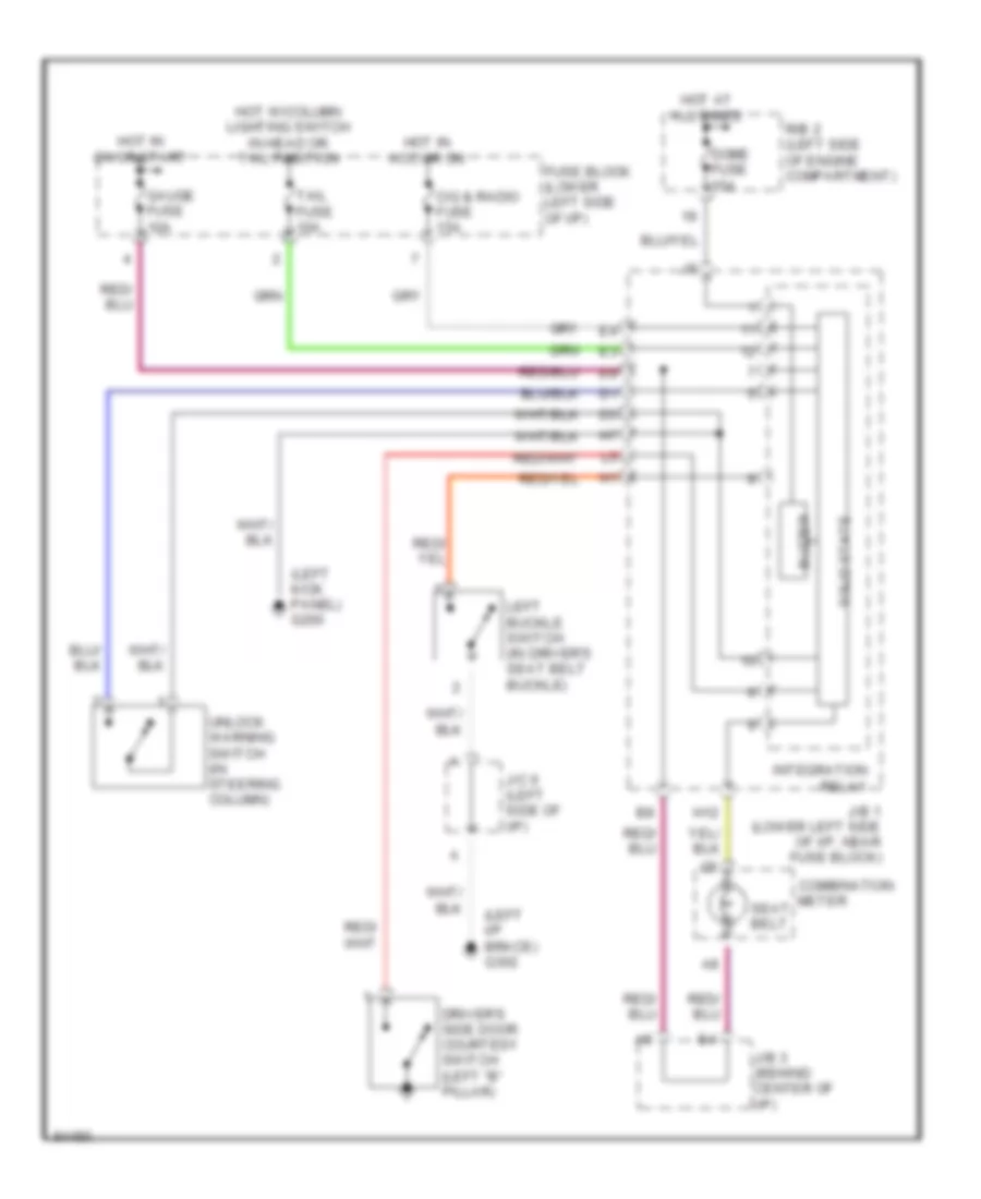
Warning System Wiring Diagrams for Toyota RAV4 1997
List of elements for Warning System Wiring Diagrams for Toyota RAV4 1997:
- (left i/p brace) g302
- (left kick panel) g200
- Buzzer
- Cig & radio fuse 15a
- Combination
- Dome fuse 15a
- Driver's side door courtesy switch (left "b" pillar)
- Fuse block (lower left side of i/p)
- Gauge fuse 10a
- H12
- Hot at all times
- Hot in acc or on
- Hot in on or start
- Hot w/column lighting switch in head or tail position
- Integration relay
- J/b 1 (lower left side of i/p, near fuse block)
- J/b 3 (behind center of i/p)
- J/c 6 (left side of i/p)
- Left buckle switch (in driver's seat belt buckle)
- Meter
- R/b 2 (left side of engine compartment)
- Seat belt
- Solid state
- Tail fuse 10a
- Unlock warning switch (in steering column)
WIPER/WASHER
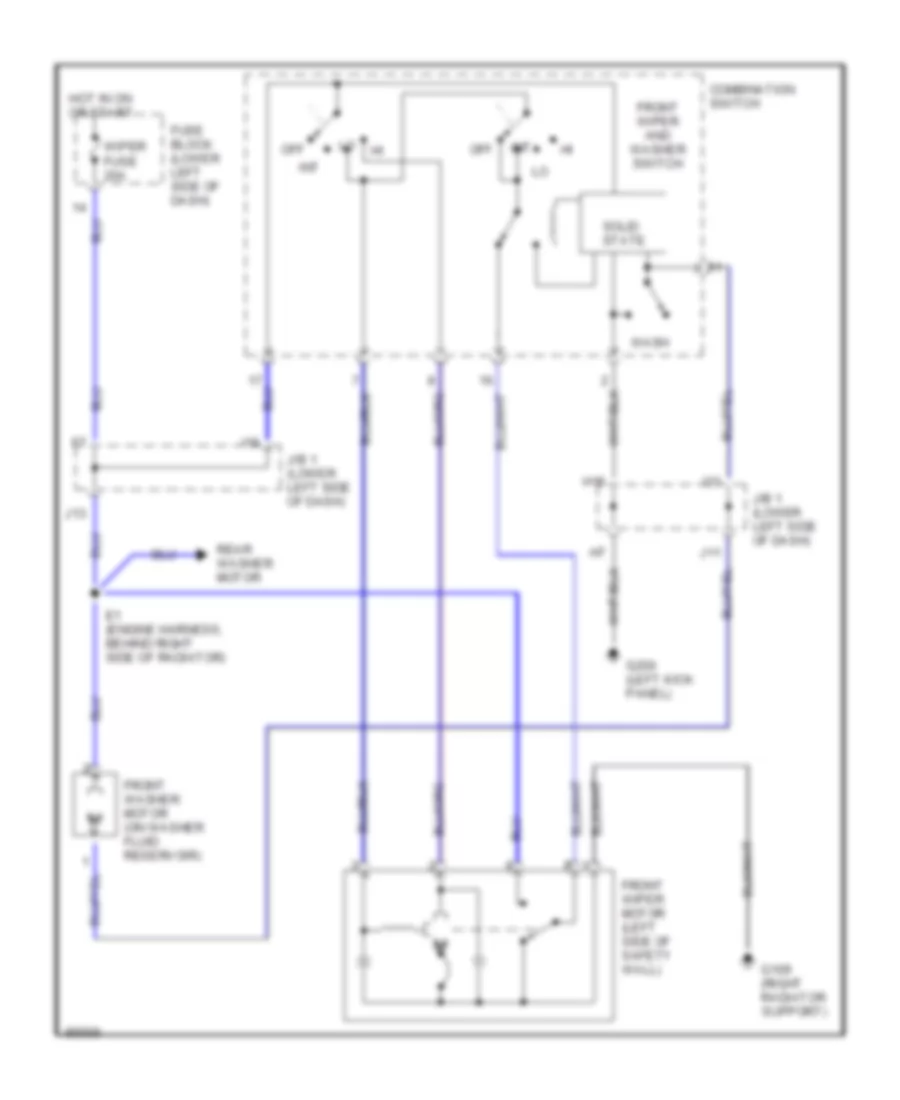
Front Wiper/Washer Wiring Diagram for Toyota RAV4 1997
List of elements for Front Wiper/Washer Wiring Diagram for Toyota RAV4 1997:
- Combination switch
- E1 (engine harness, behind right side of radiator)
- Front washer motor (on washer fluid reservoir)
- Front wiper and washer switch
- Front wiper motor (left side of safety wall)
- Fuse block (lower left side of dash)
- G109 (right radiator support)
- G200 (left kick panel)
- H16
- Hot in on or start
- I18
- I21
- Int
- J/b 1 (lower left side of dash)
- J11
- J13
- Off
- Rear washer motor
- Solid state
- Wash
- Wiper fuse 20a
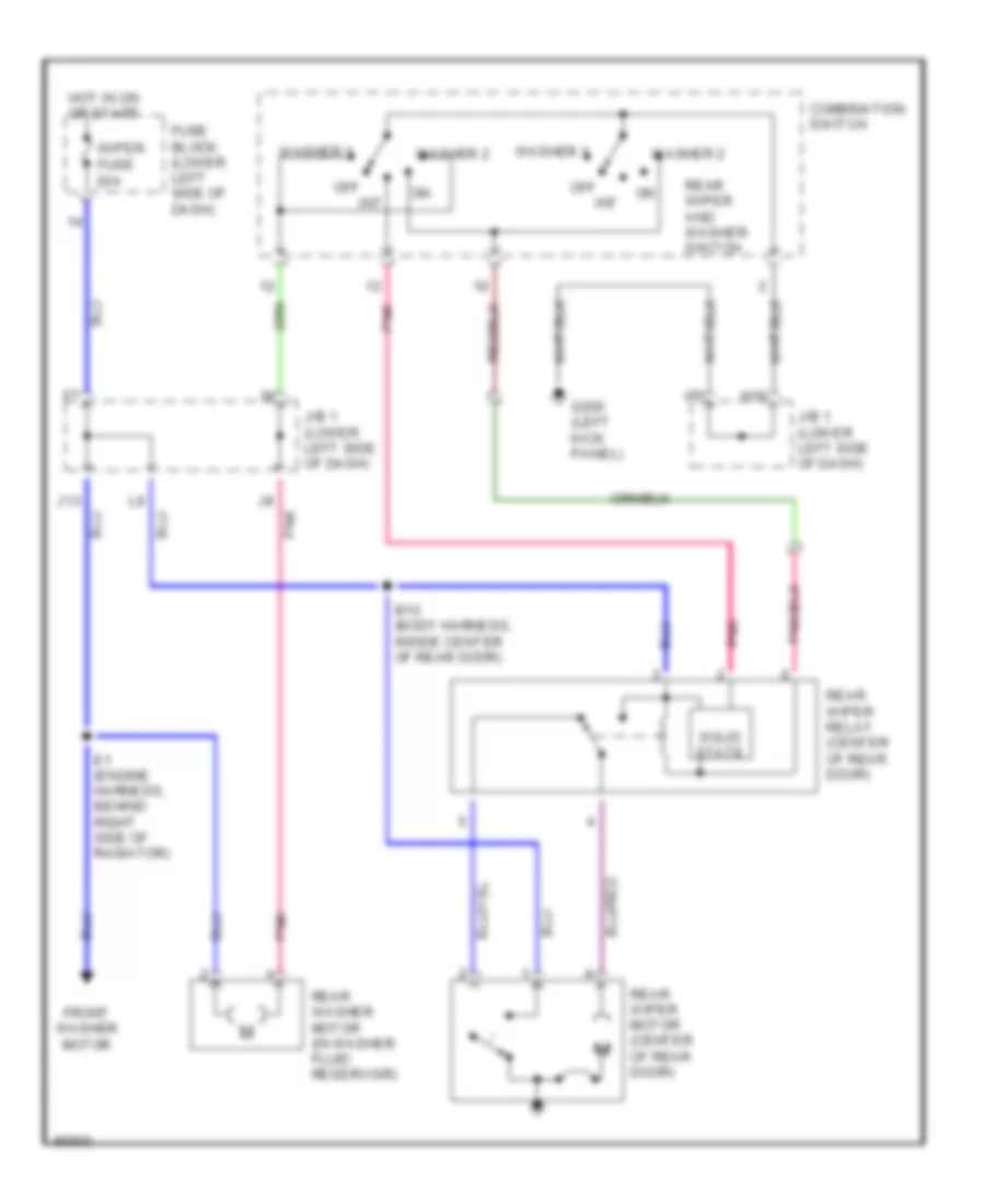
Rear Wiper/Washer Wiring Diagram for Toyota RAV4 1997
List of elements for Rear Wiper/Washer Wiring Diagram for Toyota RAV4 1997:
- B10 (body harness, inside center of rear door)
- Combination switch
- E1 (engine harness, behind right side of radiator)
- Front washer motor
- Fuse block (lower left side of dash)
- G200 (left kick panel)
- H16
- Hot in on or start
- Int
- J/b 1 (lower left side of dash)
- J13
- Off
- Pnk
- Rear washer motor (in washer fluid reservoir)
- Rear wiper and washer switch
- Rear wiper motor (center of rear door)
- Rear wiper relay (center of rear door)
- Solid state
- Washer 1
- Washer 2
- Wiper fuse 20a

 Čeština
 Dansk
Dansk Deutsch
 Ελληνικά
 English
 Español
 Suomi
Suomi Français
 Français
 עברית
עברית Hrvatski
 Magyar
 Italiano
 日本語
日本語 한국어
한국어 Nederlands
 Polski
 Português
 Português
 Română
 Русский
 Slovenčina
 Slovenščina
 Svenska
 Türkçe
 中文 (中国)