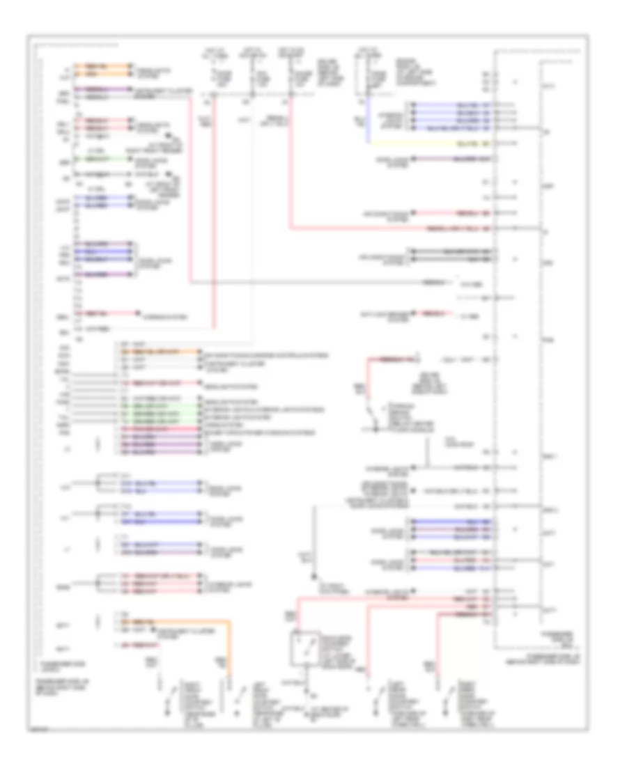
AIR CONDITIONING
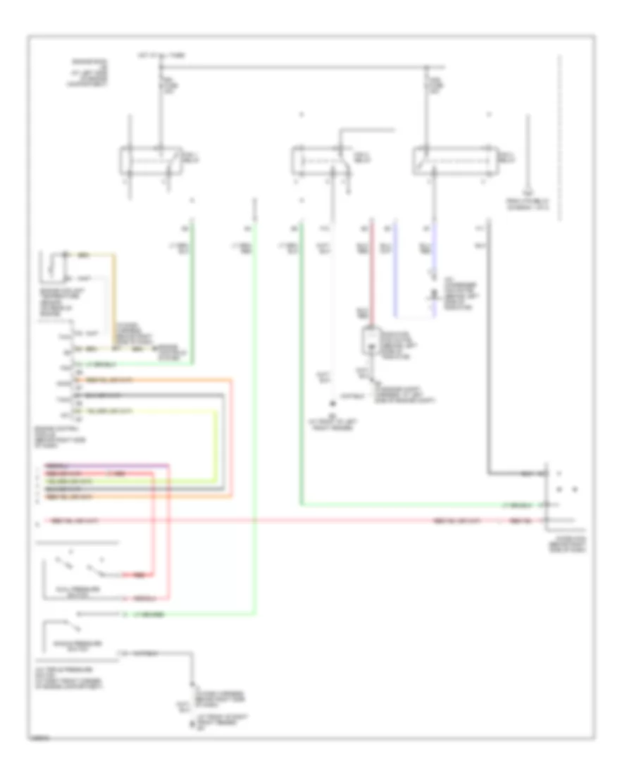
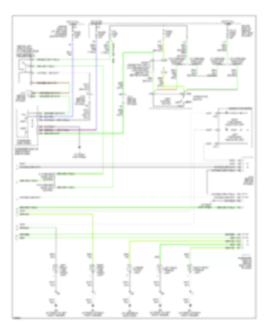
Manual A/C Wiring Diagram (1 of 2) for Toyota RAV4 2005
 https://portal-diagnostov.com/license.html
Automotive Electricians Portal FZCO
Automotive Electricians Portal FZCO
https://portal-diagnostov.com/license.html
https://portal-diagnostov.com/license.html
Automotive Electricians Portal FZCO
Automotive Electricians Portal FZCO
List of elements for Manual A/C Wiring Diagram (1 of 2) for Toyota RAV4 2005:
- (at front of left front fender) ed
- (at right kick panel) ii
- (in dash harness, behind right side of dash) i1
- A/c
- A/c amplifier (behind center of dash)
- A/c control switch
- A/c fuse 5a
- A/c magnetic clutch & lock sensor (at left front of engine compt)
- A/c thermistor (behind center of dash)
- Ac1
- Acc
- Acc fuse 7.5a
- Acin
- Air inlet control servo motor (behind right side of dash)
- Blower motor (behind right side of dash)
- Blower resistor (behind lower right side of dash)
- Blower switch
- Driver side j/b (behind left side of dash)
- Ecu ig fuse 10a
- Engine room j/b (at left side of engine compartment)
- F10
- Frs
- G10
- Gauge fuse 10a
- Gnd1
- Gnd2
- Ground
- Hot at all times
- Hot in acc or on
- Hot in on or start
- Htr fuse 40a
- Htr relay
- If (below center of dash, at left dash brace)
- Ig (below center of dash, at right dash brace)
- Ig+
- Ign
- Ill+
- Ill-
- Interior lights system
- J28
- Junction connector 4 (behind center of dash)
- Junction connector 5 (behind center of dash)
- Led
- Lock
- Mgc
- Mgp
- Off
- Passenger side j/b (behind right side of dash)
- Passenger side j/b ecu
- Pnk
- Prs
- Rec
- Red
- To fan 3 relay (diagram 2 of 2)
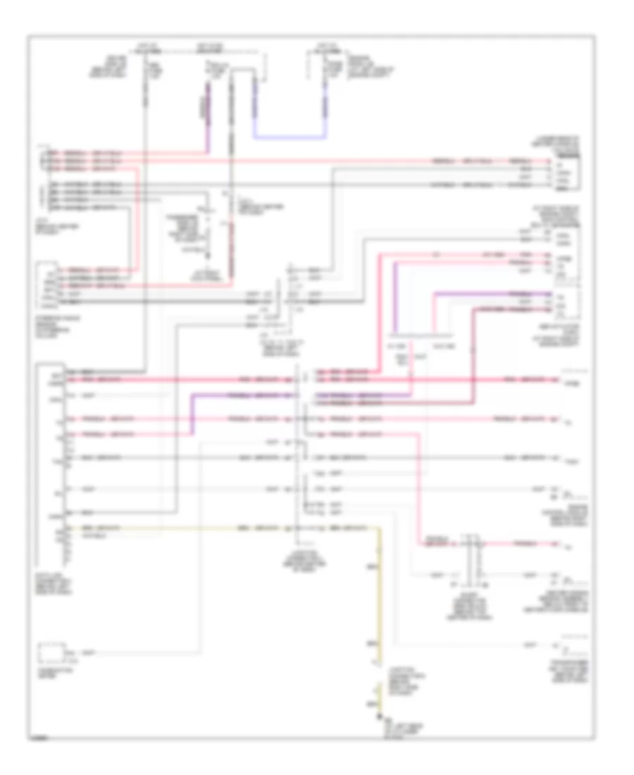
Manual A/C Wiring Diagram (2 of 2) for Toyota RAV4 2005
List of elements for Manual A/C Wiring Diagram (2 of 2) for Toyota RAV4 2005:
- (at front of right front fender) ea
- (in dash harness, behind right side of dash) i2
- A/c condenser fan motor (behind left side of radiator)
- A/c triple pressure switch (at right front corner of engine compartment)
- Ac1
- Acmg
- Cds fuse 30a
- Diode (fan) (behind right side of dash)
- Dual pressure switch
- E5 (in engine compt harness, at left side of engine compt)
- Ed (at front of left front fender)
- Engine control module (behind right side of dash)
- Engine controls system
- Engine coolant temperature sensor (on rear of engine)
- Engine room j/b (at left side of engine compartment)
- F10
- F11
- Fan
- Fan 1 relay
- Fan 2 relay
- Fan 3 relay
- From htr relay (diagram 1 of 2)
- Hot at all times
- I3 (in dash harness, behind right side of dash)
- Radiator fan motor (behind left side of radiator)
- Rdi fuse 30a
- Red
- Single pressure switch
- Tach
- Thw
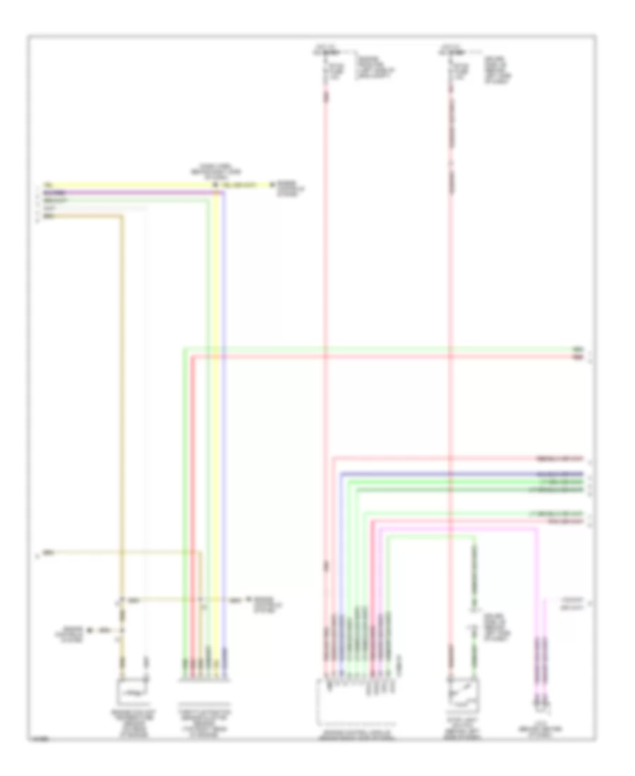
ANTI-LOCK BRAKES
Anti-lock Brakes Wiring Diagram, with VSC (1 of 2) for Toyota RAV4 2005
List of elements for Anti-lock Brakes Wiring Diagram, with VSC (1 of 2) for Toyota RAV4 2005:
- (2wd)
- (at front of right front fender) ea
- +bs
- Abs 1 fuse 50a
- Abs 2 fuse 30a
- Abs ind
- Ambient temperature sensor (behind left side of front grille)
- Brake ind
- Brl
- Bsah
- Bsar
- Bsbh
- Bsbr
- Bsch
- Bscr
- Bsdh
- Bsdr
- C12
- C15
- Canh
- Canl
- Combination meter
- Csw
- D/g
- Dome fuse 10a
- Driver side j/b (behind left side of dash)
- E12
- E16
- E21
- Ecu ig fuse 10a
- Eng+
- Eng-
- Engine room j/b (at left side of engine compt)
- Fl+
- Fl-
- Fr+
- Fr-
- Gauge fuse 10a
- Gnd1
- Gnd2
- Hot at all times
- Hot in on or start
- Ig1
- Ig2 fuse 10a
- Ind
- Init
- J20
- J28
- Left front abs speed sensor (mounted on hub assembly of left front wheel)
- Left rear abs speed sensor (mounted on hub assembly of left rear wheel)
- Mrf
- Neo
- Oil pressure sensor
- Pkb
- Pmc
- Pnk
- Red
- Right front abs speed sensor (mounted on hub assembly of right front wheel)
- Right rear abs speed sensor (mounted on hub assembly of right rear wheel)
- Rl+
- Rl-
- Rr+
- Rr-
- Sah
- Sar
- Sbh
- Sbr
- Sch
- Scr
- Sdh
- Sdr
- Skid control ecu w/ actuator (at right side of engine compt)
- Slip ind
- Sml+
- Sml-
- Smp+
- Smp-
- Stop fuse 10a
- Stoplight switch (behind left side of dash)
- Stp
- Tgnd
- Tire pressure ind
- Trac off ind
- Trc+
- Trc-
- Tsi
- Vcm
- Vsc trac ind
- Vscw
- Wfse
- Wtir
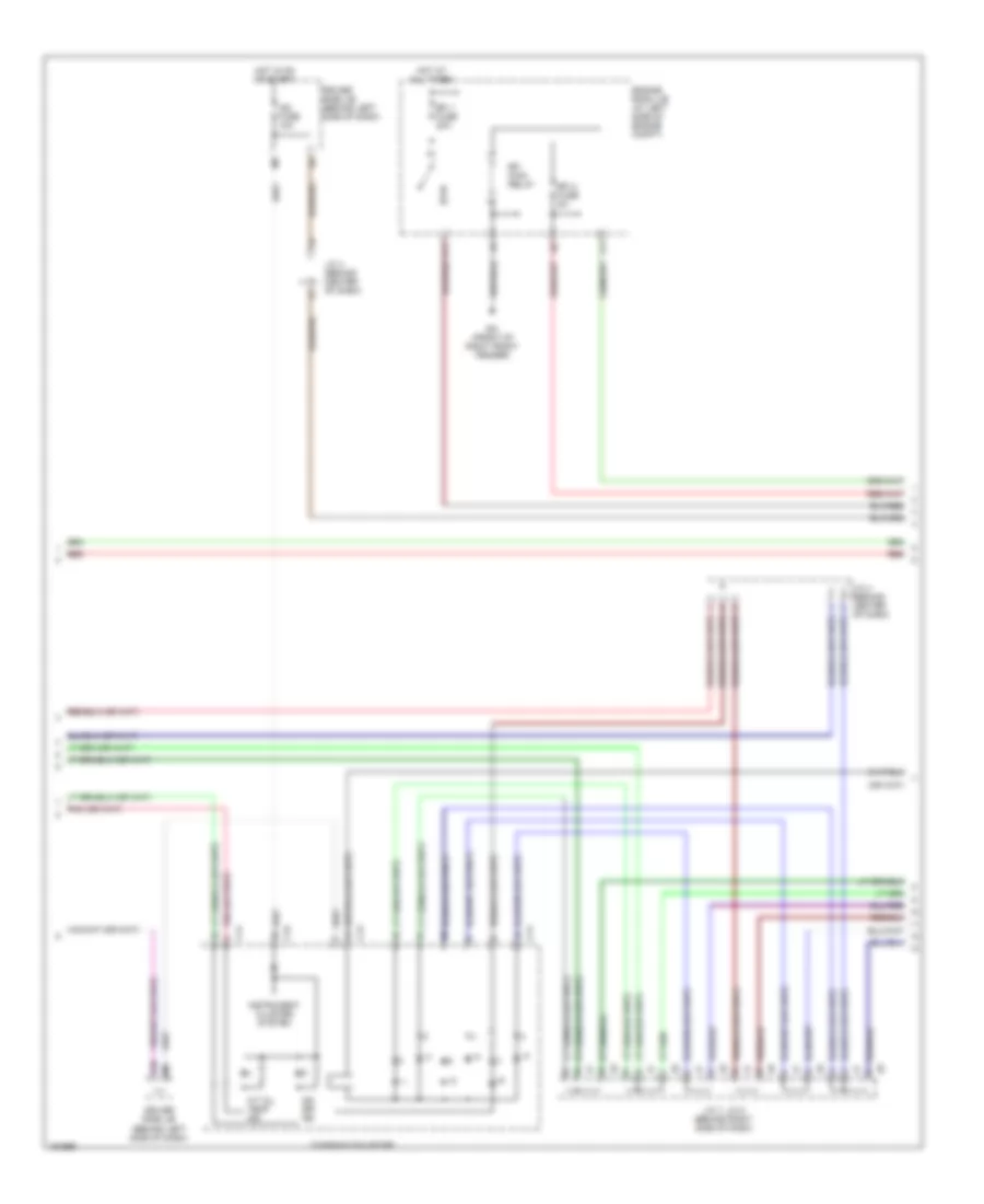
Anti-lock Brakes Wiring Diagram, with VSC (2 of 2) for Toyota RAV4 2005
List of elements for Anti-lock Brakes Wiring Diagram, with VSC (2 of 2) for Toyota RAV4 2005:
- (at left rear corner of engine compt) brake fluid level warning switch
- (below center floor console) parking brake switch
- Abs cut relay
- Abs mtr relay
- Abs r/b (at left side of engine compt)
- Bat
- Brk
- Canh
- Canl
- Data link connector 3 (behind left side of dash)
- Driver side j/b (behind left side of dash)
- Ea (at front of right front fender)
- Eng+
- Eng-
- Engine control module (behind right side of dash)
- Engine room j/b (at left side of engine compt)
- Ess
- G10
- Gnd
- Gnd1
- Gnd2
- Ig1
- Ii (at right kick panel)
- J/c 10, 11, 12 & 13 (behind left side of dash)
- J/c 4 (behind center of dash)
- J/c 5 (behind center of dash)
- J/c 7 & 8 (behind right side of dash)
- J11
- J12
- J13
- M11
- Neo
- P/n
- Park/neutral position switch (at left side of engine compt)
- Passenger side j/b (behind right side of dash)
- Passenger side j/b ecu
- Pkb
- Pnk
- Red
- Sil
- Steering angle sensor (in steering column)
- Tire pressure warning standardization switch
- Trac off switch
- Trc+
- Trc-
- Vsc warning buzzer (behind left end of dash)
- Wsfe
- Yaw rate sensor (under rear of center console)
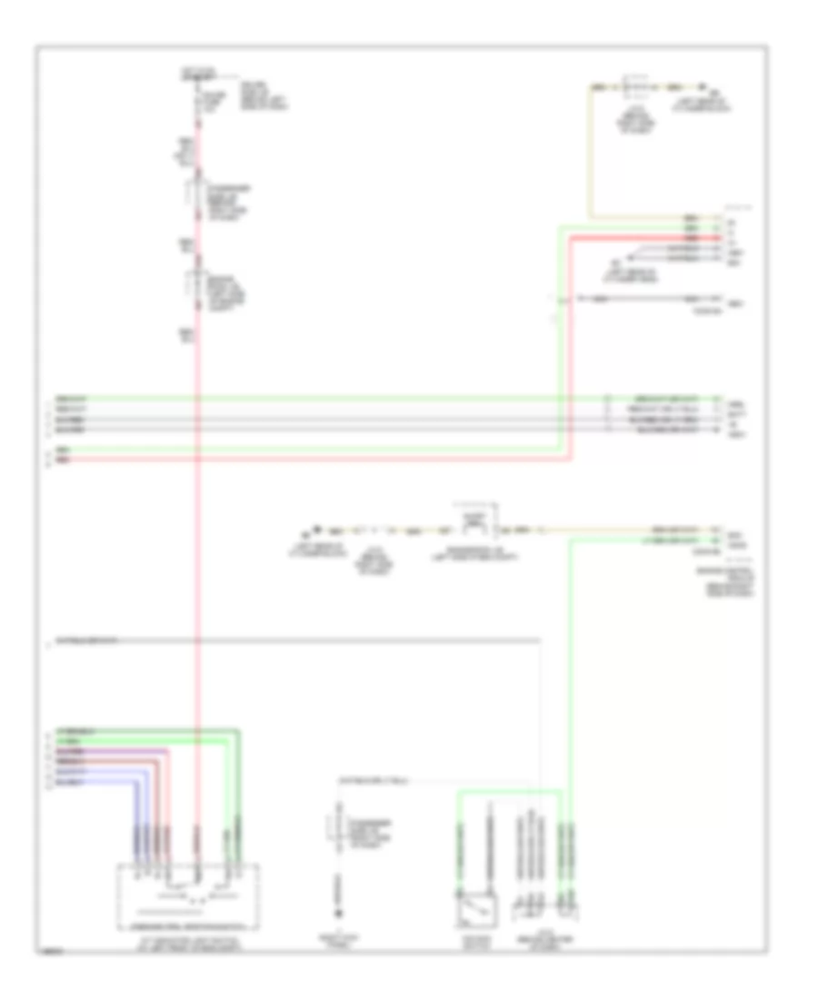
Anti-lock Brakes Wiring Diagram, without VSC for Toyota RAV4 2005
List of elements for Anti-lock Brakes Wiring Diagram, without VSC for Toyota RAV4 2005:
- (at front of right front fender) ea
- (in dash harness, behind right nca side of dash) i3
- +bm
- +bs
- Abs 1 fuse 50a
- Abs 2 fuse 30a
- Abs actuator & ecu (at right side of engine compt)
- Abs deceleration sensor (4wd) (below rear of center floor console)
- Abs ind
- Ambient temperature sensor (behind left side of front grille)
- Brake fluid level warning switch (at left rear corner of engine compt)
- Brake ind
- Brk
- Brl
- Bsah
- Bsar
- Bsbh
- Bsbr
- Bsch
- Bscr
- Bsdh
- Bsdr
- C12
- C15
- Combination meter
- D/g
- Data link connector 3 (behind left side of dash)
- Driver side j/b (behind left side of dash)
- E12
- E21
- Ea (at front of right front fender)
- Ecu ig fuse 10a
- Engine room j/b (at left side of engine compt)
- Fl+
- Fl-
- Fr+
- Fr-
- Gauge fuse 10a
- Ggnd
- Gl1
- Gnd1
- Gnd2
- Gndm
- Hot at all times
- Hot in on or start
- Ig1
- Ig2 fuse 10a
- Ii (at right kick panel)
- Init
- Junction connector 4 (behind center of dash)
- Junction connector 5 (behind center of dash)
- Left front abs speed sensor (mounted on hub assembly of left front wheel)
- Left rear abs speed sensor (mounted on hub assembly of left rear wheel)
- M11
- Parking brake switch (below center floor console)
- Passenger side j/b (behind right side of dash)
- Passenger side j/b ecu
- Pkb
- Red
- Right front abs speed sensor (mounted on hub assembly of right front wheel)
- Right rear abs speed sensor (mounted on hub assembly of right rear wheel)
- Rl+
- Rl-
- Rr+
- Rr-
- Sah
- Sar
- Sbh
- Sbr
- Sch
- Scr
- Sdh
- Sdr
- Sil
- Stop fuse 10a
- Stop light switch (behind left side of dash)
- Stp
- Tgnd
- Tire pressure ind
- Tire pressure warning standardization switch
- Tsi
- Vgs
- W/ tire pressure warning
- Wtir
ANTI-THEFT
Immobilizer Wiring Diagram for Toyota RAV4 2005
List of elements for Immobilizer Wiring Diagram for Toyota RAV4 2005:
- (at right kick panel) ii
- (behind right side of dash) engine control module
- Agnd
- Ant1
- Ant2
- Code
- Cty
- Data link connector 3 (behind left side of dash)
- Dome fuse 10a
- Driver side j/b (behind left side of dash)
- E16
- Efii
- Efio
- Engine room j/b (at left side of engine compt)
- Gnd
- Hot at all times
- Hot in on or start
- Ig2 fuse 10a
- Imi
- Imo
- Ind
- J/c 4 (behind center of dash)
- J/c 5 (behind center of dash)
- J12
- J20
- Ksw
- Left front door courtesy switch (near base of left "b" pillar)
- Passenger side j/b (behind right side of dash)
- Pnk
- Red
- Sil
- Theft deterrent indicator light
- Transponder key amplifier (on top of steering column)
- Transponder key coil
- Transponder key computer (behind left side of dash)
- Txct
- Unlock warning switch (at top of steering column)
- Vc5
BODY CONTROL MODULES
Body Control Modules Wiring Diagram for Toyota RAV4 2005
List of elements for Body Control Modules Wiring Diagram for Toyota RAV4 2005:
- (at center of back door) bl
- Acc
- Acc fuse 7.5a
- Acin
- Act+
- Act-
- Actd
- Acty
- Air conditioning & engine controls systems
- Air conditioning system
- Air conditioning, exterior lights, interior lights, instrument cluster & door locks systems
- Altl
- Anti-lock brakes system
- Back door courtesy switch (at lower left side of back door)
- Bdl
- Brk
- Bwrn
- Bzr
- C11
- C12
- C13
- C14
- C17
- C18
- D10
- Dbkl
- Dcty
- Dome
- Dome fuse 10a
- Door fuse 20a
- Door locks system
- Driver side j/b (behind left side of dash)
- Drl1
- Drl2
- Ea (at front of right front fender)
- Ed (at front of left front fender)
- Engine room j/b (at left side of engine compartment)
- Exterior lights & interior lights systems
- Exterior lights system
- Fogs
- Gauge fuse 10a
- Gnd 1
- Gnd 2
- Haz
- Headlights system
- Hlp
- Horn
- Horns system
- Hot at all times
- Hot in acc or on
- Hot in on or start
- Ii (at right kick panel)
- Instrument cluster system
- Interior lights system
- Ksw
- Left front door courtesy switch (near base of left "b" pillar)
- Left rear door courtesy switch (forward of left rear wheelwell)
- Lswd
- Lswp
- M11
- Mgc
- Mgp
- Parking brake switch (below center floor console)
- Passenger side j/b (behind right side of dash)
- Passenger side j/b ecu
- Pcty
- Pkb
- Pkbj
- Pms
- Power tops & power windows systems
- Prg
- Rda
- Red
- Right front door courtesy switch (near base of "b" pillar)
- Right rear door courtesy switch (forward of right rear wheelwell)
- T10
- Tail
- Ul1
- Ul2
- Ul3
- Val
- W/ abs
- W/ drl
- W/o abs
- W/o moon roof
- Warning system
COMPUTER DATA LINES
Computer Data Lines Wiring Diagram for Toyota RAV4 2005
List of elements for Computer Data Lines Wiring Diagram for Toyota RAV4 2005:
- (at right side of engine compt) skid control ecu w/ actuator
- (under rear of center console)
- (w/ vsc)
- (w/o vsc)
- Abs actuator & ecu (at right side of engine compt)
- Bat
- C13
- Canh
- Canl
- Center air bag sensor assembly (below front of center floor console)
- Combination meter
- D/g
- Data link connector 3 (behind left side of dash)
- Dome fuse 10a
- Driver side j/b (behind left side of dash)
- E16
- Eb (at left rear of cylinder block)
- Ecu-ig fuse 10a
- Engine control module (behind right side of dash)
- Engine room j/b (at left side of engine compt)
- Ess
- Gnd
- Hot at all times
- Hot in on or start
- Ig1
- Ii (at right kick panel)
- J/c 10, 11, 12 & 13 (behind left side of dash)
- J/c 4 (behind center of dash)
- J/c 5 (behind center of dash)
- J10
- J11
- J12
- J13
- J20
- J28
- Junction connector 4 (behind center of dash)
- Junction connector 6 (behind right side of dash)
- L13
- Obd fuse 7.5a
- Passenger side j/b (behind right side of dash)
- Pnk
- Short connector (srs) s6 & s7 (behind top center of dash)
- Sil
- Steering angle sensor (in steering column)
- Tac
- Tach
- Transponder key computer (behind left side of dash)
- W/ vsc
- W/o vsc
- Wfse
- Wsfe
- Yaw rate sensor
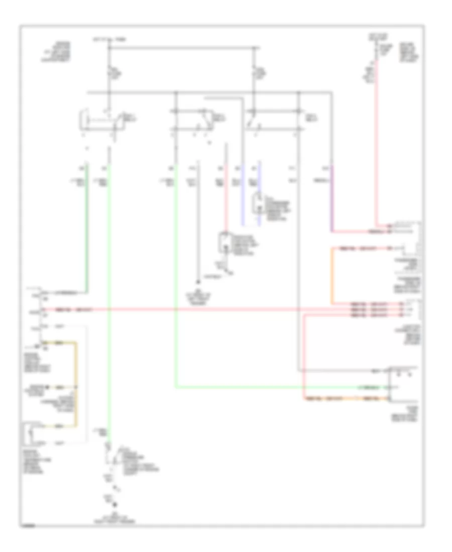
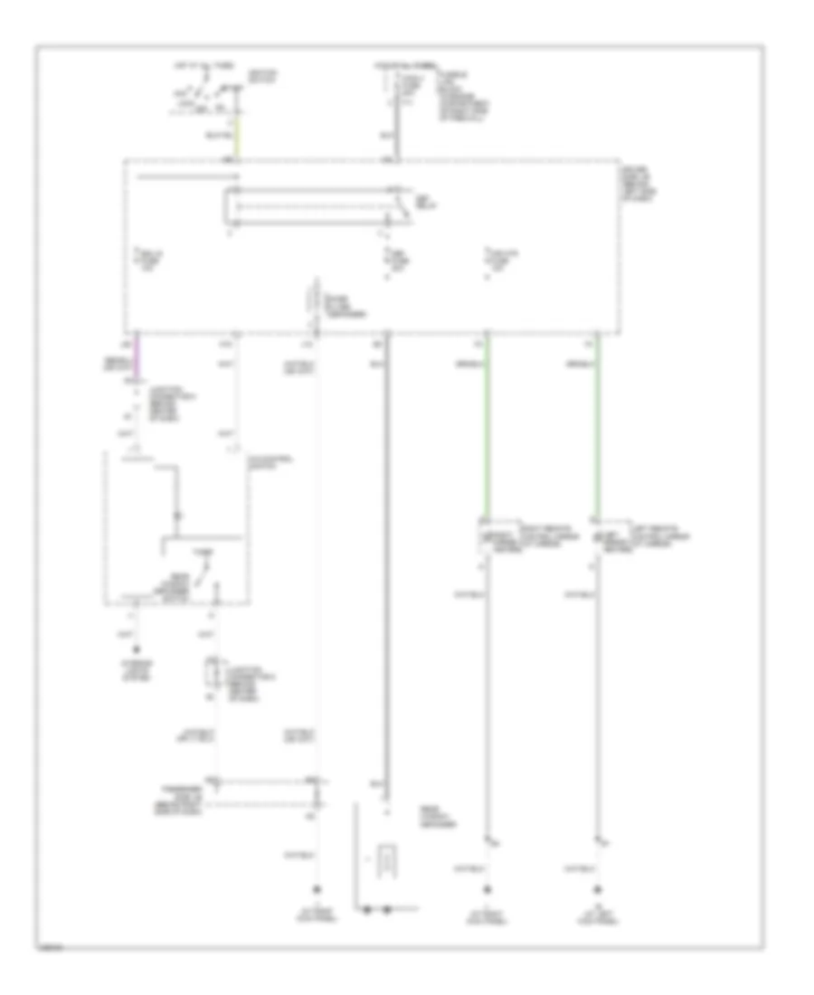
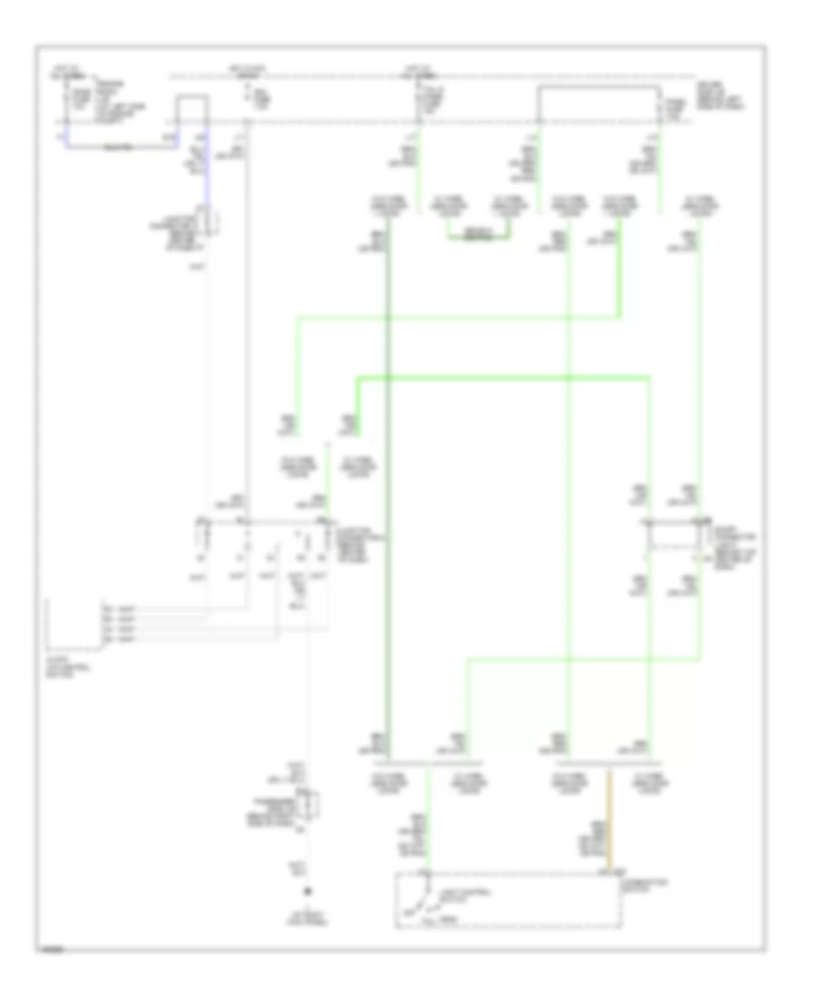
COOLING FAN
Cooling Fan Wiring Diagram for Toyota RAV4 2005
List of elements for Cooling Fan Wiring Diagram for Toyota RAV4 2005:
- A/c condenser fan motor (behind left side of radiator)
- A/c single pressure switch (at right front corner of engine compt)
- Acmg
- Cds fuse 30a
- Diode (fan) (behind right side of dash)
- Driver side j/b (behind left side of dash)
- Ea (at front of right front fender)
- Ed (at front of left front fender)
- Engine control module (behind right side of dash)
- Engine controls system
- Engine coolant temperature sensor (on rear of engine)
- Engine room r/b (at left side of engine compartment)
- F10
- F11
- Fan
- Fan 1 relay
- Fan 2 relay
- Fan 3 relay
- G10
- Gauge fuse 10a
- Hot at all times
- Hot in on or start
- I2 (in dash harness, behind right side of dash)
- Junction connector 4 (behind center of dash)
- Passenger side j/b (behind right side of dash)
- Passenger side j/b ecu
- Radiator fan motor (behind left side of radiator)
- Rdi fuse 30a
- Thw
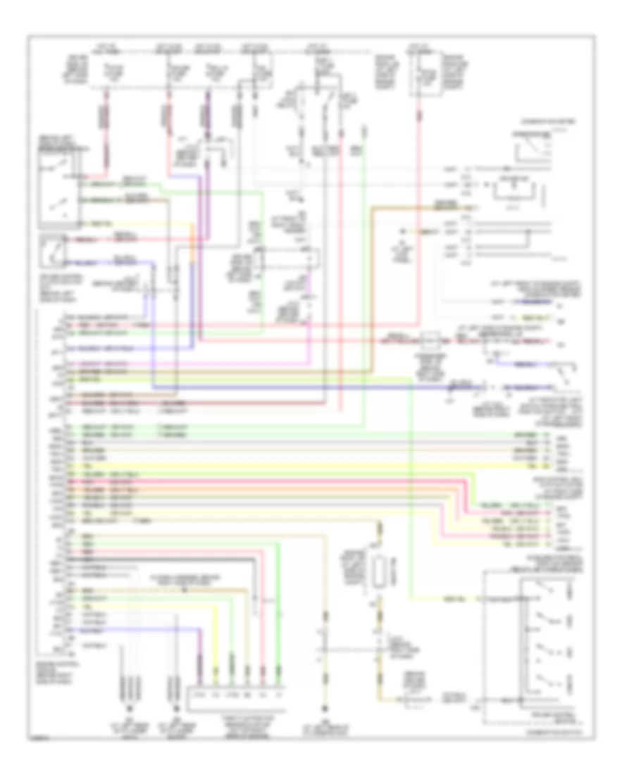
CRUISE CONTROL
Cruise Control Wiring Diagram for Toyota RAV4 2005
List of elements for Cruise Control Wiring Diagram for Toyota RAV4 2005:
- (at left front of engine compt)
- (at left front of engine compt) vehicle speed sensor (combination meter)
- (at left side of engine compt) engine room j/b
- (behind center of dash) j/c 4
- (behind left side of dash) stoplight switch
- (in dash harness, behind right side of dash) i2
- (or pnk)
- +bm
- +res
- -set
- A/t
- A/t indicator light switch (park/neutral (a/t)
- Accelerator pedal position sensor (below left side of dash)
- Batt
- C12
- C13
- C14
- C15
- C20
- Cancel
- Ccs
- Combination meter
- Combination switch
- Cruise control clutch switch (m/t) (behind left side of dash)
- Cruise control switch
- Cruise ind
- Driver side j/b (behind left side of dash)
- E01
- E02
- E03
- E04
- Ea (at front of right front fender)
- Eb (at left rear of cylinder block)
- Ec (at left rear of cylinder head)
- Ecu ig fuse 10a
- Efi 1 fuse 20a
- Efi 2 fuse 5a
- Efi main relay
- Eng+
- Eng-
- Engine control module (behind right side of dash)
- Engine room j/b (at left side of engine compt)
- Engine room r/b (at left side of engine compt)
- Eom
- Ep1
- Ep2
- Epa
- Epa2
- Etcs fuse 10a
- G10
- G11
- Gauge fuse 10a
- Ge01
- Hot at all times
- Hot in on or start
- Ie (at left kick panel)
- Ig+
- Ig2 fuse 10a
- Igsw
- J/c 4 (behind center of dash)
- J/c 5 (behind center of dash)
- J/c 6 (behind right side of dash)
- J/c 7 & 8 (behind right side of dash)
- J26
- J28
- M/t
- Me01
- Mrel
- Nca
- Neo
- On/off
- Passenger side j/b (behind right side of dash)
- Pnk
- Position switch)
- Red
- Short pin
- Skid control ecu with actuator (at right side of engine compt)
- Spd
- Speedometer
- St1-
- Stop fuse 10a
- Stp
- Throttle position sensor & motor (on top right rear of engine)
- Trc+
- Trc-
- Vcp1
- Vcp2
- Vcpa
- Vpa
- Vpa1
- Vpa2
- Vta1
- Vta2
DEFOGGERS
Defoggers Wiring Diagram for Toyota RAV4 2005
List of elements for Defoggers Wiring Diagram for Toyota RAV4 2005:
- A/c control switch
- Acc
- Def fuse 20a
- Def relay
- Driver side j/b (behind left side of dash)
- Ecu ig fuse 10a
- F11
- Fusible link block (in engine compartment, on right side of firewall)
- Hot at all times
- Ie (at left kick panel)
- Ignition switch
- Ii (at right kick panel)
- Interior lights system
- J12
- J28
- Junction connector 5 (behind center of dash)
- Left mirror heater
- Left remote control mirror (at mirror)
- Lock
- M15
- Main 3 fuse 80a
- Mir htr fuse 10a
- Noise filter (defogger)
- On off
- Passenger side j/b (behind right side of dash)
- Rear window defogger
- Rear window defogger switch
- Right mirror heater
- Right remote control mirror (at mirror)
- Start
- Timer
ENGINE PERFORMANCE
2.4L
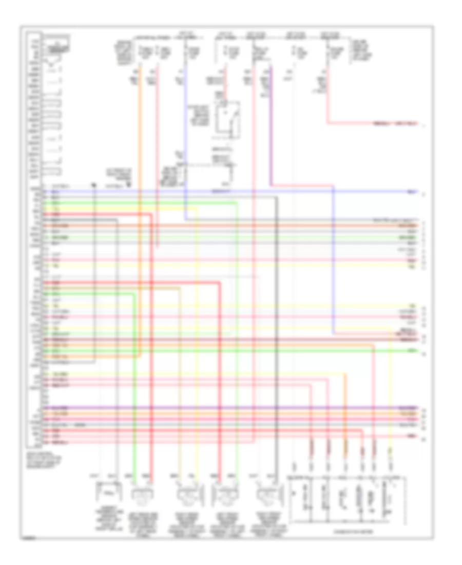
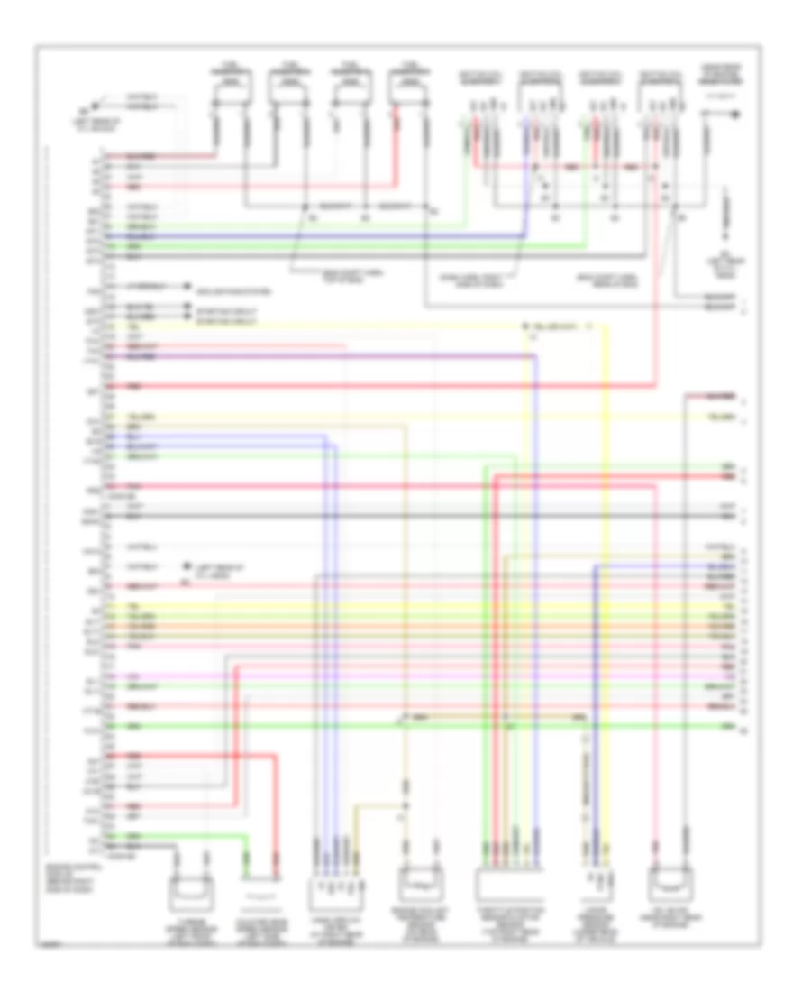
2.4L, Engine Performance Wiring Diagram (1 of 5) for Toyota RAV4 2005
List of elements for 2.4L, Engine Performance Wiring Diagram (1 of 5) for Toyota RAV4 2005:
- (dash harn, right side of dash)
- (eng compt harn, rear of eng)
- (eng compt harn, top of eng)
- (left rear of cyl block)
- (left rear of cyl head)
- (near rear of engine) noise filter
- A1a+
- A1a-
- Ccv
- Conn e5
- Conn e6
- Cooling fans system
- Counter gear speed sensor (left side of eng compt)
- Dsl
- E01
- E02
- E04
- E2g
- Ec (left rear of cyl head)
- Eknk
- Engine control module (behind right side of dash)
- Engine coolant temperature sensor (on rear of engine)
- Evg
- Fan
- Fuel injector 1
- Fuel injector 2
- Fuel injector 3
- Fuel injector 4
- Gnd
- Ha1a
- Ht1b
- Igf
- Igf1
- Ignition coil & igniter 1
- Ignition coil & igniter 2
- Ignition coil & igniter 3
- Ignition coil & igniter 4
- Igt
- Igt1
- Igt2
- Igt3
- Igt4
- Knk1
- Mass airflow meter (at right rear of engine)
- Nc+
- Nc-
- Nsw
- Nt+
- Nt-
- O1b-
- Ox1b
- Pnk
- Prg
- Ptnk
- Red
- Sl1+
- Sl1-
- Sl2+
- Sl2-
- Slt+
- Slt-
- Sta
- Starting circuit
- Tha
- Tho1
- Throttle position sensor & motor sensor (top right rear of engine)
- Thw
- Turbine speed sensor (left front of eng compt)
- Vapor pressure sensor (under rear of vehicle)
- Vcc
- Vsv (evap) (near right rear of engine)
- Vta1
- Vta2
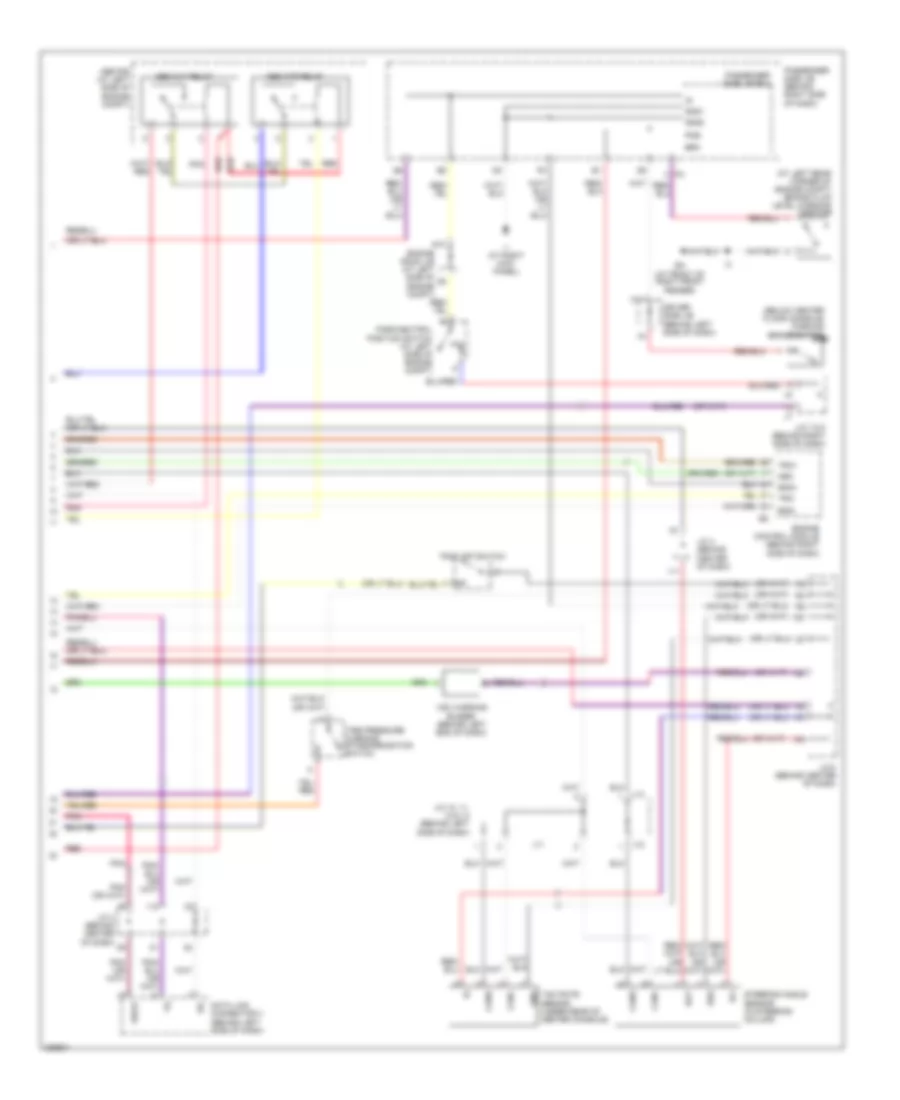
2.4L, Engine Performance Wiring Diagram (2 of 5) for Toyota RAV4 2005
List of elements for 2.4L, Engine Performance Wiring Diagram (2 of 5) for Toyota RAV4 2005:
- (in exhaust system
- Af+
- Af-
- Air fuel ratio sensor (bank 1, sensor 1) (rear of eng)
- Bk (rear of left quarter- panel)
- C/opn relay
- D12
- Dsl
- E4 (eng compt harn, rear of eng)
- Ea (front of right front fender)
- Eb (left rear of cylinder block)
- Efi 1 fuse 20a
- Efi 2 fuse 5a
- Efi 3 fuse 10a
- Efi main relay
- Electronically controlled transmission solenoid (on left front of eng compt)
- Engine room j/b (at left side of engine compt)
- Fuel pump
- G11
- G12
- Heated oxygen sensor (bank 1, sensor 2)
- Hot at all times
- Ig2 relay
- Ign fuse 15a
- J/c 6 (behind right side of dash)
- Nca
- Nca a
- Pnk
- Red
- Sl1+
- Sl1-
- Sl2+
- Sl2-
- Slt+
- Slt-
- Tho
- Vsv (canister closed valve) (near right rear of engine)
2.4L, Engine Performance Wiring Diagram (3 of 5) for Toyota RAV4 2005
List of elements for 2.4L, Engine Performance Wiring Diagram (3 of 5) for Toyota RAV4 2005:
- (dash harn, right side of dash)
- +bm
- Ac1
- Acmg
- Air conditioning system
- Anti-theft system
- Ccs
- Conn e7
- Cruise control system
- Driver side j/b (behind left side of dash)
- Eb (left rear of cylinder block)
- Engine control module (behind right side of dash)
- Engine room r/b (left side of eng compt)
- Etcs fuse 10a
- Hot at all times
- Imi
- Imo
- J/c 5 (behind center of dash)
- J/c 6 (behind right side of dash)
- Knock sensor (on top center of engine)
- Nca
- Odlp
- Oilw
- Red
- Red (or pnk)
- Spd
- St1-
- Stop light switch (behind left side of dash)
- Stp
- System conditioning air
- Thwo
2.4L, Engine Performance Wiring Diagram (4 of 5) for Toyota RAV4 2005
List of elements for 2.4L, Engine Performance Wiring Diagram (4 of 5) for Toyota RAV4 2005:
- A/t oil temp ind
- C13
- C14
- C15
- Combination meter
- Cruise control system (m/t)
- Driver side j/b (behind left side of dash)
- E17
- Hot in on or start
- Ig2 fuse 10a
- J/c 4 (behind center of dash)
- J/c 7, j/c 8 (behind right side of dash)
- J26
- Malfunction ind
- O/d off ind
- Red
2.4L, Engine Performance Wiring Diagram (5 of 5) for Toyota RAV4 2005
List of elements for 2.4L, Engine Performance Wiring Diagram (5 of 5) for Toyota RAV4 2005:
- (behind right side of dash)
- (front of engine) camshaft timing oil control valve
- (left rear of cylinder block)
- (left rear of cylinder head)
- (on front of engine) crankshaft position sensor
- (on rear of engine) camshaft position sensor (right)
- (under center of vehicle) vsv (pressure switching valve)
- A/t indicator light switch (at left front of eng compt)
- Accelerator pedal position sensor (below left side of dash)
- Batt
- Computer data lines system
- Conn e4
- Conn e8
- Data link connector 3 (behind left side of dash)
- Driver side j/b (behind left side of dash)
- E03
- Els
- Eng+
- Eng-
- Engine control module (behind right side of dash)
- Engine room j/b (left side of eng compt)
- Engine room j/b (left side of engine compt)
- Eom
- Ep1
- Ep2
- Epa
- Epa2
- F/ps
- G10
- G2+
- Gauge fuse 10a
- Ge01
- Hot in on or start
- I2 (behind dash harn, right side of dash)
- Igsw
- Ii (right kick panel)
- J/c 4 (behind center of dash)
- J/c 5 (behind center of dash)
- J/c 6
- J/c 6 (behind right side of dash)
- Me01
- Mrel
- Nca
- Ne+
- Ne-
- Neo
- O/d main switch
- Oc1+
- Oc1-
- Odms
- Park/neutral position switch
- Passenger side j/b
- Passenger side j/b (behind right side of dash)
- Pnk
- Power steering oil pressure switch (near front of engine)
- Psw
- Ptnk
- Red
- Seats system
- Short pin
- Sil
- Skid control ecu with actuator (right side of eng compt)
- Tach
- Tbp
- Trc+
- Trc-
- Vcp1
- Vcp2
- Vcpa
- Vpa
- Vpa1
- Vpa2
- Wsfe
EXTERIOR LIGHTS
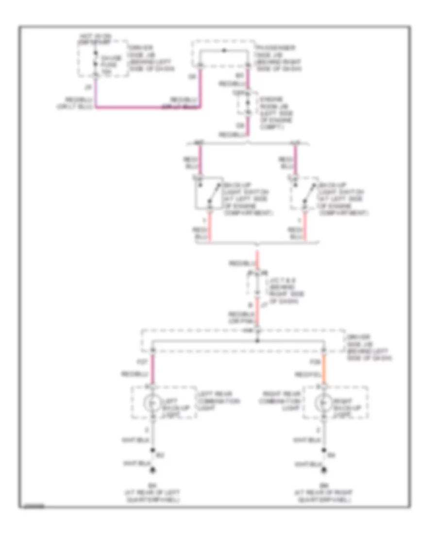
Back-up Lamps Wiring Diagram for Toyota RAV4 2005
List of elements for Back-up Lamps Wiring Diagram for Toyota RAV4 2005:
- A/t
- Back-up light switch (at left side of engine compartment)
- Bk (at rear of left quarterpanel)
- Bm (at rear of right quarterpanel)
- Driver side j/b (behind left side of dash)
- Engine room j/b (left side of engine compt)
- F27
- F28
- G10
- Gauge fuse 10a
- Hot in on or start
- J/c 7 & 8 (behind right side of dash)
- Left back-up light
- Left rear combination light
- M/t
- Passenger side j/b (behind right side of dash)
- Right back-up light
- Right rear combination light
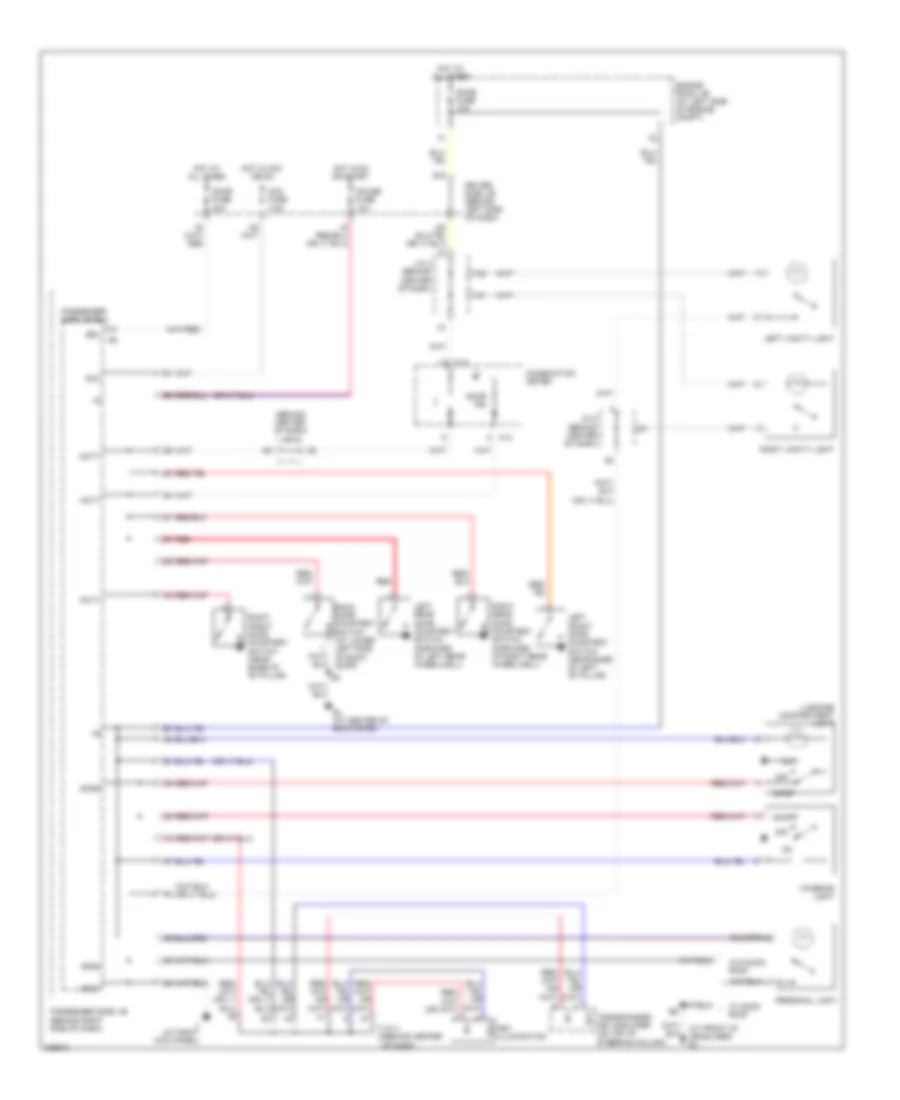
Exterior Lamps Wiring Diagram (1 of 2) for Toyota RAV4 2005
List of elements for Exterior Lamps Wiring Diagram (1 of 2) for Toyota RAV4 2005:
- (behind left side of dash) driver side j/b
- (or pnk)
- Bk (at rear of left quarterpanel)
- Bl (at center of back door)
- Bm (at rear of right quarterpanel)
- Combination switch
- Driver side j/b (behind left side of dash)
- Ecu ig fuse 10a
- Ehw
- Engine room j/b (at left side of engine compartment)
- F18
- F23
- F24
- F25
- Gnd
- Haz fuse 10a
- Hazard switch (a/c control switch)
- High mounted stop light
- Hot at all times
- Hot in on or start
- Ie (at left kick panel)
- J12
- Junction connector 4 (behind center of dash)
- L15
- Left
- Left noise filter (behind left rear quarterpanel)
- Left rear combination light
- Left rear turn signal light
- Left stop light
- Left tail- light
- Right
- Right noise filter (behind right rear quarterpanel)
- Right rear combination light
- Right rear turn signal light
- Right stop light
- Right tail- light
- Stop fuse 10a
- Stop light switch (behind left side of dash)
- Turn signal flasher relay (behind left side of dash)
- Turn signal switch
Exterior Lamps Wiring Diagram (2 of 2) for Toyota RAV4 2005
List of elements for Exterior Lamps Wiring Diagram (2 of 2) for Toyota RAV4 2005:
- (behind left side of dash) (w/ wireless door lock control) taillight relay
- (or pnk)
- Bl (at center of back door)
- C13
- C15
- C16
- Combination meter
- Combination switch
- Dome fuse 10a
- Driver side j/b (behind left side of dash)
- Ea (at front of right front fender)
- Ed (at front of left front fender)
- Engine room j/b (at left side of engine compartment)
- Gauge fuse 10a
- Gnd1
- Gnd2
- Head
- Hot at all times
- Hot in or or start
- Ii (at right kick panel)
- J/c 4 (behind center of dash)
- J/c 5 (behind center of dash)
- J10
- L14
- L17
- Left front parking light
- Left front turn signal light
- Left turn signal indicator light
- License plate light
- Light control switch
- Off
- Panel fuse 7.5a
- Passenger side j/b (behind right side of dash)
- Passenger side j/b ecu
- Right front parking light
- Right front turn signal light
- Right turn signal indicator light
- Short connector (light) (w/ wireless door lock control) (behind top center of dash)
- Tail
- Tail & panel fuse 15a
- Tail fuse 7.5a
- W/ wireless door lock control
- W/o wireless door lock control
GROUND DISTRIBUTION
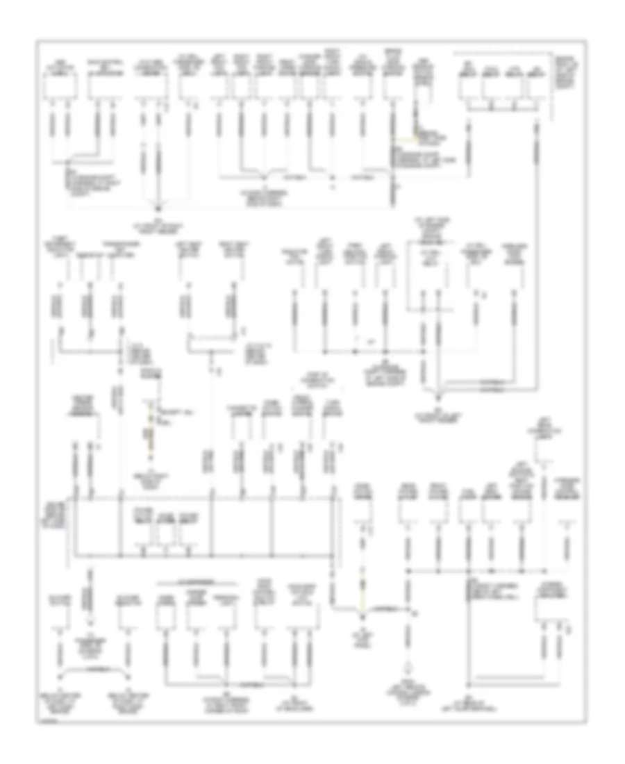
Ground Distribution Wiring Diagram (1 of 2) for Toyota RAV4 2005
List of elements for Ground Distribution Wiring Diagram (1 of 2) for Toyota RAV4 2005:
- (at left side of engine compt) engine room r/b
- (w/ drl) h-lp relay
- (w/ drl) passenger side j/b ecu
- (w/o abs) combination meter
- A/c single pressure switch
- A/t
- Abs actuator & ecu
- Abs decele- ration sensor shield
- B2 (in body harness, above left rear wheelwell)
- B6 (in roof harness, at right front corner of roof)
- Bj (at front of headliner)
- Bk (at rear of left quarterpanel)
- Blower resistor
- Blower switch
- Brake fluid level warning switch
- C12
- C13
- C16
- C18
- Center airbag sensor assembly
- Cigarette lighter
- Combi- nation meter
- Combi- nation switch
- Driver side j/b (behind left side of dash)
- E1 (in engine compt harness, at right side of engine compt)
- E5 (in engine compt harness, at left side of engine compt)
- Ea (at front of right front fender)
- Ed (at front of left front fender)
- Efi main relay
- Engine room j/b (at left side of engine compt)
- F10
- Fan 2 relay
- From left remote control mirror (diagram 2 of 2)
- Front power outlet
- Front wiper & washer switch
- Front wiper motor
- Fuel pump
- Garage door opener
- Htr relay
- I3 (behind right side of dash)
- I3 (in dash harness, behind right side of dash)
- Ie (at left kick panel)
- If (below center of dash, at left dash brace)
- Ig (below center of dash, at right dash brace)
- Ig2 relay
- Ih (below right side of dash)
- Inner mirror
- J/c 14 & 15 (behind center of dash)
- J/c 5 (behind center of dash)
- J12
- J14
- J15
- L15
- L18
- L19
- L21
- Left buckle switch & seat position air bag sensor
- Left front fog light
- Left front parking light
- Left front turn signal light
- Left rear combination light
- Left seat heater
- Left seat heater switch
- Moon roof control switch & relay
- Moon roof motor & limit switch
- Nca
- Noise filter
- Park/ neutral position switch
- Part of combination switch
- Personal light
- Power outlet relay
- Power relay
- R16 (jbl)
- R3 (except jbl)
- Radiator fan motor
- Radio & player
- Rear power outlet
- Rheostat
- Right front fog light
- Right front parking light
- Right front turn signal light
- Right seat heater switch
- S21
- Skid control ecu w/ actuator
- Stereo component amplifier
- Theft deterrent indicator light
- To passenger side j/b (diagram 2 of 2)
- Transponder key computer
- Turn signal switch
- W/ moon roof
- Washer level warning sensor
- Wireless door control receiver
- Wireless door lock buzzer
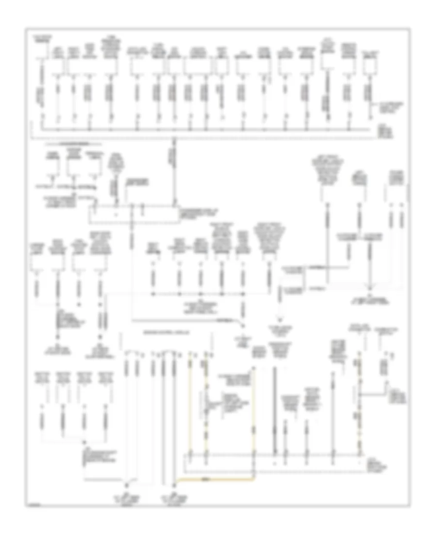
Ground Distribution Wiring Diagram (2 of 2) for Toyota RAV4 2005
List of elements for Ground Distribution Wiring Diagram (2 of 2) for Toyota RAV4 2005:
- (2wd) trac off switch
- (m/t) clutch start switch
- (w/o moon roof)
- A/c amplifier
- A/c control switch
- Air fuel ratio sensor (bank 1 sensor 1) shield
- B1 (in body harness, at left front door)
- B3 (in body harness, at center of back door)
- B4 (in body harness, above right rear wheelwell)
- B6 (in roof harness, at right front corner of roof)
- Back door courtesy switch
- Back door key lock & unlock switch & back door lock motor
- Bl (at center of back door)
- Bm (at rear of right quarterpanel)
- C13
- C20
- Camshaft position sensor shield
- Combi- nation meter
- Combination switch
- Crankshaft position sensor shield
- Data link connector
- E3 (in engine compt harness, at rear of engine)
- Eb (at left rear of cylinder block)
- Ec (at left rear of cylinder head)
- Engine control module
- Engine room j/b (at left side of engine compt)
- From driver side j/b (diagram 1 of 2)
- Garage door opener
- Heated oxygen sensor (bank 1 sensor 2) shield
- High mounted stop light
- I2 (in dash harness, behind right side of dash)
- Ignition coil & ignitor
- Ii (at right kick panel)
- Inner mirror
- J/c 4 (behind center of dash)
- J/c 5 (behind center of dash)
- J/c 6 (behind right side of dash)
- Knock sensor shield
- Left front door key lock & unlock switch/ door unlock detection switch & door lock motor
- Left remote control mirror
- Left vanity light
- License plate light
- Nca
- O/d main switch
- Passenger side j/b (behind right side of dash)
- Passenger side j/b ecu
- Personal light
- Power window master switch
- Remote control mirror switch
- Right front buckle switch & seat belt warning occupant detection sensor
- Right front door key lock & unlock switch/ door unlock detection switch & door lock motor
- Right front door lock control switch
- Right rear combination light
- Right remote control mirror
- Right seat heater
- Right vanity light
- Shift lock ecu
- Short pin
- Steering angle sensor
- Taillight relay
- Tire pressure warning standard- ization switch
- To splice b2 (diagram 1 of 2)
- Turn signal flasher relay
- Unlock warning switch
- W/ power windows
- W/ wireless door lock control
- W/o power windows
- Yaw rate sensor
HEADLIGHTS
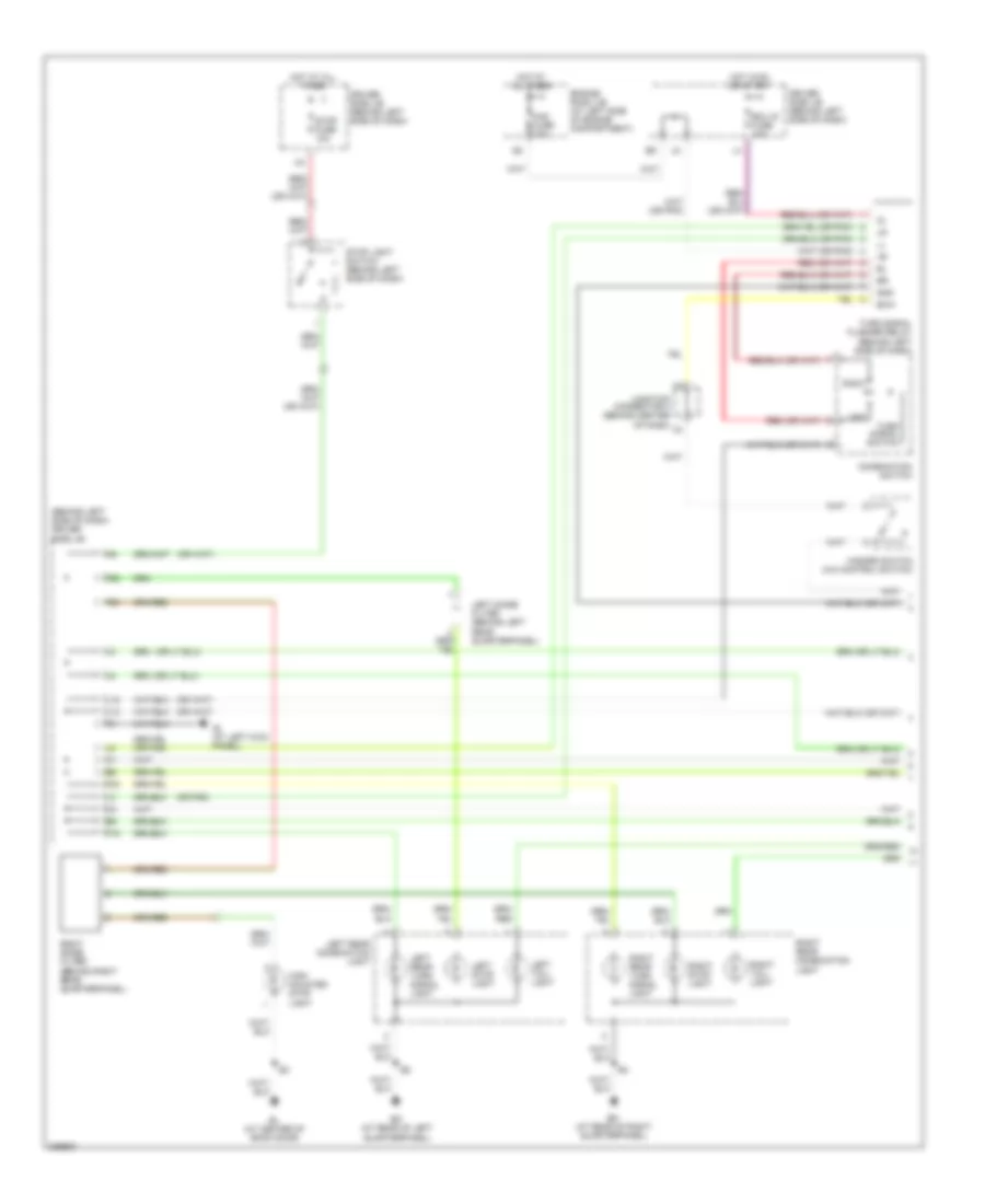
Headlights Wiring Diagram, with DRL for Toyota RAV4 2005
List of elements for Headlights Wiring Diagram, with DRL for Toyota RAV4 2005:
- (behind left side of dash) driver side j/b
- C12
- C13
- C16
- Combination meter
- Combination switch
- Dimmer switch
- Dome fuse 10a
- Driver side j/b (behind left side of dash)
- Drl1
- Drl2
- E29
- E30
- Ea (at front of right front fender)
- Ed (at front of left front fender)
- Engine room j/b (at left side of engine compt)
- Engine room r/b (at left side of engine compt)
- Flash
- Foglight switch
- Fogs
- Fr fog fuse 15a
- Fr fog relay
- Fusible link block (in engine compt, on right side of firewall)
- Gauge fuse 10a
- Gnd1
- Gnd2
- H-lp left fuse 15a
- H-lp right fuse 15a
- Head
- High
- High beam indicator
- Hot at all times
- Hot in on or start
- Ie (at left kick panel)
- Ii (at right kick panel)
- J/c 1& 2 (behind left side of dash)
- J/c 4 (behind center of dash)
- J/c 5 (behind center of dash)
- J1 e
- J10
- J15
- J17
- J2 d
- L14
- L17
- L18
- Left front fog light
- Left headlamp
- Light control switch
- Low
- M11
- Main 4 fuse 80a
- Off
- Panel fuse 7.5a
- Parking brake switch (below center floor console)
- Passenger side j/b (behind right side of dash)
- Passenger side j/b ecu
- Pkb
- Red
- Right front fog light
- Right headlamp
- Short connector (light) (behind top center of dash)
- Tail
- Tail & panel fuse 15a
- W/ wireless door lock control
- W/o wireless door lock control
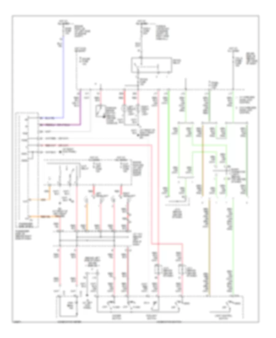
Headlights Wiring Diagram, without DRL for Toyota RAV4 2005
List of elements for Headlights Wiring Diagram, without DRL for Toyota RAV4 2005:
- (at front of right front fender) ea
- (at right kick panel) ii
- (behind left side of dash) driver side j/b
- C12
- C13
- C16
- Combination meter
- Combination switch
- Dimmer switch
- Dome fuse 10a
- Driver side j/b (behind left side of dash)
- E j2
- E29
- E30
- Ed (at front of left front fender)
- Engine room j/b (at left side of engine compt)
- Engine room r/b (at left side of engine compt)
- Flash
- Foglight switch
- Fogs
- Fr fog fuse 15a
- Fr fog relay
- Fusible link block (in engine compt, on right side firewall)
- Gauge fuse 10a
- Gnd1
- Gnd2
- H-lp left fuse 15a
- H-lp relay
- H-lp right fuse 15a
- Head
- High
- High beam ind
- Hlp
- Hot at all times
- Hot in on or start
- Ie (at left kick panel)
- J/c 1 & 2 (behind left side of dash)
- J/c 4 (behind center of dash)
- J/c 5 (behind center of dash)
- J1 e
- J10
- J15
- J17
- J2 d
- L14
- L17
- L18
- Left front fog light
- Left headlight
- Light control switch
- Low
- M11
- Main 4 fuse 80a
- Off
- Panel fuse 7.5a
- Parking brake switch (below center floor console)
- Passenger side j/b (behind right side of dash)
- Passenger side j/b ecu
- Pkb
- Red
- Right front fog light
- Right headlight
- Short connector (light) (behind top center of dash)
- Tail
- Tail & panel fuse 15a
- W/ wireless door lock control
- W/o wireless door lock control
HORN
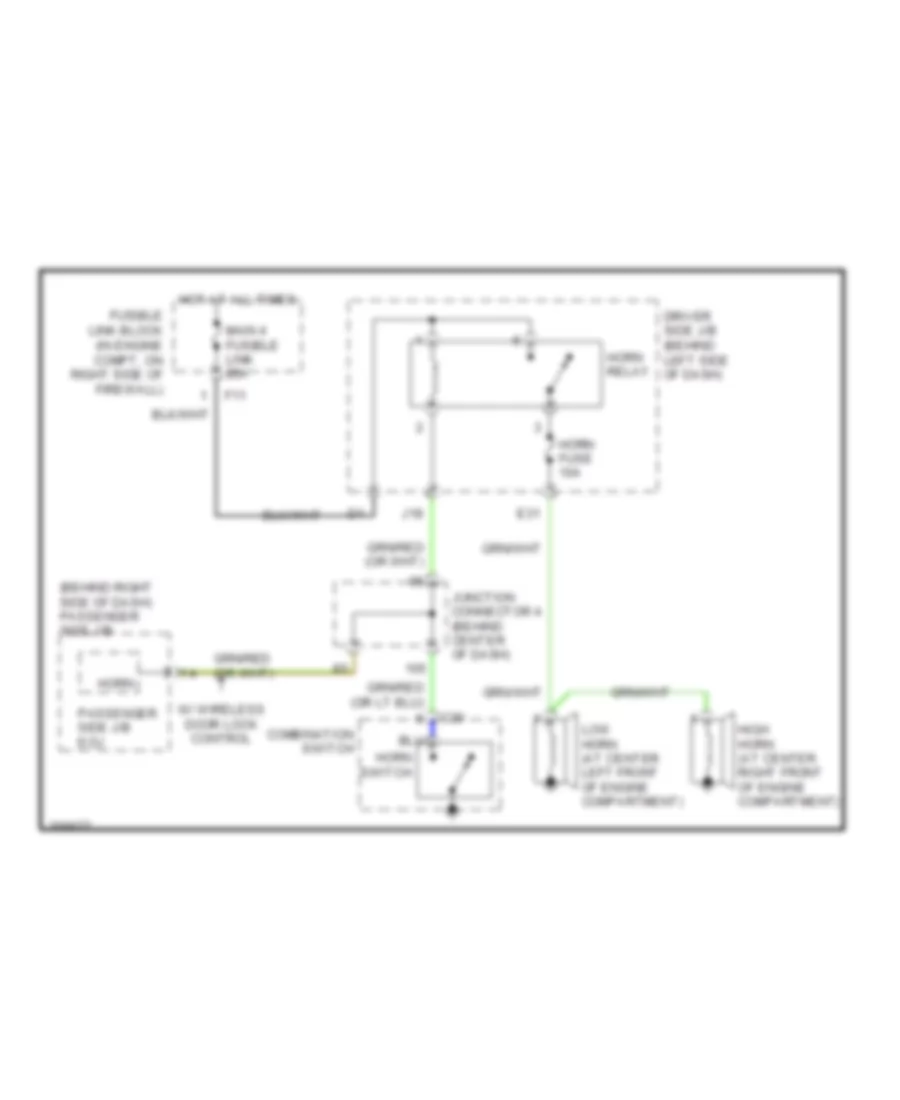
Horn Wiring Diagram for Toyota RAV4 2005
List of elements for Horn Wiring Diagram for Toyota RAV4 2005:
- (behind right side of dash) passenger side j/b
- C20
- Combination switch
- Driver side j/b (behind left side of dash)
- E31
- F11
- Fusible link block (in engine compt, on right side of firewall)
- High horn (at center right front of engine compartment)
- Horn
- Horn fuse 10a
- Horn relay
- Horn switch
- Hot at all times
- J18
- Junction connector 4 (behind center of dash)
- Low horn (at center left front of engine compartment)
- Main 4 fusible link 80a
- Passenger side j/b ecu
- W/ wireless door lock control
INSTRUMENT CLUSTER
Clock Wiring Diagram for Toyota RAV4 2005
List of elements for Clock Wiring Diagram for Toyota RAV4 2005:
- Acc fuse 7.5a
- C16
- Clock (a/c control switch)
- Combination switch
- Dome fuse 10a
- Driver side j/b (behind left side of dash)
- E16
- Engine room j/b (at left side of engine compt)
- Head
- Hot at all times
- Hot in acc or on
- Ii (at right kick panel)
- J10
- J11
- J20
- Junction connector 4 (behind center of dash)
- Junction connector 5 (behind center of dash)
- L14
- L17
- Light control switch
- Off
- Panel fuse 7.5a
- Passenger side j/b (behind right side of dash)
- Short connector (light) (behind top center of dash)
- Tail
- Tail & panel fuse 15a
- W/ wire- less door locks
- W/o wire- less door locks
Instrument Cluster Wiring Diagram (1 of 2) for Toyota RAV4 2005
List of elements for Instrument Cluster Wiring Diagram (1 of 2) for Toyota RAV4 2005:
- (at front of right front fender)
- A/t oil temp ind
- A10
- A11
- A12
- A13
- A14
- A15
- A16
- A17
- A18
- A19
- A20
- Abs ind
- Air bag ind
- Anti-lock brakes system
- B10
- B11
- B12
- B13
- B14
- B15
- B16
- B17
- B18
- B19
- B20
- Beam ind
- Brake ind
- Buzzer
- C10
- C11
- C12
- C13
- C14
- C15
- C16
- C17
- C18
- C19
- C20
- Charge ind
- Combination meter
- Cruise control system
- Cruise ind
- D10
- D11
- D12
- D13
- D14
- D15
- D16
- D17
- D18
- D19
- D20
- Door ind
- Driver side j/b (behind left side of dash)
- Driver's side seat belt ind
- Ecu-ig fuse 10a
- Engine controls system
- Exterior lights system
- Fuel gauge
- Fuel ind
- Fuel sender
- Fuel sender (sub) (under center rear of vehicle)
- Headlights system
- Hot at all times
- Hot in on or start
- Ie (at left kick panel)
- Illumination
- Interior lights system
- J10
- J28
- Junction connector 5 (behind center of dash)
- Left ind
- Malfunction ind lamp
- Mant redo ind
- O/d off ind
- Oil pressure ind
- Oil pressure switch (on rear of engine)
- Panel fuse 7.5a
- Pnk
- Right ind
- Slip ind
- Speedometer
- Starting/charging system
- Tachometer
- Tire pressure ind
- Trac off ind
- Vsc trac ind
- W/ abs
- W/ drl
- W/ wireless door lock control
- W/o abs
- Warning system
- Washer ind
- Water temperature gauge
- Wiper/washer system
Instrument Cluster Wiring Diagram (2 of 2) for Toyota RAV4 2005
List of elements for Instrument Cluster Wiring Diagram (2 of 2) for Toyota RAV4 2005:
- (behind center of dash) junction connector 4
- Acty
- Back door courtesy switch (at lower left side of back door)
- Bl (at center of back door)
- Brake fluid level warning switch (at left rear corner of engine compt)
- Brk
- Bwrn
- Dcty
- Dome fuse 10a
- Driver side j/b (behind left side of dash)
- E16
- Ea (at front of right front fender)
- Engine control module (behind right side of dash)
- Engine room j/b (at left side of engine compt)
- G10
- Gauge fuse 10a
- Gnd1
- Gnd2
- Hot at all times
- Hot in on or start
- Ig+
- Ig2 fuse 10a
- Ii (at right kick panel)
- J20
- J26
- Junction connector 4 (behind center of dash)
- Junction connector 5 (behind center of dash)
- Ksw
- Left front door courtesy switch (near base of left "b" pillar)
- Left rear door courtesy switch (forward of left rear wheelwell)
- M11
- Parking brake switch (below center floor console)
- Passenger side j/b (behind right side of dash)
- Passenger side j/b ecu
- Pcty
- Pkb
- Pkbj
- Red
- Right front door courtesy switch (near base of "b" pillar)
- Right rear door courtesy switch (forward of right rear wheelwell)
- Spd
- Vehicle speed sensor (combination meter) (at left front of engine compt)
- W/ wireless door lock control
- W/o abs
INTERIOR LIGHTS
Courtesy Lamps Wiring Diagram for Toyota RAV4 2005
List of elements for Courtesy Lamps Wiring Diagram for Toyota RAV4 2005:
- (at front of headliner) bj
- (behind center of dash) j/c 4
- Acc
- Acc fuse 7.5a
- Acty
- Back door courtesy switch (at lower left side of back door)
- Bdl
- Bl (at center of back door)
- C13
- Combination meter
- Dcty
- Dome
- Dome fuse 10a
- Door
- Door fuse 20a
- Driver side j/b (behind left side of dash)
- E16
- Engine room j/b (at left side of engine compt)
- Gauge fuse 10a
- Gnd1
- Gnd2
- Hot at all times
- Hot in acc or on
- Hot in on or start
- Ii (at right kick panel)
- Ill+
- Ill-
- Ind
- Interior light
- J/c 4 (behind center of dash)
- J/c 5 (behind center of dash)
- Key illumination
- Left front door courtesy switch (near base of left "b" pillar)
- Left rear door courtesy switch (forward of left rear wheelwell)
- Left vanity light
- Luggage compartment light
- Off
- Passenger side j/b (behind right side of dash)
- Passenger side j/b ecu
- Pcty
- Personal light
- Red
- Right front door courtesy switch (near base of "b" pillar)
- Right rear door courtesy switch (forward of right rear wheelwell)
- Right vanity light
- Transponder key amplifier (on top of steering column)
- W/ moon roof
- W/o moon roof
Instrument Illumination Wiring Diagram for Toyota RAV4 2005
List of elements for Instrument Illumination Wiring Diagram for Toyota RAV4 2005:
- A/c control switch
- A/t shift lever illum (o/d main switch)
- Ashtray illumination
- Audio system(jbl)
- C13
- C16
- C20
- Cigarette lighter illumination
- Combination illumination (combination meter)
- Driver side j/b (behind left side of dash)
- Except audio system(jbl)
- F j16
- Gnd
- H j17
- Head
- Hot at all times
- Ie (at left kick panel)
- Ill-
- J/c 16 &17 (behind center of dash)
- J/c 5 (behind center of dash)
- J10
- L14
- L17
- Left seat heater switch
- Light control switch (combination switch)
- Off
- Panel fuse 7.5a
- Passenger side j/b (w/ wireless door lock control) (behind right side of dash)
- Passenger side j/b ecu
- R15
- R16
- Radio & player
- Rheostat
- Right seat heater switch
- Short connector (light) (behind top center of dash)
- Swg
- Tail
- Tail & panel fuse 15a
- Trac off switch (w/o power window)
- W/ wireless door lock control
- W/o wireless door lock control
POWER DISTRIBUTION
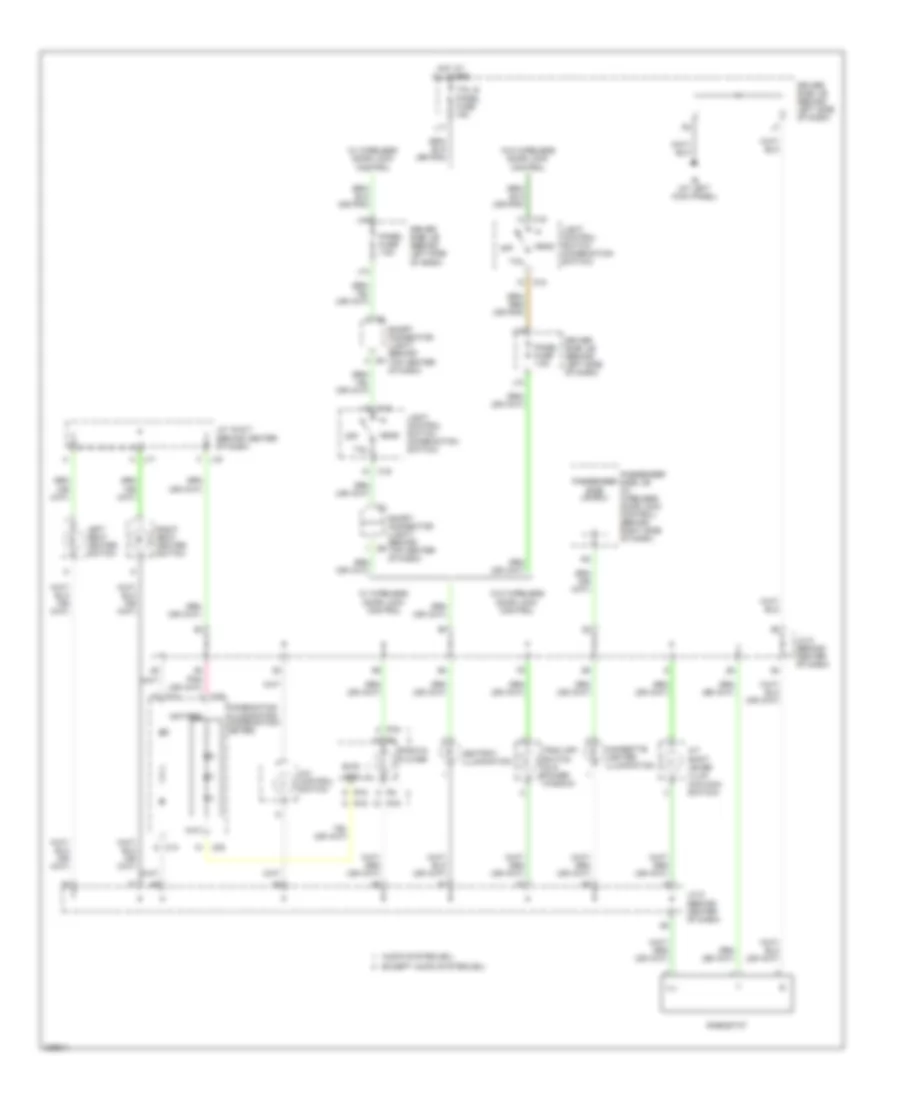
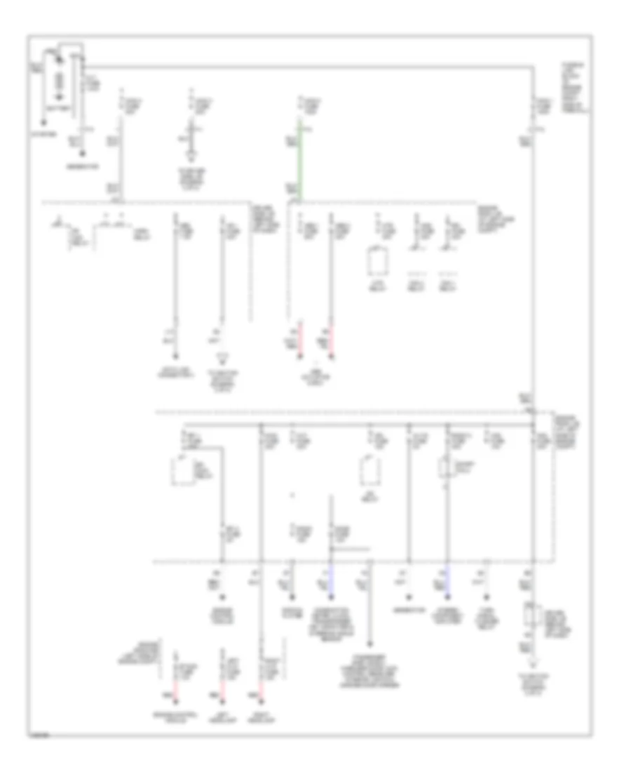
Power Distribution Wiring Diagram (1 of 2) for Toyota RAV4 2005
List of elements for Power Distribution Wiring Diagram (1 of 2) for Toyota RAV4 2005:
- Abs 1 fuse 50a
- Abs 2 fuse 30a
- Abs actuator & ecu
- Alt fuse 140a
- Alt-s fuse 5a
- Am1 fuse 40a
- Am2 fuse 30a
- Battery
- Cds fuse 30a
- Combination meter, clock, transponder key computer & steering angle sensor
- Cut fuse 30a
- Data link connector 3
- Dome fuse 10a
- Driver side j/b (behind left side of dash)
- Efi 1 fuse 20a
- Efi 2 fuse 5a
- Efi main relay
- Engine control module
- Engine room j/b (at left side of engine compt)
- Engine room r/b (left side of engine compt)
- Etacs fuse 10a
- F11
- F12
- F13
- Fan 1 relay
- Fan 3 relay
- Fr fog relay
- Fusible link block (in engine compt, right side of firewall)
- Generator
- Haz fuse 10a
- Horn relay
- Htr fuse 40a
- Htr relay
- Ig2 relay
- Ign fuse 15a
- L13
- Left h-lp fuse 15a
- Left headlamp
- Main 1 fuse 100a
- Main 2 fuse 100a
- Main 3 fuse 80a
- Main 4 fuse 80a
- Main fuse 30a
- Nca
- Obd fuse 7.5a
- Passenger side j/b ecu, wireless door lock control receiver, interior lights & garage door opener
- Radio & player
- Radio 2 fuse 30a
- Radio fuse 15a
- Rdi fuse 30a
- Red
- Right h-lp fuse 15a
- Right headlamp
- Short pin 2
- Starter
- Stereo component amplifier
- To driver side j/b (diagram 2 of 2)
- To ignition switch (diagram 2 of 2)
- Turn signal flasher relay
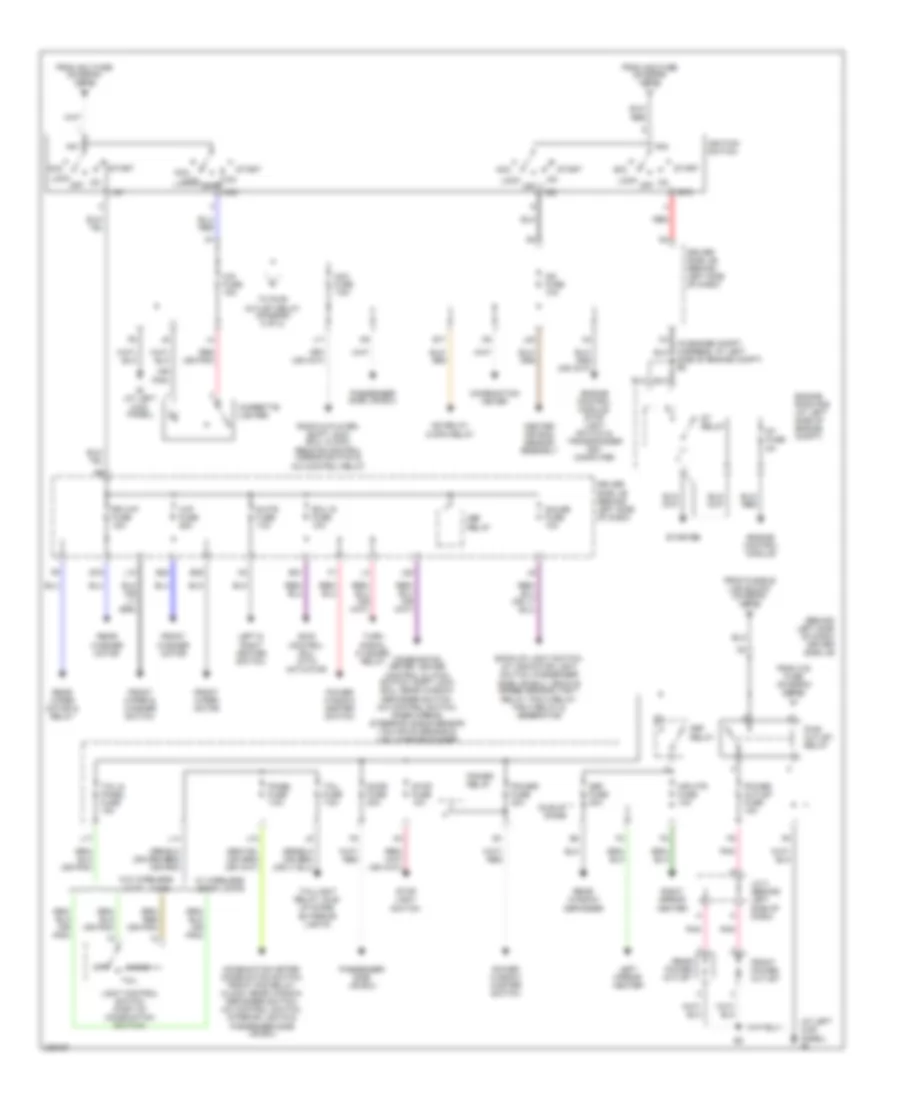
Power Distribution Wiring Diagram (2 of 2) for Toyota RAV4 2005
List of elements for Power Distribution Wiring Diagram (2 of 2) for Toyota RAV4 2005:
- (at left kick panel) ie
- (behind left side of dash) driver side j/b
- (or pnk)
- Acc
- Acc fuse 7.5a
- Am1
- Am2
- Back-up light switch, a/t indicator light switch, passenger side j/b ecu, vehicle speed sensor, fan 1 relay, fan 2 relay, fan 3 relay & generator
- Center air bag sensor assembly
- Cig fuse 15a
- Cigarette lighter
- Combination meter
- Combination meter, combination switch, front fog relay, clock, rear window defogger switch, a/c control switch, interior lights & passenger side j/b ecu
- Combination meter, cruise control clutch switch, shift lock ecu, rear window defogger switch, a/c control switch, inner mirror, steering angle sensor yaw rate sensor & vsc warning buzzer
- Def fuse 20a
- Def relay
- Door fuse 20a
- Driver side j/b (behind left side of dash)
- E17
- E19
- E21
- E22
- E25
- Ecu ig fuse 10a
- Engine control module
- Engine control module, stop light switch & transponder key computer
- Engine room r/b (at left side of engine compt)
- From am1 fuse (diagram 1 of 2)
- From am2 fuse (diagram 1 of 2)
- From cig fuse (diagram 2 of 2)
- From fusible link block (diagram 1 of 2)
- Front power outlet
- Front washer motor
- Front wiper & washer switch
- Front wiper motor
- Gauge fuse 10a
- Head
- Idle-up diode
- Ie (at left kick panel)
- Ig1
- Ig2
- Ig2 fuse 10a
- Ig2 relay, c/opn relay
- Ignition switch
- J/c 3 (behind left side of dash)
- J10
- J11
- J28
- L10
- L14
- L17
- L20
- Left & right heater switch
- Left mirror heater
- Light control switch (part of combination switch)
- Lock
- Mir htr fuse 10a
- Off
- Panel fuse 7.5a
- Passenger side j/b ecu
- Pnk
- Power fuse 30a
- Power outlet fuse 15a
- Power relay
- Power window master switch
- Pwr outlet relay
- Radio & player, shift lock ecu, clock, remote control mirror switch & a/c control relay
- Rear power outlet
- Rear washer motor
- Rear window defogger
- Rear wiper motor & relay
- Red
- Red (or pnk)
- Right mirror heater
- Rr wip fuse 15a
- S-htr fuse 10a
- Side of engine compt) e5
- Skid control ecu with actuator
- St fuse 5a
- St relay
- St2
- Start
- Starter
- Stop fuse 10a
- Stop light switch
- Tail
- Tail & panel fuse 15a
- Tail fuse 7.5a
- Taillight relay, idle- up diode, exterior lights
- To pwr outlet relay (diagram 2 of 2)
- Turn signal flasher relay
- W/ wireless door locks
- W/o wireless door locks
- Wip fuse 25a
POWER DOOR LOCKS
Power Door Locks Wiring Diagram, with Keyless Entry for Toyota RAV4 2005
List of elements for Power Door Locks Wiring Diagram, with Keyless Entry for Toyota RAV4 2005:
- Acc
- Acc fuse 7.5a
- Act+
- Act-
- Actd
- Acty
- Back door courtesy switch (at lower left side of back door)
- Back door lock motor (at lower left side of back door)
- Bdl
- Bl (at center of back door)
- Bzr
- C13
- C14
- Combination meter
- D10
- Dcty
- Dome fuse 10a
- Door fuse 20a
- Driver side j/b (behind left side of dash)
- Ed (at front of left front fender)
- Engine room j/b (at left side of engine compt)
- Exterior lights system
- F15
- F16
- F17
- F20
- F21
- Gauge fuse 10a
- Gnd
- Gnd1
- Horn
- Horns system
- Hot at all times
- Hot in on or acc
- Hot in on or start
- Ie (at left kick panel)
- Ii (at right kick panel)
- J21
- J24
- Ksw
- Left front door courtesy switch (near base of left "b" pillar)
- Left front door lock motor & door unlock detection switch (at rear of left front door)
- Left rear door courtesy switch (forward of left rear wheelwell)
- Left rear door lock motor (at rear of left rear door)
- Lswd
- Lswp
- Passenger side j/b (behind right side of dash)
- Passenger side j/b ecu
- Pcty
- Prg
- Rda
- Red
- Right front door courtesy switch (near base of "b" pillar)
- Right front door lock motor & door unlock detection switch (at rear of right front door)
- Right rear door courtesy switch (forward of right rear wheelwell)
- Right rear door lock motor (at rear of right rear door)
- Tail
- Warning system
- Wireless door control receiver (at left rear side of cargo area)
- Wireless door lock buzzer (at left front of engine compt)
Power Door Locks Wiring Diagram, without Keyless Entry for Toyota RAV4 2005
List of elements for Power Door Locks Wiring Diagram, without Keyless Entry for Toyota RAV4 2005:
- Acc
- Acc fuse 7.5a
- Act+
- Act-
- Actd
- Back door key lock & unlock switch & back door lock motor (at lower left side of back door)
- Bdl
- Bl (at center of back door)
- C12
- C13
- C14
- C17
- C18
- Detect
- Dome fuse 10a
- Door fuse 20a
- Driver side j/b (behind left side of dash)
- Engine room j/b (at left side of engine compt)
- F15
- F16
- F17
- F20
- F21
- Gauge fuse 10a
- Gnd1
- Gnd2
- Hot at all times
- Hot in acc or on
- Hot in on or start
- Ie (at left
- Ie (at left kick panel)
- Ii (at right kick panel)
- J21
- J24
- Kick panel)
- Left front door lock lock control switch (power window master switch)
- Left front door lock motor, door key lock & unlock switch & door unlock detection switch (at rear of left front door)
- Left rear door lock motor (at rear of left rear door)
- Lock
- Lswd
- Lswp
- Passenger side j/b (behind right side of dash)
- Passenger side j/b ecu
- Right front door lock lock control switch
- Right front door lock motor, door key lock & unlock switch & door unlock detection switch (at rear of right front door)
- Right rear door lock motor (at rear of right rear door)
- Ul1
- Ul2
- Ul3
- Unlk
POWER MIRRORS
Electrochromic Mirror Wiring Diagram for Toyota RAV4 2005
List of elements for Electrochromic Mirror Wiring Diagram for Toyota RAV4 2005:
- (at front of headliner) bj
- (at right kick panel) ii
- Driver side j/b (behind left side of dash)
- Ecu ig fuse 10a
- Hot in on or start
- Inner mirror
- J/c 5 (behind center of dash)
- J28
- Passenger side j/b (behind right side of dash)
- W/ moon roof
- W/o moon roof
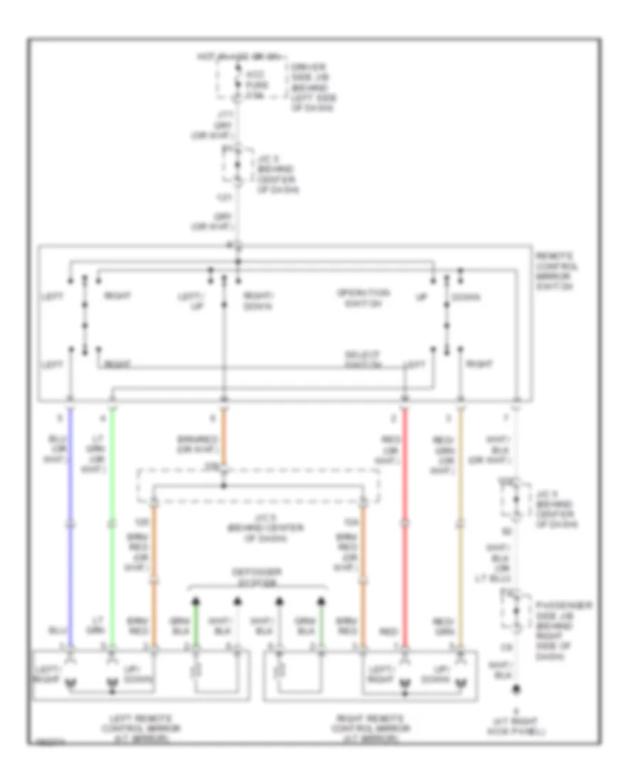
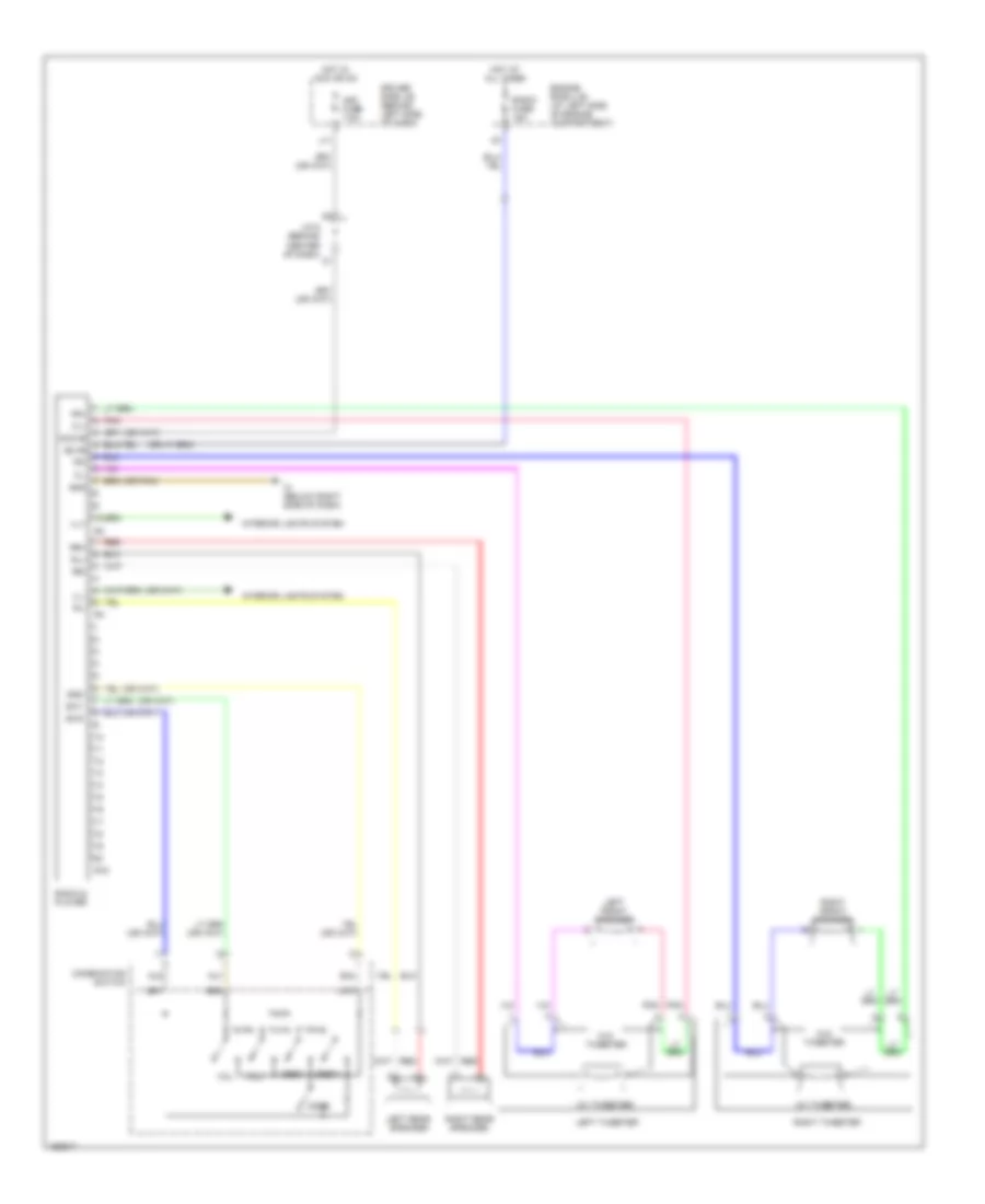
Power Mirrors Wiring Diagram for Toyota RAV4 2005
List of elements for Power Mirrors Wiring Diagram for Toyota RAV4 2005:
- Acc fuse 7.5a
- Defogger system
- Down
- Driver side j/b (behind left side of dash)
- Hot in acc or on
- Ii (at right kick panel)
- J/c 5 (behind center of dash)
- Left
- Left remote control mirror (at mirror)
- Left/ right m
- Left/ up
- Operation switch
- Passenger side j/b (behind right side of dash)
- Red
- Remote control mirror switch
- Right
- Right remote control mirror (at mirror)
- Right/ down
- Select switch
- Up/ down
POWER SEATS
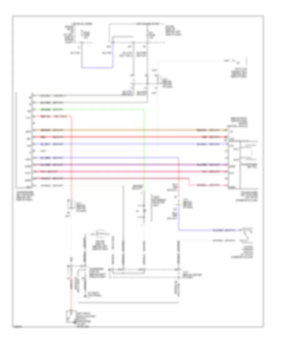
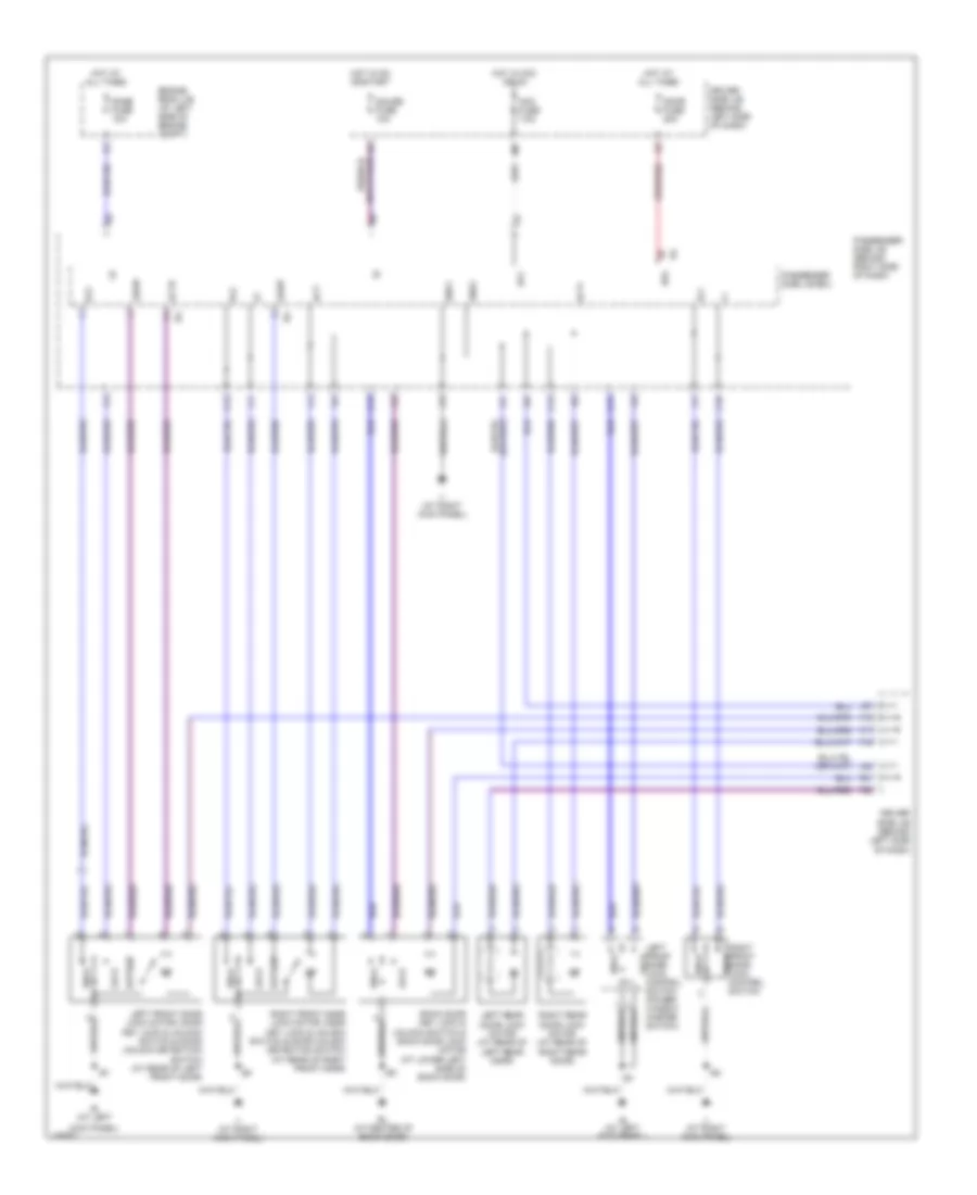
Heated Seats Wiring Diagram for Toyota RAV4 2005
List of elements for Heated Seats Wiring Diagram for Toyota RAV4 2005:
- (under right front seat)
- A j16
- Bk (at rear of left quarter panel)
- Driver side j/b (behind left side of dash)
- E j14
- E j15
- Engine control module (behind right side of dash)
- Engine room j/b (left side of eng compt)
- Hot in on or start
- Ie (at left kick panel)
- Ii (at right kick panel)
- Interior lights system
- J14
- J14 a
- J15
- J15 b
- J15 c
- J17
- Junction connector (behind center of dash)
- Junction connector 14 & 15 (behind center of dash)
- Junction connector 16 & 17 (behind center of dash)
- Left seat heater (at left kick panel)
- Left seat heater switch
- Right seat heater
- Right seat heater switch
- S-htr fuse 10a
- Seat heater diode (behind center of dash)
POWER TOP/SUNROOF
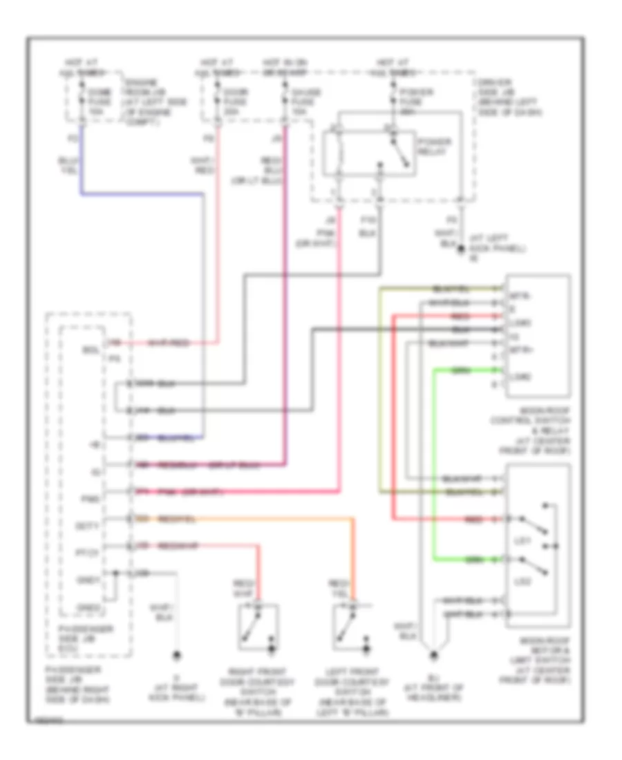
Power Top/Sunroof Wiring Diagram for Toyota RAV4 2005
List of elements for Power Top/Sunroof Wiring Diagram for Toyota RAV4 2005:
- (at left kick panel) ie
- Bdl
- Bj (at front of headliner)
- C10
- Dcty
- Dome fuse 10a
- Door fuse 20a
- Driver side j/b (behind left side of dash)
- Engine room j/b (at left side of engine compt)
- F10
- Gauge fuse 10a
- Gnd1
- Gnd2
- Hot at all times
- Hot in on or start
- Ii (at right kick panel)
- Left front door courtesy switch (near base of left "b" pillar)
- Ls#2
- Ls#3
- Ls1
- Ls2
- Moon roof control switch & relay (at center front of roof)
- Moon roof motor & limit switch (at center front of roof)
- Mtr+
- Mtr-
- Passenger side j/b (behind right side of dash)
- Passenger side j/b ecu
- Pms
- Pnk
- Power fuse 30a
- Power relay
- Ptcy
- Red
- Right front door courtesy switch (near base of "b" pillar)
POWER WINDOWS
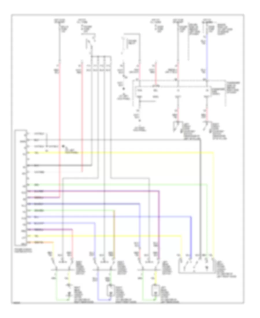
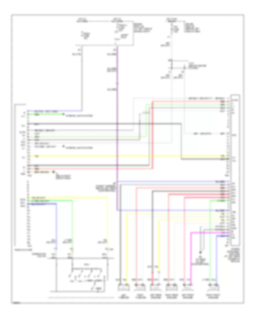
Power Windows Wiring Diagram for Toyota RAV4 2005
List of elements for Power Windows Wiring Diagram for Toyota RAV4 2005:
- Bdl
- Dcty
- Dome fuse 10a
- Door fuse 20a
- Driver side j/b (behind left side of dash)
- Ecu ig fuse 10a
- Engine room j/b (at left side of engine compt)
- F11
- F12
- F13
- F14
- Gauge fuse 10a
- Gnd1
- Gnd2
- Hot at all times
- Hot in on or start
- Ie (at left kick panel)
- Ii (at right kick panel)
- Left front door courtesy switch (near base of left "b" pillar)
- Left front power window motor (at center of left front door)
- Left rear power window control switch
- Left rear power window motor (at center of left rear door)
- Lmt
- Passenger side j/b (behind right side of dash)
- Passenger side j/b ecu
- Pcty
- Pls
- Pms
- Power fuse 30a
- Power relay
- Power window master switch
- Right front door courtesy switch (near base of "b" pillar)
- Right front power window control switch
- Right front power window motor (at center of right front door)
- Right rear power window control switch
- Right rear power window motor (at center of right rear door)
- Rld
- Rlu
- Rrd
- Rru
- Sgnd
RADIO
Radio Wiring Diagram, with JBL for Toyota RAV4 2005
List of elements for Radio Wiring Diagram, with JBL for Toyota RAV4 2005:
- (or pnk)
- +b2
- Acc
- Acc fuse 7.5a
- Au1
- Au2
- B5 (in body harness, behind left rear quarterpanel)
- Bk (at rear of left quarterpanel)
- C20
- Combination switch
- Driver side j/b (behind left side of dash)
- Eau
- Engine room j/b (at left side of engine compt)
- Fl+
- Fl-
- Fr+
- Fr-
- Gnd
- Hot at all times
- Hot in on or acc
- Ih (below right side of dash)
- Ill+
- Ill-
- Interior lights system
- J/c 5 (behind center of dash)
- J11
- Left front speaker
- Left rear speaker
- Left tweeter
- Mode
- Mute
- Nca
- Pnk
- R15
- R16
- Radio & player
- Radio 2 fuse 30a
- Radio fuse 15a
- Red
- Right front speaker
- Right rear speaker
- Right tweeter
- Rl+
- Rl-
- Rr+
- Rr-
- S21
- S22
- Seek+
- Seek-
- Short pin 2
- Sl+
- Sl-
- Sld
- Sr+
- Sr-
- Stereo component amplifier (at left rear corner of vehicle)
- Sw1
- Sw2
- Swg
- Tx+
- Tx-
- Vol+
- Vol-
Radio Wiring Diagram, without JBL for Toyota RAV4 2005
List of elements for Radio Wiring Diagram, without JBL for Toyota RAV4 2005:
- (or pnk)
- (w/ tweeter)
- Acc fuse 7.5a
- Acc+b
- Au1
- Au2
- Bu+b
- Combination switch
- Driver side j/b (behind left side of dash)
- Eau
- Engine room j/b (at left side of engine compartment)
- Fl+
- Fl-
- Fr+
- Fr-
- Gnd
- Hot at all times
- Hot in acc or on
- Ih (below right side of dash)
- Ill+
- Ill-
- Interior lights system
- J/c 5 (behind center of dash)
- J11
- Left front speaker
- Left rear speaker
- Left tweeter
- Mode
- Pnk
- R15
- Radio & player
- Radio fuse 15a
- Red
- Right front speaker
- Right rear speaker
- Right tweeter
- Rl+
- Rl-
- Rr+
- Rr-
- Seek+
- Seek-
- Sw1
- Sw2
- Vol+
- Vol-
- W/o tweeter
SHIFT INTERLOCK
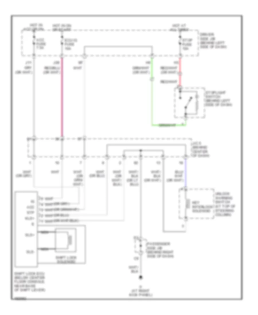
Shift Interlock Wiring Diagram for Toyota RAV4 2005
List of elements for Shift Interlock Wiring Diagram for Toyota RAV4 2005:
- Acc
- Acc fuse 7.5a
- Driver side j/b (behind left side of dash)
- Ecu ig fuse 10a
- Hot at all times
- Hot in acc or on
- Hot in on or start
- Ii (at right kick panel)
- J/c 5 (behind center of dash)
- J11
- J28
- Key interlock solenoid
- Kls+
- Nca
- Passenger side j/b (behind right side of dash)
- Shift lock ecu (below center floor console, near base of shift lever)
- Shift lock solenoid
- Sls+
- Sls-
- Stop fuse 10a
- Stoplight switch (behind left side of dash)
- Stp
- Unlock warning switch (at top of steering column)
STARTING/CHARGING
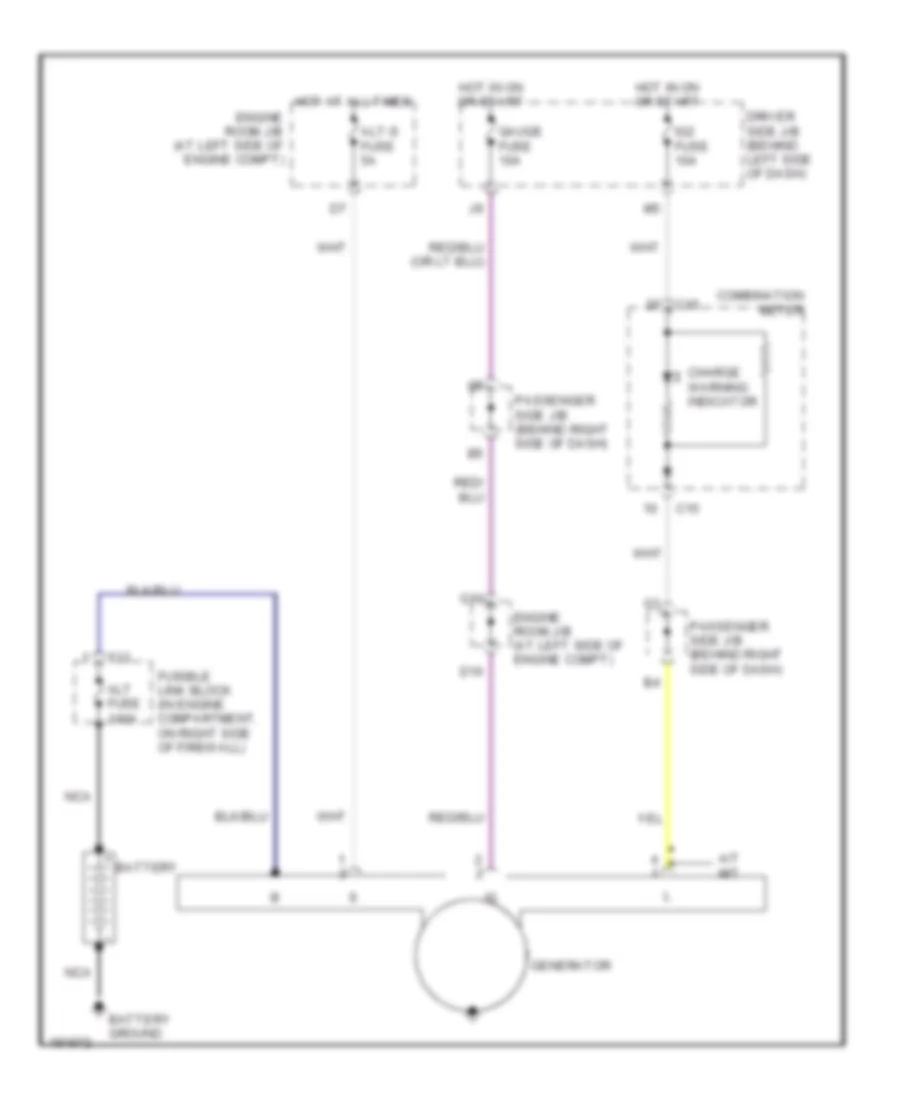
Charging Wiring Diagram for Toyota RAV4 2005
List of elements for Charging Wiring Diagram for Toyota RAV4 2005:
- A/t m/t
- Alt fuse 140a
- Alt-s fuse 5a
- Battery
- Battery ground
- C15
- Charge warning indicator
- Combination meter
- D10
- Driver side j/b (behind left side of dash)
- Engine room j/b (at left side of engine compt)
- F13
- Fusible link block (in engine compartment, on right side of firewall)
- G10
- Gauge fuse 10a
- Generator
- Hot at all times
- Hot in on or start
- Ig2 fuse 10a
- Nca
- Passenger side j/b (behind right side of dash)
Starting Wiring Diagram for Toyota RAV4 2005
List of elements for Starting Wiring Diagram for Toyota RAV4 2005:
- (behind right side of dash) passenger side j/b
- A/t
- Acc
- Am2 fuse 30a
- Battery
- Battery ground
- Clutch start switch (behind left side of dash)
- Driver side j/b (behind left side of dash)
- Ed (at front of left front fender)
- Engine control module (behind right side of dash)
- Engine room j/b (at left side of engine compt)
- Engine room r/b (at left side of engine compt)
- F12
- Fusible link block (in engine compt, on right side of firewall)
- Ignition switch
- Ii (at right kick panel)
- Junction connector 5 (behind center of dash)
- Lock
- M/t
- Main 1 fuse 100a
- Nca
- Nsw
- Off
- P/n
- Park/ neutral position switch (at left front of engine compt)
- Red
- St fuse 5a
- Sta
- Start
- Starter
- Starter relay
SUPPLEMENTAL RESTRAINTS
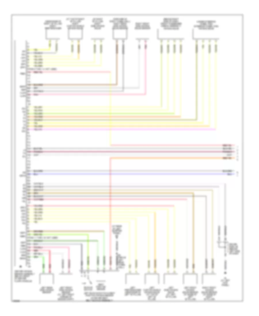
Supplemental Restraints Wiring Diagram (1 of 2) for Toyota RAV4 2005
List of elements for Supplemental Restraints Wiring Diagram (1 of 2) for Toyota RAV4 2005:
- (at rear of left quarter panel) bk
- (at right "b" pillar) right side air bag squib
- (at top of right "b" pillar) right curtain shield air bag squib
- (behind right side of dash) (front passenger airbag assembly) air bag squib
- (forward of right wheelwell) right rear side air bag squib sensor
- (near base of right "b" pillar) right pretensioner
- (pins 11 thru 16: not used)
- (pins 9 thru 14: not used)
- (under steering wheel pad) (steering wheel pad) air bag squib
- +sl
- +sr
- -sl
- -sr
- Buckle switch
- Center air bag sensor assembly (below front of center floor console)
- D2+
- D2-
- Dbe+
- Dbe-
- Driver side j/b (behind left side of dash)
- Dsp+
- Dsp-
- Escd
- Escp
- Esd
- Esp
- Gsw2
- Icd+
- Icd-
- Icp+
- Icp-
- Ie (at left kick panel)
- Ig2
- L19
- Left buckle switch & seat position air bag sensor (in driver seat belt buckle assembly)
- Left curtain shield air bag squib (at top of left "b" pillar)
- Left front air bag squib sensor (at base of left "b" pillar)
- Left front side air bag sensor (at left front corner of engine compt)
- Left pretensioner (near base of left "b" pillar)
- Left rear side air bag sensor
- Left side air bag squib (at left "b" pillar)
- P2+
- P2-
- Pbe+
- Pd+
- Pd-
- Pnk
- Pp+
- Pp-
- Red
- Right front air bag squib sensor (at base of right "b" pillar)
- Right front side air bag squib sensor
- Seat position sensor
- Sfd+
- Sfd-
- Sfp+
- Sfp-
- Sil
- Vucd
- Vucp
- Vupd
- Vupp
Supplemental Restraints Wiring Diagram (2 of 2) for Toyota RAV4 2005
List of elements for Supplemental Restraints Wiring Diagram (2 of 2) for Toyota RAV4 2005:
- (in body harness, above right rear wheelwell) b4
- (under right front seat) right buckle switch & seat belt warning occupant detection sensor
- Air bag indicator
- C12
- C13
- Combination meter
- Data link connector 3 (behind left side of dash)
- Driver side j/b (behind left side of dash)
- Ecu ig fuse 10a
- Engine control module (behind right side of dash)
- Hot in on or start
- Ie (at left kick panel)
- Ig2 fuse 10a
- Ii (at right kick panel)
- J/c 18 (behind left side of dash)
- J/c 4 (top of engine)
- J/c 5 (behind center of dash)
- J/c 9 (at right rear side of cargo area)
- J28
- L20
- Passenger side j/b ecu (on passenger side j/b)
- Red
- Short connector (srs) (behind top center of dash)
TRANSMISSION
Transmission Wiring Diagram (1 of 4) for Toyota RAV4 2005
List of elements for Transmission Wiring Diagram (1 of 4) for Toyota RAV4 2005:
- (left rear of cyl block)
- (left rear of cyl head)
- Conn e5
- Conn e6
- Counter gear speed sensor (left side of eng compt)
- Dsl
- E01
- E02
- E04
- Electronically controlled transmission solenoid (on left front of eng compt)
- Engine control module (behind right side of dash)
- Nc+
- Nc-
- Nsw
- Nt+
- Nt-
- Pnk
- Red
- Sl1+
- Sl1-
- Sl2+
- Sl2-
- Slt+
- Slt-
- Sta
- Starting circuit
- Tho
- Tho1
- Thw
- Turbine speed sensor (left front of eng compt)
- Vta1
- Vta2
Transmission Wiring Diagram (2 of 4) for Toyota RAV4 2005
List of elements for Transmission Wiring Diagram (2 of 4) for Toyota RAV4 2005:
- (dash harn, behind right side of dash)
- +bm
- Conn e7
- Driver side j/b (behind left side of dash)
- Engine control module (behind right side of dash)
- Engine controls system
- Engine coolant temperature sensor (on rear of engine)
- Engine room r/b (left side of eng compt)
- Etcs fuse 10a
- Hot at all times
- J/c 5 (behind center of dash)
- Odlp
- Oilw
- Red
- Red (or pnk)
- Spd
- Stop light switch (behind left side of dash)
- Stp
- Throttle position sensor & motor sensor (top right rear of engine)
Transmission Wiring Diagram (3 of 4) for Toyota RAV4 2005
List of elements for Transmission Wiring Diagram (3 of 4) for Toyota RAV4 2005:
- A/t oil temp ind
- C13
- C14
- C15
- Combination meter
- Driver side j/b (behind left side of dash)
- Ea (front of right front fender)
- Efi 1 fuse 20a
- Efi 2 fuse 5a
- Efi main relay
- Engine room j/b (at left side of engine compt)
- G11
- Hot at all times
- Hot in on or start
- Ig2 fuse 10a
- Instrument cluster system
- J/c 4 (behind center of dash)
- J/c 7, j/c 8 (behind right side of dash)
- J26
- O/d off ind
- Red
Transmission Wiring Diagram (4 of 4) for Toyota RAV4 2005
List of elements for Transmission Wiring Diagram (4 of 4) for Toyota RAV4 2005:
- (left rear of cylinder block)
- (left rear of cylinder head)
- A/t indicator light switch (at left front of eng compt)
- Batt
- Conn e4
- Conn e8
- Driver side j/b (behind left side of dash)
- E03
- Engine control module (behind right side of dash)
- Engine room j/b (left side of eng compt)
- Engine room j/b (left side of engine compt)
- Eom
- G10
- Gauge fuse 10a
- Ge01
- Hot in on or start
- Igsw
- Ii (right kick panel)
- J/c 5 (behind center of dash)
- J/c 6 (behind right side of dash)
- Me01
- Mrel
- Nca
- O/d main switch
- Odms
- Park/neutral position switch
- Passenger side j/b (behind right side of dash)
- Passenger side j/b (right side of dash)
- Red
- Short pin
WARNING SYSTEMS
Warning Systems Wiring Diagram for Toyota RAV4 2005
List of elements for Warning Systems Wiring Diagram for Toyota RAV4 2005:
- (at right kick panel)
- (at right kick panel) ii
- A/c control switch
- Acty
- Bk (at rear of left quarterpanel)
- Buzzer
- C12
- C13
- Combination meter
- Dome fuse 10a
- Door ind
- Driver side j/b (behind left side of dash)
- Driver's side seat belt ind
- E16
- Ecu ig fuse 10a
- Engine room j/b (at left side of engine compt)
- Exterior lights system
- Front passenger's side seat belt warning light
- Hot at all times
- Hot in on or start
- Ie (at left kick panel)
- J/c 18 (behind left side of dash)
- J/c 4 (behind center of dash)
- J/c 5 (behind center of dash)
- J/c 9 (at right rear side side of cargo area)
- J20
- J28
- Left buckle switch (in driver seat belt buckle assembly)
- Left front door courtesy switch (near base of left "b" pillar)
- Passenger side j/b (behind right side of dash)
- Passenger side j/b ecu
- Red
- Right buckle switch & seat belt warning occupant detection sensor (in front passenger seat belt buckle assembly)
- Unlock warning switch (at top of steering column)
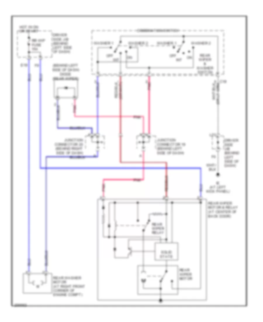
WIPER/WASHER
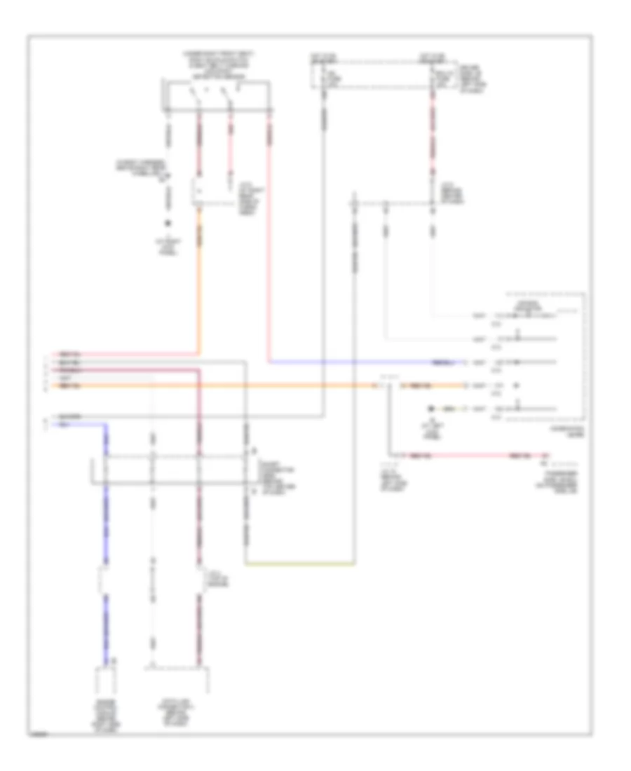
Front Wiper/Washer Wiring Diagram for Toyota RAV4 2005
List of elements for Front Wiper/Washer Wiring Diagram for Toyota RAV4 2005:
- (or pnk)
- C12
- C15
- C18
- Combi- nation meter
- Combination switch
- Driver side j/b (behind left side of dash)
- E22
- E25
- Ea (at front of right front fender)
- Front washer motor (at right front corner of engine compt)
- Front wiper motor (on left side of firewall)
- High
- Hot in on or start
- Ie (at left kick panel)
- Ig2 fuse 10a
- Int
- L10
- L21
- Low/ mist
- Off
- Solid state
- W/ drl
- Wash
- Washer ind
- Washer level warning switch
- Wip fuse 25a
- Wiper/ washer switch
Rear Wiper/Washer Wiring Diagram for Toyota RAV4 2005
List of elements for Rear Wiper/Washer Wiring Diagram for Toyota RAV4 2005:
- (behind left side of dash) diode (rear wiper)
- C18
- Combination switch
- Driver side j/b (behind left side of dash)
- E19
- Hot in on or start
- Ie (at left kick panel)
- Int
- Junction connector 19 (behind left side of dash)
- Junction connector 20 (behind right side of dash)
- L21
- Off
- Pnk
- Rear washer motor (at right front corner of engine compt)
- Rear wiper & washer switch
- Rear wiper motor
- Rear wiper motor & relay (at center of back door)
- Rear wiper relay
- Rr wip fuse 15a
- Solid state
- Washer 1
- Washer 2

 Čeština
 Dansk
Dansk Deutsch
 Ελληνικά
 English
 Español
 Suomi
Suomi Français
 Français
 עברית
עברית Hrvatski
 Magyar
 Italiano
 日本語
日本語 한국어
한국어 Nederlands
 Polski
 Português
 Português
 Română
 Русский
 Slovenčina
 Slovenščina
 Svenska
 Türkçe
 中文 (中国)