AIR CONDITIONING
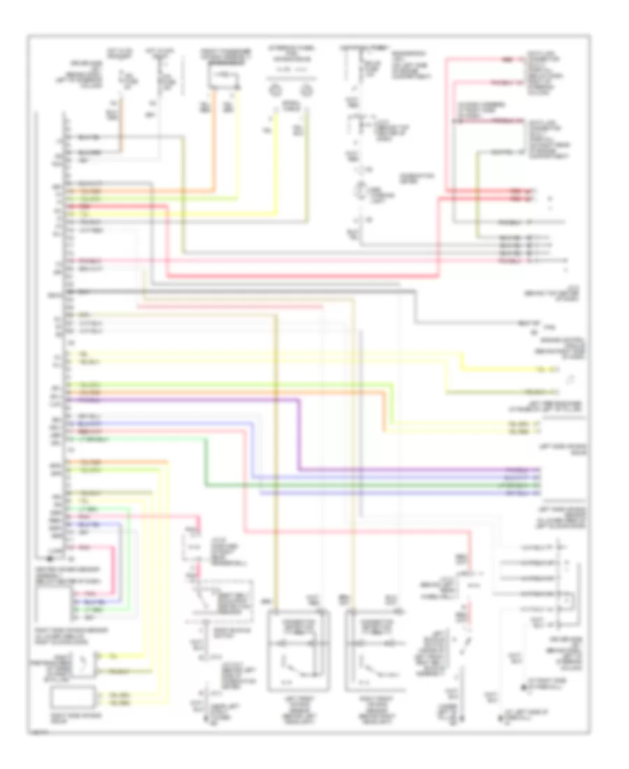
Automatic A/C Wiring Diagram, Rear A/C for Toyota Sienna CE 2003
 https://portal-diagnostov.com/license.html
Automotive Electricians Portal FZCO
Automotive Electricians Portal FZCO
https://portal-diagnostov.com/license.html
https://portal-diagnostov.com/license.html
Automotive Electricians Portal FZCO
Automotive Electricians Portal FZCO
List of elements for Automatic A/C Wiring Diagram, Rear A/C for Toyota Sienna CE 2003:
- (at front of right inner fender panel) ea
- (at left rear quarterpanel) bm
- (at right rear quarterpanel) bo
- (in dash harness, at right side of dash) i11
- (near left strut tower) ed
- A/c control assembly
- A23
- A24
- A25
- Auto
- Blower motor (rear cooling) (on rear cooling unit)
- Blower motor (rear heater) (on rear heater unit)
- Blower resistor transistor (cooler) (at right rear corner of vehicle)
- Blower resistor transistor (heater) (under right center seat)
- Blwc
- Blwh
- Blwr
- Bmc
- C20
- C21
- D20
- Dome fuse 10a
- Driver side j/b 1 (behind dash, left of steering column)
- Driver side r/b 5 (behind dash, left of steering column)
- Engine room j/b 2 (on left side of engine compartment)
- Front blower heater switch
- Fusible link block (on left side of engine compartment, inside engine room j/b 2)
- Gnd
- Heater fuse 10a
- Hot at all times
- Hot in on or start
- Hrc
- Hrh
- I11 (in dash harness, at right side of dash)
- Ig+
- Illum
- Interior lghts system
- J/b 3 (behind instrument cluster)
- J12
- Junction connector 17 (behind upper right side of dash)
- Junction connector 18 (on underside of steering column)
- Junction connector 23 (forward of right rear fenderwell)
- Junction connector 3 (behind left side of instrument cluster)
- Junction connector 6 (behind top center of dash)
- Junction connector 8 (behind top center of dash)
- Mhc
- Mhh
- Pnk
- R/b 7 (on left front of engine compartment)
- R/b 8 (on right rear of engine compt)
- Ra/c
- Rbat
- Rear a/c switch
- Rear heater intake air temperature sensor (under right center seat)
- Rear heater relay
- Red
- Rhi
- Rlo
- Rmi
- Rr a/c fuse 40a
- Rr clr fuse 40a
- Rr clr relay
- Rrat
- Rrhi
- Rrlo
- Rrme
- Rron
- Servo motor (on rear cooling unit)
- Tinh
- Tph
- Tset
- V10
- Vmc
- Vmh
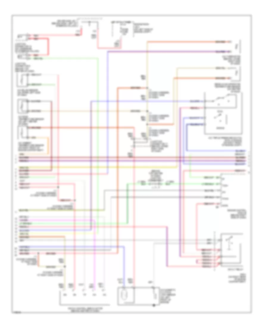
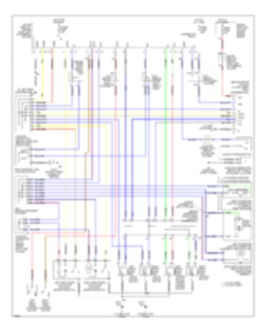
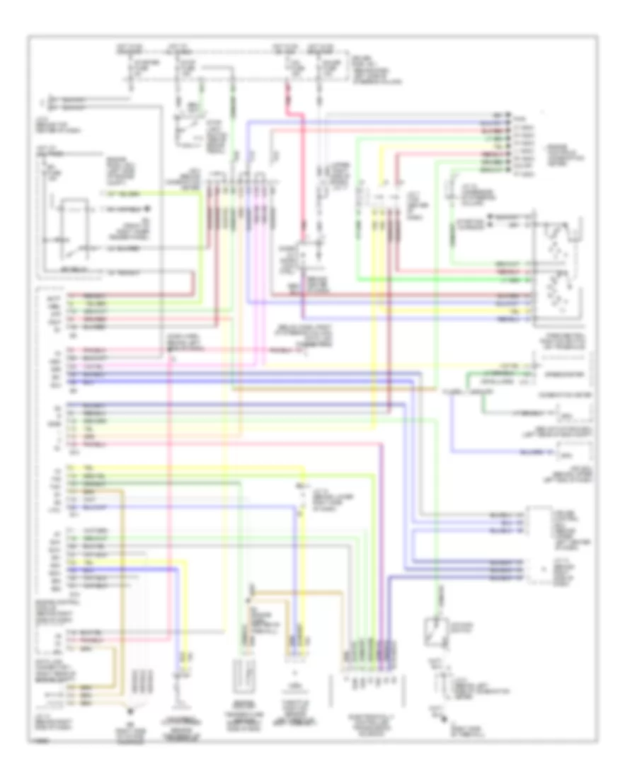
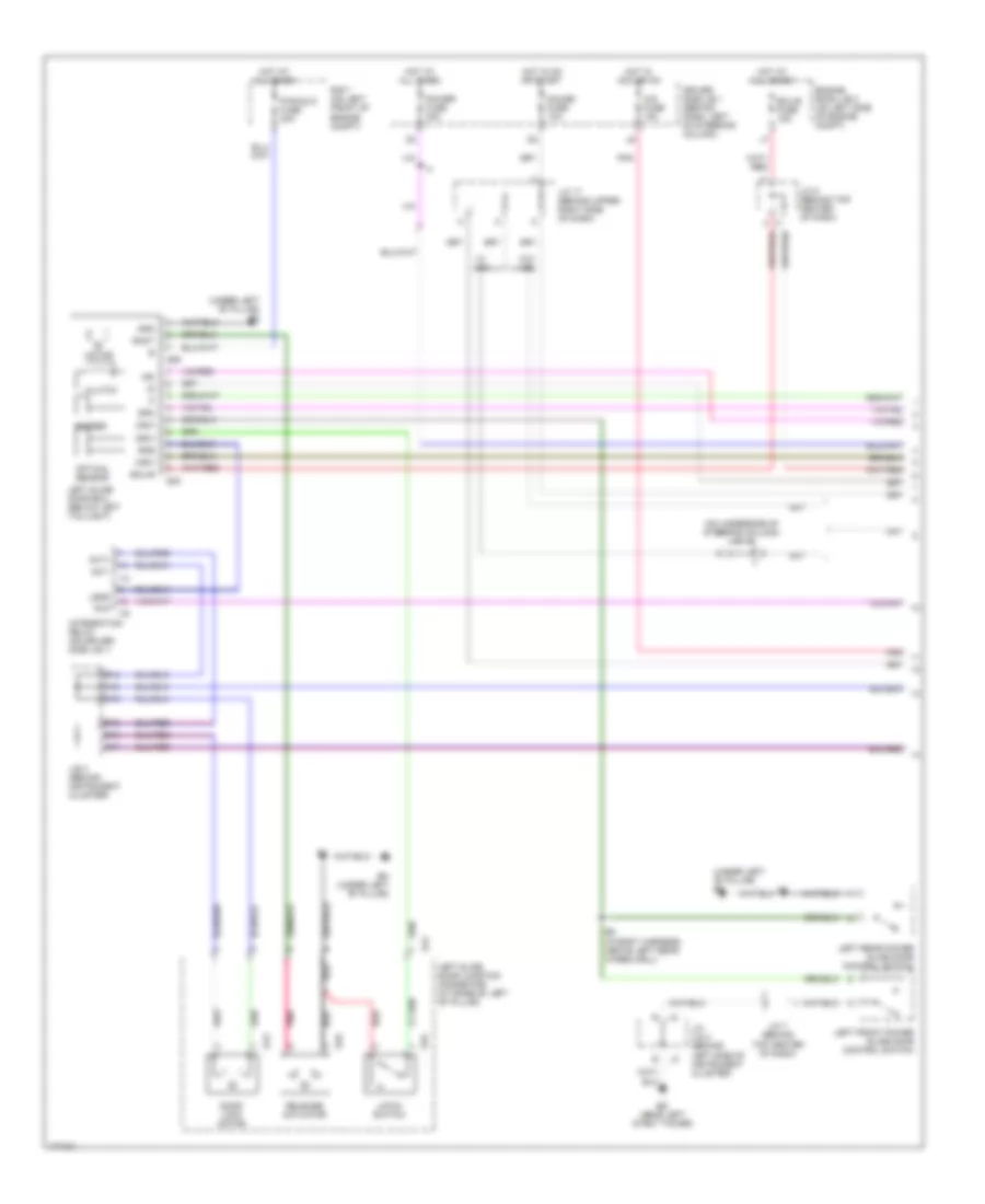
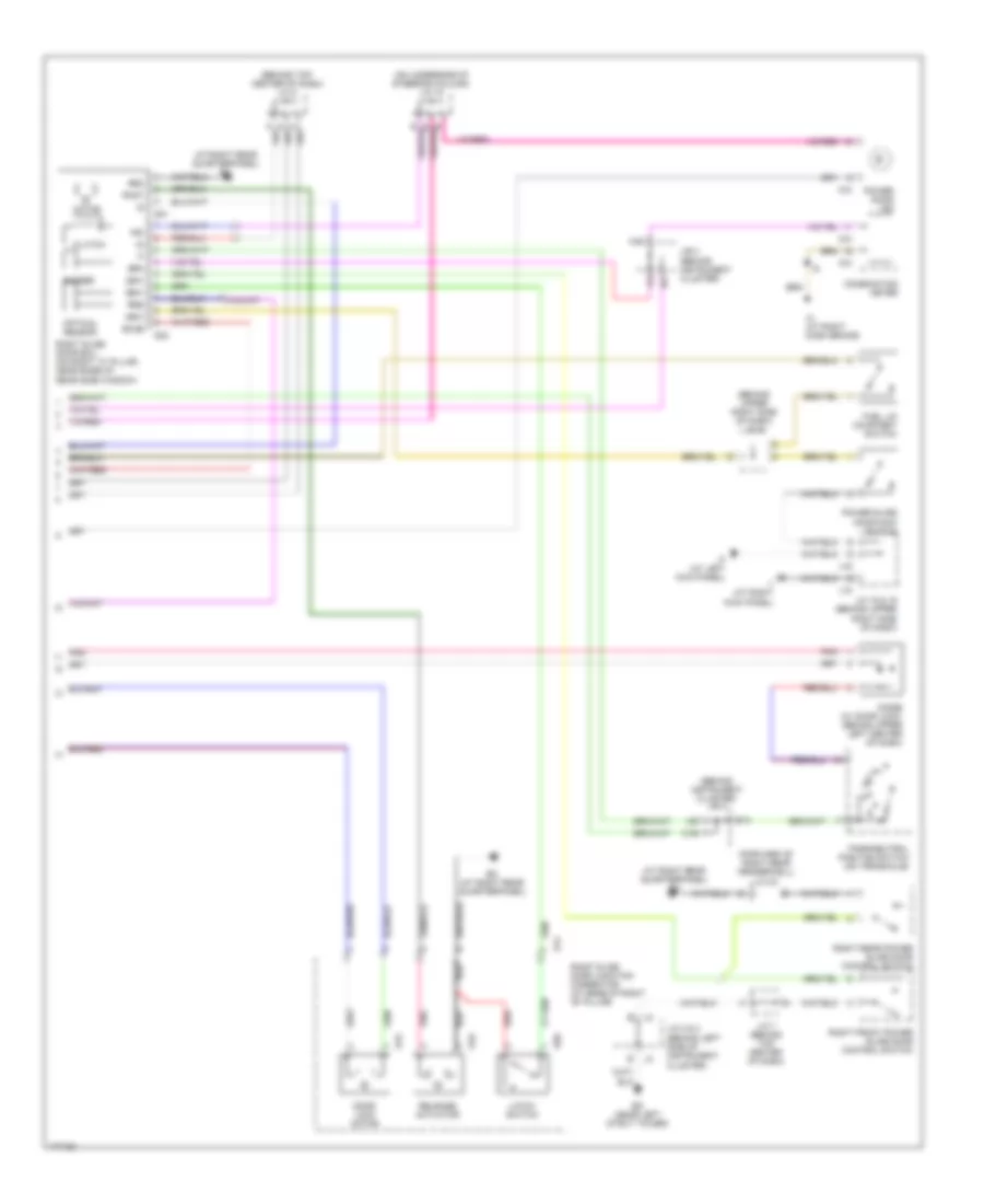
Automatic A/C Wiring Diagram, with Towing Package (1 of 3) for Toyota Sienna CE 2003
List of elements for Automatic A/C Wiring Diagram, with Towing Package (1 of 3) for Toyota Sienna CE 2003:
- (at right side of firewall) ij
- (near left strut tower) ed
- A/c control assembly
- A23
- A24
- A25
- Ac1
- Acon
- Aif
- Air
- Air inlet control servo motor (behind upper right side of dash)
- Air vent mode control servo motor (behind left center of dash)
- Alt fuse 140a
- Auto
- B/l
- Blower motor (behind right side of dash)
- Blw
- Blwc
- Blwh
- C20
- D20
- D21
- Def
- Defogger system
- Driver side j/b 1 (behind dash, left of steering column)
- Face
- Fdef
- Foot
- Front blower motor controller
- Front heater blower switch
- Front heater relay
- Fusible link block (on left side of engine compartment, inside engine room j/b 2)
- Gnd
- Heater fuse 10a
- Hot at all times
- Hot in on or start
- Hrc
- Hrh
- Htr fuse 50a
- I2 (in dash harness, at right side of dash)
- Ig+
- Illum
- Instrument cluster system
- Interior lights system
- J/b 3 (behind instrument cluster)
- Junction connector 17 (behind upper right side of dash)
- Junction connector 2 (behind left side of instrument cluster)
- Junction connector 8 (behind top center of dash)
- Lock
- Mfrs
- Mhc
- Mhh
- Mrs
- Passenger side r/b 4 (at right kick panel)
- Pnk
- Psw
- Rbat
- Rear a/c circuit
- Red
- Rrat
- Rrhi
- Rrlo
- Rrme
- Rron
- Spd
- Taco
- Tam
- Tinh
- Tpd
- Tph
- Tpi
- Tset
- Vmc
- Vmh
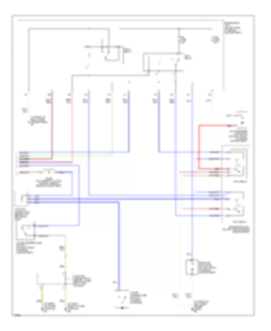
Automatic A/C Wiring Diagram, with Towing Package (2 of 3) for Toyota Sienna CE 2003
List of elements for Automatic A/C Wiring Diagram, with Towing Package (2 of 3) for Toyota Sienna CE 2003:
- (behind top center of dash) junction connector 7
- A/c
- A/c ambient temperature sensor (on right front of engine compartment)
- A/c magnetic clutch & lock sensor (on left front of engine)
- A/c room temperature sensor (on left center of dash)
- A/c solar sensor (on upper left side of dash)
- A/c thermistor (behind lower right side of dash)
- A/c triple pressure switch (dual & single) (on right front of engine compt)
- Acmg
- Air mix control servo motor (behind center of dash)
- Dome fuse 10a
- Driver side j/b 1 (behind dash, left of steering column)
- Dual
- Engine control module (behind right side of dash)
- Engine room j/b 2 (on left side of engine compt)
- Hot at all times
- I11 (in dash harness, at right side of dash)
- J12
- Junction connector 17 (behind upper right side of dash)
- Junction connector 18 (on underside of steering column)
- Junction connector 6 (behind top center of dash)
- Mg clt relay
- Pnk
- R/b 8 (on right rear of engine compartment)
- Rear a/c evaporator temperature sensor (on center of roof)
- Red
- Single
- Tach
- Thwo
- V10
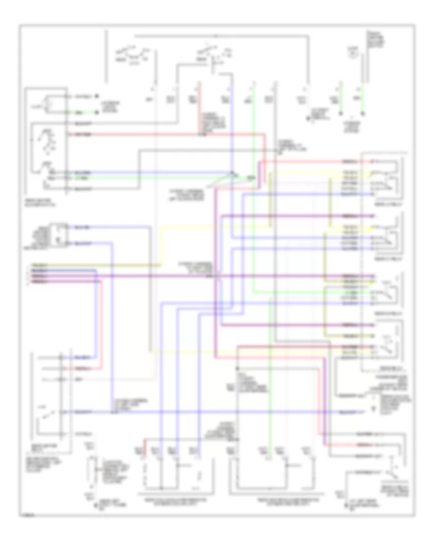
Automatic A/C Wiring Diagram, with Towing Package (3 of 3) for Toyota Sienna CE 2003
List of elements for Automatic A/C Wiring Diagram, with Towing Package (3 of 3) for Toyota Sienna CE 2003:
- (at front of left inner fender panel) ee
- (at front of right inner fender panel) ea
- (at rear of intake manifold)
- (at right side of intake manifold)
- A/c condenser fan motor (on right front of engine compartment)
- Cds fuse 30a
- Diode (a/c magnetic clutch) (on right rear of engine compartment)
- E3 (in engine harness, behind left headlight)
- Engine room j/b 2 (on left side of engine compartment)
- Engine room r/b 1 (on left side of engine compartment)
- Fan 1 relay
- Fan 2 relay
- Fan 3 relay
- I12 (in dash harness, at right side of dash)
- J13
- Junction connector 14 (behind lower right side of dash)
- Junction connector 8 (behind top center of dash)
- Main 1 relay
- Main 2 relay
- Pnk
- Radiator fan motor (on left front of engine compartment)
- Rdi fuse 30a
- Red
- Short pin
- Water temperature switch 1 (on right front of engine compartment)
- Water temperature switch 2 (on rear of engine)
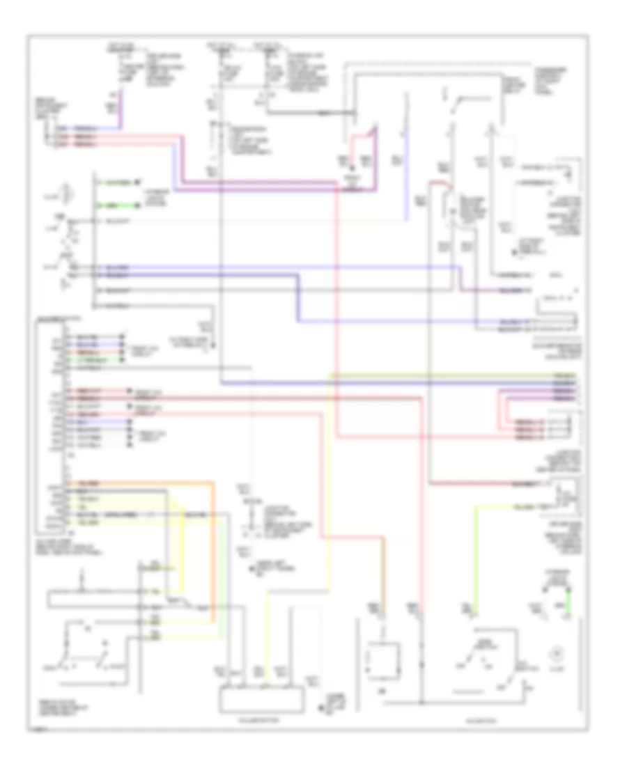
Automatic A/C Wiring Diagram, without Towing Package (1 of 3) for Toyota Sienna CE 2003
List of elements for Automatic A/C Wiring Diagram, without Towing Package (1 of 3) for Toyota Sienna CE 2003:
- (at right side of firewall) ij
- (near left strut tower) ed
- A/c control assembly
- A23
- A24
- A25
- Ac1
- Acon
- Aif
- Air
- Air inlet control servo motor (behind upper right side of dash)
- Air vent mode control servo motor (behind left center of dash)
- Alt fuse 140a
- Auto
- B/l
- Blower motor (behind right side of dash)
- Blw
- Blwc
- Blwh
- C20
- D20
- D21
- Def
- Defogger system
- Driver side j/b 1 (behind dash, left of steering column)
- Face
- Fdef
- Foot
- Front blower motor controller
- Front heater blower switch
- Front heater relay
- Fusible link block (on left side of engine compartment, inside engine room j/b 2)
- Gnd
- Heater fuse 10a
- Hot at all times
- Hot in on or start
- Hrc
- Hrh
- Htr fuse 50a
- I2 (in dash harness, at right side of dash)
- Ig+
- Illum
- Instrument cluster system
- Interior lights system
- J/b 3 (behind instrument cluster)
- Junction connector 17 (behind upper right side of dash)
- Junction connector 2 (behind left side of instrument cluster)
- Junction connector 8 (behind top center of dash)
- Lock
- Mfrs
- Mhc
- Mhh
- Mrs
- Passenger side r/b 4 (at right kick panel)
- Pnk
- Psw
- Rbat
- Rear a/c circuit
- Red
- Rrat
- Rrhi
- Rrlo
- Rrme
- Rron
- Spd
- Taco
- Tam
- Tinh
- Tpd
- Tph
- Tpi
- Tset
- Vmc
- Vmh
Automatic A/C Wiring Diagram, without Towing Package (2 of 3) for Toyota Sienna CE 2003
List of elements for Automatic A/C Wiring Diagram, without Towing Package (2 of 3) for Toyota Sienna CE 2003:
- (behind top center of dash) junction connector 7
- A/c
- A/c ambient temperature sensor (on right front of engine compartment)
- A/c magnetic clutch & lock sensor (on left front of engine)
- A/c room temperature sensor (on left center of dash)
- A/c solar sensor (on upper left side of dash)
- A/c thermistor (behind lower right side of dash)
- A/c triple pressure switch (dual & single) (on right front of engine compt)
- Acmg
- Air mix control servo motor (behind center of dash)
- Dome fuse 10a
- Driver side j/b 1 (behind dash, left of steering column)
- Dual
- Engine control module (behind right side of dash)
- Engine room j/b 2 (on left side of engine compt)
- Hot at all times
- I11 (in dash harness, at right side of dash)
- J12
- Junction connector 17 (behind upper right side of dash)
- Junction connector 18 (on underside of steering column)
- Junction connector 6 (behind top center of dash)
- Mg clt relay
- R/b 8 (on right rear of engine compartment)
- Rear a/c evaporator temperature sensor (on center of roof)
- Red
- Single
- Tach
- Thwo
- V10
Automatic A/C Wiring Diagram, without Towing Package (3 of 3) for Toyota Sienna CE 2003
List of elements for Automatic A/C Wiring Diagram, without Towing Package (3 of 3) for Toyota Sienna CE 2003:
- (at front of left inner fender panel) ee
- (at front of right inner fender panel) ea
- (at rear of intake manifold)
- (at right side of intake manifold)
- A/c condenser fan motor (on right front of engine compartment)
- Cds fuse 30a
- Diode (a/c magnetic clutch) (on right rear of engine compartment)
- Engine room j/b 2 (on left side of engine compartment)
- Engine room r/b 1 (on left side of engine compartment)
- Fan 1 relay
- Fan 2 relay
- Fan 3 relay
- J13
- Junction connector 14 (behind lower right side of dash)
- Junction connector 8 (behind top center of dash)
- Main 1 relay
- Radiator fan motor (on left front of engine compartment)
- Rdi fuse 30a
- Red
- Water temperature switch 1 (on right front of engine compartment)
- Water temperature switch 2 (on rear of engine)
Manual A/C Wiring Diagram, Rear A/C (1 of 2) for Toyota Sienna CE 2003
List of elements for Manual A/C Wiring Diagram, Rear A/C (1 of 2) for Toyota Sienna CE 2003:
- (at right side of firewall) ij
- (behind instrument cluster) j/b 3
- (near left strut tower) ed
- (under left "b" pillar) bk
- A/c amplifier (behind right side of dash, above kick panel)
- A/c fuse 5a
- A/c switch
- A/mp
- Ac1
- Act
- Blower motor (on rear cooling unit)
- Blower resistor (on rear cooling unit)
- Blower switch
- C20
- Cool
- D21
- Driver side j/b 1 (behind dash, left of steering column)
- Driver side r/b 5 (behind dash, left side of steering column)
- Engine room j/b 2 (on left side of engine compartment)
- F-a/c
- F-te
- Fan
- Front a/c circuit
- Front heater relay
- Fusible link block (on left side of engine compartment, inside engine room j/b 2)
- Gnd
- Heater fuse 10a
- Hot
- Hot at all times
- Hot in on or start
- Htr fuse 50a
- Ign
- Illum
- Interior lights system
- Junction connector 2 & 3 (behind left side of instrument cluster)
- Junction connector 8 (behind top center of dash)
- Led
- Lock
- Mcool
- Mgc
- Mhot
- Mode switch
- Off
- Passenger side r/b 4 (at right kick panel)
- Prs
- R-hvr
- Rr a/c fuse 40a
- Servo motor (under center of center seat)
- Sg1
- Sg2
- Volume switch
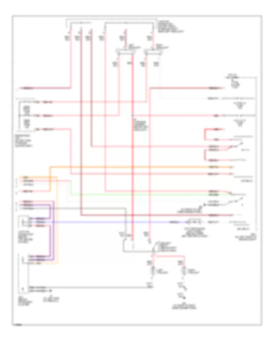
Manual A/C Wiring Diagram, Rear A/C (2 of 2) for Toyota Sienna CE 2003
List of elements for Manual A/C Wiring Diagram, Rear A/C (2 of 2) for Toyota Sienna CE 2003:
- (at left rear quarterpanel) bm
- (at right side of firewall) ij
- (in body harness, at left "b" pillar) b3
- (in body harness, at right rear quarterpanel) b13
- (in body harness, at right side of tailgate) b12
- (in body harness, in roof above left sliding door)
- (in body harness, in roof above left sliding door) b2
- (in dash harness, at left side of dash) i5
- (near left strut tower) ed
- B13 (in body harness, at right rear quarterpanel)
- Driver side r/b 5 (behind dash, left of steering column)
- Front heater blower switch
- Illum
- Interior lights system
- Junction connector 3 (behind left side of instrument cluster)
- Off
- Passenger side r/b 3 (on right rear corner of vehicle)
- Rear
- Rear cooling blower motor (on rear cooling unit)
- Rear cooling blower resistor (on rear cooling unit)
- Rear heater blower motor (on rear heater unit)
- Rear heater blower resistor (on rear heater unit)
- Rear heater blower switch
- Rear heater relay
- Rear hi relay (on right rear of vehicle)
- Rear lo relay
- Rear m1 relay
- Rear m2 relay
- Rear relay
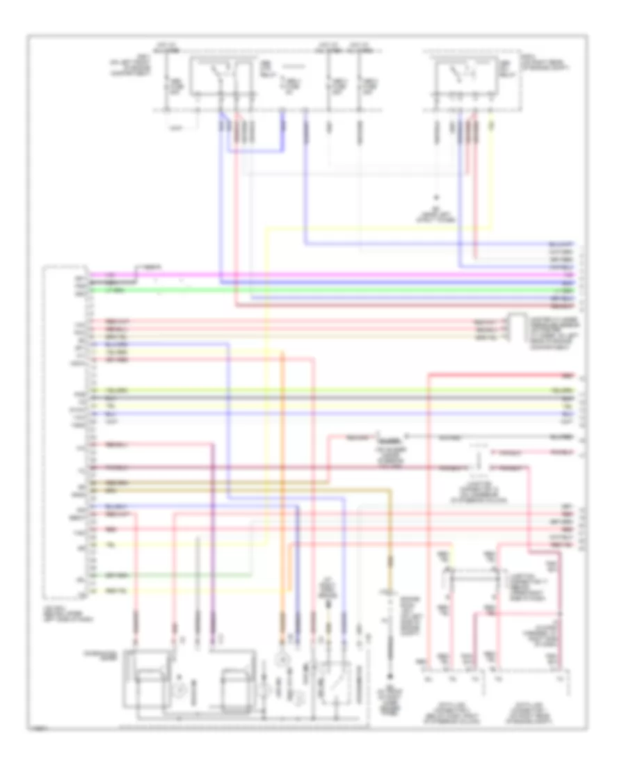
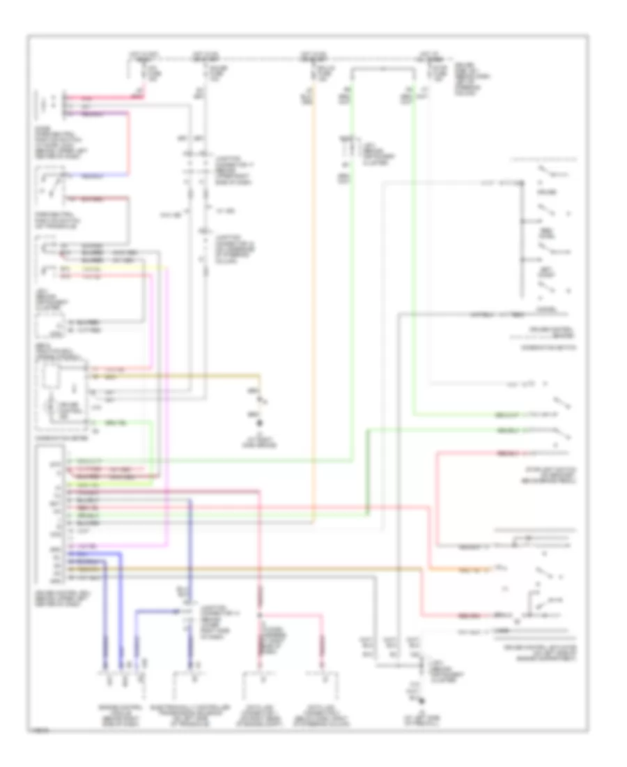
Manual A/C Wiring Diagram, with Towing Package (1 of 2) for Toyota Sienna CE 2003
List of elements for Manual A/C Wiring Diagram, with Towing Package (1 of 2) for Toyota Sienna CE 2003:
- (at right side of firewall) ij
- A/c
- A/c amplifier (behind right side of dash, above kick panel)
- A/c fuse 5a
- A/c magnetic clutch & lock sensor (on left front of engine)
- A/c switch
- A/c thermistor (behind lower right side of dash)
- A/c triple pressure switch (dual & single) (on right front of engine compt)
- Ac1
- Acmg
- Act
- Air inlet control servo motor (behind upper right side of dash)
- Air inlet control switch (rear window defogger switch)
- Alt fuse 140a
- Blower motor (behind right side of dash)
- Blower resistor (behind right side of dash, on blower housing)
- Blower switch
- C20
- D20
- D21
- Driver side j/b 1 (behind dash, left of steering column)
- Driver side r/b 5 (behind dash, left of steering column)
- Dual
- Engine control module (behind right side of dash)
- F-a/c
- F-te
- Fan
- Front heater relay
- Fusible link block (on left side of engine compartment, inside engine room j/b 2)
- Gnd
- Heater fuse 10a
- Hot at all times
- Hot in on or start
- Htr fuse 50a
- Ign
- Illum
- Interior lights system
- J/b 3 (behind instrument cluster)
- Junction connector 17 (behind upper right side of dash)
- Junction connector 2 & 3 (behind left side of instrument cluster)
- Junction connector 7 (behind top center of dash)
- Junction connector 8 (behind top center of dash)
- Led
- Lock
- Mgc
- Mode switch
- Off
- Passenger side r/b 4 (at right kick panel)
- Pnk
- Prs
- Sg1
- Single
- Tach
Manual A/C Wiring Diagram, with Towing Package (2 of 2) for Toyota Sienna CE 2003
List of elements for Manual A/C Wiring Diagram, with Towing Package (2 of 2) for Toyota Sienna CE 2003:
- (at front of left inner fender panel) ee
- (at front of right inner fender panel) ea
- (at rear of intake manifold)
- (at right side of intake manifold)
- (near left strut tower) ed
- A/c condenser fan motor (on right front of engine compartment)
- Cds fuse 40a
- E3 (in engine harness, behind left headlight)
- Engine room j/b 2 (on left side of engine compartment)
- Engine room r/b 1 (on left side of engine compartment)
- Fan 1 relay
- Fan 2 relay
- Fan 3 relay
- I12 (in dash harness, at right side of dash)
- J13
- Junction connector 14 (behind lower right side of dash)
- Junction connector 2 & 3 (behind left side of instrument cluster)
- Main 1 relay
- Main 2 relay
- Pnk
- Radiator fan motor (on left front of engine compartment)
- Rdi fuse 40a
- Red
- Short pin
- Water temperature switch 1 (on right front of engine compartment)
- Water temperature switch 2 (on rear of engine)
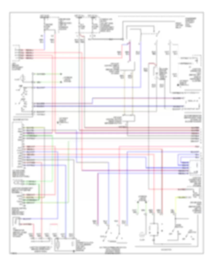
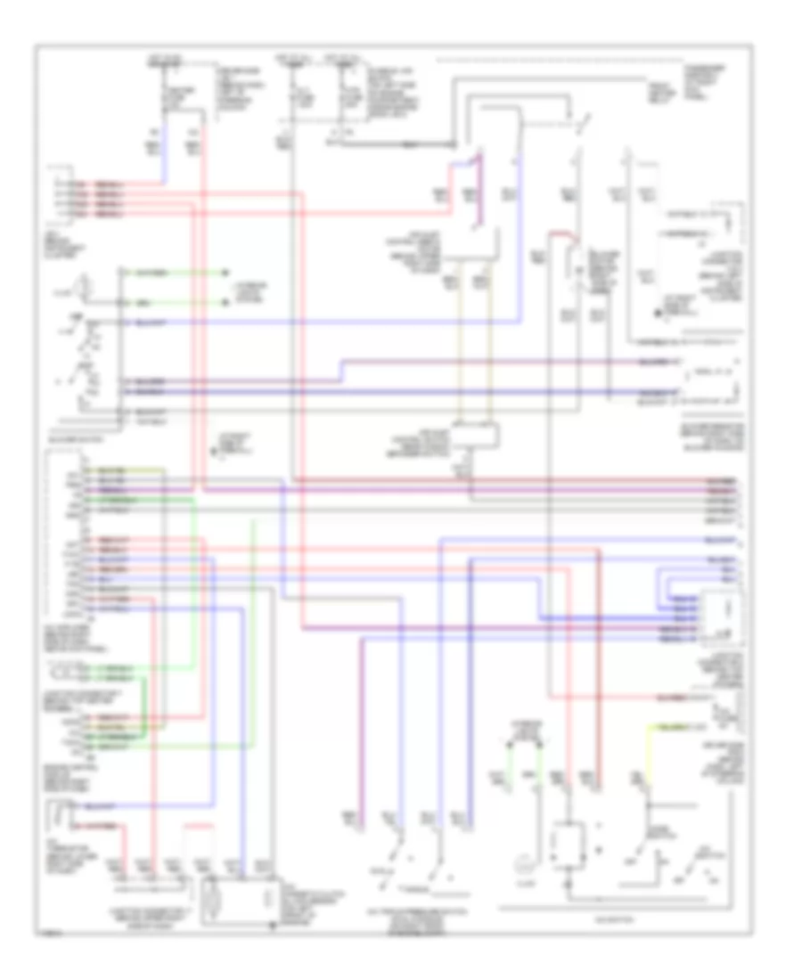
Manual A/C Wiring Diagram, without Towing Package (1 of 2) for Toyota Sienna CE 2003
List of elements for Manual A/C Wiring Diagram, without Towing Package (1 of 2) for Toyota Sienna CE 2003:
- (at right side of firewall) ij
- A/c
- A/c amplifier (behind right side of dash, above kick panel)
- A/c fuse 5a
- A/c magnetic clutch & lock sensor (on left front of engine)
- A/c switch
- A/c thermistor (behind lower right side of dash)
- A/c triple pressure switch (dual & single) (on right front of engine compt)
- Ac1
- Acmg
- Act
- Air inlet control servo motor (behind upper right side of dash)
- Air inlet control switch (rear window defogger switch)
- Alt fuse 140a
- Blower motor (behind right side of dash)
- Blower resistor (behind right side of dash, on blower housing)
- Blower switch
- C20
- D20
- D21
- Driver side j/b 1 (behind dash, left of steering column)
- Driver side r/b 5 (behind dash, left of steering column)
- Dual
- Engine control module (behind right side of dash)
- F-a/c
- F-te
- Fan
- Front heater relay
- Fusible link block (on left side of engine compartment, inside engine room j/b 2)
- Gnd
- Heater fuse 10a
- Hot at all times
- Hot in on or start
- Htr fuse 50a
- Ign
- Illum
- Interior lights system
- J/b 3 (behind instrument cluster)
- Junction connector 17 (behind upper right side of dash)
- Junction connector 2 & 3 (behind left side of instrument cluster)
- Junction connector 7 (behind top center of dash)
- Junction connector 8 (behind top center of dash)
- Led
- Lock
- Mgc
- Mode switch
- Off
- Passenger side r/b 4 (at right kick panel)
- Prs
- Sg1
- Single
- Tach
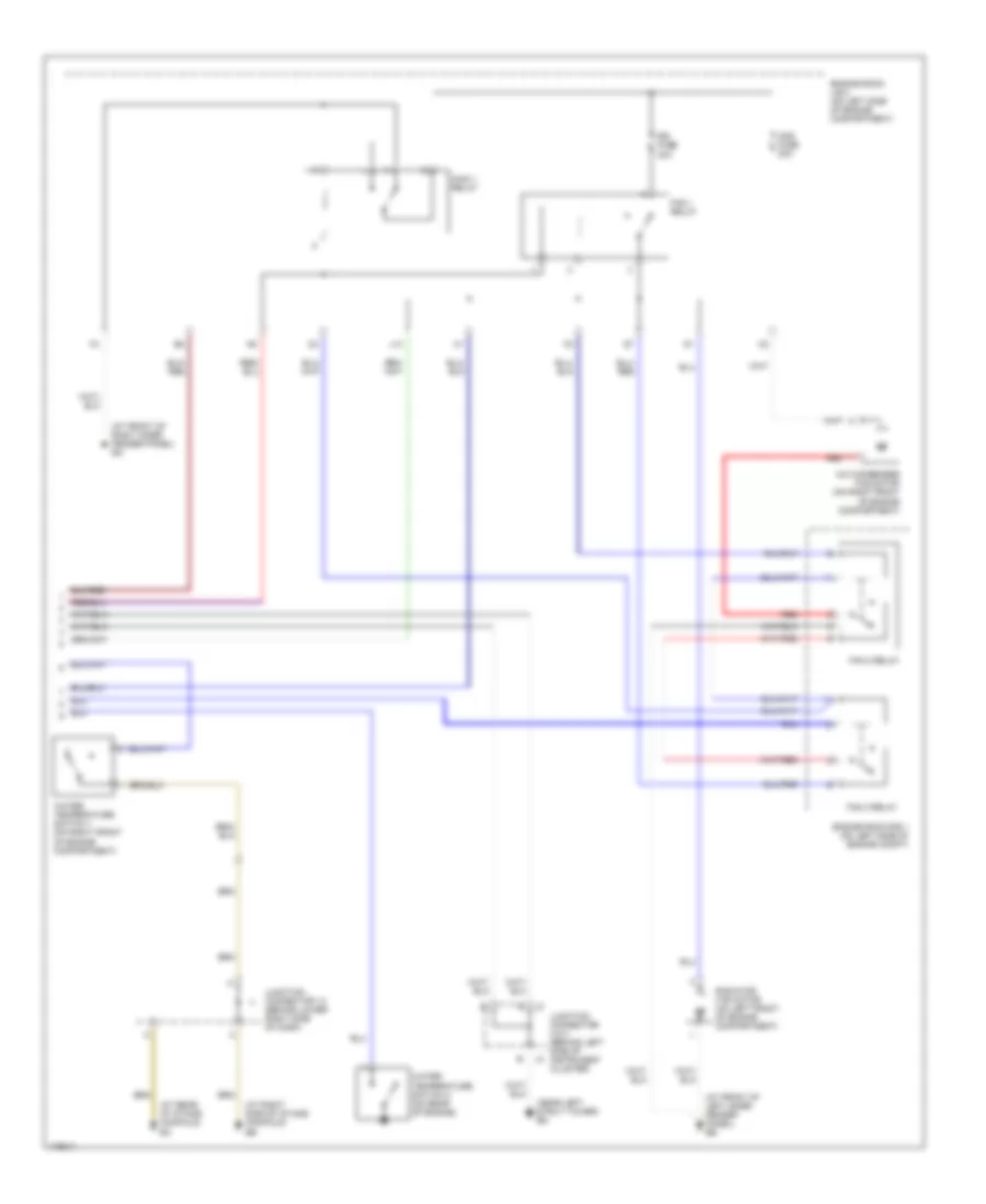
Manual A/C Wiring Diagram, without Towing Package (2 of 2) for Toyota Sienna CE 2003
List of elements for Manual A/C Wiring Diagram, without Towing Package (2 of 2) for Toyota Sienna CE 2003:
- (at front of left inner fender panel) ee
- (at front of right inner fender panel) ea
- (at rear of intake manifold)
- (at right side of intake manifold)
- (near left strut tower) ed
- A/c condenser fan motor (on right front of engine compartment)
- Cds fuse 30a
- Engine room j/b 2 (on left side of engine compartment)
- Engine room r/b 1 (on left side of engine compt)
- Fan 1 relay
- Fan 2 relay
- Fan 3 relay
- J13
- Junction connector 14 (behind lower right side of dash)
- Junction connector 2 & 3 (behind left side of instrument cluster)
- Main 1 relay
- Radiator fan motor (on left front of engine compartment)
- Rdi fuse 30a
- Red
- Water temperature switch 1 (on right front of engine compartment)
- Water temperature switch 2 (on rear of engine)
ANTI-LOCK BRAKES
Anti-lock Brakes Wiring Diagram, with VSC (1 of 3) for Toyota Sienna CE 2003
List of elements for Anti-lock Brakes Wiring Diagram, with VSC (1 of 3) for Toyota Sienna CE 2003:
- (at right dash brace) ih
- Abs 2 fuse 25a
- Abs 3 fuse 25a
- Abs 4 fuse 5a
- Abs fuse 60a
- Abs ind
- Abs mtr relay
- Abs sol relay
- Brake ind
- Buzzer
- C10
- C11
- Combination meter
- Data link connector 1 (on right rear of engine compt)
- Data link connector 3 (below dash, right of steering column)
- Ea (at front of right inner fender panel)
- Ebdw
- Ed (near left strut tower)
- Engine room j/b 2 (on left side of engine compt)
- Fss
- Gnd2
- Gyaw
- Hot at all times
- I2 (in dash harness, at right side of dash)
- Ind
- J10
- Junction connector 17 (behind upper right side of dash)
- Junction connector 18 (on underside of steering column)
- Lbl
- Master cylinder pressure sensor (on master cylinder, on left rear of engine compartment)
- Nca
- Pkb
- Pmc
- R/b 7 (on left front of engine compartment)
- R/b 8 (on right rear of engine compt)
- Red
- Sil
- Slip ind
- Sp1
- Speedometer
- Ss1
- Ss2
- Trac off ind
- Vcm
- Vsc buzzer (inside steering column)
- Vsc ecu (behind upper left side of dash)
- Vsc ind
- Vscw
- Yaw
- Ygnd
- Yiga
Anti-lock Brakes Wiring Diagram, with VSC (2 of 3) for Toyota Sienna CE 2003
List of elements for Anti-lock Brakes Wiring Diagram, with VSC (2 of 3) for Toyota Sienna CE 2003:
- (at right side of firewall) ij
- (behind instrument cluster) j/b 3
- (in dash harness, at right side of dash)
- (near left strut tower) ed
- A/t indicator light switch (park/neutral position switch) (on transaxle)
- A11
- A17
- A18
- B13
- B17
- B18
- Brake fluid level warning switch (on brake fluid reservoir)
- Brl
- Ccs
- Cig fuse 15a
- Cruise control ecu (behind upper left center of dash)
- D13
- Diode (park/neutral
- Driver side j/b 1 (behind dash, left of steering column)
- Ecu-ig fuse 15a
- Eng+
- Eng-
- Engine control module (behind right side of dash)
- Ess
- Gauge fuse 10a
- Gnd
- Hot at all times
- Hot in on or acc
- Hot in on or start
- Ig1
- J/b 3 (behind instrument cluster)
- Junction connector 17 (behind upper right side of dash)
- Junction connector 18 (on underside of steering column)
- Junction connectors 2 & 3 (behind left side of instrument cluster)
- Lbl
- Lvl2
- Nca
- Neo
- Pkb
- Pkb2
- Pnk
- Position switch) (w/ door lock control) (behind upper left center of dash)
- Red
- Rss
- Ss1
- Ss2
- Steering sensor (inside steering column)
- Stop fuse 15a
- Stoplight switch (on bracket, above brake pedal)
- Translate ecu (behind upper left side of dash)
- Trc+
- Trc-
- Vsc+
- Vsc-
Anti-lock Brakes Wiring Diagram, with VSC (3 of 3) for Toyota Sienna CE 2003
List of elements for Anti-lock Brakes Wiring Diagram, with VSC (3 of 3) for Toyota Sienna CE 2003:
- (at left side of firewall) ig
- (in body harness, in left quarter- panel)
- (in dash harness, at right side of dash)
- Batt
- Csw
- D/g
- Ed (near left strut tower)
- Fl+
- Fl-
- Fr+
- Fr-
- Gl1
- Gnd1
- Gnda
- Gyw2
- Ig1
- Iga
- J/b 3 (behind instrument cluster)
- Junction connector 6 (behind top center of dash)
- Left front abs speed sensor (mounted on hub assembly of left front wheel)
- Left rear abs speed sensor (mounted on hub assembly of left rear wheel)
- Nca
- Parking brake switch (on parking brake lever)
- Pnk
- Red
- Right front abs speed sensor (mounted on hub assembly of right front wheel)
- Right rear abs speed sensor (mounted on hub assembly of right rear wheel)
- Rl+
- Rl-
- Rr+
- Rr-
- Sflh
- Sflr
- Sfrh
- Sfrr
- Smc1
- Smc2
- Src1
- Src2
- Srlh
- Srlr
- Srrh
- Srrr
- Stp
- Trac off switch
- Vsc actuator (on left rear of engine compartment)
- Vsc ecu (behind upper left side of dash)
- Yaw rate sensor (between front seats, under carpet)
- Yaw2
Anti-lock Brakes Wiring Diagram, without VSC for Toyota Sienna CE 2003
List of elements for Anti-lock Brakes Wiring Diagram, without VSC for Toyota Sienna CE 2003:
- (at left side of firewall) ig
- (in body harness, in left quarter- panel)
- +bm
- +bs
- A11
- Abs actuator & ecu (on left rear of engine compt)
- Abs fuse 60a
- Abs warning ind
- B j3
- B13
- B17
- B18
- Brake ind
- Brl
- C10
- C11
- Cig fuse 15a
- Combination meter
- D/g
- Data link connector 1 (on right rear of engine compt)
- Data link connector 3 (below dash, right of steering column)
- Diode (park/neutral position switch) (w/ wireless door lock control) (behind upper left center of dash)
- Driver side j/b 1 (behind dash, left of steering column)
- Ea (at front of right inner fender panel)
- Ecu-ig fuse 15a
- Ed (near left strut tower)
- Ee (at front of left inner fender panel)
- Engine room j/b 2 (on left side of engine compt)
- Fl+
- Fl-
- Fr+
- Fr-
- Gauge fuse 10a
- Gnd1
- Gnd2
- Headlights system
- Hot at all times
- Hot in on or acc
- Hot in on or start
- I2 (in dash harness, at right side of dash)
- Ig1
- Ij (at right side of firewall)
- Init
- J/b 3 (behind instrument cluster)
- J10
- J2 b
- Junction connector 17 (behind upper right side of dash)
- Junction connector 6 (behind top center of dash)
- Junction connectors 2 & 3 (behind left side of instrument cluster)
- Left front abs speed sensor (mounted on hub assembly of left front wheel)
- Left rear abs speed sensor (mounted on hub assembly of left rear wheel)
- Nca
- Park/neutral position switch (on transaxle)
- Pkb
- Pnk
- R/b 7 (on left front of engine compt)
- Red
- Right front abs speed sensor (mounted on hub assembly of right front wheel)
- Right rear abs speed sensor (mounted on hub assembly of right rear wheel)
- Rl+
- Rl-
- Rr+
- Rr-
- Sil
- Speedo- meter
- Spo
- Stop fuse 15a
- Stoplight switch (on bracket, above brake pedal)
- Stp
- Tire pressure ind
- Tire pressure warning standardization switch (on left side of dash)
- W/ wireless door lock control
- W/o wireless door lock control
- Wtir
ANTI-THEFT
Forced Entry Wiring Diagram for Toyota Sienna CE 2003
List of elements for Forced Entry Wiring Diagram for Toyota Sienna CE 2003:
- +b1
- +b2
- A10
- B9 (in body harn, at top of left rear wheelwell)
- Back door courtesy switch
- Back door unlock detection switch
- Bk (under left "b" pillar)
- Bn (at right side of tailgate)
- Cty
- D18
- Dcty
- Dome fuse 10a
- Door fuse 25a
- Door locks system
- Driver side j/b 1 (behind dash, left of steering column)
- Dswd
- Dswh
- Dswl
- Dswp
- Ea (at front of right inner fender panel)
- Ecu-ig fuse 15a
- Engine control module
- Engine hood courtesy switch (on front of engine compt)
- Engine room j/b 2 (on left side of engine compt)
- Exterior lights system
- Head
- Headlights system
- Horn
- Horn fuse 10a
- Horns system
- Hot at all times
- Hot in on or start
- I11
- I16
- If (at left kick panel)
- Ii (at right kick panel)
- Ij (at right side of firewall)
- Imld
- Ind
- Integration relay
- J/b 3 (behind instrument cluster
- J/c 15 (behind upper right side of dash)
- J/c 18 (on under- side of steering column)
- J/c 2 & 3 (behind left side of instrument cluster)
- J/c 22 (on right rear corner of vehicle)
- J/c 4 (behind upper left side of dash)
- J/c 5 (behind upper right side of dash)
- J/c 9 (behind top center of dash)
- J12
- Ksw
- Left front door courtesy switch
- Left slide door courtesy switch
- Left slide door junction connector (unlock detection switch) (at base of left "b" pillar)
- Lswd
- Lswp
- Lswr
- Pani
- Pcty
- Red
- Right front door courtesy switch
- Right slide door courtesy switch
- Right slide door junction connector (unlock detection switch) (at base of right "b" pillar)
- S12
- S13
- S14
- S15
- Scty
- Sh-
- Tail
- Theft deterrent ecu (behind center of dash)
- Theft deterrent horn (on right rear of engine compt)
- Theft deterrent indicator light
- Ul2
- Ul3
- W/ power slide door
- W/o power slide door
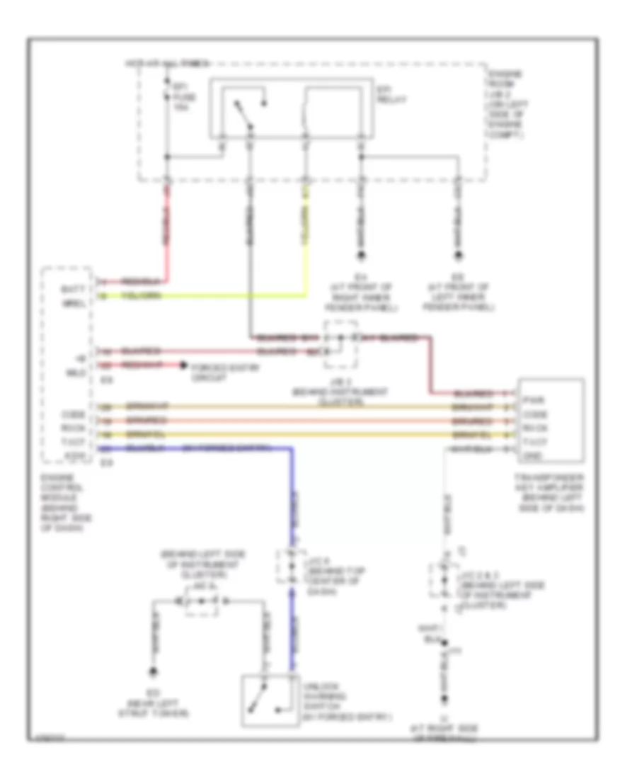
Immobilizer Wiring Diagram for Toyota Sienna CE 2003
List of elements for Immobilizer Wiring Diagram for Toyota Sienna CE 2003:
- (behind left side of instrument cluster) j/c 3
- (w/ forced entry)
- Batt
- Code
- Ea (at front of right inner fender panel)
- Ed (near left strut tower)
- Ee (at front of left inner fender panel)
- Efi fuse 15a
- Efi relay
- Engine control module (behind right side of dash)
- Engine room j/b 2 (on left side of engine compt)
- Forced entry circuit
- Gnd
- Hot at all times
- I11
- Ij (at right side of firewall)
- Imld
- J/b 3 (behind instrument cluster)
- J/c 2 & 3 (behind left side of instrument cluster)
- J/c 6 (behind top center of dash)
- Ksw
- Mrel
- Pwr
- Rxck
- Transponder key amplifier (behind left side of dash)
- Txct
- Unlock warning switch (w/ forced entry)
BODY CONTROL MODULES
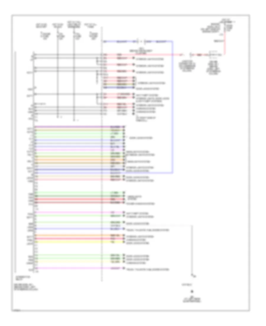
Body Control Modules Wiring Diagram, with Power Door Locks for Toyota Sienna CE 2003
List of elements for Body Control Modules Wiring Diagram, with Power Door Locks for Toyota Sienna CE 2003:
- Acc
- Act+
- Act-
- Actd
- Anti-theft system
- Auto
- Bcty
- Bm (at left rear quarterpanel)
- Bzr
- Cig fuse 15a
- Csb
- Cse
- Cso
- D19
- Dcty
- Dome fuse 10a
- Door fuse 25a
- Door locks system
- Dout
- Driver side j/b 1 (behind dash, left of steering column)
- Engine room j/b 2 (on left side of engine compt)
- Exterior lights system
- Gauge fuse 10a
- H11
- Headlights system
- Hot at all times
- Hot in on or acc
- Hot in on or start
- Hot w/ tail- light relay energized
- Hrly
- I13
- I16
- Ij (at right side of firewall)
- Integration relay
- Interior lights system
- Interior lights, door locks & anti-theft systems
- J/b 3 (behind instrument cluster)
- J12
- Junction connector 18 (on underside of steering column)
- Ksw
- Lsds
- Lswd
- Lswp
- P/w
- Pani
- Pcty
- Pkbl
- Pnk
- Power windows system
- Prg
- Rda
- Red
- S12
- Scty
- Sld
- Tail fuse 10a
- Trly
- Trunk, tailgate, fuel doors system
- Ul1
- Ul2
- Ul3
- V10
- V11
- Warning system
- Wrn
- Wrnp
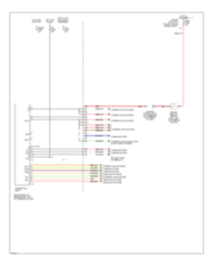
Body Control Modules Wiring Diagram, without Power Locks for Toyota Sienna CE 2003
List of elements for Body Control Modules Wiring Diagram, without Power Locks for Toyota Sienna CE 2003:
- Acc
- Cig fuse 15a
- Dcty
- Dome fuse 10a
- Driver side j/b 1 (behind dash, left of steering column)
- Engine room j/b 2 (on left side of engine compt)
- Exterior lights system
- Gauge fuse 10a
- H11
- Headlights system
- Hot at all times
- Hot in on or acc
- Hot in on or start
- Hot w/ tail- light relay energized
- Hrly
- I13
- Ij (at right side of firewall)
- Integration relay
- Interior lights system
- Interior lights, door locks & anti-theft systems
- J12
- Junction connector 18 (on underside of steering column)
- Ksw
- Pcty
- Pkbl
- Red
- S12
- Scty
- Tail fuse 10a
- Trly
- V10
- Warning system
- Wrn
- Wrnp
COMPUTER DATA LINES
Computer Data Lines Wiring Diagram for Toyota Sienna CE 2003
List of elements for Computer Data Lines Wiring Diagram for Toyota Sienna CE 2003:
- (at rear of intake manifold) ec
- (at right side of firewall) ij
- Abs actuator & ecu (on left rear of engine compt)
- B11
- Bat
- Center air bag sensor assembly (below center of dash)
- Combination meter
- Cruise control ecu (behind upper left center of dash)
- D/g
- Data link connector 1 (on right rear of engine compt)
- Data link connector 3 (below dash, right of steering column)
- Driver side j/b 1 (behind dash, left of steering column)
- E4 (in eng harness, at center of firewall)
- Efi fuse 15a
- Efi relay
- Engine control module (behind right side of dash)
- Engine room j/b 2 (on left side of engine compt)
- Hot at all times
- I11
- I2 (in dash harness, at right side of of dah)
- J/b 3 (behind instrument cluster)
- J/c 14 (behind lower right side of dash)
- J/c 17 (behind upper right side of dash)
- J/c 18 (w/ vsc) (on underside of steering column)
- J/c 2 & 3 (behind left side of instrument cluster)
- J/c 6 (behind top center of dash)
- J/c 8 (behind top center of dash)
- J10
- Obd fuse 7.5a
- Red
- Red red
- Sil
- Translate ecu (w/ vsc) (behind upper left side of dash)
- Vsc ecu (behind upper left side of dash)
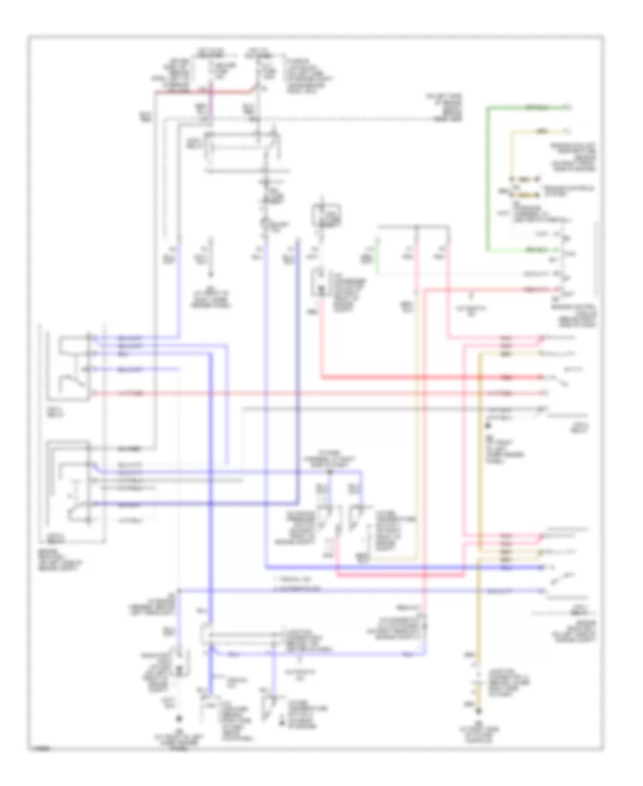
COOLING FAN
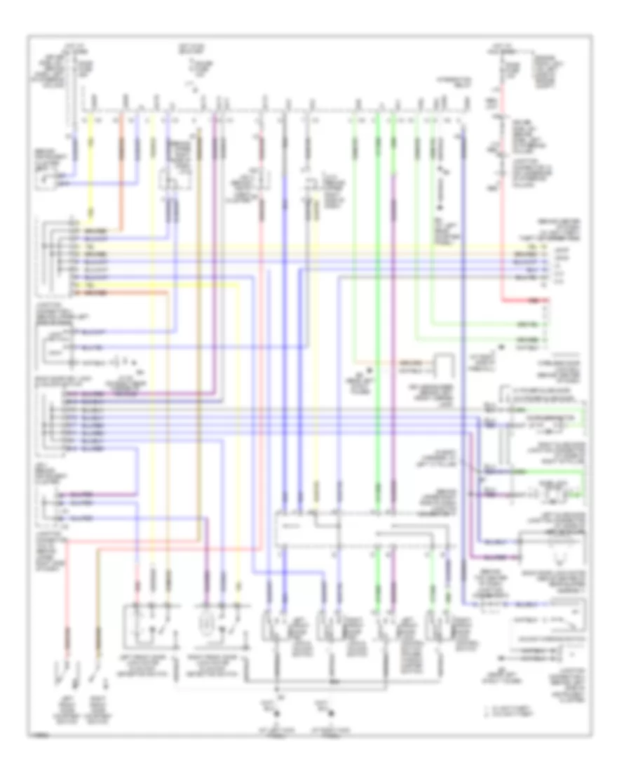
Cooling Fan Wiring Diagram, with Towing Package for Toyota Sienna CE 2003
List of elements for Cooling Fan Wiring Diagram, with Towing Package for Toyota Sienna CE 2003:
- (in dash harness, at right side of dash) i12
- (on left side of engine compt) engine room j/b 2
- A/c amplifier (behind right side of dash, above kick panel)
- A/c condenser fan motor (on right front of engine compt)
- A/c magnetic clutch diode (on right rear of engine compt)
- A/c single pressure switch (on right front of engine compt)
- Act
- Alt fuse 140a
- Automatic a/c
- Cds fuse 40a
- Driver side j/b 1 (behind dash, left of steering column)
- E11
- E3 (in engine harness, behind left headlight)
- E4 (in engine harness, at center of firewall)
- Ea (at front of
- Eb (at right side of intake manifold)
- Ee (at front of left inner fender panel)
- Engine control module (behind right side of dash)
- Engine controls system
- Engine coolant temparature sensor (on right front side of engine)
- Engine room r/b 1 (on left side of engine compt)
- Fan
- Fan 1 relay
- Fan 2 relay
- Fan 3 relay
- Fusible link block (on left side of engine compt, inside engine room j/b 2)
- Heater fuse 10a
- Hot at all times
- Hot in on or start
- J13
- Junction connector 14 (behind lower right side of dash)
- Junction connector 8 (behind top center of dash)
- Main 1 relay
- Main 2 relay
- Manual a/c
- Pnk
- Radiator fan motor (on left front of engine compt)
- Rdi fuse 40a
- Red
- Right inner fender panel)
- Short pin
- Thw
- Water temperature switch 1 (on right front of engine compt)
- Water temperature switch 2 (on rear of engine)
Cooling Fan Wiring Diagram, without Towing Package for Toyota Sienna CE 2003
List of elements for Cooling Fan Wiring Diagram, without Towing Package for Toyota Sienna CE 2003:
- A/c amplifier (behind right side of dash, above kick panel)
- A/c condenser fan motor (on right front of engine compt)
- A/c magnetic clutch diode (on right rear of engine compt)
- A/c single pressure switch (on right front of engine compt)
- Act
- Alt fuse 140a
- Automatic a/c
- Cds fuse 30a
- Driver side j/b 1 (behind dash, left of steering column)
- E11
- E4 (in engine harness, at center of firewall)
- Ea (at front of right inner fender panel)
- Eb (at right side of intake manifold)
- Ee (at front of left inner fender panel)
- Engine control module (behind right side of dash)
- Engine controls system
- Engine coolant temparature sensor (on right front side of engine)
- Engine room j/b 2 (on left side of engine compt)
- Engine room r/b 1 (on left side of engine compt)
- Fan
- Fan 1 relay
- Fan 2 relay
- Fan 3 relay
- Fusible link block (on left side of engine compt, inside engine room j/b 2)
- Heater fuse 10a
- Hot at all times
- Hot in on or start
- J13
- Junction connector 14 (behind lower right side of dash)
- Junction connector 8 (behind top center of dash)
- Main 1 relay
- Manual a/c
- Radiator fan motor (on left front of engine compt)
- Rdi fuse 30a
- Red
- Thw
- Water temperature switch 1 (on right front of engine compt)
- Water temperature switch 2 (on rear of engine)
CRUISE CONTROL
Cruise Control Wiring Diagram for Toyota Sienna CE 2003
List of elements for Cruise Control Wiring Diagram for Toyota Sienna CE 2003:
- (w/ vsc)
- (w/o vsc)
- A13
- Abs & traction ecu (translate ecu)
- B10
- B14
- B18
- C10
- C22
- Cancel
- Ccs
- Cig fuse 15a
- Combination meter
- Combination switch
- Cruise
- Cruise control actuator (on left side of engine compartment)
- Cruise control ecu (behind upper left center of dash)
- Cruise control ind
- Cruise control switch
- D13
- Data link connector 1 (on right rear of engine compt)
- Data link connector 3 (below dash, right of steering column)
- Diode (park/neutral position switch) (w/ door lock) (behind upper left center of dash)
- Driver side j/b 1 (behind dash, left of steering column)
- E10
- Ecc
- Ect
- Ecu-ig fuse 15a
- Electronically controlled transmission solenoid (on left side of transaxle)
- Engine control module (behind right side of dash)
- Gauge fuse 10a
- Gnd
- Hot at all times
- Hot in acc or on
- Hot in on or start
- I2 (in dash harness, at right side of dash)
- Idl
- Idlo
- Ig (at left side of firewall)
- Ih (at right dash brace)
- J/b 3 (behind instrument cluster)
- Junction connector 13 (behind lower right side of dash)
- Junction connector 17 (behind upper right side of dash)
- Junction connector 18 (on underside of steering column)
- Od1
- Park/neutral position switch (on transaxle)
- Pnk
- Res/ accel
- Set/ coast
- Spd
- Stop fuse 15a
- Stoplight switch (on bracket, above brake pedal)
- Stp
- W/ vsc
- W/o vsc
DEFOGGERS
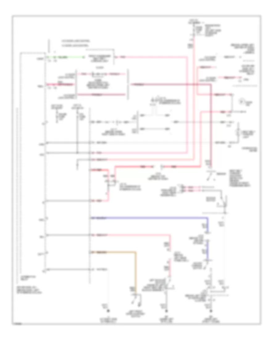
Defoggers Wiring Diagram for Toyota Sienna CE 2003
List of elements for Defoggers Wiring Diagram for Toyota Sienna CE 2003:
- A25
- C21
- Def fuse 30a
- Defogger relay
- Driver side j/b 1 (behind dash, left of steering column)
- Ed (near left strut tower)
- Heater fuse 10a
- Hot at all times
- Hot in on or start
- If (at left kick panel)
- Ii (at right kick panel)
- Interior lights system
- J/b 3 (behind instrument cluster)
- J/c 22 (on right rear corner of vehicle) bn (at right side of tailgate)
- J/c 7 (behind top center of dash)
- J12
- J13
- Left mirror heater (left remote control mirror)
- Mirror-heater fuse 10a
- R15
- R16
- Rear window defogger
- Rear window defogger switch (a/c control assembly) (automatic a/c)
- Rear window defogger switch (manual a/c)
- Right mirror heater (right remote control mirror)
- Solid state
ENGINE PERFORMANCE
3.0L
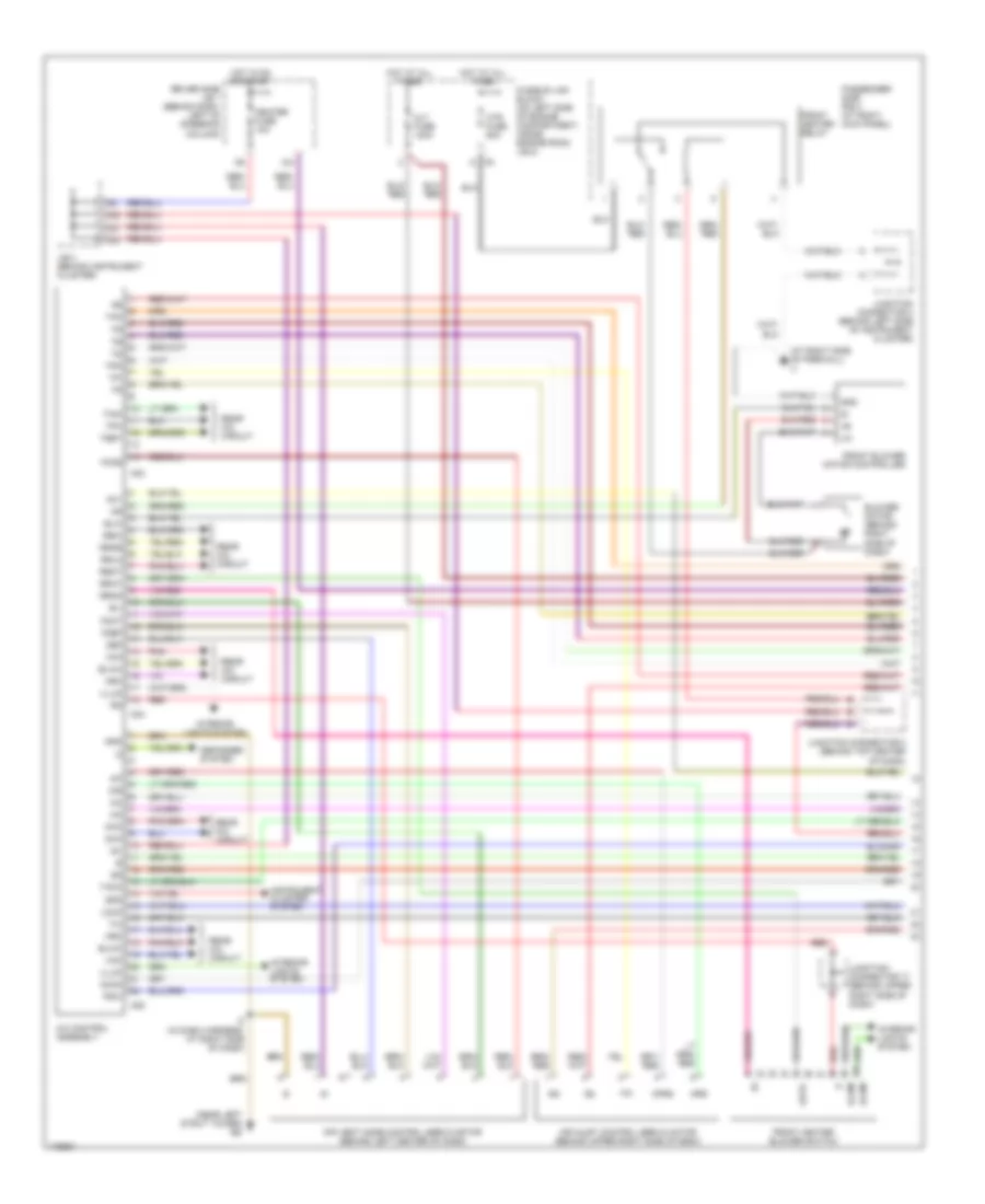
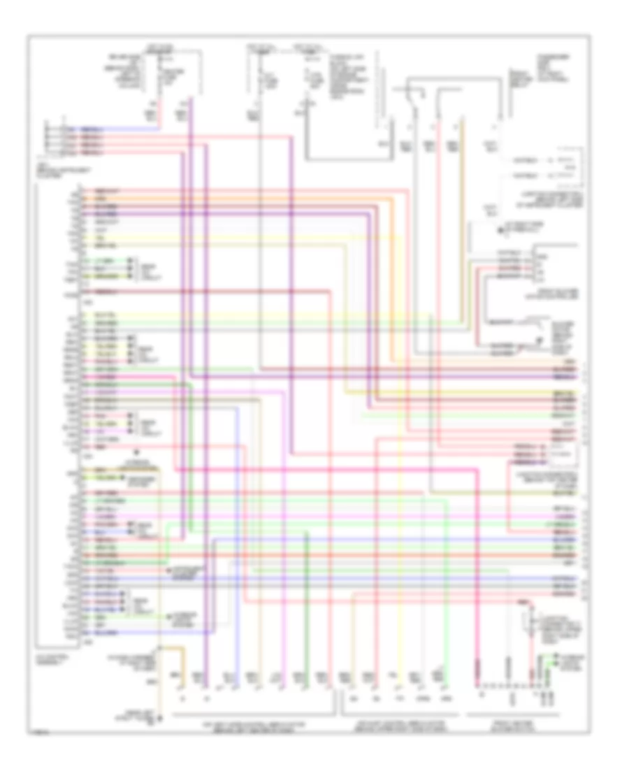
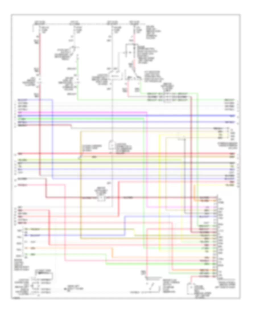
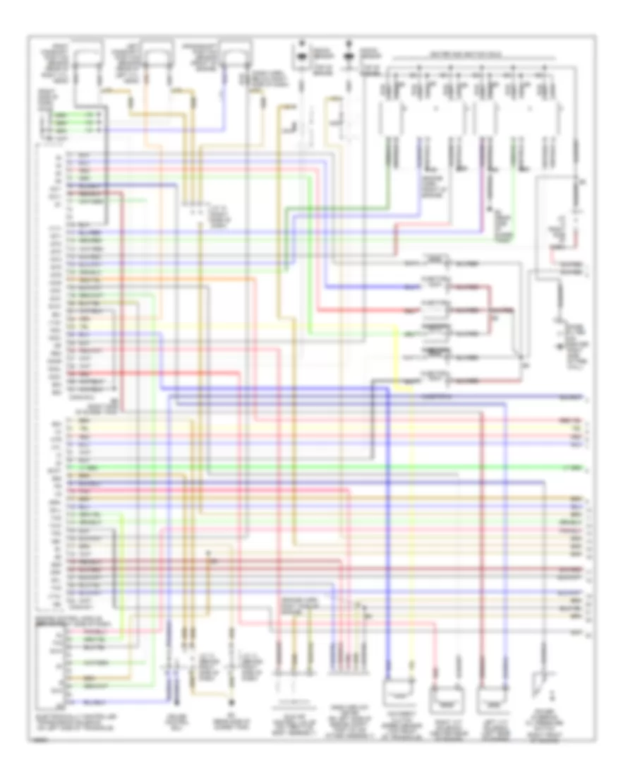
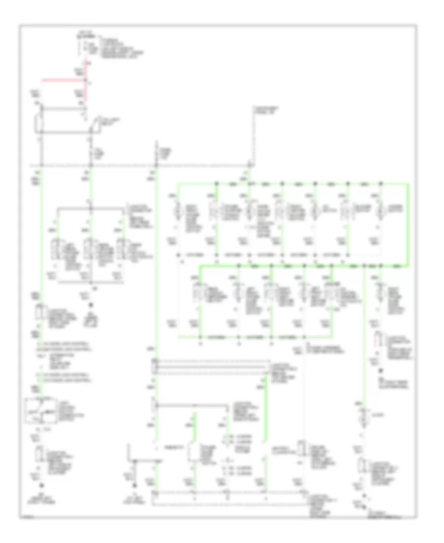
3.0L, Engine Performance Wiring Diagram (1 of 4) for Toyota Sienna CE 2003
List of elements for 3.0L, Engine Performance Wiring Diagram (1 of 4) for Toyota Sienna CE 2003:
- (engine harn, front of engine)
- (engine harn, right side of engine)
- (right side of dash)
- (right side of dash) j/c 12
- Acis
- Afl+
- Afl-
- Afr+
- Afr-
- Below right side of dash) i10
- Conn e11
- Conn e12
- Crankshaft position sensor (front of engine)
- Cruise control ecu
- E01
- E02
- E03
- E04
- E05
- E2g
- Eb (right side of surge tank)
- Ec (rear side of surge tank)
- Electronically controlled transmission solenoid (on left side of transaxle)
- Engine control module (behind right side of dash)
- Evp1
- Htl
- Htr
- I10
- Idle air control valve (on throttle body assembly)
- Igf
- Igniter and ignition coils
- Igt1
- Igt2
- Igt3
- Igt4
- Igt5
- Igt6
- Injector 1
- Injector 2
- Injector 3
- Injector 4
- Injector 5
- Injector 6
- J/c (right side of dash)
- J/c 12
- J/c 13 (behind right side of dash)
- J/c 14 (behind right side of dash)
- Knkl
- Knkr
- Knock sensor (top of engine)
- Left camshaft position sensor (rear of left cyl head)
- Left vvt solenoid (left rear of engine)
- Mass airflow meter (on left side of engine compt, part of air intake assembly)
- Nc2+
- Nc2-
- Nca
- Ne+
- Ne-
- Noise filter (on center right side of fire- wall)
- O/d direct clutch speed sensor (top front of transaxle)
- Oc1+
- Oc1-
- Oc2+
- Oc2-
- Pnk
- Power steering oil pressure switch (right front of engine)
- Red
- Right camshaft position sensor (rear of right cyl head)
- Right vvt solenoid (center rear of engine)
- Rso
- Sln+
- Sln-
- Tha
- Tho
- Thw
- Tpc
- Vta1
- Vv1+
- Vv2+
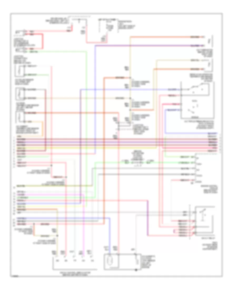
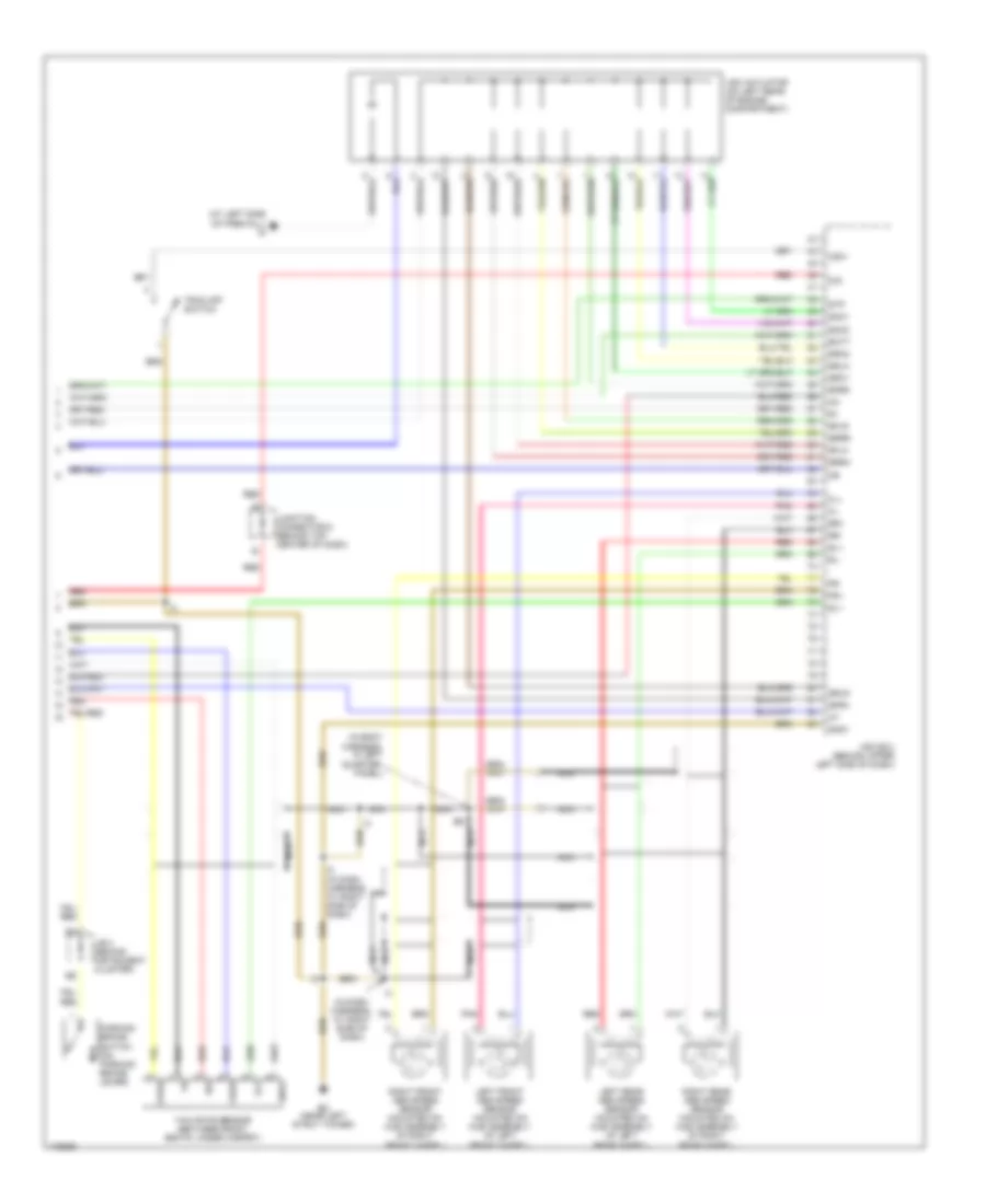
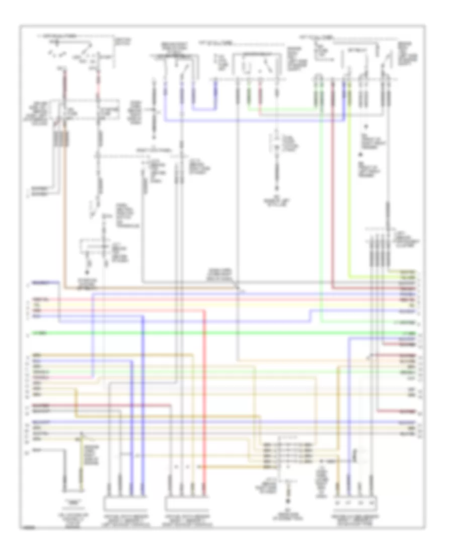
3.0L, Engine Performance Wiring Diagram (2 of 4) for Toyota Sienna CE 2003
List of elements for 3.0L, Engine Performance Wiring Diagram (2 of 4) for Toyota Sienna CE 2003:
- (base of left "b" pillar)
- (behind right side of dash at ecu) a/f heater relay
- (behind right side of dash)
- (dash harn, behind right side of dash)
- (dash harn, lower right end of dash)
- (engine harn, right side of engine)
- A/f htr fuse 25a
- Acc
- Air fuel ratio sensor (bank 1, sensor 1) (right exhaust manifold)
- Air fuel ratio sensor (bank 2, sensor 1) (left exhaust manifold)
- Am2
- B11
- C10
- Cir opn relay
- Driver side j/b 1 (behind dash, left of steering column)
- Ea (front of right front fender)
- Ec (rear side of surge tank)
- Ee (front of left front fender)
- Efi fuse 15a
- Efi relay
- Engine room j/b 2 (left side of engine compt)
- Engine room r/b 1 (left side of engine compt)
- Fuel pump (in fuel tank)
- Heated oxygen sensor (bank 1, sensor 2) (on exhaust pipe)
- Hot at all times
- I11
- I13 (dash harn, lower right end of dash)
- Ig2
- Ign fuse 5a
- Ignition switch
- Ij (right kick panel)
- J/b 3 (behind instrument cluster)
- J/c 13 (behind right side of dash)
- J/c 14
- J/c 6 (behind top center of dash)
- J/c 7 (behind top center of dash)
- Lock
- Nca
- P/n
- Park/ neutral position switch (on transaxle)
- Red
- St2
- Start
- Starter fuse 5a
- Starting system (st relay)
- Vsv (intake air control 2) (top of engine)
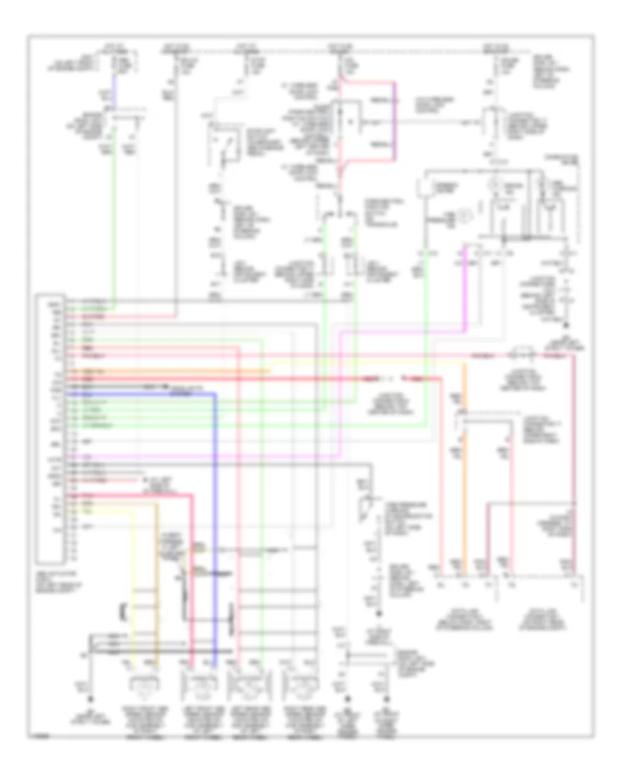
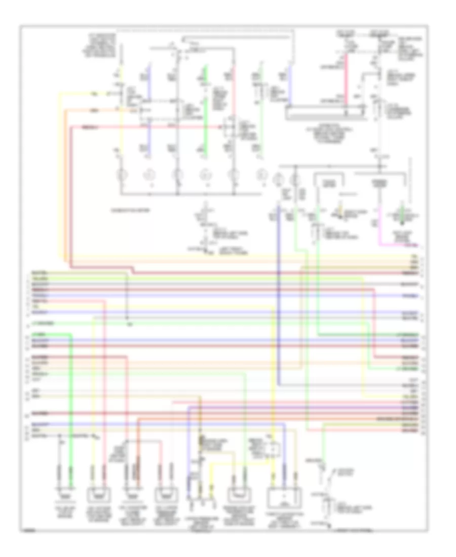
3.0L, Engine Performance Wiring Diagram (3 of 4) for Toyota Sienna CE 2003
List of elements for 3.0L, Engine Performance Wiring Diagram (3 of 4) for Toyota Sienna CE 2003:
- (behind right side of dash) j/c12
- (left front shock tower)
- (right dash brace) ih
- A/t indicator light switch (integral to park/ neutral position switch (on transaxle)
- Anti-lock brake system
- B13
- C10
- C11
- C12
- C13
- Cig fuse 15a
- Combination meter
- D n
- D12
- Diode (p/n) (w/ door lock control) (behind center of dash, taped to harness)
- Driver side j/b 1 (behind dash, left of steering column)
- Engine coolant temperature sensor (on right front side of engine)
- Gauge fuse 10a
- Hot in on or acc
- Hot in on or start
- I8 (dash harn, center of dash)
- Ij (right kick panel)
- J/b 3 (behind inst cluster)
- J/c 17 (behind upper right side of dash)
- J/c 18 (underside of steering column)
- J/c 2
- J/c 2 (behind left side, top of dash)
- J/c 2, 3 (behind left side, top of dash)
- J/c 3
- J/c 7 (behind top center of dash)
- J/c 7 (top center of dash)
- Malf ind lamp
- O/d main switch
- O/d off ind
- Ptnk
- Speedo- meter
- Tacho- meter
- Throttle position sensor (on throttle body assembly)
- Vapor pressure sensor (left side of firewall)
- Vcc
- Vsv (canister closed valve) (left rear of eng compt)
- Vsv (evap) (top of engine)
- Vsv (intake air control) (top center of engine)
- Vsv (vapor pressure sensor) (left rear of eng compt)
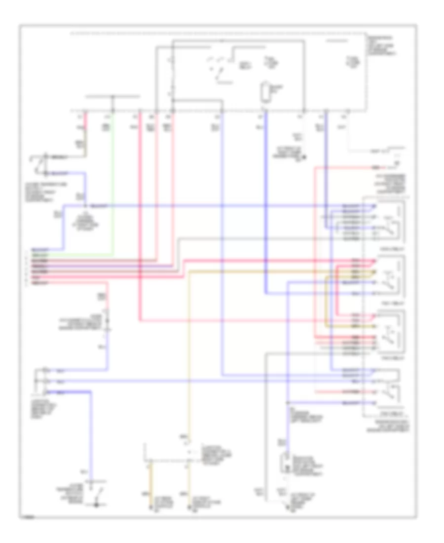
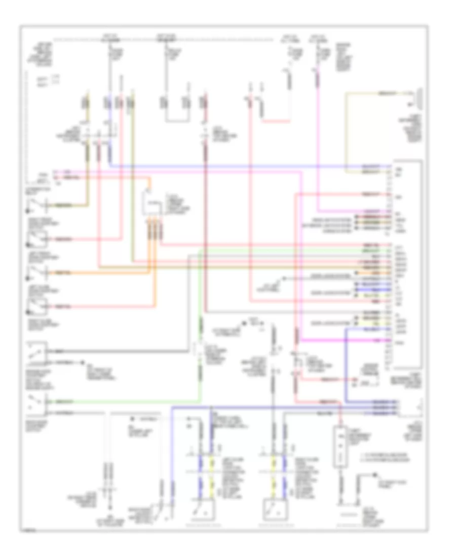
3.0L, Engine Performance Wiring Diagram (4 of 4) for Toyota Sienna CE 2003
List of elements for 3.0L, Engine Performance Wiring Diagram (4 of 4) for Toyota Sienna CE 2003:
- A red
- A/c
- A/c system
- A13
- Acmg
- Anti-lock brakes system
- Anti-theft system
- B18
- Bat
- Batt
- C18
- Ccv
- Code
- Conn e10
- Conn e8
- Conn e9
- Cooling fans system
- Cruise control system
- Data link connector 1 (right rear of engine compt)
- Data link connector 3 (below dash, right of steering column)
- Driver side j/b 1 (behind dash, left of steering column)
- Ec (right side of surge tank)
- Ed (left front shock tower)
- Els
- Els2
- Eng+
- Eng-
- Engine control module (behind right side of dash)
- Eom
- F/ps
- Hot at all times
- Hot w/defogger relay energized
- Hot w/taillight relay energized
- Hts
- I11 (dash harn, behind right side of dash)
- I12 (dash harn, behind left side of dash)
- Idlo
- Igsw
- Ij (right kick panel)
- Imld
- J/b 3 (behind instrument cluster)
- J/c 14 (behind right side of dash)
- J/c 2
- J/c 2, 3 (behind left side, top of dash)
- J/c 3
- J/c 3 (behind left side, top of dash)
- J/c 6 (behind top center of dash)
- J10
- J11
- Ksw
- Mirror- heater fuse 10a
- Mrel
- Neo
- Nsw
- Obd fuse 7.5a
- Od1
- Odlp
- Odms
- Oxs
- Ptnk
- Red
- Red a
- Rxck
- Sil
- Spd
- Sta
- Stop fuse 15a
- Stoplight switch (on bracket, above brake pedal)
- Stp
- Tach
- Tail fuse 10a
- Thwo
- Tpc
- Transponder key amplifier (behind left side of dash)
- Trc+
- Trc-
- Txct
- Unlock warning switch
EXTERIOR LIGHTS
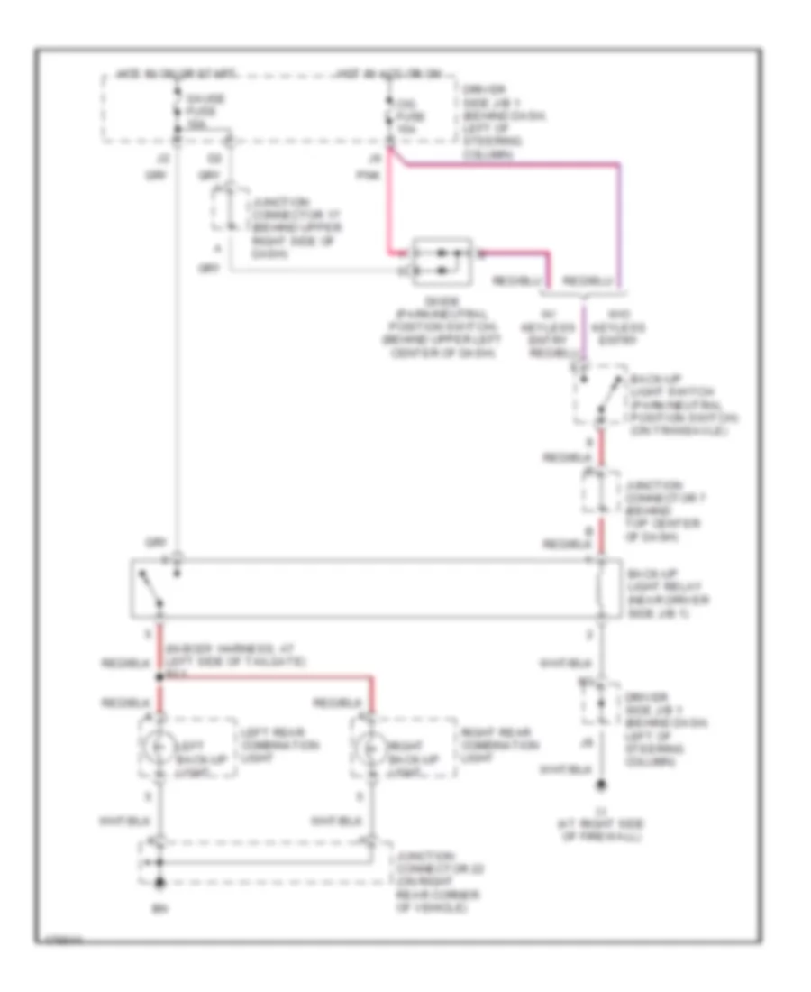
Back-up Lamps Wiring Diagram for Toyota Sienna CE 2003
List of elements for Back-up Lamps Wiring Diagram for Toyota Sienna CE 2003:
- (in body harness, at left side of tailgate) b11
- Back-up light relay (near driver side j/b 1)
- Back-up light switch (park/neutral position switch) (on transaxle)
- Cig fuse 15a
- Diode (park/neutral position switch) (behind upper left center of dash)
- Driver side j/b 1 (behind dash, left of steering column)
- Gauge fuse 10a
- Hot in acc or on
- Hot in on or start
- Ij (at right side of firewall)
- Junction connector 17 (behind upper right side of dash)
- Junction connector 22 (on right rear corner of vehicle)
- Junction connector 7 (behind top center of dash)
- Left back-up light
- Left rear combination light
- Pnk
- Right back-up light
- Right rear combination light
- W/ keyless entry
- W/o keyless entry
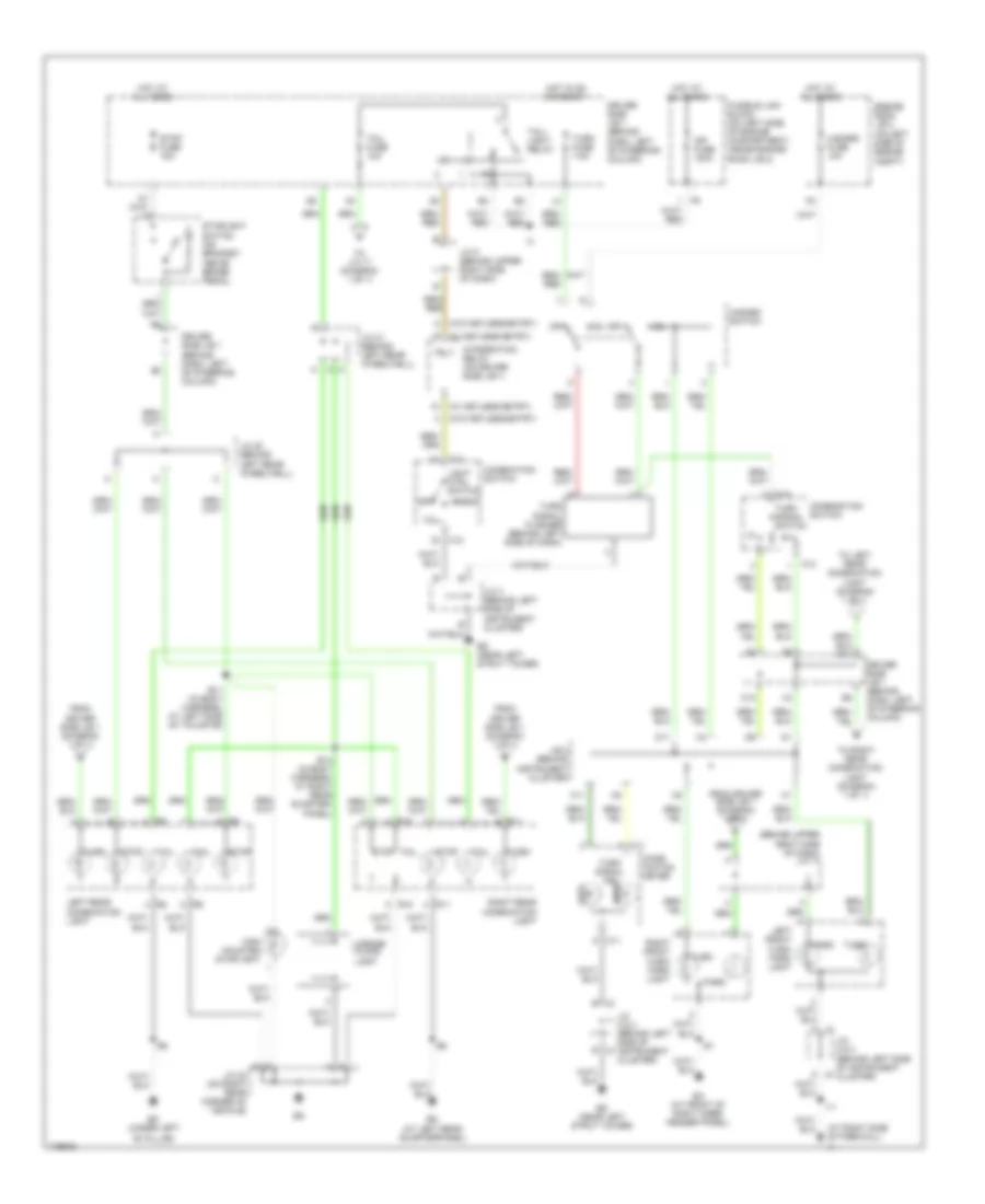
Exterior Lamps Wiring Diagram for Toyota Sienna CE 2003
List of elements for Exterior Lamps Wiring Diagram for Toyota Sienna CE 2003:
- "b" pillar)
- (at right side of firewall) ij
- (behind upper right side of dash) j/c 17
- (w/ keyless entry)
- (w/o keyless entry)
- B11 (in body harness, at left side of tailgate)
- B14 (in body harness, at right rear quarter- panel)
- Bk (under left
- Bm (at left rear quarterpanel)
- C10
- C11
- C12
- Comb- ination meter
- Combination switch
- Combnation switch
- D11
- Driver side j/b 1 (behind dash, left of steering column)
- Ea (at front of right inner fender panel)
- Ed (near left strut tower)
- Engine room j/b 2 (on left side of engine compt)
- From driver side j/b 1 (diagram 1 of 1)
- Fusible link block (on left side of engine compartment, inside engine room j/b 2)
- Hazard fuse 10a
- Hazard switch
- Head
- High mounted stoplight
- Hot at all times
- Hot in on or start
- I11
- Inp fuse 100a
- Integration relay (on driver side j/b 1)
- J/b 3 (behind instrument cluster)
- J/c 2 & 3 (behind left side of instrument cluster)
- J/c 2 & 3 (behind left side of j3 instrument cluster)
- J/c 20 (behind left rear wheelwell)
- J/c 21 (behind left rear wheelwell)
- J/c 22 (on right rear corner of vehicle)
- J/c 3 (behind left side of instrument cluster)
- J/c 5 (behind upper right side of dash)
- Left
- Left front turn/ park light
- Left rear combination light
- License
- Light ctrl switch
- Off
- Park
- Plate light
- R10
- R11
- Right
- Right front turn/ park light
- Right rear combination light
- Stop
- Stop fuse 15a
- Stoplight switch (on bracket, above brake pedal)
- Tail
- Tail fuse 10a
- Tail- light relay
- To j/c 17 (diagram 1 of 1)
- To left rear combination light (diagram 1 of 1)
- To right rear combination light (diagram 1 of 1)
- Trly
- Turn
- Turn fuse 7.5a
- Turn signal flasher (behind left side of dash)
- Turn signal ind
- Turn signal switch
GROUND DISTRIBUTION
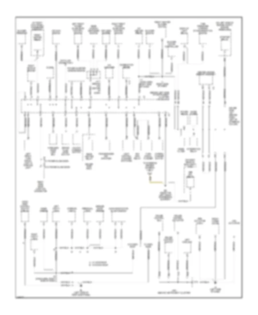
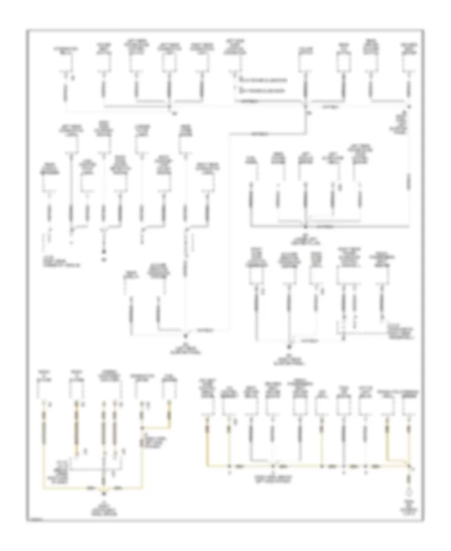
Ground Distribution Wiring Diagram (1 of 3) for Toyota Sienna CE 2003
List of elements for Ground Distribution Wiring Diagram (1 of 3) for Toyota Sienna CE 2003:
- (eng harn, left front corner of eng compt)
- (eng harn, top front of engine) e5
- (on left front of engine compt) r/b 7
- (on left side of engine compt) engine room r/b 1
- (on right rear of engine compt) r/b 8
- Abs actuator & ecu
- B4 (body harness, inside left front door)
- B5 (body harness, inside right front door)
- Cigarette lighter
- Combination meter
- Data link connector 1
- Data link connector 3
- Daytime running light relay (main)
- Drl relay
- E11
- E12
- Ea (front side of right fender apron)
- Eb (right side of surge tank)
- Ec (rear side of surge tank)
- Ee (front side of left fender apron)
- Efi relay
- Engine control module
- Engine hood courtesy switch
- Engine room j/b 2 (on left side of engine compt)
- Fan 1 relay
- Fan 2 relay
- Front power outlet
- Front right door lock control switch
- Heated oxygen sensor (bank 1 sensor 2)
- Idle air control valve
- If (left kick panel)
- Ignition coil & ignitor 1
- Ignition coil & ignitor 2
- Ignition coil & ignitor 3
- Ignition coil & ignitor 4
- Ignition coil & ignitor 5
- Ignition coil & ignitor 6
- Ii (right kick panel)
- J/c 13 (behind lower right side of dash)
- J/c 14 (behind lower right side of dash)
- J/c 8 (behind top center of dash)
- J10
- J15 j/c 15, j/c 16 (behind upper right side of dash)
- J16
- Left front door key lock & unlock switch
- Left front door lock motor & detection switch
- Left remote control mirror
- Main relay 1
- Main relay 2
- Power slide door main switch
- Power window master switch
- Radiator fan motor
- Rear clr relay
- Remote control mirror switch
- Rheostat
- Right foglight
- Right front door key lock & unlock switch
- Right front door lock motor & detection switch
- Right front turn signal & parking light
- Right remote control mirror
- Theft deterrent ecu
- Theft deterrent indicator light
- W/ tow package
- W/o tow package
- Washer level warning switch
- Water temp switch 1
Ground Distribution Wiring Diagram (2 of 3) for Toyota Sienna CE 2003
List of elements for Ground Distribution Wiring Diagram (2 of 3) for Toyota Sienna CE 2003:
- (at right kick panel) passenger side r/b 4
- (behind left side of instrument cluster) j/c 2 & j/c 3
- (on left side of engine compt) engine room j/b 2
- (on right rear of eng compt) r/b 8
- (w/ power slide door) s14
- (w/o power slide door) s14
- A/c amplifier
- A/f heater relay
- Abs actuator & ecu
- Abs sol relay
- Acc main relay
- B10
- Back-up light relay
- Bl (left side of roof side panel)
- Blower motor controller
- Blower resistor
- Blower switch
- Brake fluid level switch
- C10
- C11
- C22
- Center air bag sensor assembly
- Clock
- Combination meter
- Cruise control actuator
- Cruise control ecu
- Cruise control switch
- D22
- Data link connector 3
- Driver side j/b 1 (behind dash, left of steering column)
- Driver side r/b 5
- Ed (near the left front suspension support)
- Front heater blower switch
- Front heater relay
- Front wiper motor
- Garage door opener
- I11 (dash harn, right side of dash)
- I9 (dash harn, right side of dash)
- Ig (left side of dash)
- Ij (right side of dash)
- Inner mirror
- Integration relay
- Interior light 1
- J/b 3 (behind instrument cluster)
- J/c 7 (behind top center of dash)
- Keyless buzzer
- Left foglight
- Left front power slide door control switch
- Left front turn signal light & parking light
- Left vanity light
- Light control & dimmer switches
- Moon roof control switch & relay
- Moon roof motor & limit switch
- Noise filter
- O/d main switch
- Personal light
- Power quarter window switch
- Power relay
- Rear heater relay
- Rear window defogger switch
- Right buckle switch
- Right front power slide door control switch
- Right side door junction connector
- Right vanity light
- Starter relay
- Tire pressure warning standardization switch
- To steering sensor (diagram 3 of 3)
- Transponder key amplifier
- Turn signal flasher
- Unlock warning switch
- Vsc actuator
- W/ moon roof
- W/ moon roof a
- W/o moon roof
- W/o moon roof b
- Wiper & washer switch
- Wireless door lock ecu
Ground Distribution Wiring Diagram (3 of 3) for Toyota Sienna CE 2003
List of elements for Ground Distribution Wiring Diagram (3 of 3) for Toyota Sienna CE 2003:
- (4 speaker)
- (8 speaker)
- (dash harn, behind left side of dash)
- (w/ power slide door)
- (w/o power slide door)
- A/c control assembly
- A25
- Active light relay
- Air vent mode control servo motor
- B8 (body harn, left quarter panel)
- Back door courtesy switch
- Back door key lock/ unlock switch
- Back door unlock detection switch
- Bk (under left center pillar)
- Blower resistor transistor (cooler)
- Blower resistor transistor (heater)
- Bm (left rear quarter panel)
- Bo (right rear quarter panel)
- C10
- Combination meter
- Driver's seat heater
- Driver's seat heater switch
- From ed (diagram 2 of 3)
- Front passenger's seat heater
- Front passenger's seat heater switch
- Fuel pump
- Fuel sender
- High mounted stop- light
- I16
- I6 (dash harn, left side of dash)
- Ih (right instrument panel brace)
- Integration relay
- J/c 15, j/c 16 (behind upper right side of dash)
- J/c 22 (right rear corner of vehicle)
- J/c 23 (forward of right rear fenderwell)
- J15
- J16
- Left buckle switch
- Left rear combination light
- Left rear power slide control switch
- Left rear power slide door control switch
- Left side door junction connector
- Left slide door ecu
- License plate light
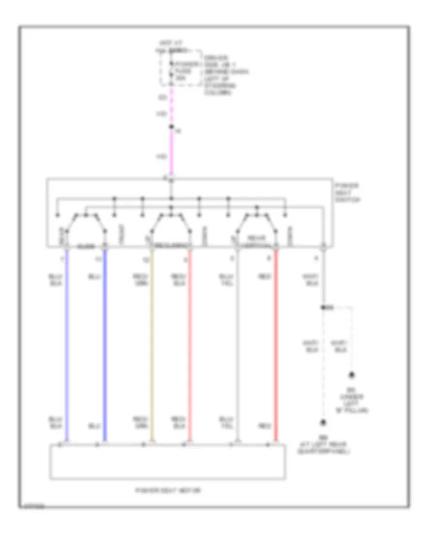
- Power seat switch
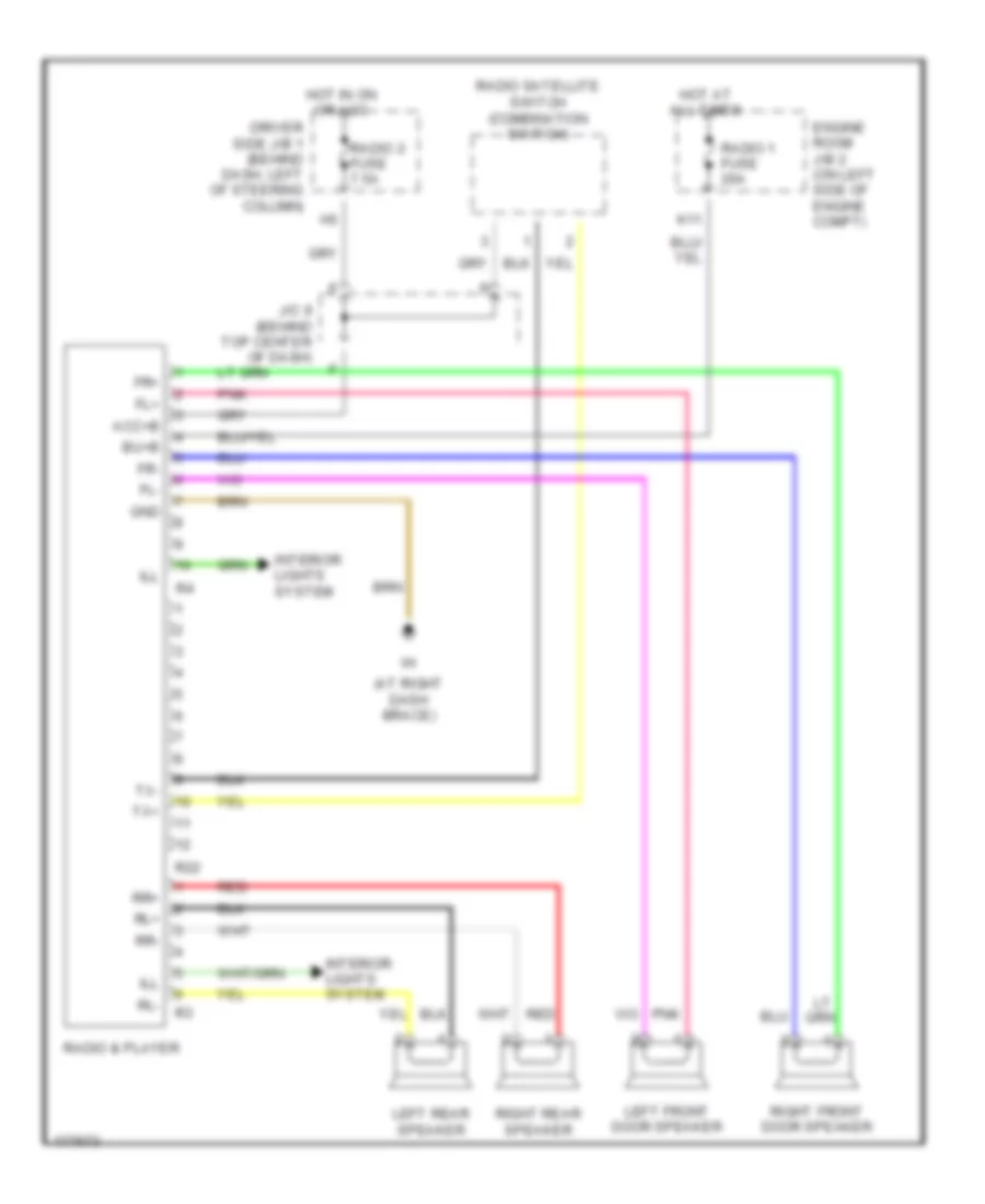
- Radio & player
- Rear a/c switch
- Rear heater blower switch
- Rear hi relay
- Rear power outlet
- Rear window defogger
- Rear wiper motor
- Right rear combination light
- Right rear power slide door control switch
- Right slide door ecu
- Right slide door junction connector
- S12
- S14
- S29
- S31
- Seat heater relay
- Steering sensor
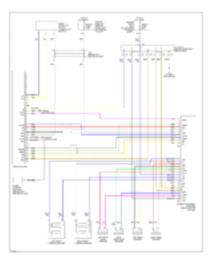
- Stereo component amplifier
- Trac off switch
- Translate ecu
- Volume switch
- Vsc ecu
HEADLIGHTS
Headlights Wiring Diagram (1 of 2) for Toyota Sienna CE 2003
List of elements for Headlights Wiring Diagram (1 of 2) for Toyota Sienna CE 2003:
- (at right side of firewall) ij
- (in dash harness, at left side of dash) i14
- (near left strut tower) ed
- (w/o vsc)
- Abs actuator & ecu (on left rear of engine compt)
- Anti-lock brakes system
- Auto
- Automatic light control sensor (on top left side of dash)
- B19
- Brake fluid level warning switch (on brake fluid reservoir)
- Brake indicator
- Brk
- C10
- C11
- Chg-
- Cltb
- Clte
- Clts
- Combination meter
- Combination switch
- Csb
- Cse
- Cso
- Daytime running light relay (main) (behind dash, right of steering column)
- Dcty
- Dim
- Dimmer switch
- Dome fuse 10a
- Driver side j/b 1 (behind dash, left of steering column)
- Drl
- Engine room j/b 2 (on left side of engine compartment)
- Exterior lights system
- Flash
- Fog
- Foglight switch
- Gauge fuse 10a
- H-lp
- Head
- Head relay
- High
- High beam indicator
- Hot at all times
- Hot in on or start
- Hrly
- I11
- Ij (at right side of firewall)
- Ind
- Integration relay
- J/b 3 (behind instrument cluster)
- J12
- Junction connector 17 (behind upper right side of dash)
- Junction connector 18 (on underside of steering column)
- Junction connector 2 & 3 (behind left side of instrument cluster)
- Left front door courtesy switch
- Light control switch
- Low
- Main fuse 40a
- Off
- Parking brake switch (on parking brake lever)
- Pkb
- Red
- Starting/ charging system
- Tail
- Trly
- V10
- W/ door lock control
- W/ vsc
- W/o door lock control
- W/o vsc
Headlights Wiring Diagram (2 of 2) for Toyota Sienna CE 2003
List of elements for Headlights Wiring Diagram (2 of 2) for Toyota Sienna CE 2003:
- A14
- A15
- C10
- D22
- Daytime running light diode 2 (behind upper left center of dash)
- Dim relay
- Drl relay
- E1 (in engine harness, behind left headlight)
- Ea (at front of right inner fender panel)
- Ee (at front of left inner fender panel)
- Engine room j/b 2 (on left side of engine compartment)
- Fog fuse 20a
- Foglight relay (behind right side of dash)
- H-lp lh lo fuse 10a
- H-lp rh lo fuse 10a
- Head left fuse 15a
- Head right fuse 15a
- Hot at all times
- Ig (at left side of firewall)
- J/b 3 (behind instrument cluster)
- Junction connector 1 (on left front of engine compt, near left headlight)
- Junction connector 7 (behind top center of dash)
- Left foglight
- Left headlight
- R/b 7 (on left front of engine compt)
- Red
- Right foglight
- Right headlight
HORN
Horn Wiring Diagram for Toyota Sienna CE 2003
List of elements for Horn Wiring Diagram for Toyota Sienna CE 2003:
- Combination switch
- Engine room j/b 2 (on left side of engine compartment)
- High horn
- Horn
- Horn fuse 10a
- Horn relay
- Horn switch
- Hot at all times
- Junction connector 18 (on underside of steering column)
- K10
- Low horn
- Sh-
- Theft deterrent ecu (behind center of dash)
- Theft deterrent horn (on right rear of engine compt)
INSTRUMENT CLUSTER
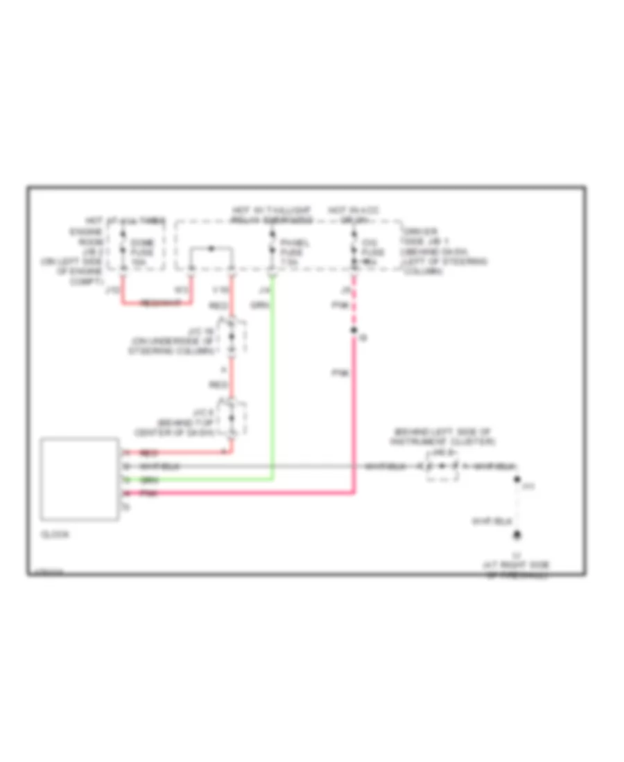
Clock Wiring Diagram for Toyota Sienna CE 2003
List of elements for Clock Wiring Diagram for Toyota Sienna CE 2003:
- (behind left side of instrument cluster) j/c 2
- Cig fuse 15a
- Clock
- Dome fuse 10a
- Driver side j/b 1 (behind dash, left of steering column)
- Engine room j/b 2 (on left side of engine compt)
- Hot at all times
- Hot in acc or on
- Hot w/ taillight relay energized
- I11
- Ij (at right side of firewall)
- J/c 18 (on underside of steering column)
- J/c 6 (behind top center of dash)
- J12
- Panel fuse 7.5a
- Pnk
- Red
- V10
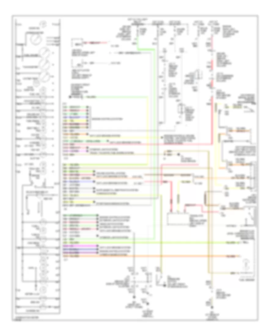
Instrument Cluster Wiring Diagram for Toyota Sienna CE 2003
List of elements for Instrument Cluster Wiring Diagram for Toyota Sienna CE 2003:
- (on parking brake lever) parking brake switch
- (on right front of engine) water temperature sender
- (or red)
- (w/ vsc)
- (w/o vsc)
- A red a
- A10
- A11
- A12
- A13
- A14
- A15
- A16
- Abs actuator & ecu (on left rear of engine compt)
- Abs ind
- Anti-lock brakes system
- B10
- B11
- B12
- B13
- B19
- Brake fluid level warning switch (on brake fluid reservoir)
- Brake ind
- Brl
- Bulb check relay
- C10
- C11
- C12
- C13
- Charge ind
- Combination meter
- Cruise control system
- Cruise ind
- Daytime running light relay (main) (behind dash, right of steering column)
- Dome fuse 10a
- Door ind
- Driver side j/b 1 (behind dash, left of steering column)
- Ebdw
- Ec (at rear of intake manifold)
- Ecu-b fuse 10a
- Ed (near left strut tower)
- Engine controls system
- Engine controls, cruise control, air conditioning & trunk, tailgate, fuel doors systems
- Engine room j/b 2 (on left side of engine compt)
- Exterior lights system
- Fuel gauge
- Fuel ind
- Fuel sender
- Gauge fuse 10a
- Headlights system
- High beam ind
- Hot at all times
- Hot in on or start
- Hot w/ taillight relay energized
- I11
- Ign fuse 5a
- Ih (at right dash brace)
- Ij (at right side of firewall)
- Interior lights system
- J/b 3 (behind instrument cluster)
- J/c 17 (behind upper right side of dash)
- J/c 18 (on under- side of steering column)
- J/c 18 (on underside of steering column)
- J/c 2 & 3 (behind left side of instrument cluster)
- J/c 6 (behind top center of dash)
- J/c 8 (behind top center of dash)
- J12
- J2 a
- J2 b
- J3 a
- J3 b
- Malfunction ind lamp
- Meter illum
- O/d off ind
- Oil ind
- Oil pressure switch (on left front of engine block)
- Panel fuse 7.5a
- Pwr
- Red
- Seat belt ind
- Slip ind
- Speedometer
- Srs ind
- Starting/charging system
- Tachometer
- Tire press ind
- Trac off ind
- Translate ecu (behind upper left side of dash)
- Trunk, tailgate, fuel doors system
- Turn l ind
- Turn r ind
- V10
- Vsc ecu (behind upper left side of dash)
- Vsc ind
- W/ vsc
- W/o vsc
- Warning system
- Washer ind
- Water temp
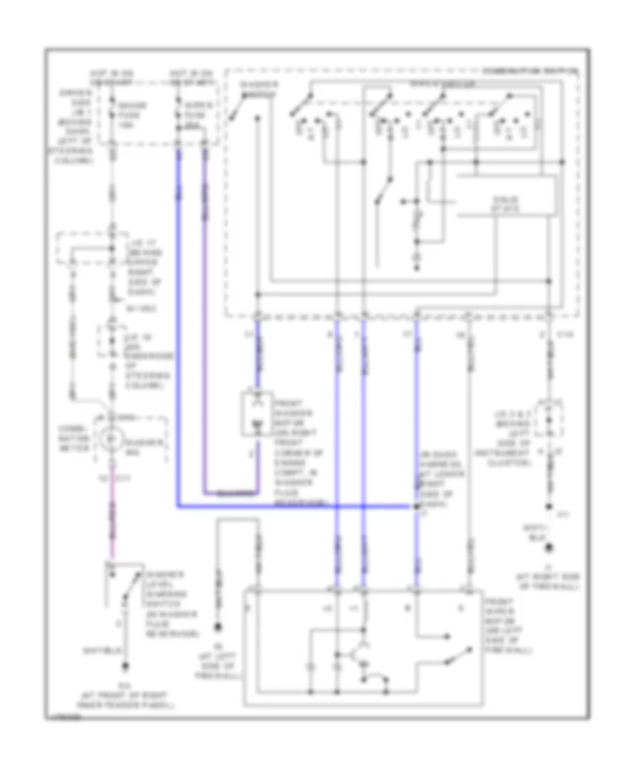
- Wiper/washer system
INTERIOR LIGHTS
Courtesy Lamps Wiring Diagram, with Door Locks (1 of 2) for Toyota Sienna CE 2003
List of elements for Courtesy Lamps Wiring Diagram, with Door Locks (1 of 2) for Toyota Sienna CE 2003:
- (in body harness, at center of windshield header) b1
- Bl (w/ moon roof) (at left side of roof side panel)
- Diode (dome 4) (behind upper left center of dash)
- Dome fuse 10a
- Door
- Dout
- Driver side j/b 1 (behind dash, left of steering column)
- Engine room j/b 2 (on left side of engine compt)
- Gauge fuse 10a
- Hot at all times
- Hot in on or start
- I13
- Ig (w/o moon roof) (at left side of firewall)
- Integration relay
- Interior light 1 (w/ vanity light)
- Interior light 1 (w/o vanity light)
- Interior light 2
- J12
- Junction connector 18 (on underside of steering column)
- Junction connector 9 (behind top center of dash)
- Left front door courtesy light
- Left vanity light (w/ vanity light)
- M2 red
- Off
- Pcty
- Personal light (w/ vanity light)
- Personal light (w/o vanity light)
- Red
- Right front door courtesy light
- Right vanity light (w/ vanity light)
- V10 red
- W/ vanity lights
- W/ fade out type
- W/o moon roof
Courtesy Lamps Wiring Diagram, with Door Locks (2 of 2) for Toyota Sienna CE 2003
List of elements for Courtesy Lamps Wiring Diagram, with Door Locks (2 of 2) for Toyota Sienna CE 2003:
- A10
- B10 (in body harness, at left rear quarterpanel)
- B12
- Back door courtesy switch
- Bcty
- C10
- Combination meter
- D19
- Dcty
- Diode (courtesy 2) (on left rear of vehicle, naer left rear wheelwell)
- Diode (courtesy 3) (behind upper left center of dash)
- Diode (dome 5) (behind upper left center of dash)
- Door fuse 25a
- Driver side j/b 1 (behind dash, left of steering column)
- Hot at all times
- I1 (in dash harenss, at left side of dash)
- I13
- I16
- Ignition key cylinder light
- Ij (at right side of firewall)
- Integration relay
- J/b 3 (behind instrument cluster)
- Junction connector 18 (on underside of steering column)
- Junction connector 22 (on right rear corner of vehicle)
- Junction connector 5 (behind upper right side of dash)
- Junction connector 6 (behind top center of dash)
- Left front door courtesy switch
- Left slide door courtesy light
- Left slide door courtesy switch
- Luggage compartment light
- Open door warning light
- Red
- Right front door courtesy switch
- Right slide door courtesy light
- Right slide door courtesy switch
- Scty
- Wrn
Courtesy Lamps Wiring Diagram, without Door Locks (1 of 2) for Toyota Sienna CE 2003
List of elements for Courtesy Lamps Wiring Diagram, without Door Locks (1 of 2) for Toyota Sienna CE 2003:
- (in body harness, at center of windshield header) b1
- (on underside of steering column) junction connector 18
- Bl (w/ moon roof) (at left side of roof side panel)
- D18
- Dcty
- Dome fuse 10a
- Door
- Driver side j/b 1 (behind dash, left of steering column)
- Engine room j/b 2 (on left side of engine compt)
- Except fade out type
- Gauge fuse 10a
- Hot at all times
- Hot in on or start
- I13
- Ig (w/o moon roof) (at left side of firewall)
- Ignition key cylinder light
- Ij (at right side of firewall)
- Integration relay
- Interior light 1 (w/ vanity light)
- Interior light 1 (w/o vanity light)
- Interior light 2
- J/b 3 (behind instrument cluster)
- J12
- Junction connector 18 (on underside of steering column)
- Junction connector 9 (behind top center of dash)
- Left front door courtesy light
- Left vanity light (w/ vanity light)
- M2 red
- Off
- Pcty
- Personal light (w/ vanity light)
- Personal light (w/o vanity light)
- Red
- Red red
- Right front door courtesy light
- Right vanity light (w/ vanity light)
- Scty
- V10 red
- W/o moon roof
- W1 red
Courtesy Lamps Wiring Diagram, without Door Locks (2 of 2) for Toyota Sienna CE 2003
List of elements for Courtesy Lamps Wiring Diagram, without Door Locks (2 of 2) for Toyota Sienna CE 2003:
- (in body harness, at left rear quarterpanel) b10
- A10
- A16
- B12
- B15
- Back door courtesy switch
- C10
- C14
- C17
- Combination meter
- D15
- D16
- D17
- D19
- Diode (courtesy 2) (on left rear of vehicle, near left rear wheelwell)
- Diode (dome 1) (behind upper left center of dash)
- Diode (dome 2) (behind upper left center of dash)
- Diode (dome 3) (behind upper left center of dash)
- Door fuse 25a
- Driver side j/b 1 (behind dash, left of steering column)
- Hot at all times
- I1 (in dash harness, at left side of dash)
- J/b 3 (behind instrument cluster)
- Junction connector 22 (on right rear corner of vehicle)
- Junction connector 6 (behind top center of dash)
- Left front door courtesy switch
- Left slide door courtesy light
- Left slide door courtesy switch
- Luggage compartment light switch
- Open door warning light
- Red
- Right front door courtesy switch
- Right slide door courtesy switch
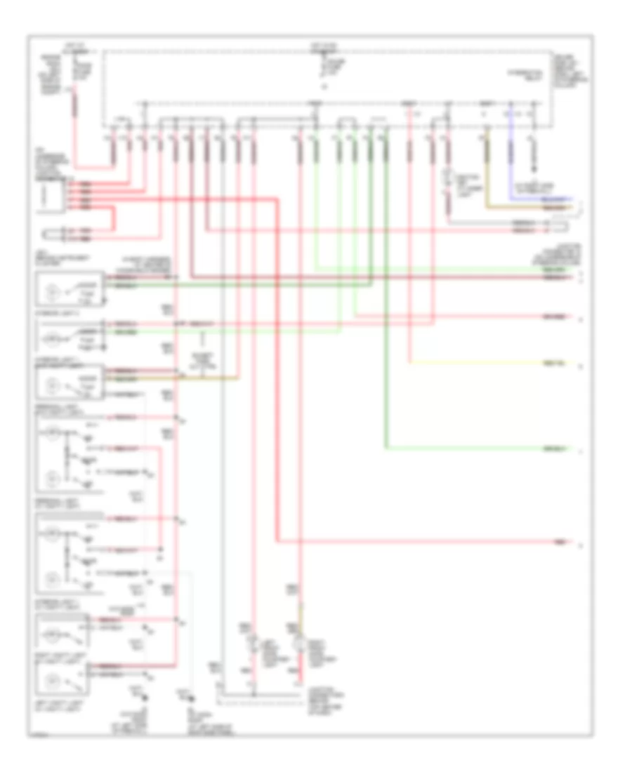
Instrument Illumination Wiring Diagram for Toyota Sienna CE 2003
List of elements for Instrument Illumination Wiring Diagram for Toyota Sienna CE 2003:
- (4 spkr)
- (8 spkr)
- (automatic a/c)
- (w/ door lock control)
- (w/o door lock control)
- A/c control assembly
- A/c switch
- A24
- A25
- Ashtray illumination
- Bk (under left "b" pillar)
- Blower switch
- Bo (at right rear quarterpanel)
- C11
- C12
- Clock
- Combi- nation meter illu- mination (combi- nation meter)
- Driver side j/b 1 (behind dash, left of steering column)
- Ed (near left strut tower)
- Front heater blower switch
- Fusible link block (on left side of engine compt, inside engine room j/b 2)
- Hazard switch
- Head
- Hot at all times
- I9 (in dash harness, at center of dash)
- If (at left kick panel)
- Ij (at right side of firewall)
- Ill-
- Inp fuse 100a
- Instrument panel j/b
- Integration trly
- Junction connector 2 (behind left side of instrument cluster)
- Junction connector (behind left rear wheelwell)
- Junction connector (forward of right rear fenderwell)
- Junction connector 11 (behind upper right side of dash)
- Junction connector 3 (behind left side of instrument cluster)
- Junction connector 4 (behind upper left side of dash)
- Junction connector 5 (behind upper right side of dash)
- Junction connector 9 (behind top center of dash)
- Left front power slide door control switch
- Left front seat heater switch
- Left rear power slide door control switch
- Light control switch (combination switch)
- Off
- Panel fuse 7.5a
- Power quarter window switch
- Power slide door main switch
- Radio & player
- Rear a/c switch (automatic a/c)
- Rear heater blower switch (manual a/c)
- Rear window defogger switch
- Relay (on driver side j/b 1)
- Rheostat
- Right front power slide door control switch
- Right front seat heater switch
- Right rear power slide door control switch
- Tail
- Tail fuse 10a
- Taillight relay
POWER DISTRIBUTION
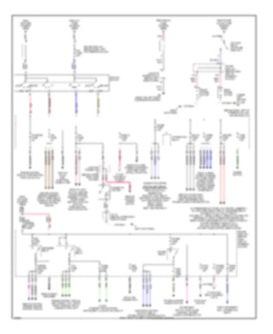
Power Distribution Wiring Diagram (1 of 3) for Toyota Sienna CE 2003
List of elements for Power Distribution Wiring Diagram (1 of 3) for Toyota Sienna CE 2003:
- (diagram 2 of 3)
- (diagram 3 of 3)
- (on left side of engine compt) engine room j/b 2
- (on left side of engine compt) engine room r/b 1
- A b
- A w/o tow package
- A/c amplifier, a/c switch
- A/c condenser fan motor
- A/c fuse 5a
- A/f heater relay
- A/f htr fuse 25a
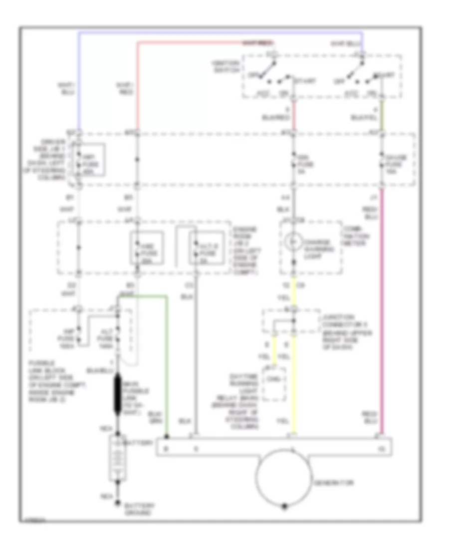
- Alt fuse 140a
- Alt-s fuse 5a
- Am2 fuse 30a
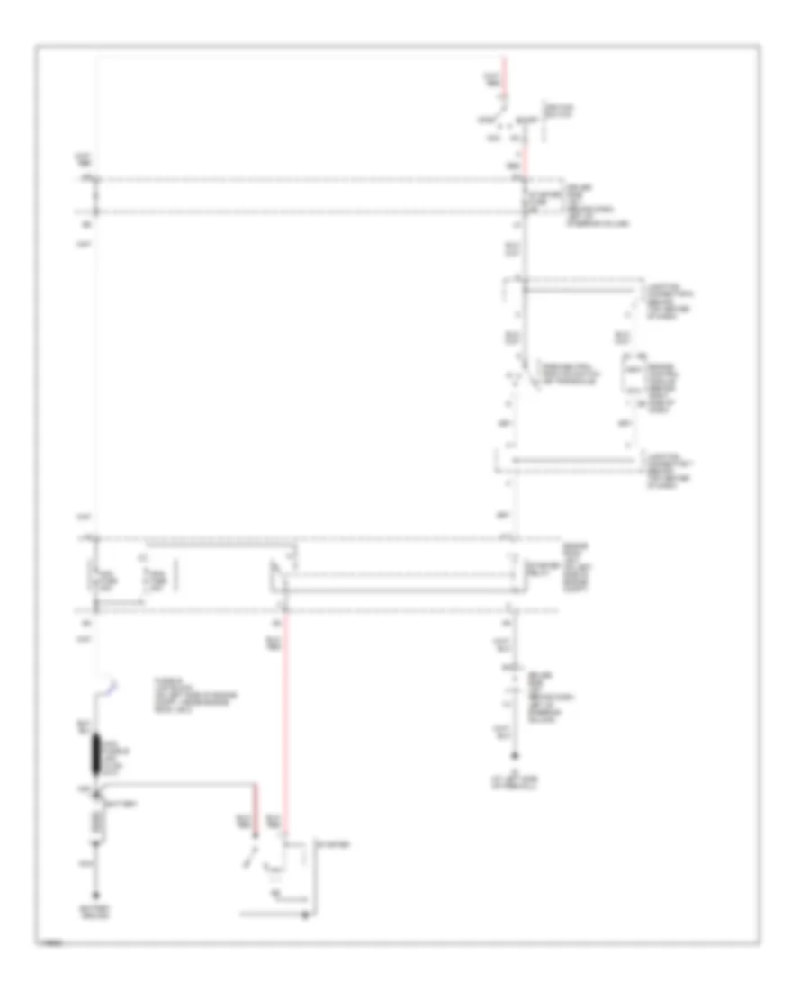
- Battery
- Blower motor
- C10
- Cds fuse 30a 40a
- Combination meter, clock, a/c control assembly, courtesy diodes, daytime running light relay (main), garage door opener, interior & courtesy lights,
- Combination meter, left slide door ecu
- Data link connector 1, engine control module, vsv, heated oxygen sensor (bank 1 sensor 2), idle air control valve, mass airflow meter, circuit open relay, transponder key amplifier
- Dim relay
- Dome fuse 10a
- Driver side r/b 5 (behind left side of dash)
- Ecu-b fuse 10a
- Efi fuse 15a
- Efi relay
- Engine control module
- Engine room j/b 2 (on left side of engine compt)
- Engine room r/b 1 (left side of eng compt)
- Fan 1 relay
- Fan 3 relay
- From c radio 1 fuse (diagram 1 of 3)
- Front heater relay
- Fusible link block (on left side of engine compt)
- Generator
- Hazard fuse 10a
- Hazard switch
- Head relay
- Headlights
- Horn fuse 10a
- Horn relay
- Horn switch
- Horns
- Htr fuse 50a
- Inp fuse 100a
- Integration relay, theft deterrent ecu, wireless door lock ecu, personal
- J12
- Junction connector 1 (near left headlight)
- K10
- K11
- Left head fuse 15a
- Left head lower fuse 10a
- Left low beam head- light
- Light, ignition key cylinder light
- Main
- Main fuse 40a
- Main relay 1
- Passenger side r/b 4 (at right kick panel)
- R/b 7 (on left front of eng compt)
- Radiator fan motor
- Radio & player, stereo component amplifier
- Radio 1 fuse 20a
- Rdi fuse 30a
- Rdi fuse 40a
- Rear heater relay
- Red
- Relay 2
- Right head fuse 15a
- Right head lower fuse 10a
- Right low beam head- light
- Rr a/c fuse 40a
- S/htr fuse 20a
- Seat heater relay
- Short pin
- Theft deterrent ecu
- To abs fuse
- To am1 fuse (diagram 2 of 3)
- To hazard fuse (diagram 1 of 3)
- To i4 splice
- To ignition switch (diagram 2 of 3)
- W/ tow package b
Power Distribution Wiring Diagram (2 of 3) for Toyota Sienna CE 2003
List of elements for Power Distribution Wiring Diagram (2 of 3) for Toyota Sienna CE 2003:
- (behind dash, left of steering column) driver side j/b 1
- (under left center pillar) bk
- A/c pressure switches, a/c control assembly, a/c amplifier, rear hi relay, defogger relay, fan relays 2 & 3, mg clt relay, main relay 1, rear lo relay, rear m1 & m2 relays, rear relay, front & rear heater relays, rear window defogger switch, rear clr relay, water temperature switch 1, air inlet control servo motor, air vent mode control servo motor
- Abs actuator & ecu, cruise control ecu, theft deterrent ecu, power window master switch
- Acc
- Acc main relay (on driver side j/b 1)
- Active light relay, diode (park/neutral position switch), generator, back-up light relay, left/right slide door ecu, daytime running light relay (main), inner mirror, seat heater relay
- Am1 fuse 40a
- Back-up light switch, center air bag sensor assembly, clock, diode (park/ neutral positon switch), park/neutral position switch
- Center air bag sensor assembly, circuit open relay, combination meter, engine control module
- Cig fuse 15a
- Cigarette lighter
- Clock, interior lights system (instrument illumination circuit)
- Combination meter,
- D pnk
- Data link connector 3
- Def fuse 30a
- Defogger relay
- Door fuse 25a
- Driver side j/b 1 (behind dash, left of steering column)
- Ecu-ig fuse 15a
- Ed (near the left front suspension support)
- Engine control module, left & right tail lights, front parking lights, license plate light
- Engine control module, park/neutral position switch
- From alt fuse (diagram 1 of 3)
- From am2 fuse (diagram 1 of 3)
- From inp fuse (diagram 1 of 2)
- From power outlet fuse (diagram 2 of 3)
- From radio 2 fuse (diagram 2 of 3)
- Front & rear wiper & washer switches, front & rear wiper motors, front & rear washer motors, rear wiper relay
- Front power outlet
- G12
- G13
- Gauge fuse 10a
- H10
- Hazard switch
- Heater fuse 10a
- If (left kick panel)
- Ign fuse 5a
- Ignition coils, fuel injectors, noise filter
- Ignition switch
- Ii (right kick panel)
- Integration relay
- J/c 16 (behind upper right side of dash)
- J10
- J11
- Junction connector (behind upper right side of dash)
- Junction connector j3 (behind left side of dash)
- Left side of side) b4
- Lock
- Mirror heater fuse 10a
- Moon roof control switch & relay, power window master switch, right front power window control switch
- Obd fuse 7.5a
- Panel fuse 7.5a
- Pnk
- Power fuse 30a
- Power quarter window switch
- Power relay
- Power seat switch, right slide door ecu, power window master switch
- Power- outlet fuse 15a
- Pwr- vent fuse 15a
- Radio & player, stereo component amplifier, radio satellite switch
- Radio 2 fuse 7.5a
- Rear power outlet
- Rear window defogger
- Red
- Remote control mirror switch
- Remote control mirrors, engine control module
- S13
- Start
- Starter fuse 5a
- Stop fuse 15a
- Stoplight switch
- Tail fuse 10a
- Tail light relay
- Theft deterrent ecu, integration relay
- To acc main relay (diagram 2 of 3)
- Turn fuse 7.5a
- Wiper fuse 25a
Power Distribution Wiring Diagram (3 of 3) for Toyota Sienna CE 2003
List of elements for Power Distribution Wiring Diagram (3 of 3) for Toyota Sienna CE 2003:
- Abs 2 fuse 25a
- Abs 3 fuse 25a
- Abs fuse 60a
- Abs mtr relay, abs actuator & ecu
- Abs sol relay
- Fog fuse 20a
- Foglight relay
- From alt fuse (diagram 1 of 3)
- Generator
- Left slide door ecu
- Pwr sld fuse 30a
- R/b 7 (left front of engine compt)
- Rear clr relay
- Rr clr fuse 40a
- Vsc ecu
POWER DOOR LOCKS
Power Door Locks Wiring Diagram, with Keyless Entry for Toyota Sienna CE 2003
List of elements for Power Door Locks Wiring Diagram, with Keyless Entry for Toyota Sienna CE 2003:
- (behind center of dash) (w/ anti-theft) theft deterrent ecu
- (behind instrument cluster) j/b 3
- (behind top center of dash)
- (behind upper right side of dash) junction connector 11
- (in body harness, at left "c" pillar)
- A red
- A10
- A16
- Act+
- Act-
- Actd
- B15
- Back door key lock & unlock switch
- Back door lock motor (above center of rear bumper assembly)
- Bm (at left rear quarter- panel)
- Bzr
- C12
- C17
- D14
- D15
- D16
- D19
- Dcty
- Dome fuse 10a
- Door fuse 25a
- Door lock motor
- Driver side j/b 1 (behind dash, left of steering column)
- Ed (near left strut tower)
- Engine room j/b 2 (on left side of engine compt)
- Gauge fuse 10a
- Hot at all times
- Hot in on or start
- I13
- I16
- If (at left kick panel)
- Ii (at right kick panel)
- Ij (at right side of firewall)
- Integration relay
- J/b 3 (behind instr- ument cluster)
- J/b 3 (behind instrument cluster)
- J/c 22 (on right rear corner of vehicle)
- J/c 5 (behind upper right side of dash)
- J12
- J15
- J16
- Junction connector 15 & 16 (behind upper right side of dash)
- Junction connector 18 (on underside of steering column)
- Junction connector 3 (behind left side of instrument cluster)
- Junction connector 4 (behind upper left side of dash)
- Junction connector 6
- Keyless buzzer (behind left front corner lamp)
- Ksw
- Left front door courtesy switch
- Left front door key unlk lock & unlock switch
- Left front door lock motor & unlock detection switch
- Left front door lock unlk control switch (power window master switch)
- Left slide door junction connector (at base of left "b" pillar)
- Lock
- Lsds
- Lswd
- Lswp
- Pcty
- Prg
- Rda
- Red
- Right front door courtesy switch
- Right front door key unlk lock & unlock switch
- Right front door lock motor & unlock detection switch
- Right front door lock unlk control switch
- Right slide door junction connector (at base of right "b" pillar)
- Ul1
- Ul2
- Ul3
- Unlk
- Unlock warning switch
- V10 red a
- W/ anti-theft
- W/ power slide door
- W/o anti-theft
- W/o power slide door
- Wireless door lock ecu (behind center of dash)
Power Door Locks Wiring Diagram, without Keyless Entry for Toyota Sienna CE 2003
List of elements for Power Door Locks Wiring Diagram, without Keyless Entry for Toyota Sienna CE 2003:
- (at left kick panel) if
- (at left rear quarterpanel) bm
- (behind center of dash) (w/ anti-theft) theft deterrent ecu
- (behind upper right side of dash) j/c 5
- (behind upper right side of dash) junction connector 11
- (in body harness, at left "c" pillar)
- +b1
- +b2
- A10
- A16
- Act+
- Act-
- Actd
- B15
- Back door key lock & unlock switch
- Back door lock motor (above center of rear bumper assembly)
- C12
- C17
- D14
- D15
- D16
- D18
- D19
- Dcty
- Dome fuse 10a
- Door fuse 25a
- Door lock motor
- Driver side j/b 1 (behind dash, left of steering column)
- Ed (near left strut tower)
- Engine room j/b 2 (on left side of engine compt)
- G2 red
- Gauge fuse 10a
- Hot at all times
- Hot in on or start
- I13
- I16
- If (at left kick panel)
- Ii (at right kick panel)
- Integration relay
- J/b 3 (behind instr- ument cluster)
- J/b 3 (behind instrument cluster
- J/b 3 (behind instrument cluster)
- J/c 22 (on right rear corner of vehicle)
- J/c 5 (behind upper right side of dash)
- J15
- J16
- Junction connector 15 & 16 (behind upper right side of dash)
- Junction connector 3 (behind left side of instrument cluster)
- Junction connector 4 (behind upper left side of dash)
- Junction connector 6 (behind top center of dash)
- Ksw
- Left front door courtesy switch
- Left front door key unlk lock & unlock switch
- Left front door lock motor & unlock detection switch
- Left front door lock unlk control switch (power window master switch)
- Left slide door junction connector (at base of left "b" pillar)
- Lock
- Lsds
- Lswd
- Lswp
- Pcty
- Red
- Right front door courtesy switch
- Right front door key unlk lock & unlock switch
- Right front door lock motor & unlock detection switch
- Right front door lock unlk control switch
- Right slide door junction connector (at base of right "b" pillar)
- Ul1
- Ul2
- Ul3
- Unlk
- Unlock warning switch
- W/ anti-theft
- W/ power slide door
- W/o anti-theft
- W/o power slide door
POWER MIRRORS
Electrochromic Mirror Wiring Diagram for Toyota Sienna CE 2003
List of elements for Electrochromic Mirror Wiring Diagram for Toyota Sienna CE 2003:
- (behind dash left of steering column)
- Bl (at left side of roof side panel)
- Driver side j/b 1
- Driver side j/b 1 (behind dash left of steering column)
- Gauge fuse 10a
- Hot in on or start
- Ig (at left side of firewall)
- Ig ig
- Inner mirror
- W/ moon roof
- W/o moon roof
Power Mirrors Wiring Diagram for Toyota Sienna CE 2003
List of elements for Power Mirrors Wiring Diagram for Toyota Sienna CE 2003:
- Cig fuse 15a
- D j16
- Defogger system
- Down
- Driver side j/b 1 (behind dash, left of steering column)
- Hot in acc or on
- If (at left kick panel)
- Ii (at right kick panel)
- J15
- Junction connector 11 (behind upper right side of dash)
- Junction connector 15 & 16 (behind e j15
- Junction connector 15 (behind upper right side of dash)
- Left
- Left remote control mirror
- Operation switch
- Pnk
- Remote control mirror switch
- Right
- Right remote control mirror
- Select switch
- Upper right side of dash)
POWER SEATS
Heated Seats Wiring Diagram for Toyota Sienna CE 2003
List of elements for Heated Seats Wiring Diagram for Toyota Sienna CE 2003:
- (at left rear quarterpanel) bm
- (at right rear quarterpanel) bo
- (behind instrument cluster) j/b 3
- (behind upper right side of dash) junction connector 17
- (near left strut tower) ed
- (under left "b" pillar) bk
- D20
- Driver side j/b 1 (behind dash, left of steering column)
- Driver's seat heater
- Driver's seat heater switch
- Engine room r/b 1 (on left side of engine compt)
- Front passenger's seat
- Front passenger's seat heater
- Front passenger's seat heater switch
- Gauge fuse 10a
- Hot at all times
- Hot in on or start
- Ill
- Interior lights system
- Junction connector 23 (forward of right rear fenderwell)
- Junction connector 8 (behind top center of dash)
- S/htr fuse 20a
- Seat heater relay (behind left side of dash)
Power Seat Wiring Diagram for Toyota Sienna CE 2003
List of elements for Power Seat Wiring Diagram for Toyota Sienna CE 2003:
- Bk (under left "b" pillar)
- Bm (at left rear quarterpanel)
- Down
- Driver side j/b 1 (behind dash, left of steering column)
- Front
- Hot at all times
- Power fuse 30a
- Power seat motor
- Power seat switch
- Rear
- Rear vertical
- Reclining
- Red
- Slide
POWER TOP/SUNROOF
Moonroof Wiring Diagram for Toyota Sienna CE 2003
List of elements for Moonroof Wiring Diagram for Toyota Sienna CE 2003:
- A10
- Bl (at left side of roof side panel)
- D19
- Dcty
- Door fuse 25a
- Driver side j/b 1 (behind dash, left of steering column)
- Gauge fuse 10a
- Hot at all times
- Hot in on or start
- I13
- Ij (at right side of firewall)
- Integration relay
- J/b 3 (behind instrument cluster)
- Left front door courtesy switch
- Limit switches
- Moon roof control switch & relay (on front center of windshield header)
- Moon roof motor & limit switch (on center underside front of roof)
- Motor
- P/w
- Pcty
- Power relay
- Power fuse 30a
- Red
- Right front door courtesy switch
- Slide open
- Tilt up
POWER WINDOWS
Power Windows Wiring Diagram for Toyota Sienna CE 2003
List of elements for Power Windows Wiring Diagram for Toyota Sienna CE 2003:
- (at left kick panel)
- (behind left rear wheelwell) j/c 20
- A10
- B j2
- Cls
- D19
- Dcty
- Door fuse 25a
- Down
- Driver side j/b 1 (behind dash, left of steering column)
- Ecu-ig fuse 15a
- Ed (near left strut tower)
- G12
- G13
- Gauge fuse 10a
- Hot at all times
- Hot in on or start
- I13
- Ij (at right side of firewall)
- Integration relay
- J/b 3 (behind left side of instrument cluster)
- J/c 2, j/c 3 (behind left side of instrument cluster)
- J/c 9 (behind top center of dash)
- J3 b
- Left front door courtesy switch
- Left front power window motor
- Left power vent window motor
- Open
- P/w
- Pcty
- Power fuse 30a
- Power quarter window switch
- Power relay
- Power window master switch
- Pwr-vent fuse 15a
- Red
- Right front door courtesy switch
- Right front power window control switch
- Right front power window motor
- Right power vent window motor
- Top center
RADIO
Radio Wiring Diagram, with Built-in Amplifier for Toyota Sienna CE 2003
List of elements for Radio Wiring Diagram, with Built-in Amplifier for Toyota Sienna CE 2003:
- (at right dash brace)
- Acc+b
- Bu+b
- Driver side j/b 1 (behind dash, left of steering column)
- Engine room j/b 2 (on left side of engine compt)
- Fl+
- Fl-
- Fr+
- Fr-
- Gnd
- Hot at all times
- Hot in on or acc
- Ill
- Interior lights system
- J/c 9 (behind top center of dash)
- K11
- Left front door speaker
- Left rear speaker
- Pnk
- R22
- Radio & player
- Radio 1 fuse 20a
- Radio 2 fuse 7.5a
- Radio satellite switch (combination switch)
- Red
- Right front door speaker
- Right rear speaker
- Rl+
- Rl-
- Rr+
- Rr-
- Tx+
- Tx-
Radio Wiring Diagram, with Separate Amplifier for Toyota Sienna CE 2003
List of elements for Radio Wiring Diagram, with Separate Amplifier for Toyota Sienna CE 2003:
- +b2
- A j15
- A j16
- Acc
- Amp
- Amp+
- Ant
- Beep
- C j15
- C j16
- Driver side j/b 1 (behind dash, left of steering column)
- Engine room j/b 2 (on left side of engine compt)
- Fl+
- Fl-
- Fr+
- Fr-
- Glass antenna amplifier (behind left center of dash)
- Gnd
- Gnd(s)
- Hot at all times
- Hot in on or acc
- Ih (at right dash brace)
- Illum
- Interior lights system
- J/c 15 & 16 (behind upper right side of dash)
- J/c 9 (behind top center of dash)
- K11
- Left front door speaker
- Left front tweeter speaker
- Left rear speaker
- Mute
- Nca
- Pnk
- R22
- Radio & player
- Radio 1 fuse 20a
- Radio 2 fuse 7.5a
- Radio satellite switch (combination switch)
- Red
- Right front door speaker
- Right front tweeter speaker
- Right rear speaker
- Rl+
- Rl-
- Rr+
- Rr-
- Sgnd
- Stereo component amplifier (behind center of dash)
- Tx+
- Tx-
- Wfl+
- Wfl-
- Wfr+
- Wfr-
STARTING/CHARGING
Charging Wiring Diagram for Toyota Sienna CE 2003
List of elements for Charging Wiring Diagram for Toyota Sienna CE 2003:
- (behind upper right side of dash)
- Acc
- Alt fuse 140a
- Alt-s fuse 5a
- Am1 fuse 40a
- Am2 fuse 30a
- Battery
- Battery ground
- Charge warning light
- Chg-
- Comb- ination meter
- Daytime running light relay (main) (behind dash, right of steering column)
- Driver side j/b 1 (behind dash, left of steering column)
- Engine room j/b 2 (on left side of engine compt)
- Fusible link block (on left side of engine compt, inside engine room j/b 2)
- Gauge fuse 10a
- Generator
- Ign fuse 5a
- Ignition switch
- Inp fuse 100a
- Junction connector 5
- Nca
- Off
- Start
Starting Wiring Diagram for Toyota Sienna CE 2003
List of elements for Starting Wiring Diagram for Toyota Sienna CE 2003:
- Acc
- Am2 fuse 30a
- Battery
- Battery ground
- Driver side j/b 1 (behind dash, left of steering column)
- Engine control module (behind right side of dash)
- Engine room j/b 2 (on left side of engine compt)
- Fusible link block (on left side of engine compt, inside engine room j/b 2)
- Ig (at left side of firewall)
- Ignition switch
- J11
- Junction connector 6 (behind top center of dash)
- Junction connector 7 (behind top center of dash)
- Main fuse 40a
- Nca
- Nsw
- Off
- Park/neutral position switch (on transaxle)
- Red
- Sta
- Start
- Starter
- Starter fuse 5a
- Starter relay
SUPPLEMENTAL RESTRAINTS
Supplemental Restraints Wiring Diagram for Toyota Sienna CE 2003
List of elements for Supplemental Restraints Wiring Diagram for Toyota Sienna CE 2003:
- (at left side of firewall) ig
- (at right side of firewall) ij
- (front passenger air bag assembly) air bag squib
- (in dash harness, at right side of dash) i2
- (near left strut tower) ed
- (steering wheel pad) air bag squib
- (under left "b" pillar) bk
- Acc
- Center air bag sensor assembly (below center of dash)
- Cig fuse 15a
- Combination meter
- Connection detection pin
- Data link connector (dlc) 1 (partial) (on right rear of engine compartment)
- Data link connector (dlc) 3 (partial) (below dash, right of steering column)
- Driver side j/b 1 (behind dash, left of steering column)
- Ecu-b fuse 10a
- Engine control module (behind right side of dash)
- Engine room j/b 2 (on left side of engine compartment)
- Esl
- Esr
- F/ps
- Gsw2
- Hot at all times
- Hot in acc or on
- Hot in on or start
- Ig2
- Ign fuse 5a
- J/c 2
- J/c 2 & 3 (behind left side of combination meter)
- J/c 21 (behind left rear wheelwell)
- J/c 23 (forward of right rear fenderwell)
- J/c 3
- J/c 6 (behind top center of dash)
- J/c 8 (behind top center of dash)
- Lbe+
- Left buckle switch (inside of left front seat belt buckle assembly)
- Left front air bag sensor (behind left headlight)
- Left pretensioner (at base of left "b" pillar)
- Left side air bag sensor (in lower area of left sliding door)
- Left side air bag squib
- Pl+
- Pl-
- Pnk
- Pnk c
- Pr+
- Pr-
- Rbe+
- Red
- Right buckle switch
- Right front air bag sensor (behind right headlight)
- Right pretensioner (at base of right "b" pillar)
- Right side air bag sensor (in lower area of right sliding door)
- Right side air bag squib
- Seat belt occupant detection sensor
- Sfl+
- Sfl-
- Sfr+
- Sfr-
- Sil
- Sl+
- Sl-
- Spiral cable
- Sr+
- Sr-
- Srs warning light
- Ssl+
- Ssl-
- Ssr+
- Ssr-
- Vupl
- Vupr
TRANSMISSION
A/T Wiring Diagram for Toyota Sienna CE 2003
List of elements for A/T Wiring Diagram for Toyota Sienna CE 2003:
- "2" indic
- "d" indic
- "l" indic
- "n" indic
- "p" indic
- "r" indic
- (behind dash, left side of steering column)
- (below dash, right of steering column) data link connector 3
- (dash harn, behind left side of dash)
- (upper right side of dash) j/c 17
- A13
- Abs actuator & ecu (left rear of eng compt)
- B11
- B18
- Batt
- C10
- C12
- C13
- C18
- Cig fuse 15a
- Combination meter
- Cruise control ecu (behind upper left center of dash)
- D12
- Data link connector 1 (right rear of engine compt)
- Diode (w/ door lock ctrl)
- Driver side j/b 1
- E01
- E10
- E11
- E12
- E4 (engine harn, center of firewall)
- Ea (front of right inner fender panel)
- Eb (right side of intake manifold)
- Efi fuse 15a
- Efi relay
- Electronically controlled transmission solenoid
- Engine control module (behind right side of dash)
- Engine controls (combination meter)
- Engine coolant
- Engine room j/b 2 (left side of engine compt)
- Eo2
- Eo3
- Gauge fuse 10a
- Hot at all times
- Hot in on or acc
- Hot in on or start
- Idlo
- Ij (right side of firewall)
- J/b 3 (behind combination meter)
- J/c 12 (behind lower right side of dash)
- J/c 13 (behind right side of dash)
- J/c 14 (behind right side of dash)
- J/c 18 (underside of steering column)
- J/c 2 (behind left side of combination meter)
- J/c 6 (behind top center of dash)
- J/c 7 (top center of dash)
- Mrel
- Nc2+
- Nc2-
- Nsw
- O/d direct clutch speed
- O/d main switch
- O/d off
- Od1
- Odlp
- Odms
- Of dash)
- Park/neutral position switch (on transaxle)
- Pnk
- Pwr
- Sensor (top front of transaxle)
- Sln+
- Sln-
- Spd
- Speedometer
- Spo
- Starter fuse 5a
- Starting/ charging
- Stop fuse 15a
- Stop- light switch (above brake pedal)
- Stp
- Temperature sensor (right front side of eng)
- Tho
- Throttle position sensor (on throttle body assembly)
- Thw
- Vsc ecu (behind upper left end of dash)
- Vta1
- W/ vsc
- W/o vsc
TRUNK, TAILGATE, FUEL DOOR
Power Sliding Door Wiring Diagram (1 of 2) for Toyota Sienna CE 2003
List of elements for Power Sliding Door Wiring Diagram (1 of 2) for Toyota Sienna CE 2003:
- (on underside of steering column) j/c 18
- (under left "b" pillar) bk
- A16
- Act+
- Act-
- B8 (in body harness, above left rear wheelwell)
- Bk (under left "b" pillar)
- Buzzer
- C12
- C17
- Cig fuse 15a
- Clutch
- Csw
- D14
- D15
- D16
- Door lock motor
- Driver side j/b 1 (behind dash, left of steering column)
- Dsw
- Ecu-b
- Ecu-b fuse 15a
- Ed (near left strut tower)
- Engine room j/b 2 (on left side of engine compt)
- Gauge fuse 10a
- Gnd
- Hot at all times
- Hot in acc or on
- Hot in on or start
- I13
- I16
- Ind
- Integration relay (on driver side j/b 1)
- J/b 3 (behind instrument cluster)
- J/c 17 (behind upper right side of dash)
- J/c 2 & 3 (behind left side of instrument cluster)
- J/c 7 (behind top center of dash)
- J/c 8 (behind top center of dash)
- Latch switch
- Left front power slide door control switch
- Left rear power slide door control switch
- Left slide door ecu (below left taillight)
- Left slide door junction connector (at base of left "b" pillar)
- Lsds
- Motor
- Msw
- Optical sensor
- Pnk
- Power fuse 30a
- Pwr sld fuse 30a
- R/b 7 (on left front of engine compt)
- Ract
- Red
- Release actuator
- Rke
- S12
- S13
- S29
- S30
- S33
- S34
- Sld
- Spd
- W/ vsc
- W/o vsc
Power Sliding Door Wiring Diagram (2 of 2) for Toyota Sienna CE 2003
List of elements for Power Sliding Door Wiring Diagram (2 of 2) for Toyota Sienna CE 2003:
- (at right rear quarterpanel) bo
- (behind instrument cluster)
- (behind instrument cluster) j/b 3
- (behind top center of dash) j/c 8
- (behind upper right side of dash) j/c 5
- (forward of right rear fenderwell) j/c 23
- (on underside of steering column) j/c 18
- A13
- B13
- Bo (at right rear quarterpanel)
- Buzzer
- C10
- C19
- Clutch
- Combination meter
- Csw
- Diode (w/ door lock: behind upper left center of dash)
- Door lock motor
- Dsw
- Ecub
- Ed (near left strut tower)
- Fuel lid courtesy switch
- Gnd
- If (at left kick panel)
- Ih (at right dash brace)
- Ii (at right kick panel)
- Ind
- J/b 3
- J/c 15 & 16 (behind upper right side of dash)
- J/c 2 & 3 (behind left side of instrument cluster)
- J/c 7 (behind top center of dash)
- J15
- J16
- Latch switch
- Motor
- Msw
- Optical sensor
- Park/neutral position switch (on transaxle)
- Pnk
- Power door ind
- Power slide door main switch
- Ract
- Red
- Release actuator
- Right front power slide door control switch
- Right rear power slide door control switch
- Right slide door ecu (on right "c" pillar, near base of rear side window)
- Right slide door junction connector (at base of right "b" pillar)
- Rke
- S14
- S15
- S19
- S20
- S31
- S32
- Spd
WARNING SYSTEMS
Warning Systems Wiring Diagram for Toyota Sienna CE 2003
List of elements for Warning Systems Wiring Diagram for Toyota Sienna CE 2003:
- (behind upper left center of dash) diode (dome 1)
- (on driver side j/b 1) integration relay
- Acc
- B j2
- B j3
- Bk (under left "b" pillar)
- Bkl
- Buckle switch
- C10
- Cig fuse 15a
- Clock
- Combination meter
- Dcty
- Diode (buckle switch) (behind upper left center of dash)
- Dome fuse 10a
- Door ind
- Driver side j/b 1 (behind dash, left of steering column)
- Ed (near left strut tower)
- Engine room j/b 2 (on left side of engine compt)
- Front passenger seat belt warning light
- Gauge fuse 10a
- Hot at all times
- Hot in acc or on
- Hot in on or start
- I13
- I16
- Ij (at right side of firewall)
- Integration relay
- J/c 17 (behind upper right side of dash)
- J/c 18 (on underside of steering column)
- J/c 2 & 3 (behind left side of instrument cluster)
- J/c 21 (behind left rear wheelwell)
- J/c 23 (forward of right rear fenderwell)
- J/c 6 (behind top center of dash)
- J12
- Ksw
- Left buckle switch (inside of left front seat belt buckle assembly)
- Left front door courtesy switch
- Pbkl
- Pnk
- Red
- Seat belt warning light
- Seat belt warning occupant detection sensor (inside of front passenger seat)
- Sensor
- Unlock warning switch
- V10
- W/ door lock control
- W/ vsc
- W/o door lock control
- W/o vsc
- Wrn
- Wrnp
WIPER/WASHER
Front Wiper/Washer Wiring Diagram for Toyota Sienna CE 2003
List of elements for Front Wiper/Washer Wiring Diagram for Toyota Sienna CE 2003:
- (w/o vsc)
- A j3
- C10
- C11
- C14
- Combi- nation meter
- Combination switch
- Driver side j/b 1 (behind dash, left of steering column)
- Ea (at front of right inner fender panel)
- Front washer motor (on right front corner of engine compt, in washer fluid reservoir)
- Front wiper motor (on left side of firewall)
- Gauge fuse 10a
- Hot in on or start
- I11
- Ig (at left side of firewall)
- Ij (at right side of firewall)
- Int
- J/c 17 (behind upper right side of dash)
- J/c 18 (on underside of steering column)
- J/c 2 & 3 (behind left side of instrument cluster)
- Off
- Solid state
- W/ vsc
- Washer ind
- Washer level warning switch (in washer fluid reservoir)
- Washer switch
- Wiper fuse 25a
- Wiper switch
Rear Wiper/Washer Wiring Diagram for Toyota Sienna CE 2003
List of elements for Rear Wiper/Washer Wiring Diagram for Toyota Sienna CE 2003:
- A j2
- A j3
- Combination switch
- Driver side j/b 1 (behind dash, left of steering column)
- Hot in on or start
- I11
- Ij (at right side of firewall)
- Int
- J/c 2 & 3 (behind left side of instrument cluster)
- J/c 20 (behind left rear wheelwell)
- J/c 22 (on right rear corner of vehicle)
- Off
- Rear washer motor (on washer fluid reservoir)
- Rear wiper & washer switch
- Rear wiper motor (on center of back door)
- Rear wiper relay (on left rear quarterpanel, above wheelwell)
- Washer 1
- Washer 2
- Wiper fuse 25a

 Čeština
 Dansk
Dansk Deutsch
 Ελληνικά
 English
 Español
 Suomi
Suomi Français
 Français
 עברית
עברית Hrvatski
 Magyar
 Italiano
 日本語
日本語 한국어
한국어 Nederlands
 Polski
 Português
 Português
 Română
 Русский
 Slovenčina
 Slovenščina
 Svenska
 Türkçe
 中文 (中国)