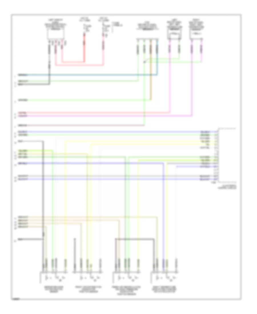
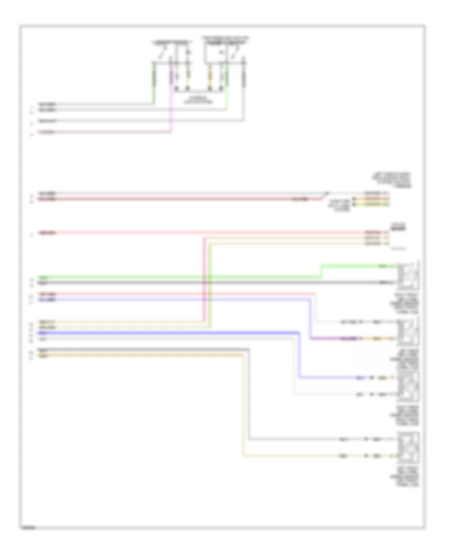
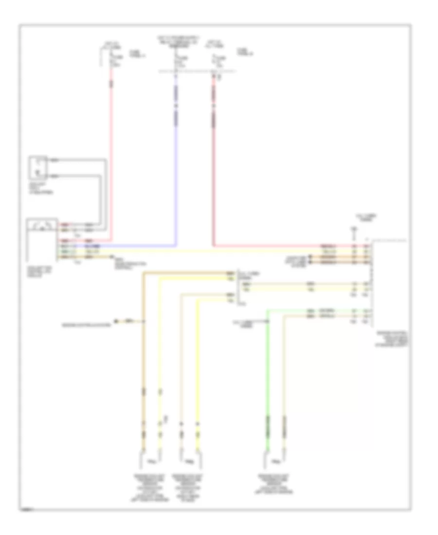
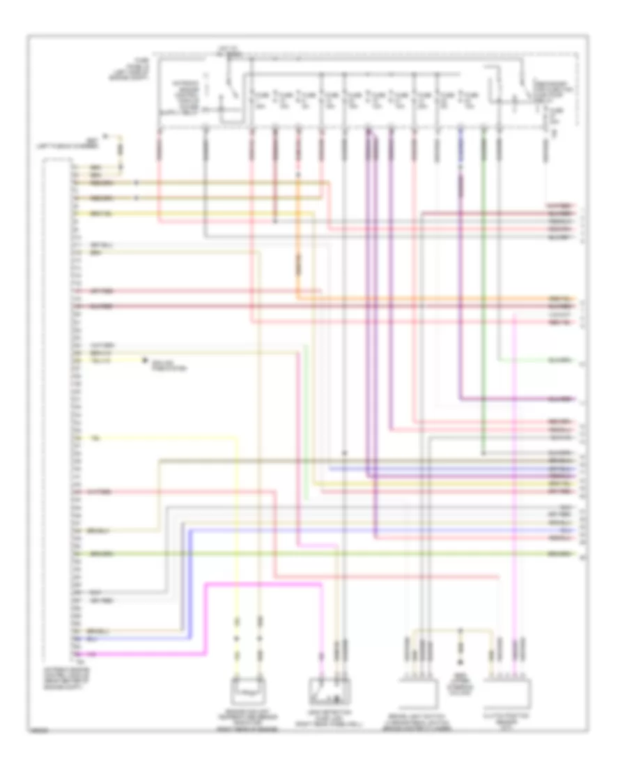
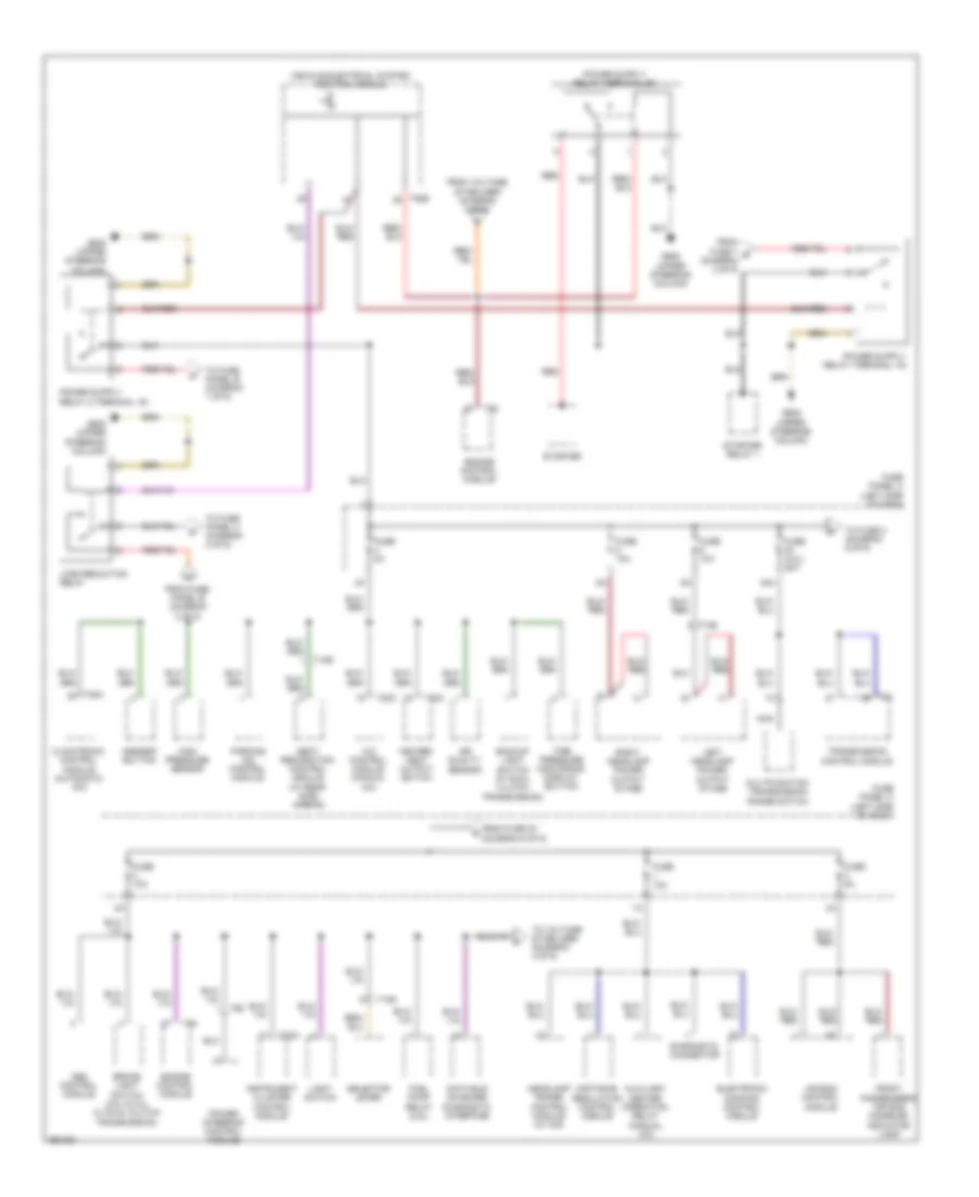
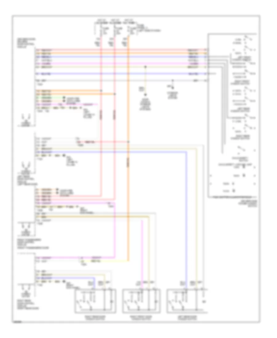
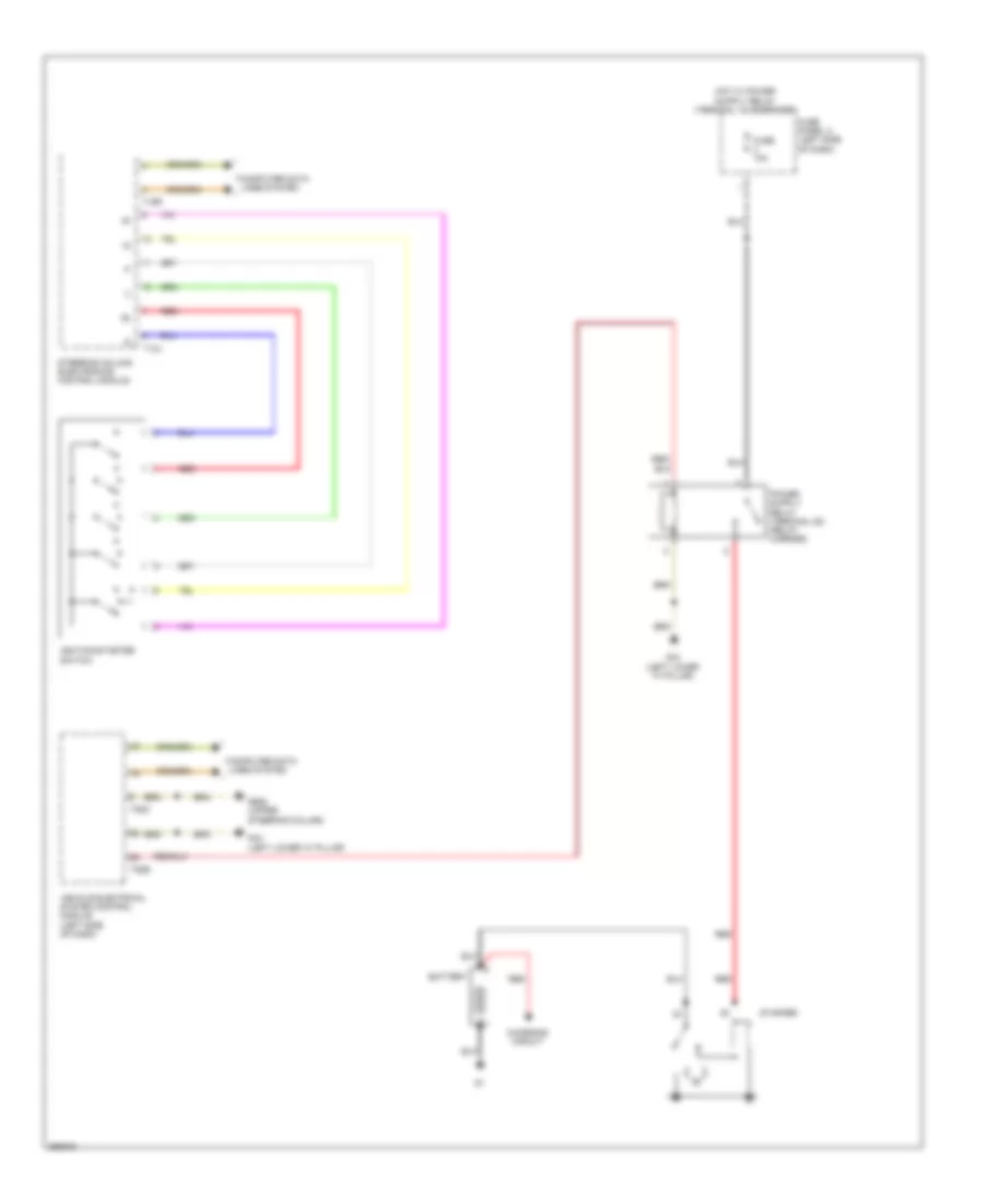
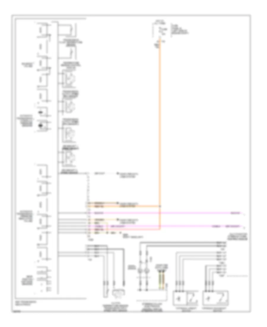
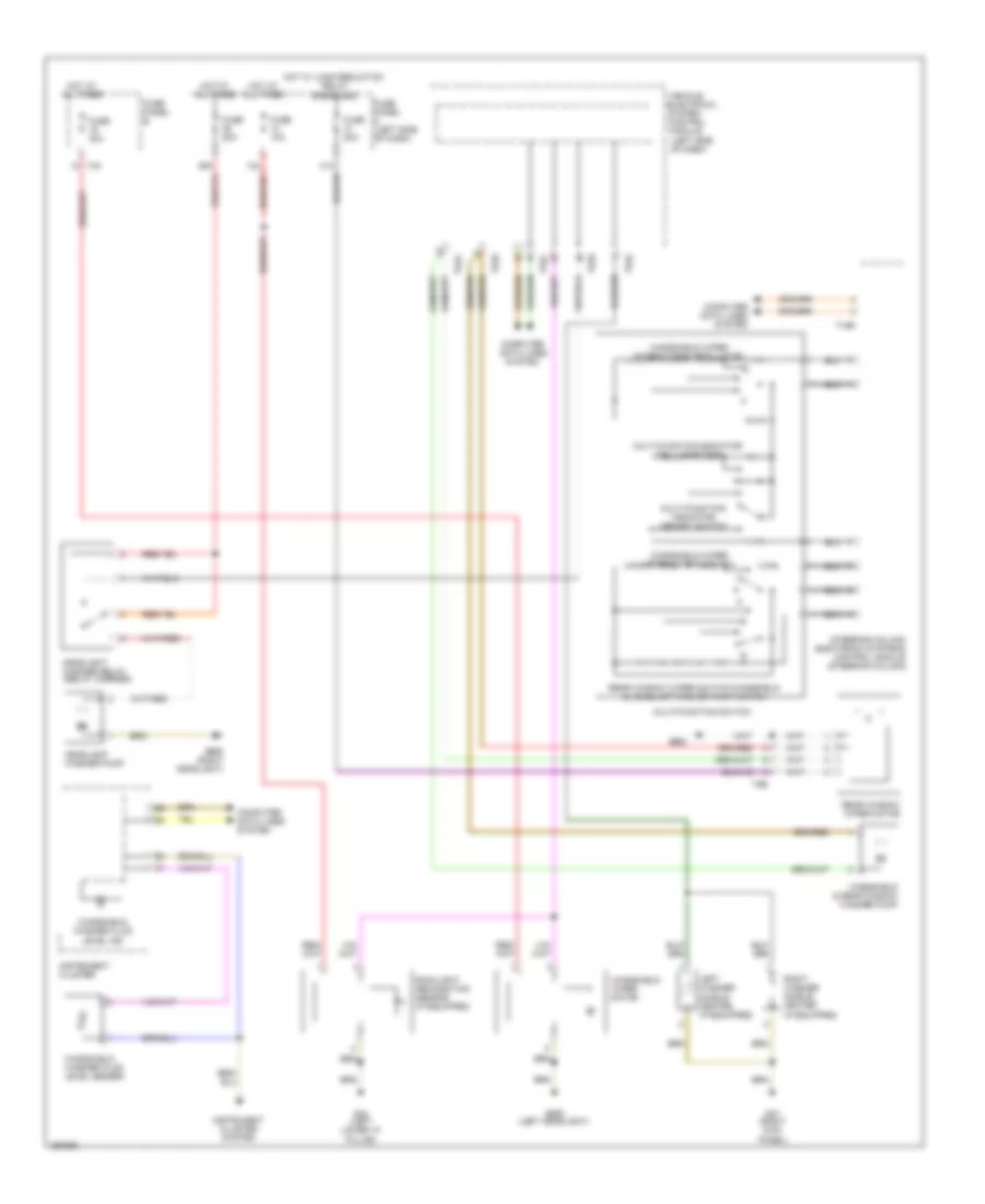
AIR CONDITIONING
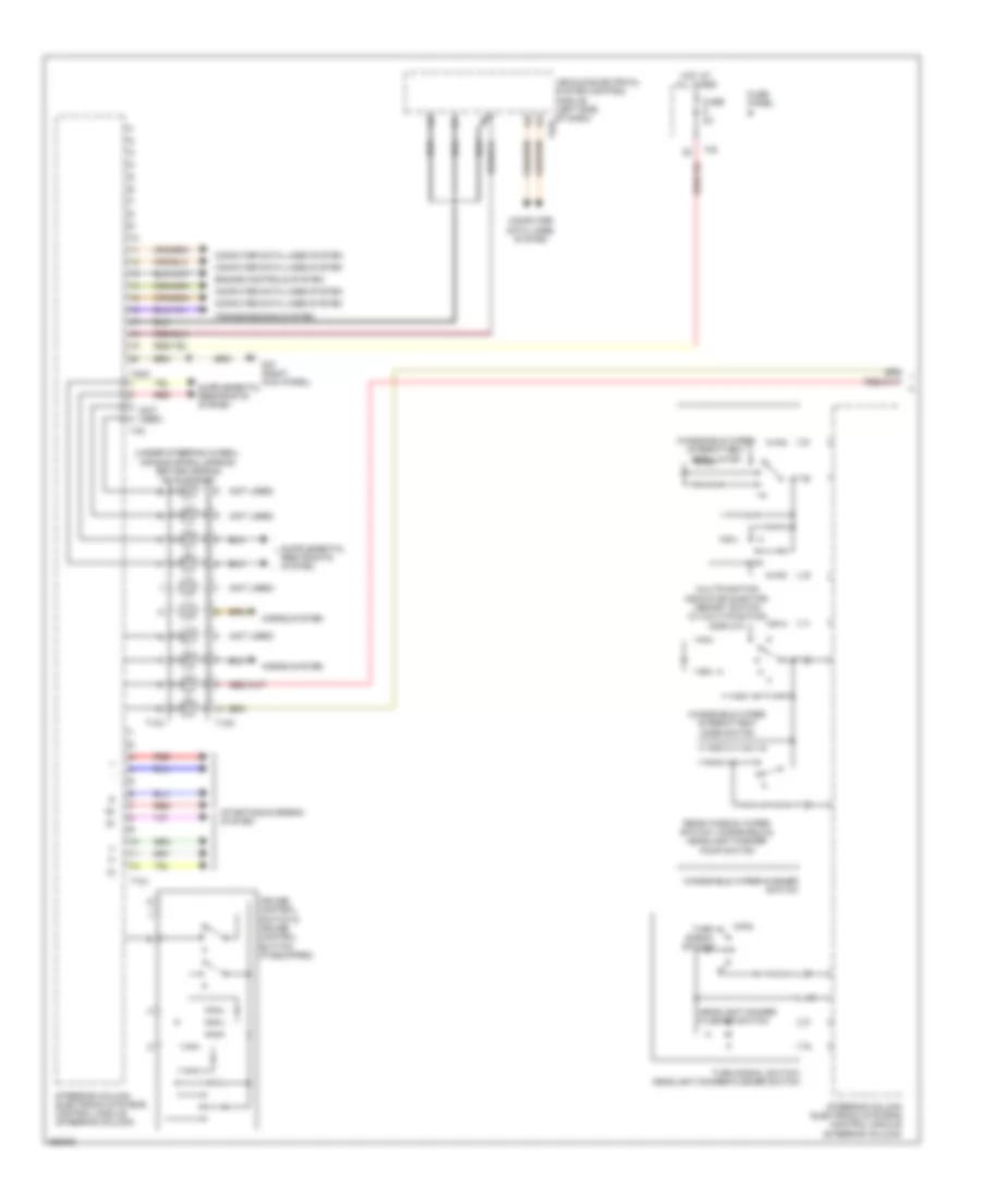
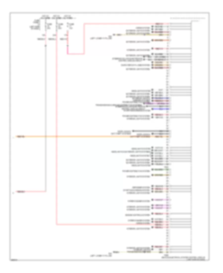
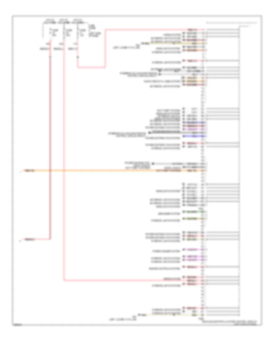
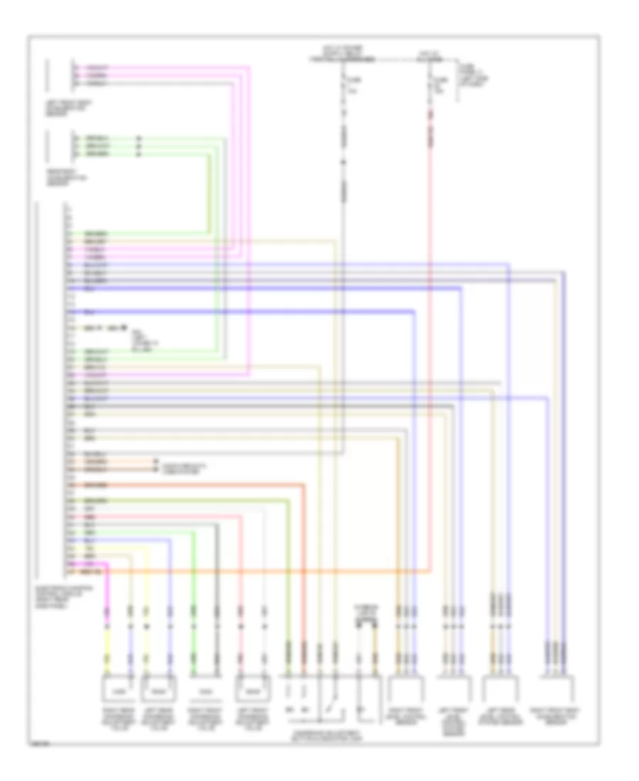
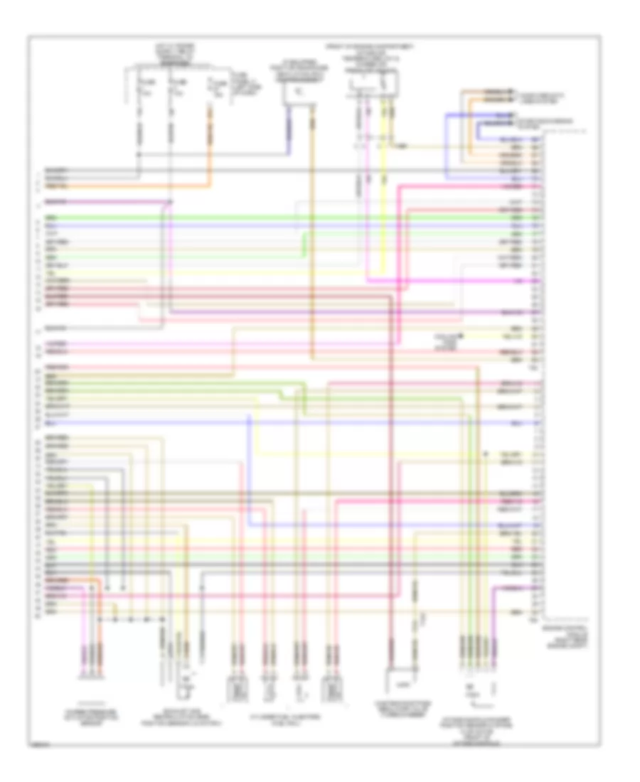
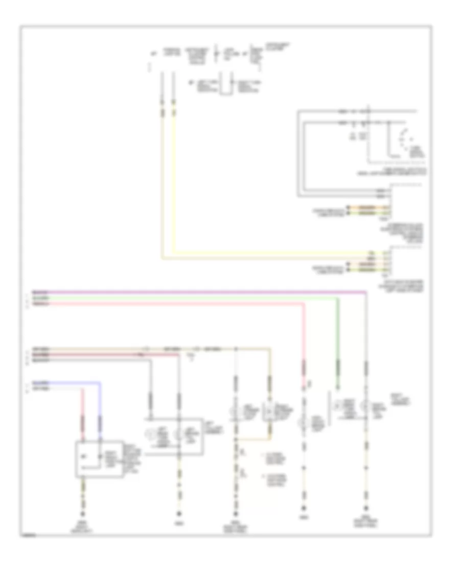
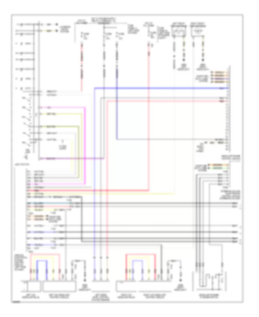
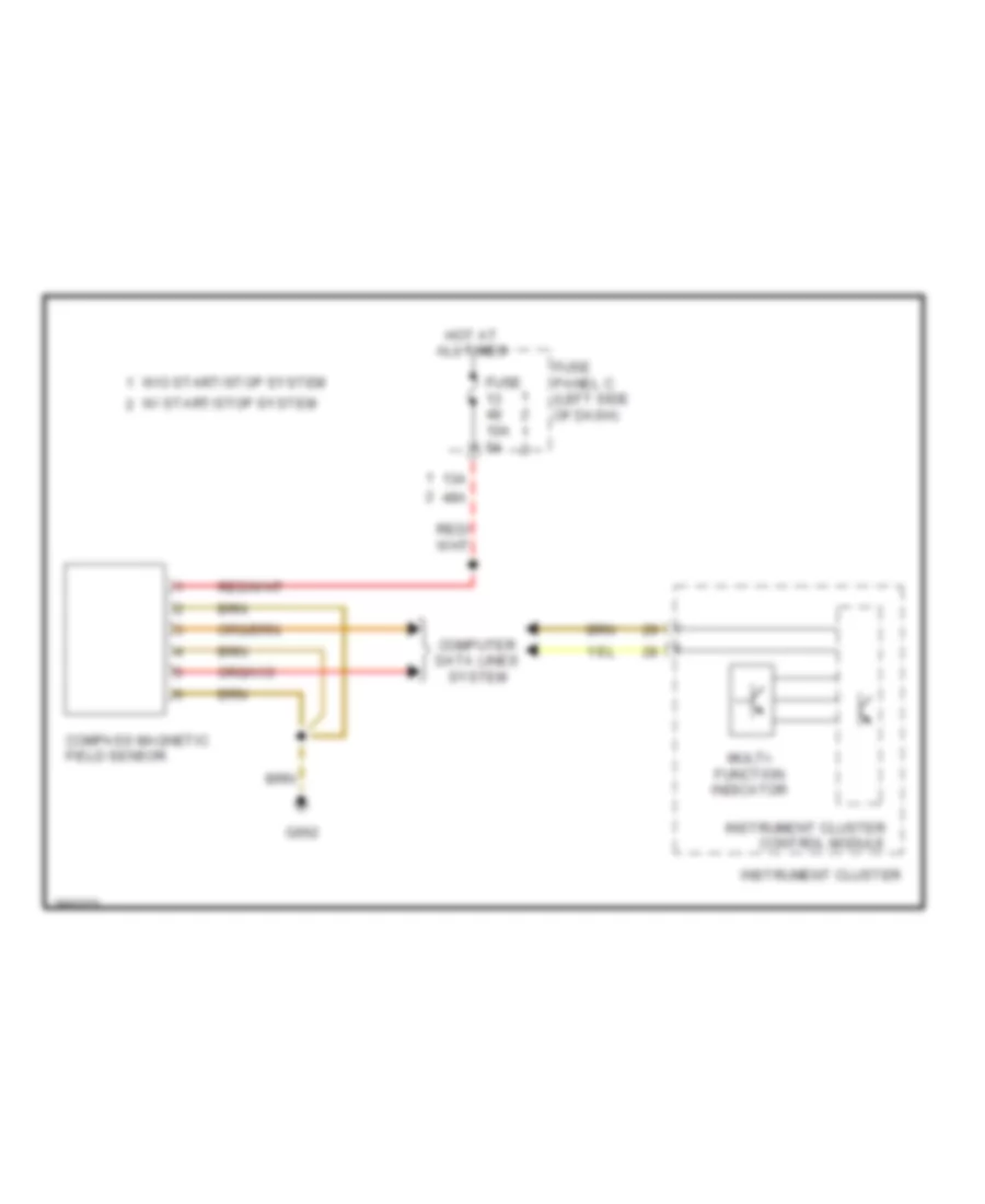
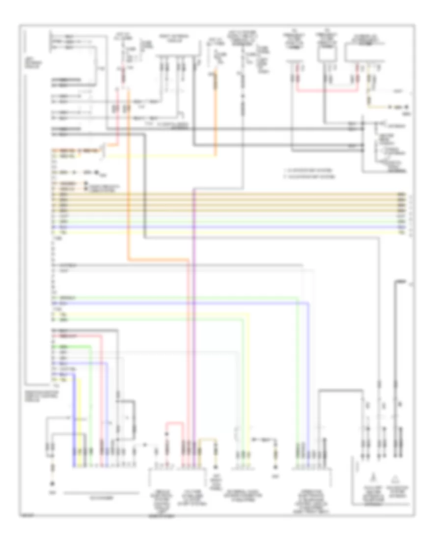
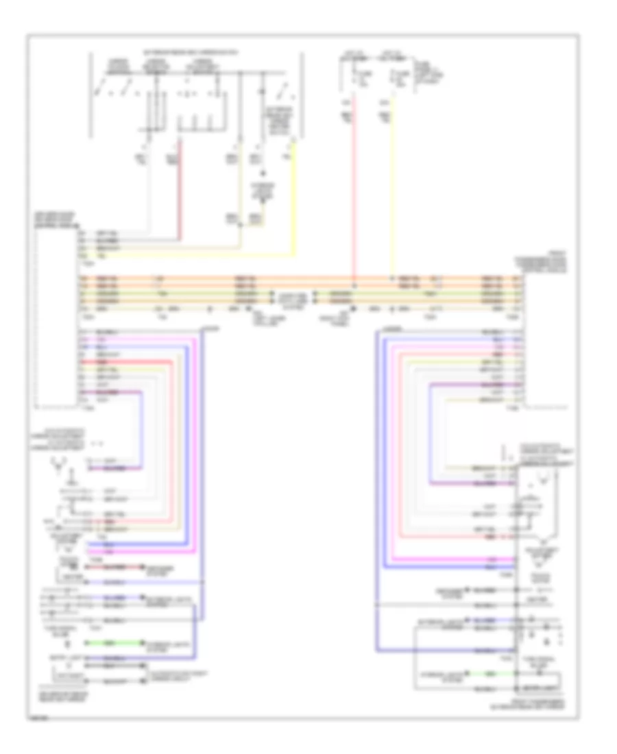
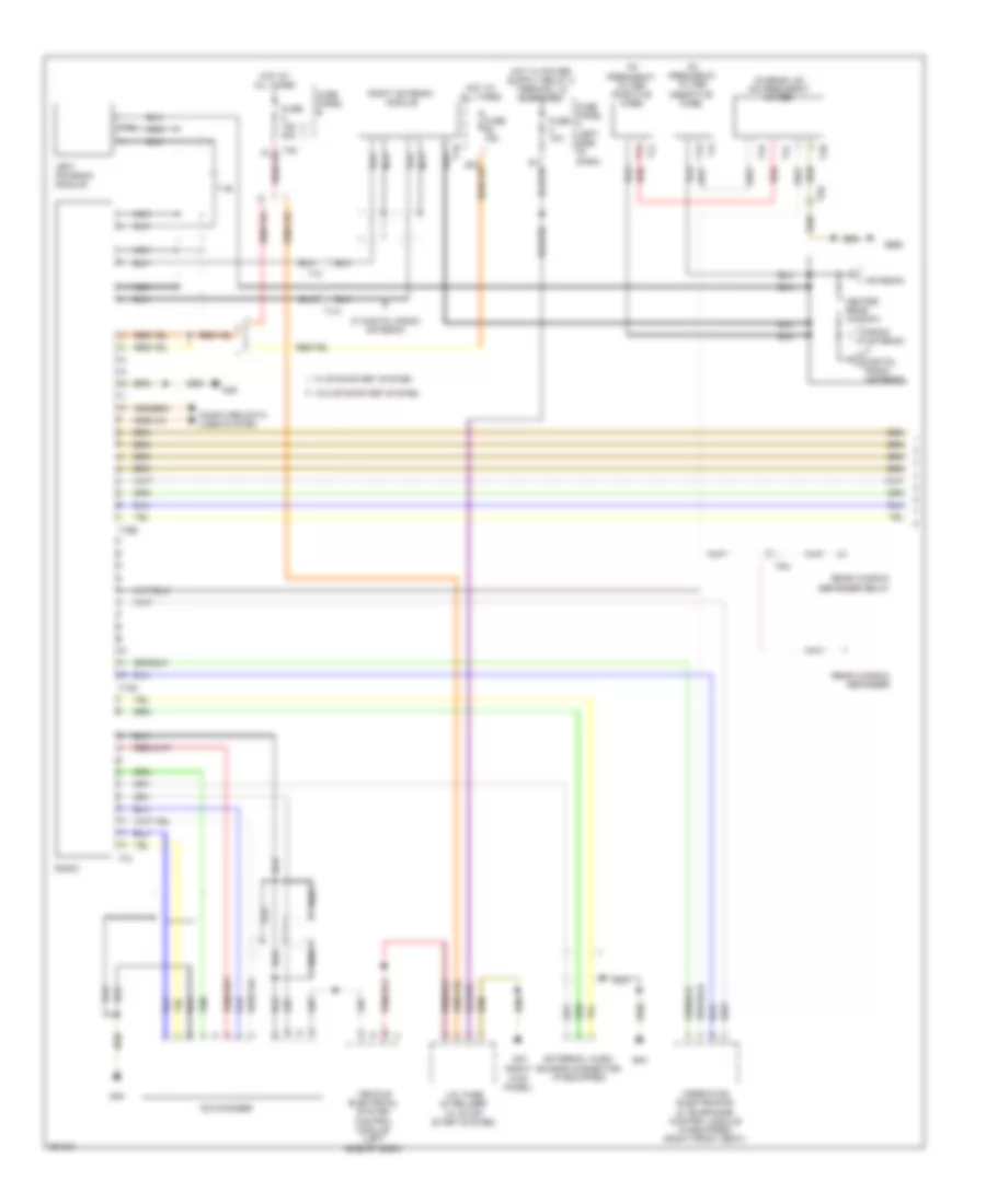
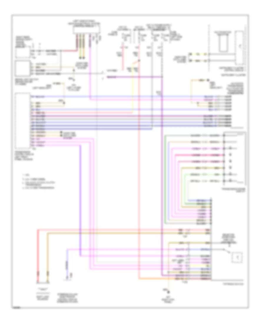
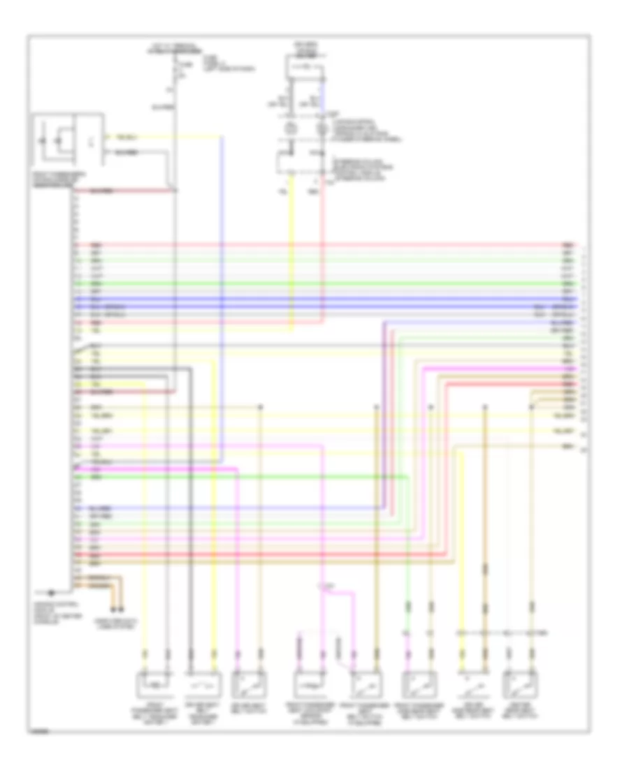
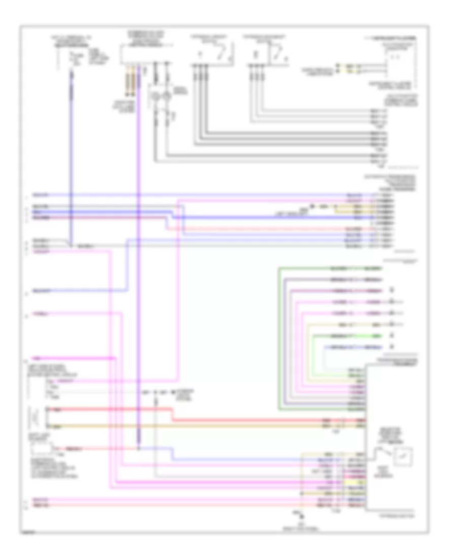
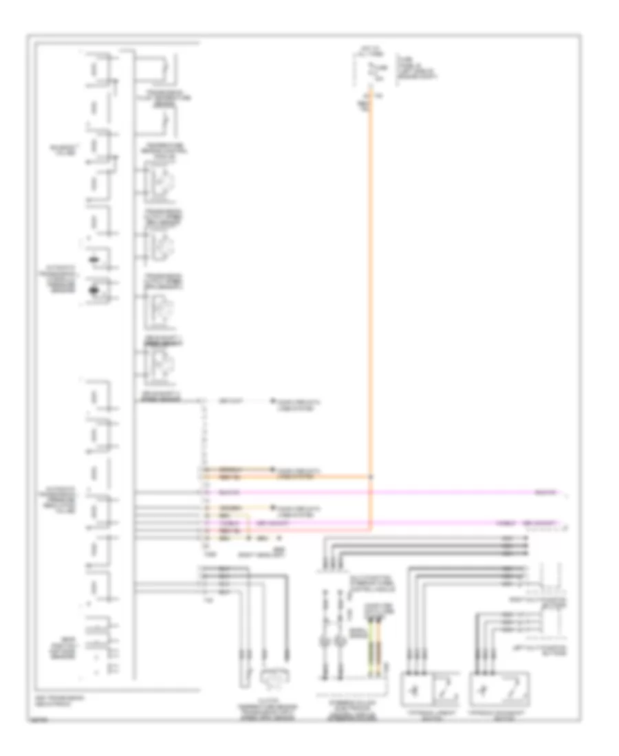
Automatic A/C Wiring Diagram (1 of 3) for Volkswagen Golf TDI 2010
 https://portal-diagnostov.com/license.html
Automotive Electricians Portal FZCO
Automotive Electricians Portal FZCO
https://portal-diagnostov.com/license.html
https://portal-diagnostov.com/license.html
Automotive Electricians Portal FZCO
Automotive Electricians Portal FZCO
List of elements for Automatic A/C Wiring Diagram (1 of 3) for Volkswagen Golf TDI 2010:
- (front of engine compt) high pressure sensor
- (rear of engine compt) air quality sensor
- 14a
- 22a
- A/c compressor regulator valve (rear of a/c compressor)
- Climatronic control module
- Computer data lines system
- Evaporator temperature sensor (center of hvac unit)
- Fresh air blower control module (fresh air blower motor)
- Fuse 10a
- Fuse 40a
- Fuse 5a
- Fuse panel c (left side of dash)
- G47 (right kick panel)
- G602 (left front kick panel)
- G605 (upper steering column)
- G655 (left headlight)
- Hot at all times
- Left footwell vent temperature sensor (left side of hvac unit)
- Left temperature door potentiometer/ actuator & motor
- Right footwell vent temperature sensor (center of hvac unit)
- Seats system
- T10k
- T16c
- T20c
- T4t
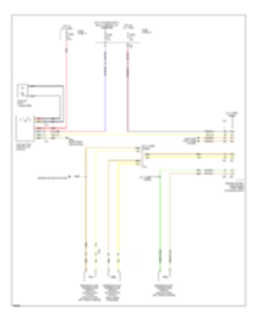
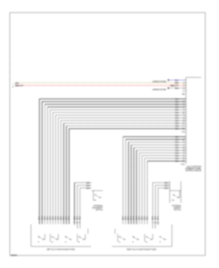
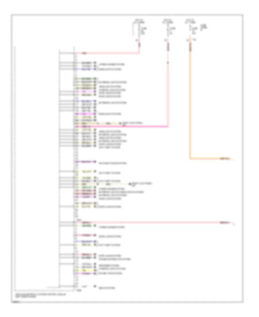
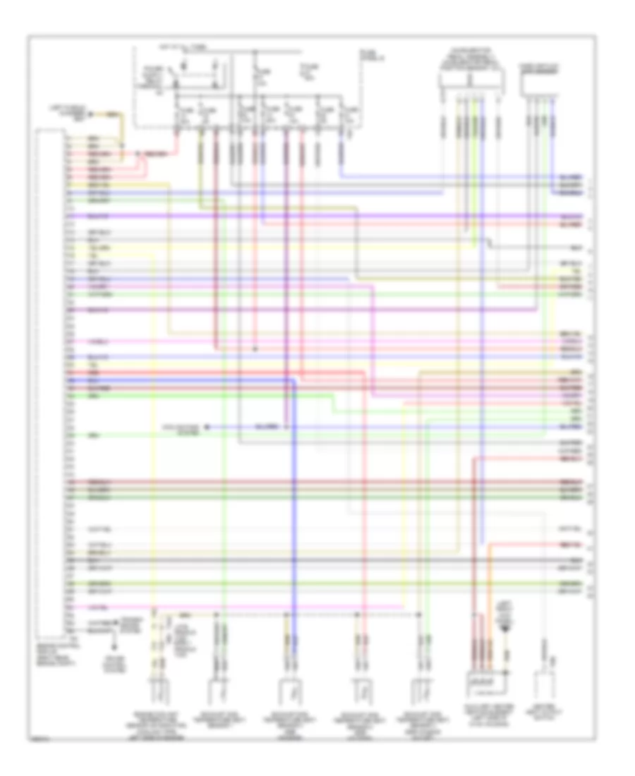
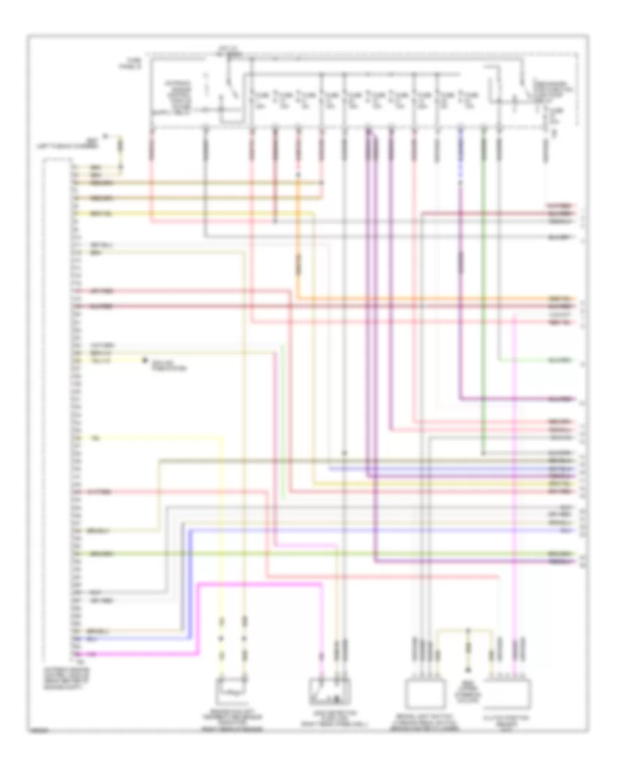
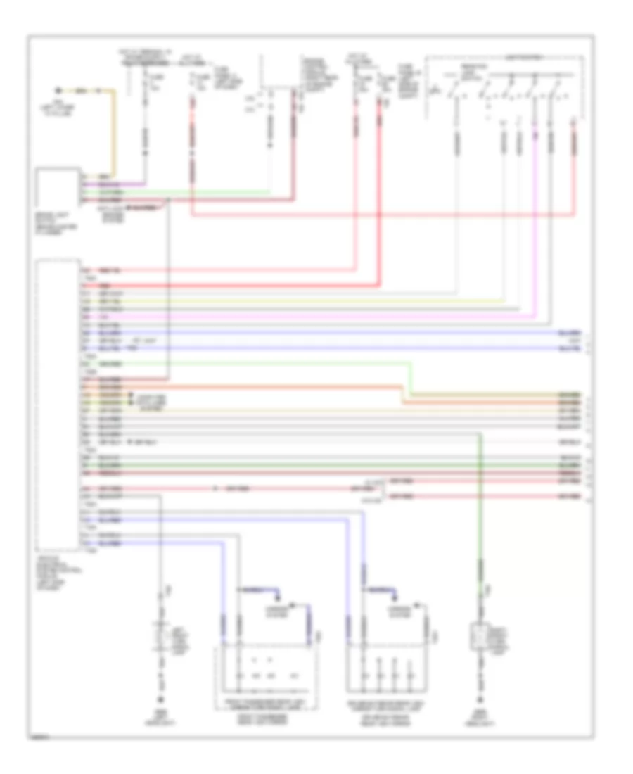
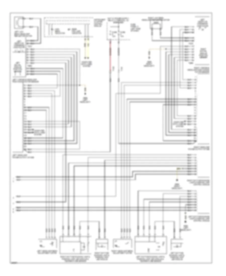
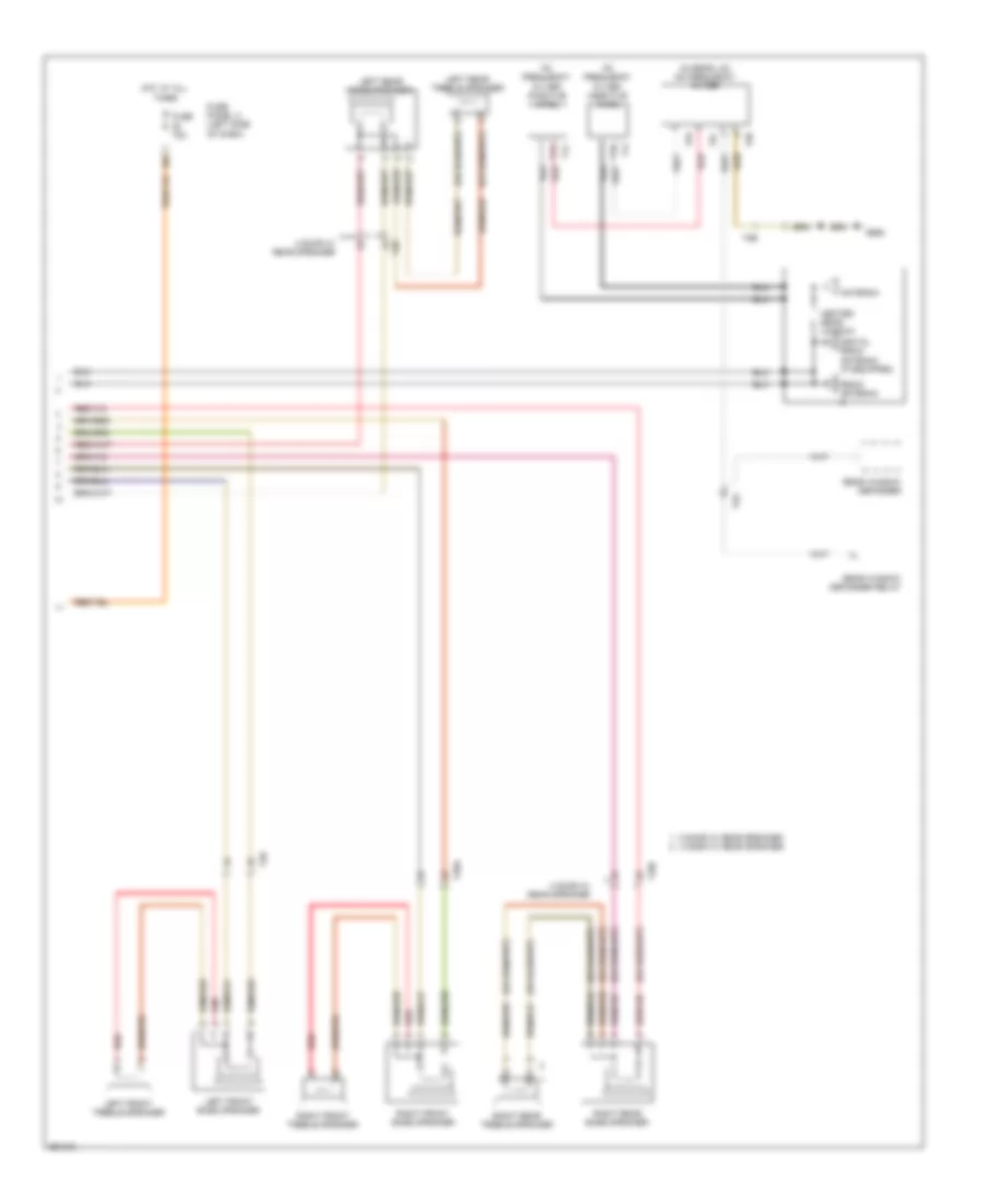
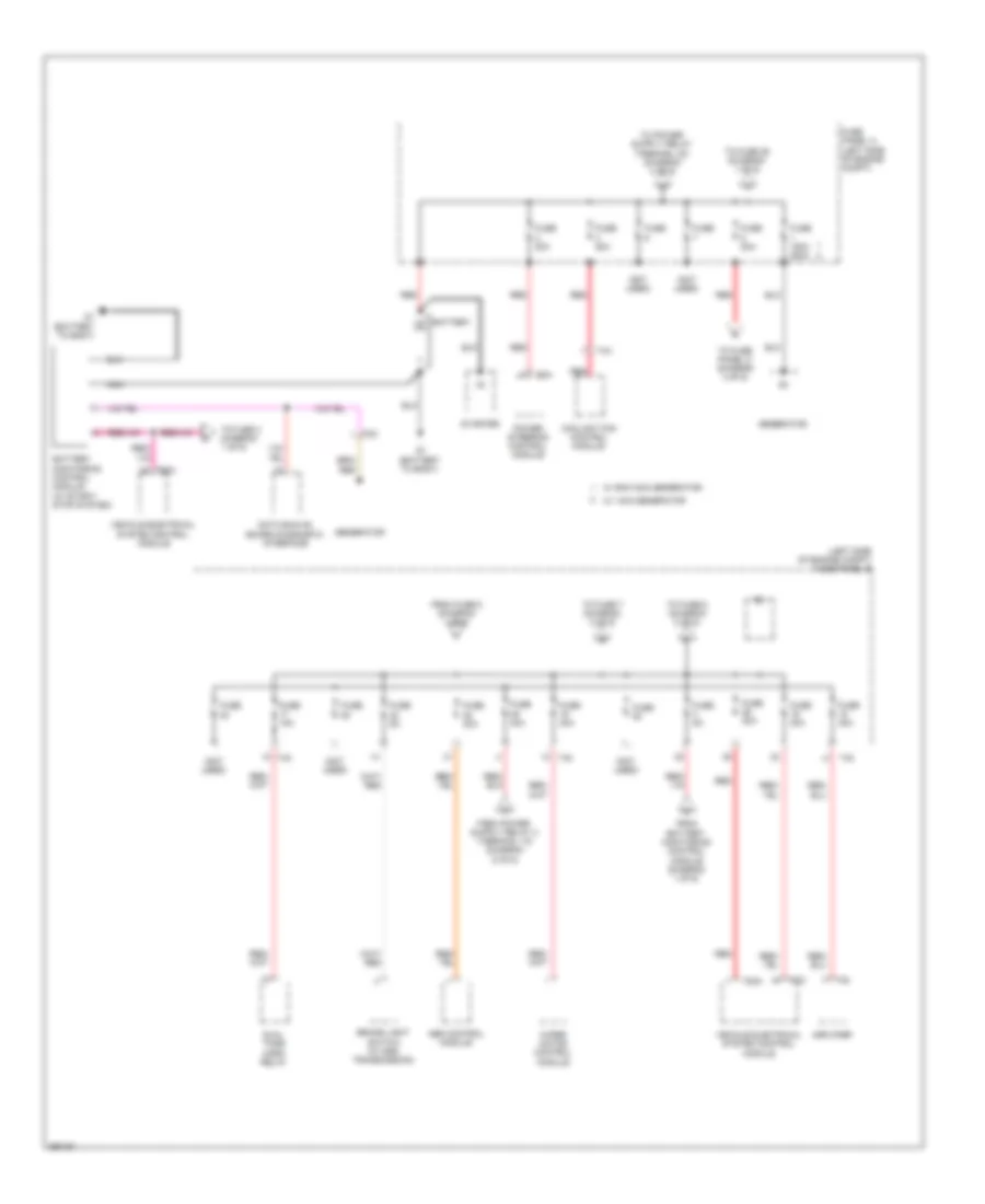
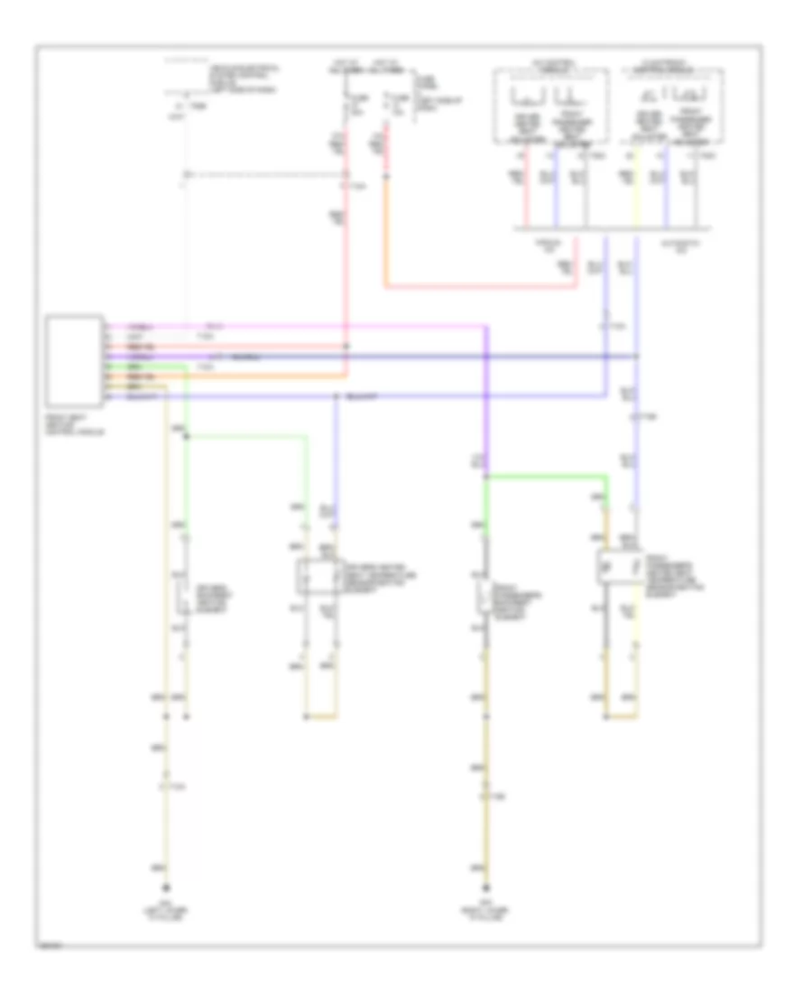
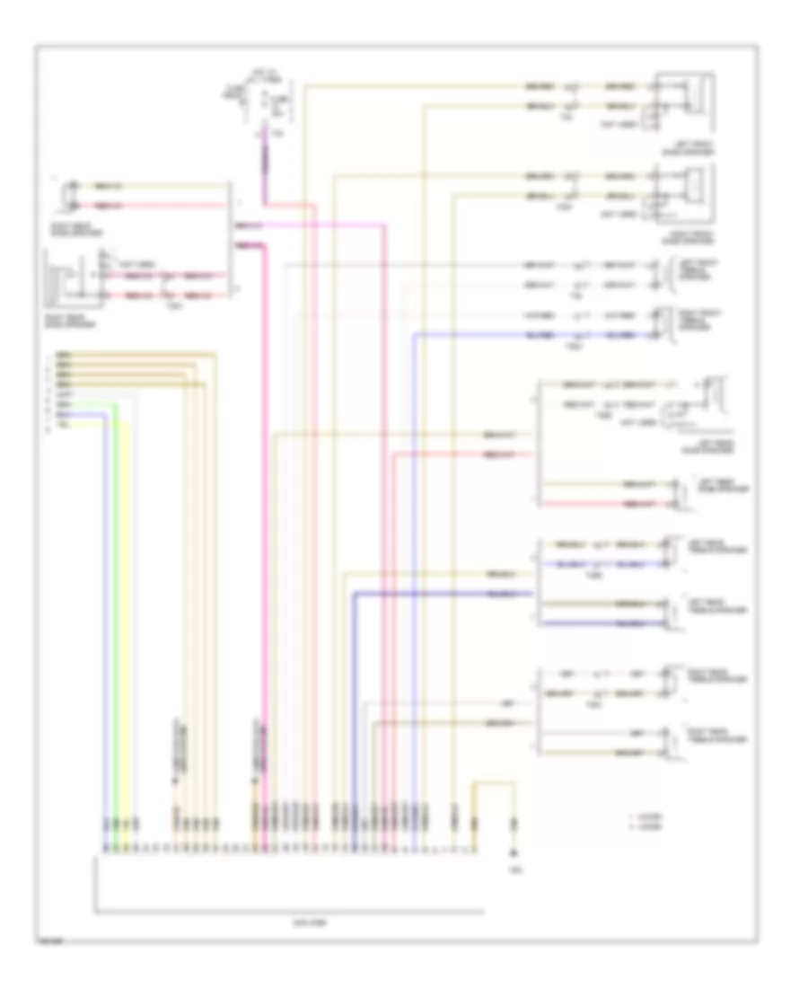
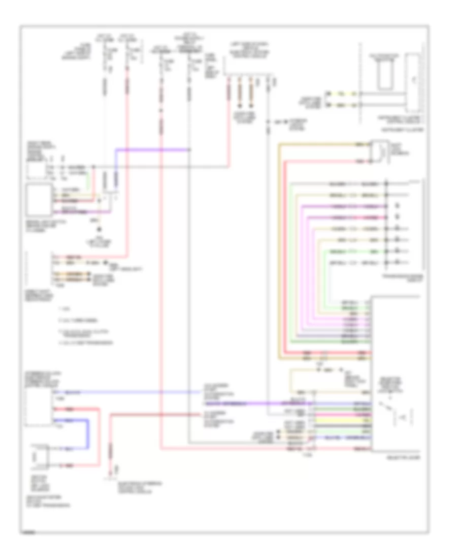
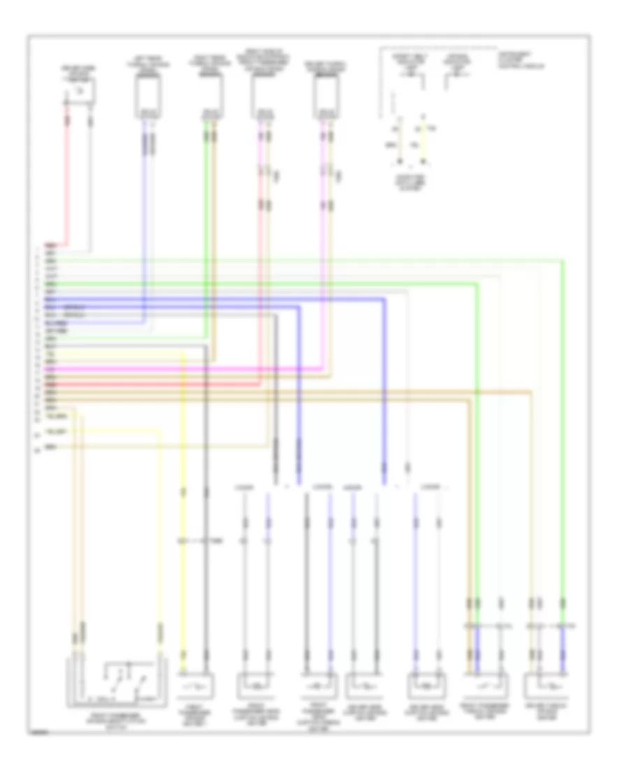
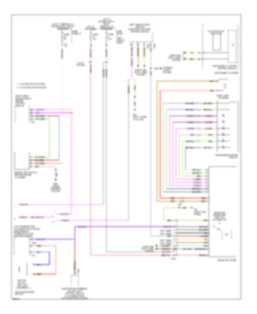
Automatic A/C Wiring Diagram (2 of 3) for Volkswagen Golf TDI 2010
List of elements for Automatic A/C Wiring Diagram (2 of 3) for Volkswagen Golf TDI 2010:
- (left end of dash) left vent temperature sensor
- (left side of dash) vehicle electrical system control module
- (right end of dash) right vent temperature sensor
- (top center of dash) sunlight photo sensor 2
- Climatronic control module
- Defroster door motor position sensor
- Fresh air/ recirculating air/ back pressure door motor position sensor
- Front air distribution door motor position sensor
- Fuse 30a
- Fuse panel b
- Hot at all times
- Red
- Right temperature door potentiometer/ actuator & motor
- T16d
- T40
- T52a
- T52b
- T52c
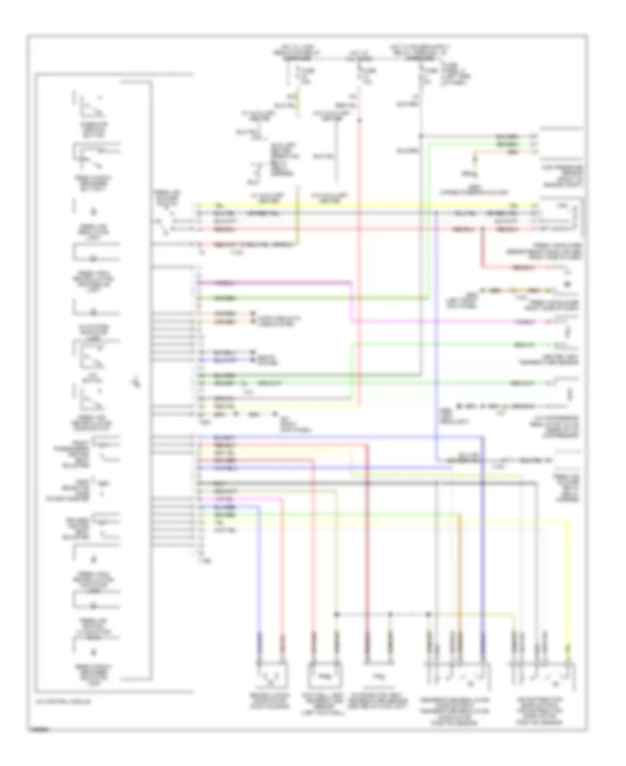
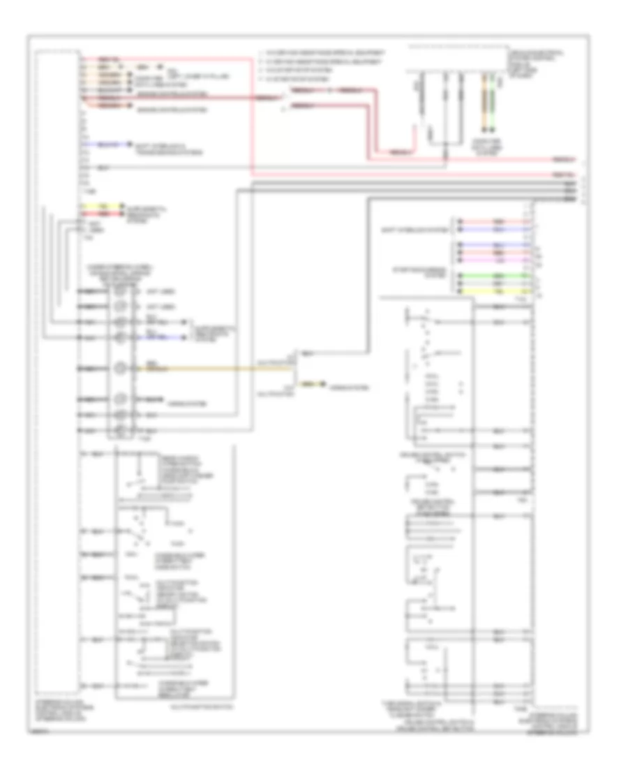
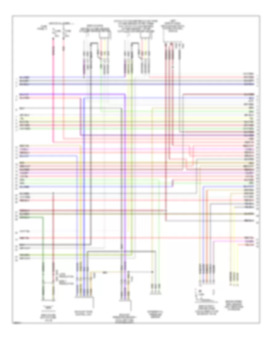
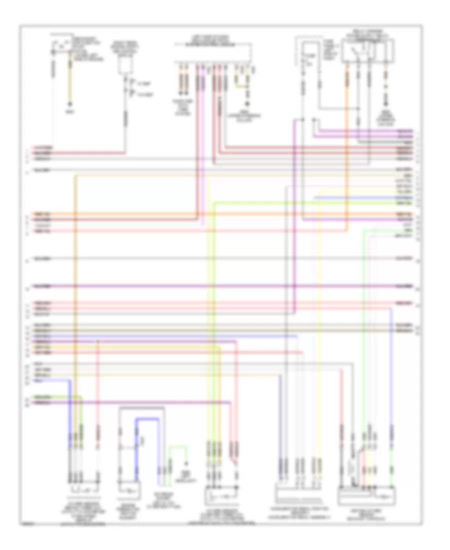
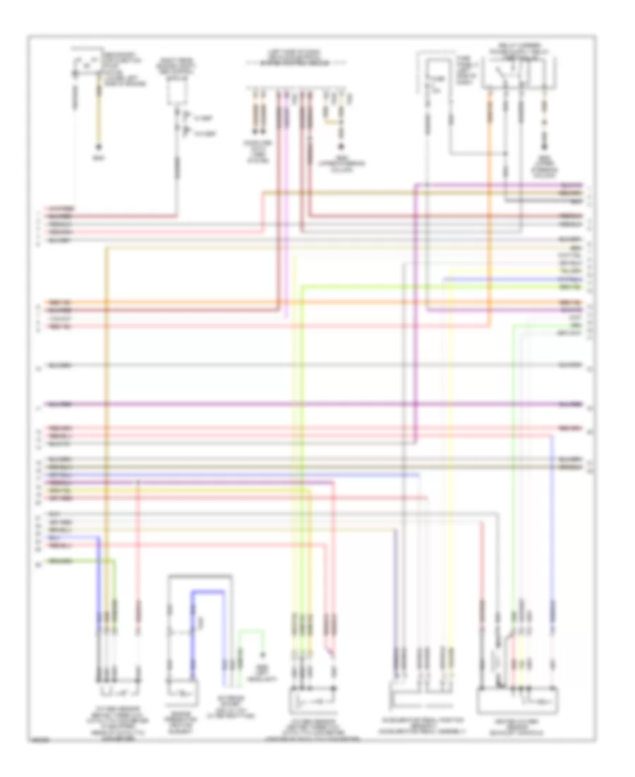
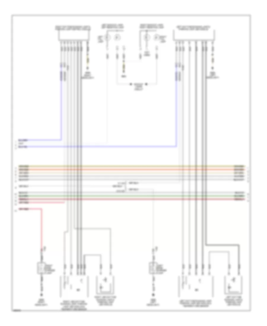
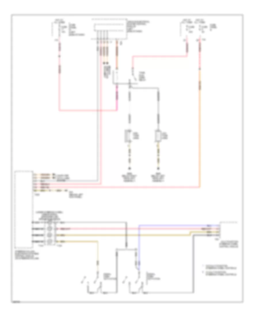
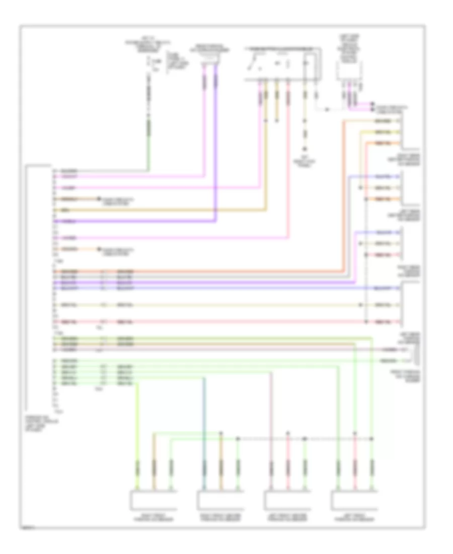
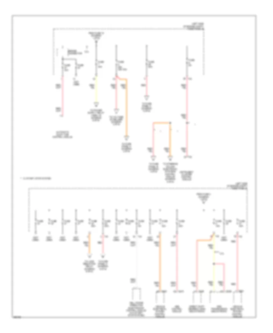
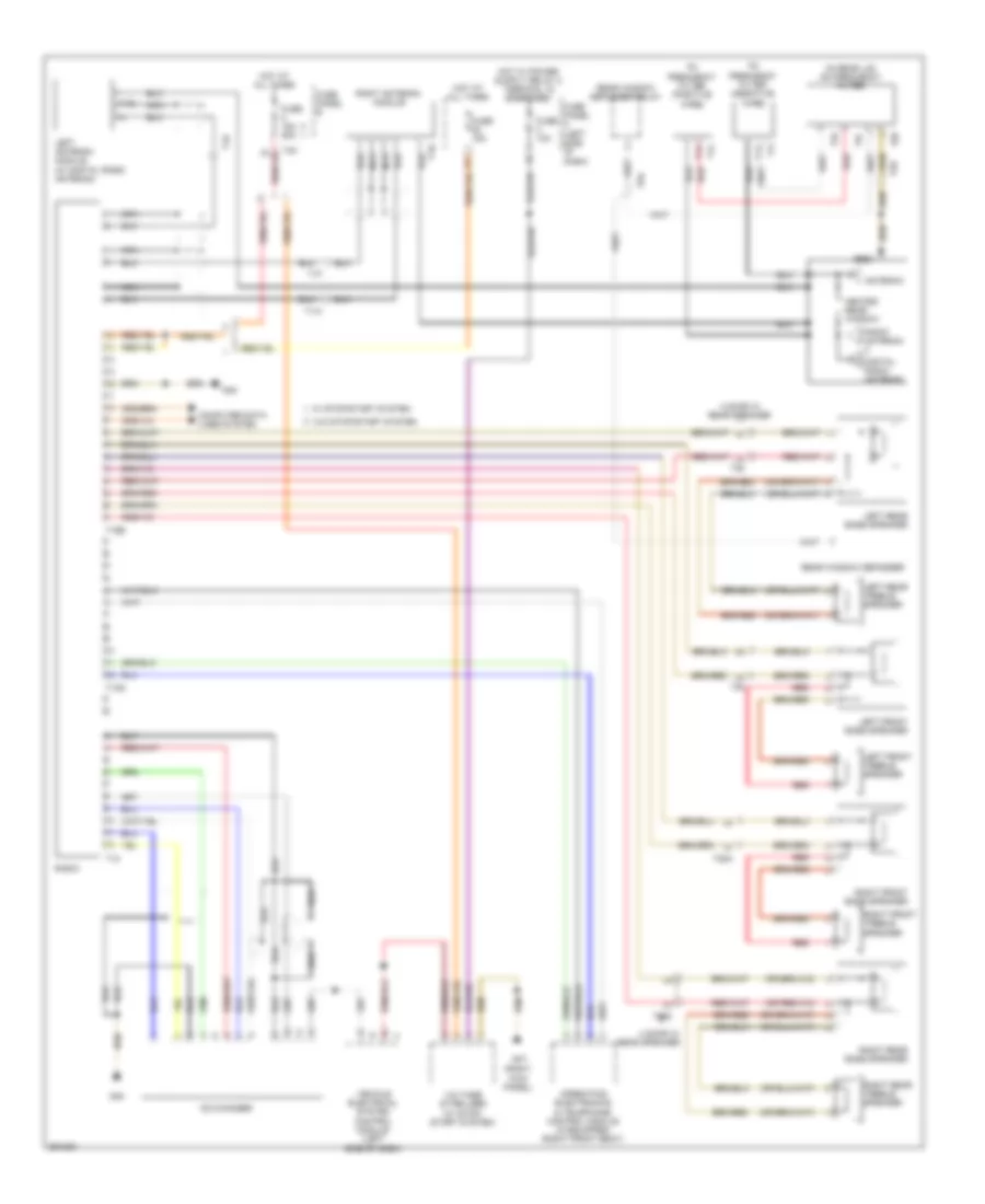
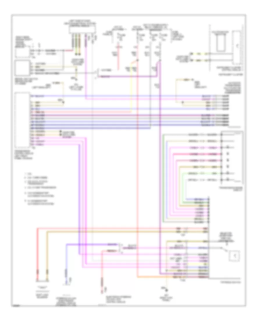
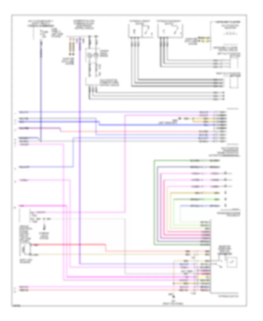
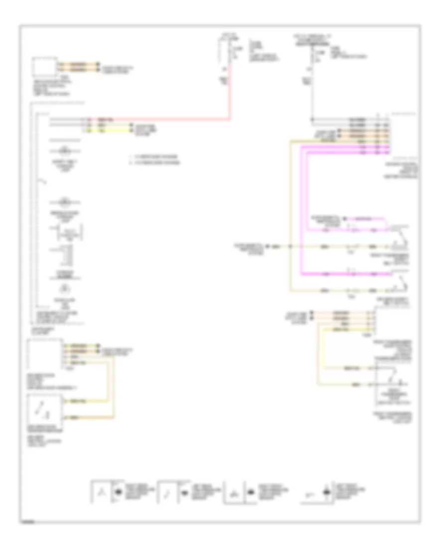
Automatic A/C Wiring Diagram (3 of 3) for Volkswagen Golf TDI 2010
List of elements for Automatic A/C Wiring Diagram (3 of 3) for Volkswagen Golf TDI 2010:
- (right rear of engine)
- 2.0l turbo diesel
- 2.5l
- Computer data lines system
- Coolant fan 2 (if equipped)
- Coolant fan control (fc) module
- Engine control module (ecm) (right rear of engine compt)
- Engine controls system
- Engine coolant temperature sensor (coolant pipe, left side of engine)
- Engine coolant temperature sensor (on radiator outlet)
- Engine coolant temperature sensor (on radiator outlet) (coolant pipe, left side of engine)
- Fuse 10a
- Fuse 50a
- Fuse panel a
- Fuse panel b
- G642 (electronic fan control)
- Hot at all times
- Nca
- Red
- T10l
- T2v
- T40
- T4x
- T60
- T94
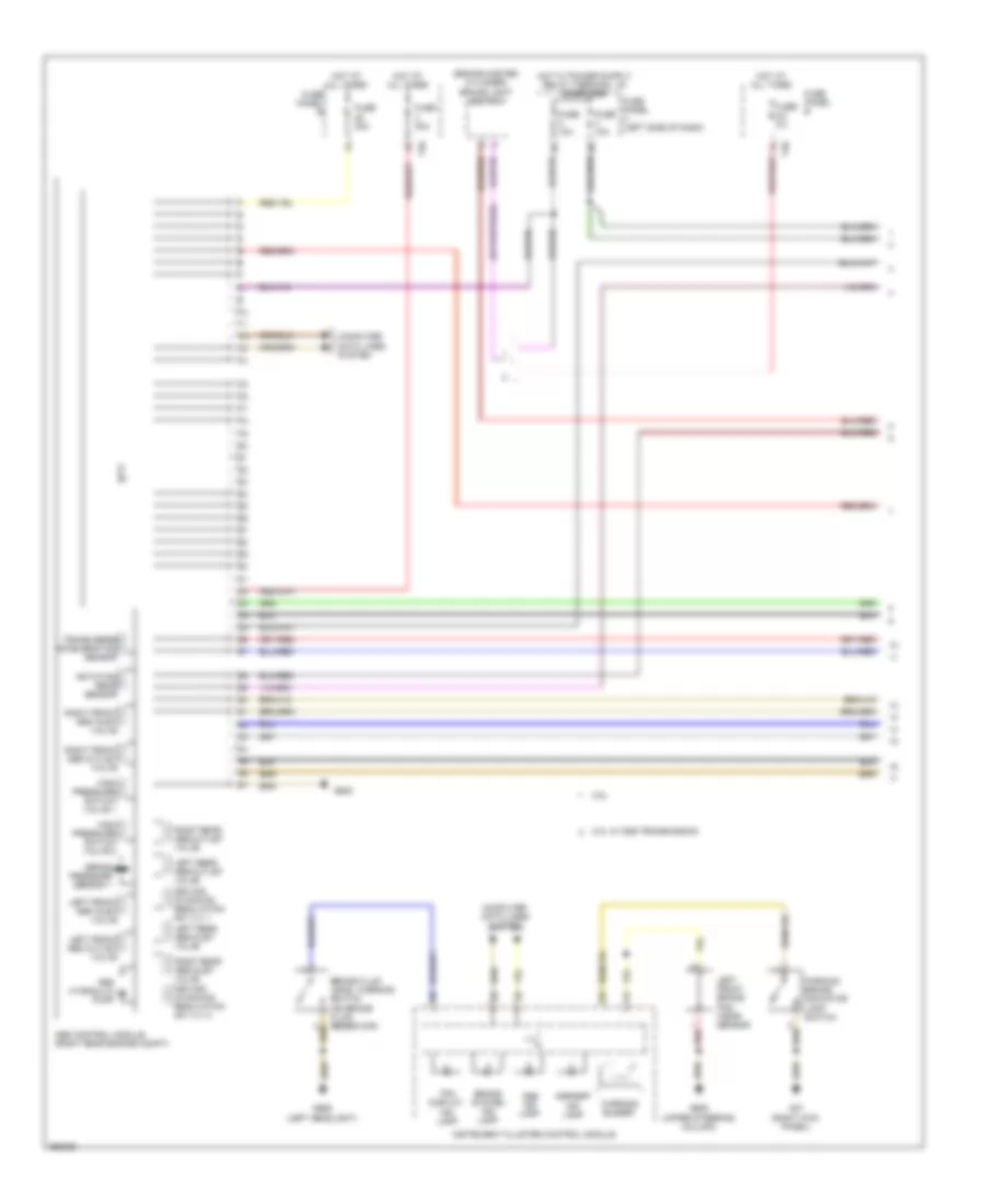
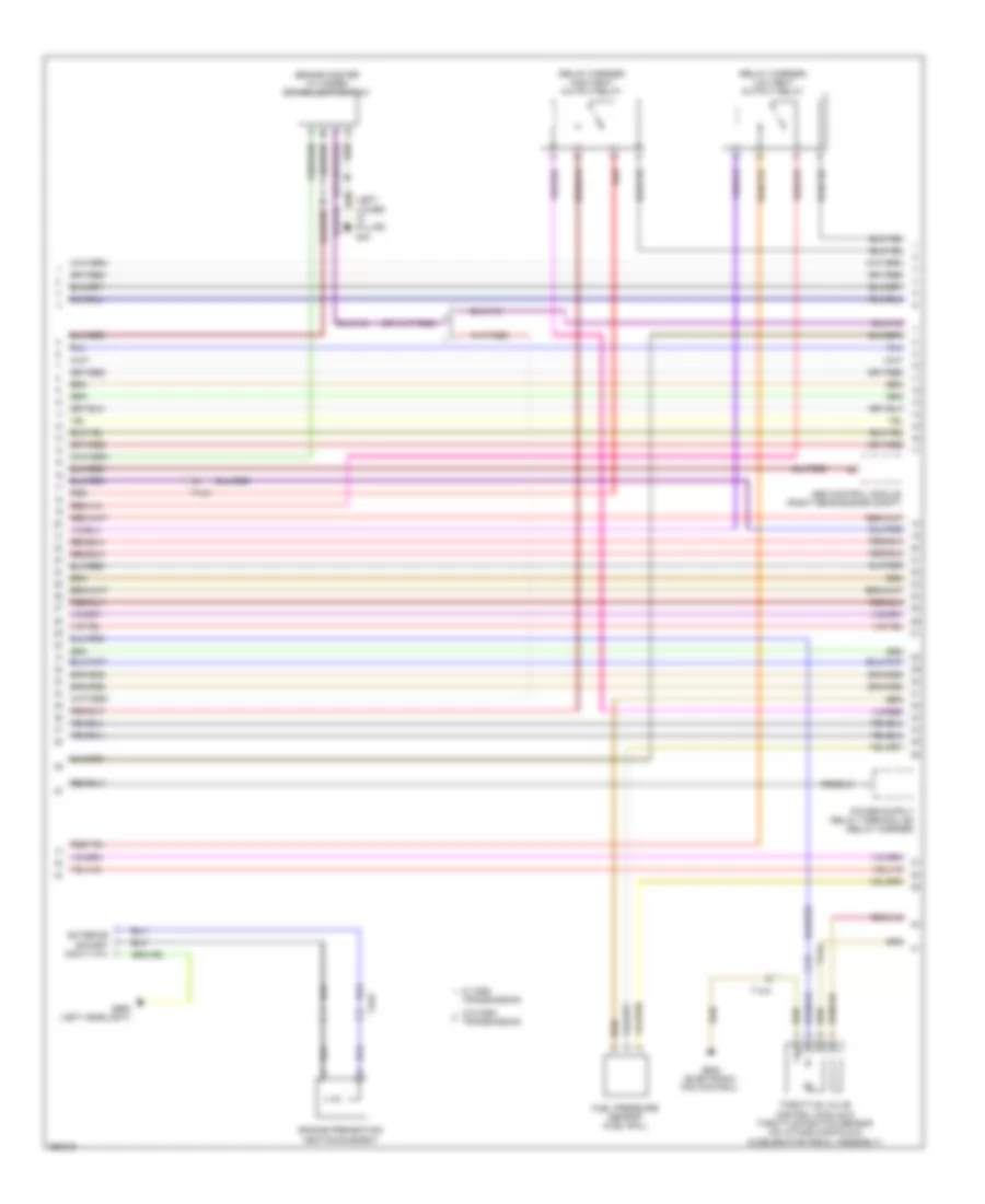
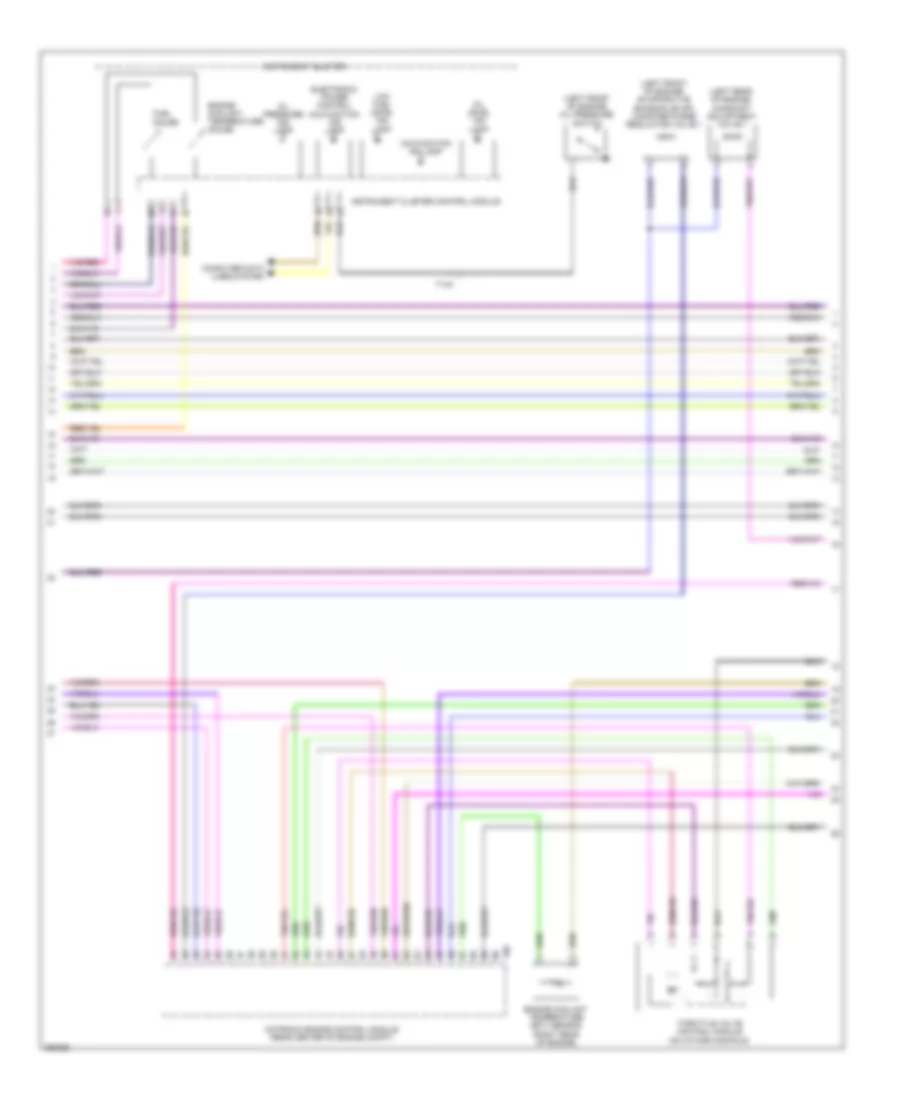
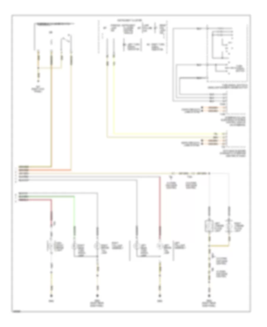
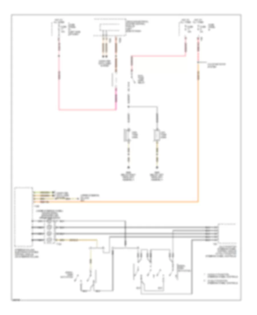
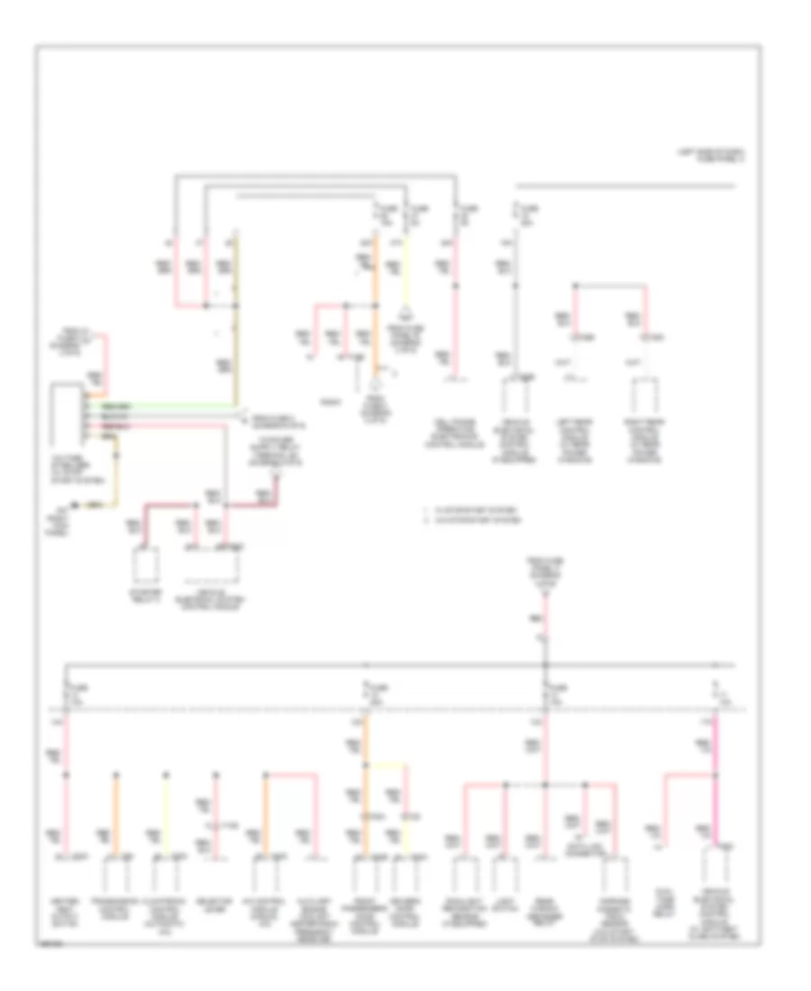
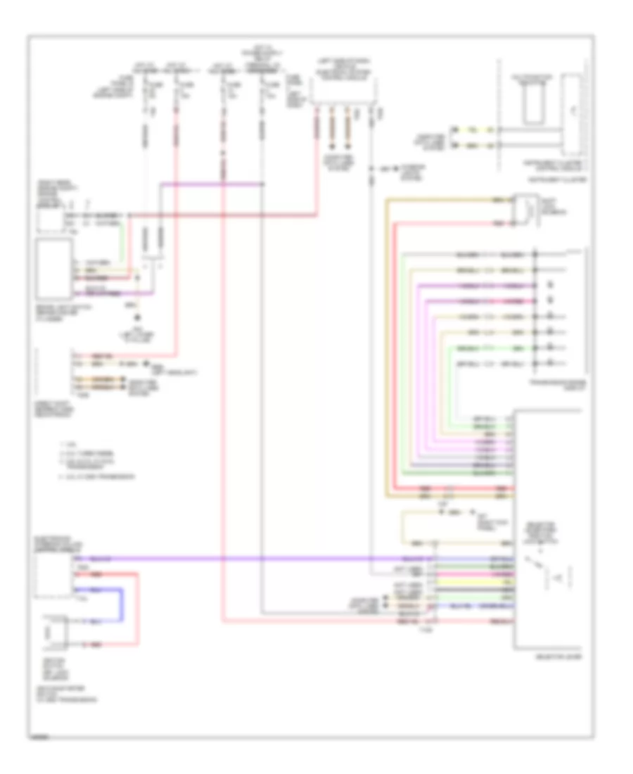
Auxiliary Heater Wiring Diagram for Volkswagen Golf TDI 2010
List of elements for Auxiliary Heater Wiring Diagram for Volkswagen Golf TDI 2010:
- (2.0l turbo diesel)
- (left headlight) g655
- (right rear side panel) g682
- 14a
- 25a
- 40a
- A/c control module (manual a/c)
- Antenna splitter
- Auxiliary engine coolant heating rf receiver (right rear side panel)
- Auxiliary heater antenna
- Auxiliary heater control module
- Auxiliary heater operation relay (manual a/c) (relay carrier)
- Climatronic control module (automatic a/c)
- Combustion air blower
- Computer data lines system
- Early production
- Element
- Fresh air blower relay (manual a/c)
- Fuel cut off valve
- Fuel preheating
- Fuse 10a
- Fuse 25a
- Fuse 30a 20a
- Fuse 40a
- Fuse panel b
- Fuse panel c (left side of dash)
- G44 (left lower "a" pillar)
- G655 (left headlight)
- Glow plug w/ flame monitoring
- Heater coolant shut-off valve (if equipped)
- Hot at all times
- Hot w/ load reduction relay energized
- Immediate heating button
- Late production
- Manual a/c circuit
- Metering pump
- Nca
- Overheat sensor
- Recirculation pump
- Red
- T10k
- T20c
- T2by
- T2g
- T2k
- T2m
- T3z
- T40
- T4bm
- T8f
- T8o
- Temperature sensor
Manual A/C Wiring Diagram (1 of 2) for Volkswagen Golf TDI 2010
List of elements for Manual A/C Wiring Diagram (1 of 2) for Volkswagen Golf TDI 2010:
- 14a
- 40a
- A/c compressor regulator valve (rear of a/c compressor)
- A/c control module
- A/c switch
- A/c system indicator lamp
- Air distribution door motor & air distribution door motor position sensor
- Auxiliary heater operation relay (relay carrier)
- Center vent temperature sensor
- Computer data lines system
- Driver's heated seat adjuster
- Evaporator vent temperature sensor (center of hvac unit)
- Footwell vent temperature sensor (left footwell)
- Fresh air & recirculating air mode ind light
- Fresh air & recirculating indicator lamp
- Fresh air blower (right side of dash)
- Fresh air blower relay (relay carrier)
- Fresh air blower series resistance (w/fuse) (right side of dash)
- Fresh air blower switch
- Fresh air control illumination bulb
- Fresh air regulator light
- Fresh air/ recirculating door switch
- Front passenger's heated seat adjuster
- Fuse 10a
- Fuse 40a
- Fuse 5a
- Fuse panel c (left side of dash)
- G47 (right kick panel)
- G602 (left front kick panel)
- G605 (upper steering column)
- G655 (left headlight)
- High pressure sensor (front of engine compt)
- Hot at all times
- Hot w/ load reduction relay energized
- Immediate heating button
- Rear window defogger button 7
- Rear window defogger indicator lamp
- Recirculation door motor (hvac housing)
- Seats system
- T10k
- T16e
- T20c
- T4t
- Temp selector knob potentiometer
- Temperature regulator door motor & temperature regulator door motor position sensor
- W/ auxiliary heater
- W/o auxiliary heater
Manual A/C Wiring Diagram (2 of 2) for Volkswagen Golf TDI 2010
List of elements for Manual A/C Wiring Diagram (2 of 2) for Volkswagen Golf TDI 2010:
- (right rear of eng)
- 2.0l turbo diesel
- 2.5l
- Computer data lines system
- Coolant fan 2 (if equipped)
- Coolant fan control (fc) module
- Engine control module (ecm) (right rear of engine compt)
- Engine controls system
- Engine coolant temperature sensor (coolant pipe, left side of engine)
- Engine coolant temperature sensor (on radiator outlet)
- Engine coolant temperature sensor (on radiator outlet) (coolant pipe, left side of engine)
- Fuse 10a
- Fuse 50a
- Fuse panel a
- Fuse panel b
- G642 (electronic fan control)
- Hot at all times
- Nca
- Red
- T10l
- T2v
- T40
- T4x
- T60
- T94
ANTI-LOCK BRAKES
Anti-lock Brakes Wiring Diagram, with ESP (1 of 2) for Volkswagen Golf TDI 2010
List of elements for Anti-lock Brakes Wiring Diagram, with ESP (1 of 2) for Volkswagen Golf TDI 2010:
- (brake master cylinder) brake light switch
- 2.0l w/ dsg transmission
- 2.5l
- Abs control module (right rear engine compt)
- Abs hydraulic pump
- Abs ind lamp
- Asr/esp ind lamp
- Brake fluid level warning switch (on brake fluid reservoir)
- Brake pressure sensor 1
- Brake system ind lamp
- Computer
- Computer data lines system
- Data lines system
- Driving dynamics regulation sw vlv 1
- Fuse 10a
- Fuse 30a
- Fuse 5a
- Fuse panel b
- Fuse panel c (left side of dash)
- G47 (right kick panel)
- G605 (upper steering column)
- G638
- G655 (left headlight)
- High pressure switch valve 1
- High pressure switch valve 2
- Hot at all times
- Instrument cluster control module
- Left front abs inlet valve
- Left front abs outlet valve
- Left front brake pad wear sensor
- Left rear abs inlet valve
- Left rear abs outlet valve
- Parking brake indicator lamp switch
- Red
- Right front abs inlet valve
- Right front abs outlet valve
- Right rear abs inlet valve driving dynamics regulation sw vlv 2
- Right rear abs outlet valve
- Rotation rear sensor
- T40
- Tpm display ind lamp
- Transverse acceleration sensor
- Warning buzzer
Anti-lock Brakes Wiring Diagram, with ESP (2 of 2) for Volkswagen Golf TDI 2010
List of elements for Anti-lock Brakes Wiring Diagram, with ESP (2 of 2) for Volkswagen Golf TDI 2010:
- (left side of dash) vehicle electrical system control module
- Asr/esp switch
- Computer data lines system
- Interior lights system
- Left front abs wheel speed sensor (left front wheel hub)
- Left rear abs wheel speed sensor (left rear wheel hub)
- Right front abs wheel speed sensor (right front wheel hub)
- Right rear abs wheel speed sensor (right rear wheel hub)
- Tire pressure monitor- ing display button
- Vacuum sensor
Anti-lock Brakes Wiring Diagram, without ESP (1 of 2) for Volkswagen Golf TDI 2010
List of elements for Anti-lock Brakes Wiring Diagram, without ESP (1 of 2) for Volkswagen Golf TDI 2010:
- (right rear engine compt)
- 2.0l w/ dsg transmission
- 2.5l
- Abs control module
- Abs hydraulic pump
- Abs warning lamp ind
- Brake fluid level warning switch (brake fluid reservoir)
- Brake pad wear ind lamp
- Brake system warning lamp ind
- Computer data lines system
- Driving dynamics regulation switch valve 1
- Driving dynamics regulation switch valve 2
- Fuse 10a
- Fuse 30a
- Fuse 5a
- Fuse panel b
- Fuse panel c (left side of dash)
- G47 (right kick panel)
- G638
- G655 (left headlight)
- Hot at all times
- Ill
- Instrument cluster
- Instrument cluster control module
- Interior lights system
- Left front abs inlet valve
- Left front abs outlet valve
- Left rear abs inlet valve
- Left rear abs outlet valve
- Parking brake indicator lamp switch
- Right front abs inlet valve
- Right front abs outlet valve
- Right rear abs inlet valve
- Right rear abs outlet valve
- T40
- Tire pressure monitoring display button
- Tire pressure monitoring display ind
- Traction control lamp ind
- Warning buzzer
Anti-lock Brakes Wiring Diagram, without ESP (2 of 2) for Volkswagen Golf TDI 2010
List of elements for Anti-lock Brakes Wiring Diagram, without ESP (2 of 2) for Volkswagen Golf TDI 2010:
- (brake master cylinder) brake light switch w/ brake pedal switch
- (left rear wheel hub)
- (left side of dash) vehicle electrical system control module
- (right front wheel hub)
- Asr switch
- Computer data lines system
- G44 (left lower "a" pillar)
- G605 (upper steering column)
- Ill
- Interior lights system
- Left front abs wheel speed sensor (left front wheel hub)
- Left front brake pad wear sensor
- Left rear abs wheel speed sensor
- Right front abs wheel speed sensor
- Right rear abs wheel speed sensor (right rear wheel hub)
- T52c
ANTI-THEFT
Access/Start Wiring Diagram (1 of 2) for Volkswagen Golf TDI 2010
List of elements for Access/Start Wiring Diagram (1 of 2) for Volkswagen Golf TDI 2010:
- 20a
- 21a
- Access/start authorization antenna 3 in vehicle interior
- Access/start authorization control module
- Anti-theft immobilizer reader coil
- Computer data lines system
- Electronic steering column lock control module
- Fuse 10a
- Fuse panel c (left side of dash)
- G44 (left lower "a" pillar)
- G47 (right kick panel)
- Hot at all times
- Instrument cluster module
- Lock actuator
- Push button illumination bulb
- Selector lever park position lock switch
- Start system button
- T4cl
- Transmission system
Access/Start Wiring Diagram (2 of 2) for Volkswagen Golf TDI 2010
List of elements for Access/Start Wiring Diagram (2 of 2) for Volkswagen Golf TDI 2010:
- (left lower "a" pillar)
- (right kick panel)
- Access/start authorization antenna 1 in vehicle interior
- Access/start authorization antenna in rear bumper
- Blocking diode
- Computer data lines system
- Driver access/start authorization antenna & exterior door handle touch sensor
- Front passenger access/start authorization antenna & exterior door handle touch sensor
- G44
- G47
- G47 (right kick panel)
- Red
- T28
- T28a
- T4bx
- T52c
- Vehicle electrical system control module (left side of dash)
- W/ driving assistance
- W/o driving assistance
Forced Entry Wiring Diagram, 2 Door for Volkswagen Golf TDI 2010
List of elements for Forced Entry Wiring Diagram, 2 Door for Volkswagen Golf TDI 2010:
- 12a
- 17a
- 23a
- Alarm horn
- Anti theft immobilizer control module
- Anti theft immobilizer indicator lamp
- Anti theft immobilizer reading coil
- Central locking & anti theft alarm system antenna
- Central locking safe indicator lamp
- Computer data lines system
- Driver's door central locking lock unit
- Driver's door control module (in driver's door)
- Driver's interior locking button
- Engine hood contact switch
- Front passenger's door central locking lock unit
- Front passenger's door control module (in front passenger's door)
- Fuel filter door unlock motor
- Fuse 10a
- Fuse 30a
- Fuse 5a
- Fuse panel c (left side of dash)
- G44 (behind left kick panel)
- G44 (left lower "a" pillar)
- G44 (left lower "a" piller)
- G655 (left headlight)
- G656 (right headlight)
- G662
- Head lights system
- Hot at all times
- Instrument cluster
- Instrument cluster control module
- Interior lights system
- Nca
- Rear lid lock unit
- Rear lid unlock motor
- T20a
- T20b
- T28
- T28a
- T2bn
- T32a
- T52a
- T52b
- T52c
- T5c
- Vehicle electrical system control module (left side of dash)
Forced Entry Wiring Diagram, 4 Door (1 of 3) for Volkswagen Golf TDI 2010
List of elements for Forced Entry Wiring Diagram, 4 Door (1 of 3) for Volkswagen Golf TDI 2010:
- 17a
- 23a
- Child safity lock button
- Computer data lines system
- Driver's central locking safe indicator lamp
- Driver's door central locking lock unit
- Driver's door control module (driver's door)
- Driver's interior locking button
- Front passenger's door central locking lock unit
- Front passenger's door control module (front passenger's door)
- Fuse 10a
- Fuse 30a
- Fuse panel c (left side of dash)
- G44 (left lower "a" piller)
- G47 (right kick panel)
- Hot at all times
- Interior lights system
- Nca
- T20a
- T20b
- T28
- T28a
- T32a
Forced Entry Wiring Diagram, 4 Door (2 of 3) for Volkswagen Golf TDI 2010
List of elements for Forced Entry Wiring Diagram, 4 Door (2 of 3) for Volkswagen Golf TDI 2010:
- (electronic fan control)
- (left rear door)
- Alarm horn
- Anti theft immobilizer control module
- Anti theft immobilizer indicator lamp
- Anti theft immobilizer reading coil
- Central locking & anti-theft alarm system antenna
- Computer data lines system
- Engine hood contact switch
- Fuel filler door unlock motor
- G44 (left lower "a" piller)
- G47 (right kick panel)
- G642
- G655 (left headlight)
- G656 (right headlight)
- Instrument cluster
- Instrument cluster control module
- Left rear central locking lock unit
- Left rear door control module (if equipped)
- Nca
- Release button rear lid handle
- T18c
- T28b
- T28c
- T4br
- T52a
- T52b
- T52c
- T5a
- Vehicle electrical system control module (left side of dash)
- W/ front power windows
- W/ rear power windows
- W/ rearview camera
- W/o rearview camera
Forced Entry Wiring Diagram, 4 Door (3 of 3) for Volkswagen Golf TDI 2010
List of elements for Forced Entry Wiring Diagram, 4 Door (3 of 3) for Volkswagen Golf TDI 2010:
- 26a
- Fuse 30a
- Fuse panel c (left side of dash)
- G47 (right kick panel)
- G642 (electronic fan control)
- Hot at all times
- Rear lid unlock motor
- Right rear central locking lock unit
- Right rear door control module (if equipped)
- T28
- T28b
- T28c
- T5c
- W/ front power windows
- W/ rear power windows
BODY CONTROL MODULES
Steering Column Electronic Systems Control Module Wiring Diagram, Early Production (1 of 2) for Volkswagen Golf TDI 2010
List of elements for Steering Column Electronic Systems Control Module Wiring Diagram, Early Production (1 of 2) for Volkswagen Golf TDI 2010:
- (not used)
- (under steering wheel) air bag spiral spring/ return spring (w/ slip ring)
- Computer data lines system
- Cruise control switch & cruise control button (if equipped)
- Engine controls system
- Fuse 5a
- Fuse panel b
- G47 (right kick panel)
- Headlight dimmer/ flasher switch
- Horns system
- Hot at all times
- Multifunction indicator slector/ memory switch (w/ multi-function display)
- Rear window wiper switch, windshield & headlamp washer pump switch
- Red
- Starting/charging system
- Steering column electronic systems control module (steering column)
- T10x
- T12j
- T12k
- T20d
- T40
- T4k
- Transmissions system
- Turn signal switch
- Turn signal switch/ headlight dimmer/flasher switch
- Vehicle electrical system control module (left side of dash) t52c
- Windshield wiper intermittent mode switch
- Windshield wiper intermittent regulator
- Windshield wiper/washer switch
Steering Column Electronic Systems Control Module Wiring Diagram, Early Production (2 of 2) for Volkswagen Golf TDI 2010
List of elements for Steering Column Electronic Systems Control Module Wiring Diagram, Early Production (2 of 2) for Volkswagen Golf TDI 2010:
- Horns system
- Left multi-function buttons
- Multi-function steering wheel control module
- Nca
- Right multi-function buttons
- T10y
- T12i
- T5k
- Tiptronic downshift switch
- Tiptronic upshift switch
Steering Column Electronic Systems Control Module Wiring Diagram, Late Production (1 of 2) for Volkswagen Golf TDI 2010
List of elements for Steering Column Electronic Systems Control Module Wiring Diagram, Late Production (1 of 2) for Volkswagen Golf TDI 2010:
- (not used)
- (under steering wheel) air bag spiral spring/ return spring (w/ slip ring)
- Computer data lines system
- Cruise control set-button (if equipped)
- Cruise control switch & cruise control set-button
- Cruise control switch (if equipped)
- Engine controls system
- G44 (left lower "a" pillar)
- Horns system
- Multi-function indicator memory switch (w/ multi-function display)
- Multi-function indicator selection switch (w/ multi-function display)
- Multi-function switch
- Nca
- Rear window wiper switch/ windshield & headlamp washer pump switch
- Red
- Shift interlock & transmissions systems
- Shift interlock system
- Starting/charging system
- Steering column electronic systems control module (steering column)
- T12j
- T12k
- T16r
- T4k
- T52c
- T8ae
- T9a
- Turn signal switch & headlight dimmer/ flasher switch
- Vehicle electrical system control module (left side of dash)
- W/ driving assistance special equipment
- W/ multifuction
- W/ start/stop system
- W/o driving assistance special equipment
- W/o multifuction
- W/o start/stop system
- Windshield wiper intermittent mode switch
- Windshield wiper intermittent regulator
Steering Column Electronic Systems Control Module Wiring Diagram, Late Production (2 of 2) for Volkswagen Golf TDI 2010
List of elements for Steering Column Electronic Systems Control Module Wiring Diagram, Late Production (2 of 2) for Volkswagen Golf TDI 2010:
- Blocking diode
- Fuse 5a
- Fuse panel b
- Horns system
- Hot at all times
- Left multi-function buttons
- Multi-function steering wheel control module
- Red
- Right multi-function buttons
- T3bt
- T3bu
- T40
- T4bx
- T5k
- T6bo
- T8ah
- Tiptronic downshift button
- Tiptronic upshift button
- W/o start/stop system
Vehicle Electrical System Control Module Wiring Diagram, Early Production (1 of 2) for Volkswagen Golf TDI 2010
List of elements for Vehicle Electrical System Control Module Wiring Diagram, Early Production (1 of 2) for Volkswagen Golf TDI 2010:
- (right kick panel) g47
- Air conditioning system
- Defogger system
- Door locks & anti-theft systems
- Exterior lights system
- Fuse 30a
- Fuse 5a
- Fuse panel b
- G47 (right kick panel)
- Headlights & exterior lights systems
- Headlights system
- Headlights system door locks, anti-theft & interior lights systems door locks system
- Hot at all times
- Interior lights system
- Power distribution system
- Power tops system
- Red
- T40
- T52a
- T52b
- Vehicle electrical system control module (left side of dash)
- Wiper/washer system
Vehicle Electrical System Control Module Wiring Diagram, Early Production (2 of 2) for Volkswagen Golf TDI 2010
List of elements for Vehicle Electrical System Control Module Wiring Diagram, Early Production (2 of 2) for Volkswagen Golf TDI 2010:
- 15a
- 17a
- 24a
- Computer data lines system
- Defogger system
- Door locks & anti-theft systems
- Engine controls system
- Exterior lights system
- Exterior lights system exterior lights & mirrors systems power distribution system
- Fuse 10a
- Fuse 20a
- Fuse panel c (left side of dash)
- G44 (left lower "a" pillar)
- Headlights & exterior lights systems
- Headlights system
- Horns system
- Hot at all times
- Interior lights system
- Interior lights system interior lights & transmissions systems
- Nca
- Power distribution system
- Starting/charging system
- Steering column electronics control module circuit
- T52b
- T52c
- Transmissions & ground distribution systems
- Vehicle electrical system control module (left side of dash)
- Wiper/washer system
Vehicle Electrical System Control Module Wiring Diagram, Late Production (1 of 2) for Volkswagen Golf TDI 2010
List of elements for Vehicle Electrical System Control Module Wiring Diagram, Late Production (1 of 2) for Volkswagen Golf TDI 2010:
- (right kick panel) g47
- Air conditioning system
- Anti-theft system
- Defogger system
- Door locks system
- Exterior lights & headlights systems
- Exterior lights system
- Fuse 30a
- Fuse 5a
- Fuse panel b
- Headlights system
- Hot at all times
- Interior lights system
- Power distribution system
- Power tops system
- Red
- Seats system
- T40
- T52a
- T52b
- Vehicle electrical system control module (left side of dash)
- Wiper/washer system
Vehicle Electrical System Control Module Wiring Diagram, Late Production (2 of 2) for Volkswagen Golf TDI 2010
List of elements for Vehicle Electrical System Control Module Wiring Diagram, Late Production (2 of 2) for Volkswagen Golf TDI 2010:
- (or nca)
- 15a
- 17a
- 24a
- Anti-theft system
- Computer data lines system
- Defogger system
- Door locks & anti-theft systems
- Engine controls system
- Exterior lights system
- Fuse 10a
- Fuse 20a
- Fuse panel c (left side of dash)
- G44 (left lower "a" pillar)
- Headlights system
- Headlights system exterior lights & headlights systems exterior lights system
- Horns system
- Hot at all times
- Interior lights system
- Power distribution system
- Power distribution, door locks & anti-theft systems
- Steering column electronics control module circuit
- T52b
- T52c
- Transmissions system
- Vehicle electrical system control module (left side of dash)
- Wiper/washer system
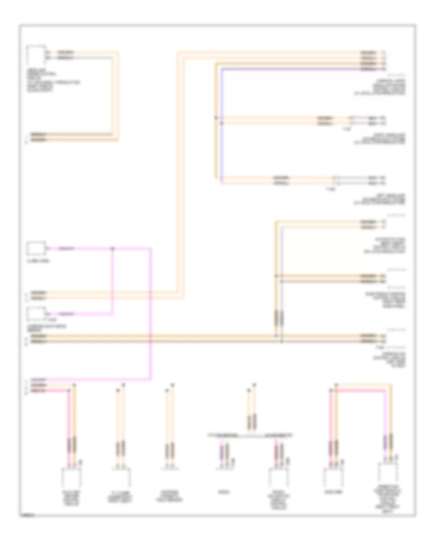
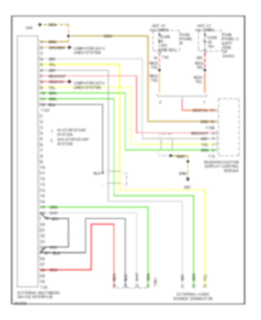
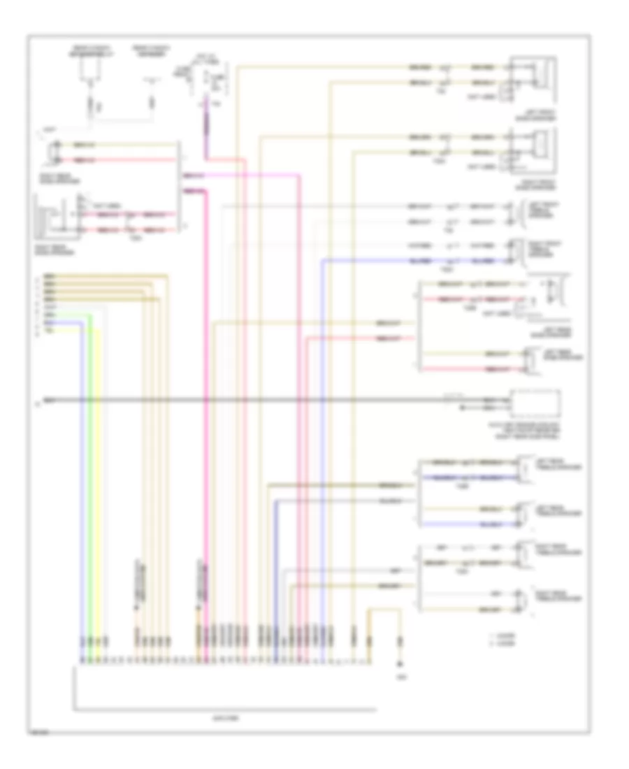
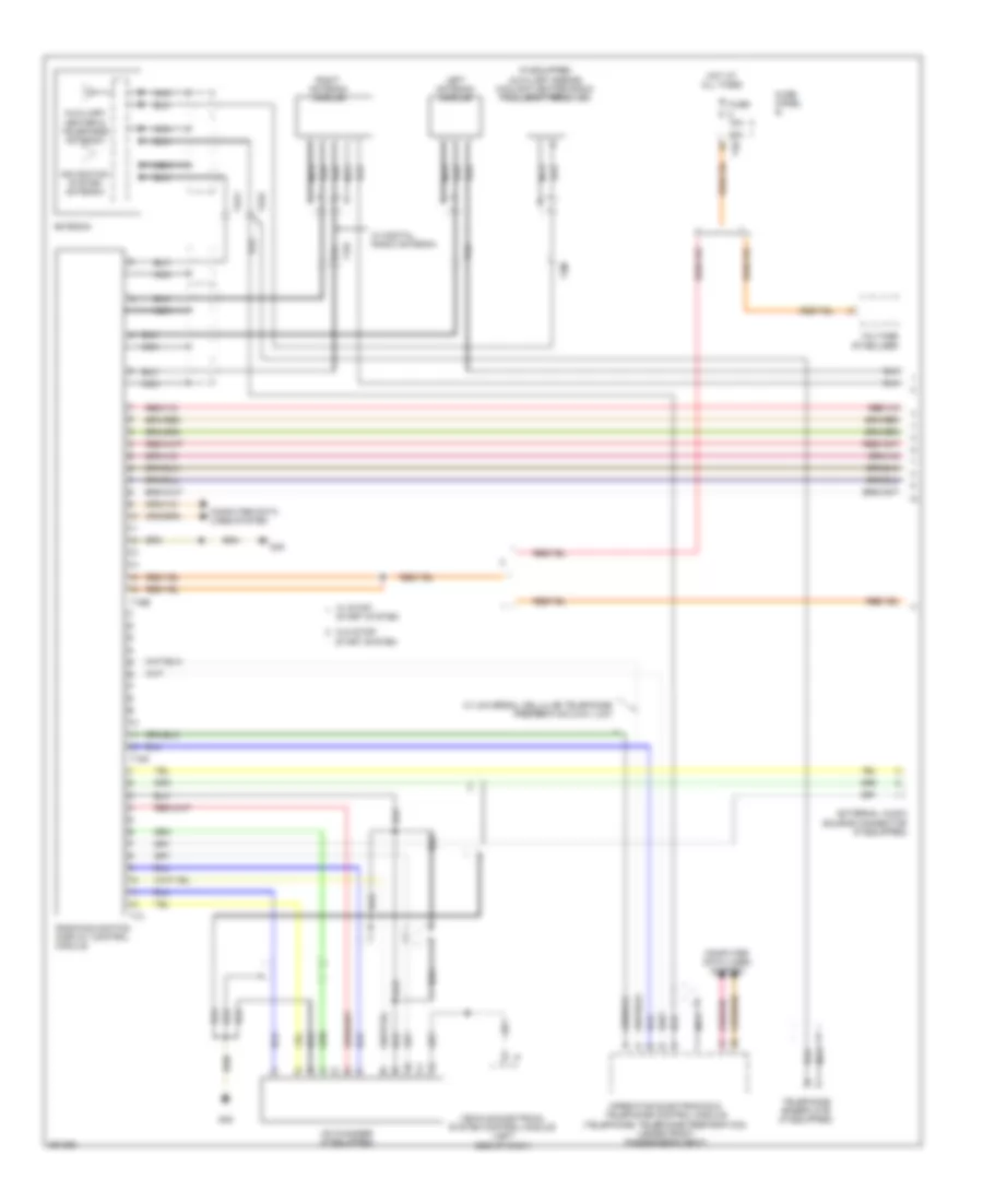
COMPUTER DATA LINES
Computer Data Lines Wiring Diagram (1 of 2) for Volkswagen Golf TDI 2010
List of elements for Computer Data Lines Wiring Diagram (1 of 2) for Volkswagen Golf TDI 2010:
- (left side of dash) vehicle electrical system control module
- (right rear door)
- 13a
- A/c control module
- Abs control module (right rear engine compt)
- Access/ start authorization control module
- Air bag control module (front of center console)
- All-wheel drive control module
- Automatic a/c
- Battery moni- toring system control module
- Climatronic control module
- Data bus on board diagnostic interface (left side of dash)
- Diagnostic connector (left side of dash)
- Direct shift gearbox mechatronic
- Driver's door control module (driver's door)
- Early production
- Engine control module (right rear of engine compt)
- Front passenger's door control module (front passenger's door)
- Fuse 10a
- Fuse 5a
- Fuse panel b
- Fuse panel c (left side of dash)
- G47 (right kick panel)
- Generator
- Hot at all times
- Instrument cluster control module
- Late production
- Left rear door control module (left rear door)
- Lin
- Manual a/c
- Power steering control module (front subframe)
- Rain/light recognition sensor
- Right rear door control module
- Selector lever sensor system control module
- Steering column electronic control module (steering column)
- T10s
- T12x
- T16r
- T18b
- T18c
- T20a
- T20b
- T20c
- T20d
- T20e
- T28
- T28a
- T28b
- T28c
- T2c
- T2i
- T32b
- T3ae
- T40
- T4q
- T52
- T52b
- T52c
- T5h
- T6z
- T75
- T8s
- T94
- Towing recognition control module (left rear side panel)
- Transmission control module (left front wheel housing)
- W/ esp
- W/ start/stop system
- W/ trailer socket
- W/o esp
- W/o trailer socket
- Wiper motor control module
Computer Data Lines Wiring Diagram (2 of 2) for Volkswagen Golf TDI 2010
List of elements for Computer Data Lines Wiring Diagram (2 of 2) for Volkswagen Golf TDI 2010:
- Alarm horn
- Amplifier
- Automatic high beam assist control module (on late production)
- Auxiliary heater control module
- Compass magnetic field sensor
- Corning lamps headlamp range control module (w/ hid & late production)
- Electronic damping control module (right rear side panel)
- Headlamp range control module (w/ hid & early production) (right side of glove compt)
- Interior monitoring sensor
- Left headlamp power output stage (w/ hid & late production)
- Operating electronic & telephone control module (right front seat)
- Parking aid control module (left side of dsh)
- Radio
- Radio/ navigation display control module
- Right headlamp power output stage (w/ hid & late production)
- T14e
- T14f
- T16b
- T16h
- T20k
- T38
- T4ap
- T54
- T8f
- Tv tuner (under right front seat)
- W/ navigation
- W/o navigation
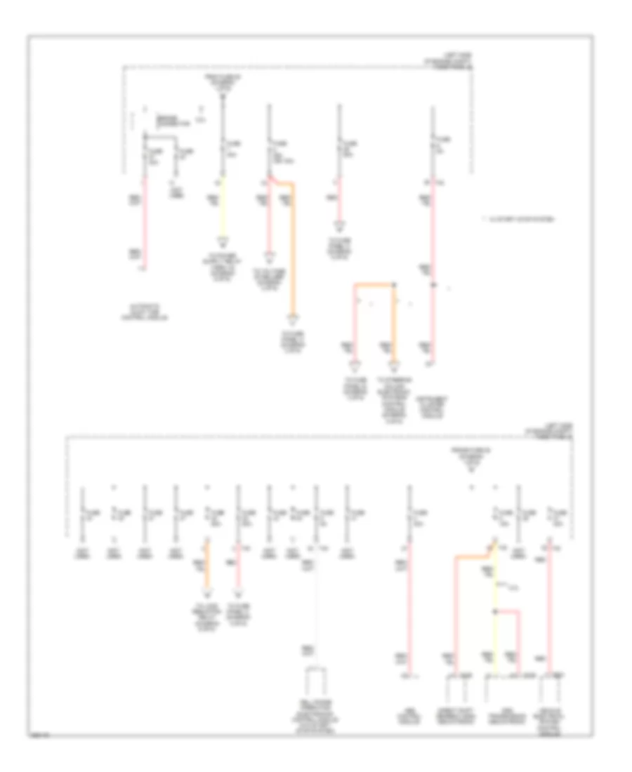
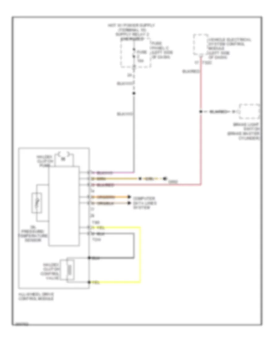
COOLING FAN
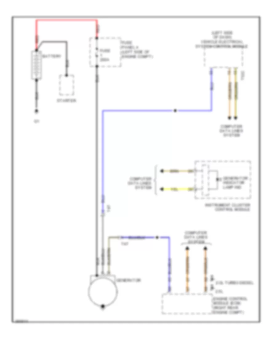
Cooling Fan Wiring Diagram for Volkswagen Golf TDI 2010
List of elements for Cooling Fan Wiring Diagram for Volkswagen Golf TDI 2010:
- (right rear of eng)
- 2.0l turbo diesel
- 2.5l
- Computer data lines system
- Coolant fan 2 (if equipped)
- Coolant fan control (fc) module
- Engine control module (ecm) (right rear of engine compt)
- Engine controls system
- Engine coolant temperature sensor (coolant pipe, left side of engine)
- Engine coolant temperature sensor (on radiator outlet)
- Engine coolant temperature sensor (on radiator outlet) (coolant pipe, left side of engine)
- Fuse 10a
- Fuse 50a
- Fuse panel a
- Fuse panel b
- G642 (electronic fan control)
- Hot at all times
- Nca
- Red
- T10l
- T2v
- T40
- T4x
- T60
- T94
CRUISE CONTROL
Cruise Control Wiring Diagram, Early Production for Volkswagen Golf TDI 2010
List of elements for Cruise Control Wiring Diagram, Early Production for Volkswagen Golf TDI 2010:
- (2.5l) throttle valve control module
- (left lower "a" pillar) g44
- (left plenum chamber) g607
- (on intake manifold)
- (upper steering column) g605
- 2.0l turbo diesel
- 2.5l
- A/t
- Accelerator pedal position sensor 2/accelerator pedal position sensor (accelerator pedal position sensor 2: accelerator pedal) assembly)
- Brake light switch (brake master cylinder)
- Clutch position sensor (m/t)
- Computer
- Computer data lines system
- Cruise control indicator lamp
- Cruise control switch
- Cruise control- set-button &
- Data lines system
- Distance regulation control module
- Distance regulation sensor heater
- Engine control module (right rear of engine compt)
- Engine speed (rpm) sensor (left rear
- Fuse 10a
- Fuse 30a 15a
- Fuse 5a
- Fuse panel b
- Fuse panel c (left side of dash)
- G605 (upper steering column)
- G642 (electronic fan control)
- Instrument cluster
- Instrument cluster control module
- M/t
- Multifunction transmission range switch (automatic transmission)
- Nca
- Of engine)
- Steering column electronic system control module (steering column)
- T14a
- T20d
- T40
- T52c
- T60
- T94
- Throttle position sensor & throttle valve control module (2.0l turbo diesel) (throttle position sensor : accelerator pedal assembly) (throttle valve control module: on intake manifold)
- Vehicle electrical system control module (left side of dash)
- W/ dsg transmission
- W/ m/t
Cruise Control Wiring Diagram, Late Production for Volkswagen Golf TDI 2010
List of elements for Cruise Control Wiring Diagram, Late Production for Volkswagen Golf TDI 2010:
- (2.5l) throttle valve control module
- (left lower "a" pillar) g44
- (left plenum chamber) g607
- (on intake manifold)
- 2.0l turbo diesel
- 2.5l
- A/t
- Accelerator pedal position sensor 2/accelerator pedal position sensor (accelerator pedal position sensor 2: accelerator pedal) assembly)
- Brake light switch (brake master cylinder)
- Clutch position sensor (m/t)
- Computer
- Computer data lines system
- Cruise control ind lamp
- Cruise control-set button & cruise control switch
- Data lines system
- Distance regulation control module
- Distance regulation sensor heater
- Engine control module (right rear of engine compt)
- Engine speed (rpm) sensor (left rear
- Fuse 10a
- Fuse 30a 15a
- Fuse 5a
- Fuse panel b (left side of engine compt)
- Fuse panel c (left side of dash)
- G605 (upper steering column)
- G642 (electronic fan control)
- Instrument cluster
- Instrument cluster control module
- M/t
- Multifunction transmission range switch (automatic transmission)
- Nca
- Of engine)
- Steering column electronic system control module (steering column)
- T14a
- T16r
- T40
- T52c
- T60
- T94
- T9a
- Throttle position sensor & throttle valve control module (2.0l turbo diesel) (throttle position sensor : accelerator pedal assembly) (throttle valve control module: on intake manifold)
- Vehicle electrical system control module (left side of dash)
- W/ dsg transmission
- W/ m/t
DEFOGGERS
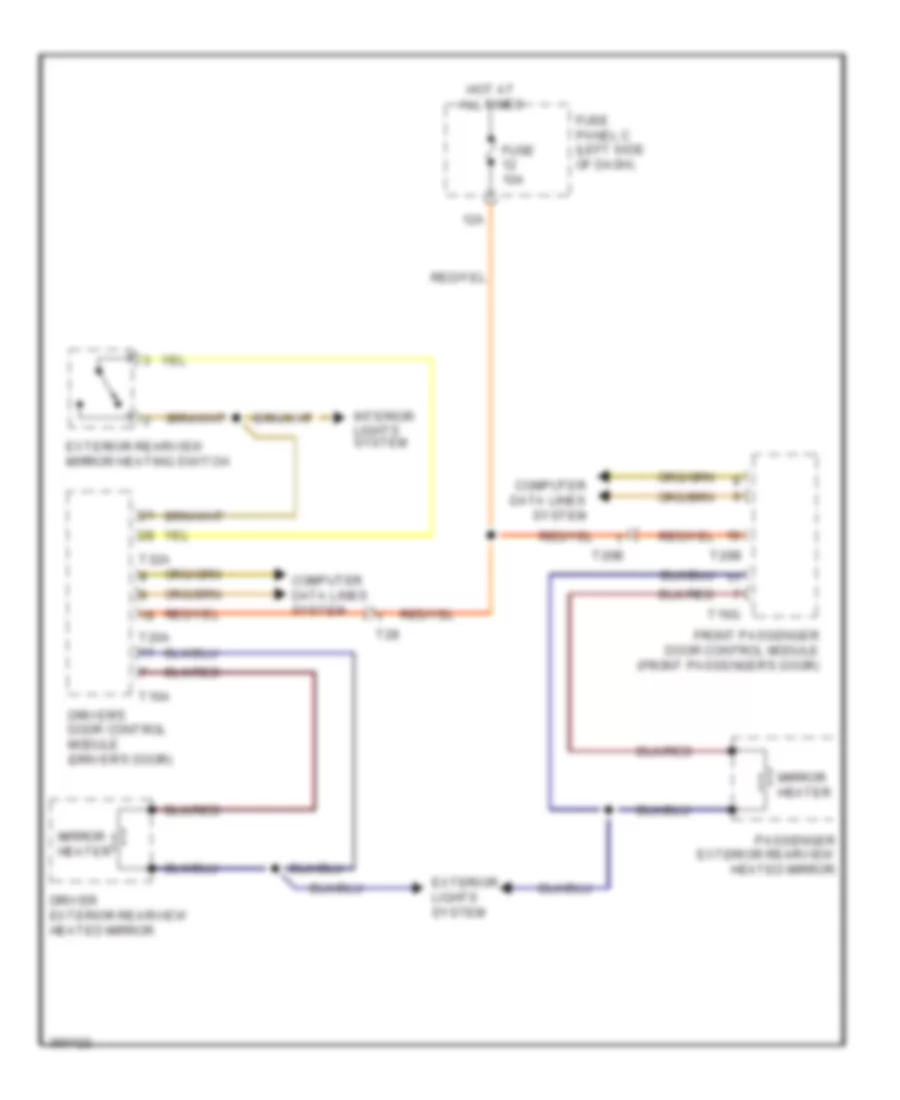
Heated Mirrors Wiring Diagram for Volkswagen Golf TDI 2010
List of elements for Heated Mirrors Wiring Diagram for Volkswagen Golf TDI 2010:
- 12a
- Computer data lines system
- Driver exterior rearview heated mirror
- Driver's door control module (driver's door)
- Exterior lights system
- Exterior rearview mirror heating switch
- Front passenger door control module (front passenger's door)
- Fuse 10a
- Fuse panel c (left side of dash)
- Hot at all times
- Interior lights system
- Mirror heater
- Passenger exterior rearview heated mirror
- T16a
- T16g
- T20a
- T20b
- T28
- T32a
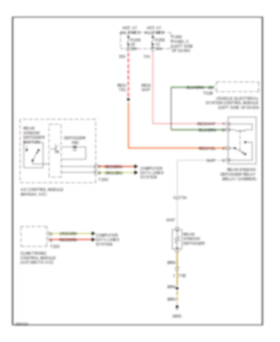
Rear Defogger Wiring Diagram for Volkswagen Golf TDI 2010
List of elements for Rear Defogger Wiring Diagram for Volkswagen Golf TDI 2010:
- 13a
- 25a
- A/c control module (manual a/c)
- Climatronic control module (automatic a/c)
- Computer data lines system
- Defogger ind
- Fuse 10a
- Fuse 25a
- Fuse panel c (left side of dash)
- G662
- Hot at all times
- Rear window defogger
- Rear window defogger button
- Rear window defogger relay (relay carrier)
- T20c
- T52b
- T5a
- T5e
- Vehicle electrical system control module (left side of dash)
ELECTRONIC POWER STEERING
Electronic Power Steering Wiring Diagram for Volkswagen Golf TDI 2010
List of elements for Electronic Power Steering Wiring Diagram for Volkswagen Golf TDI 2010:
- (left frame rail) g652
- Computer data lines system
- Electro- mechanical power steering indicator lamp
- Electro- mechanical power steering motor
- Fuse 10a
- Fuse 80a
- Fuse panel a
- Fuse panel c (left side of dash)
- Hot at all times
- Instrument cluster control module
- Power steering control module (front subframe)
- Red
- Steering angle sensor
- Steering torque sensor
- T2a
- T3bq
- T5g
- T5u
- T6z
ELECTRONIC SUSPENSION
Electronic Suspension Wiring Diagram for Volkswagen Golf TDI 2010
List of elements for Electronic Suspension Wiring Diagram for Volkswagen Golf TDI 2010:
- 35a
- Computer data lines system
- Dampening adjustment button & indicator lamp
- Electronic damping control module (right rear side panel)
- Fuse 10a
- Fuse 15a
- Fuse panel c (left side of dash)
- G44 (left lower "a" pillar)
- Hot at all times
- Interior lights system
- Left front body acceleration sensor
- Left front dampening adjustment valve
- Left front level control system sensor
- Left rear dampening adjustment valve
- Left rear level control system sensor
- Pnk
- Rear body acceleration sensor
- Red
- Right front body acceleration sensor
- Right front dampening adjustment valve
- Right front level control sensor
- Right rear dampening adjustment valve
ENGINE PERFORMANCE
2.0L TURBO DIESEL
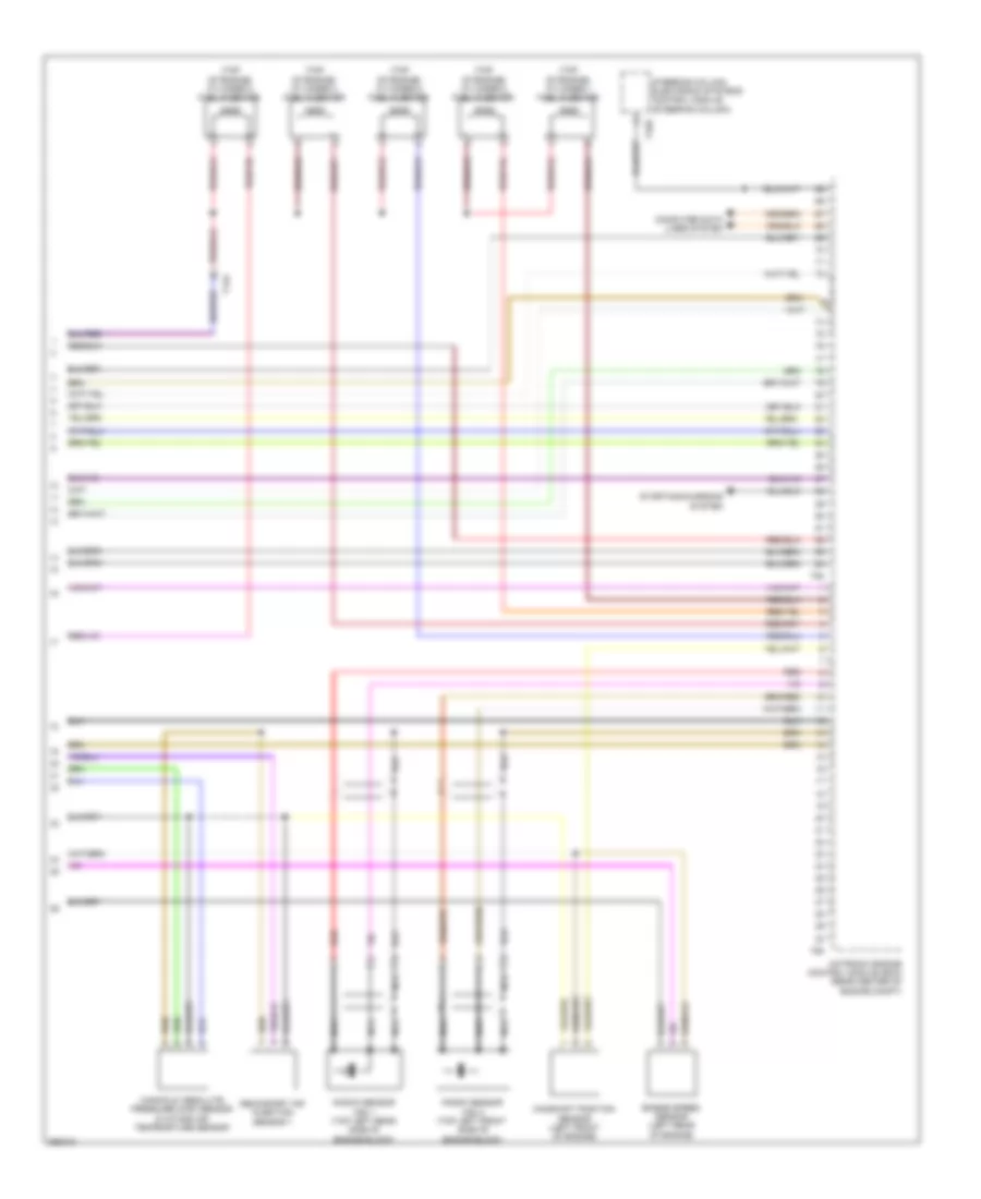
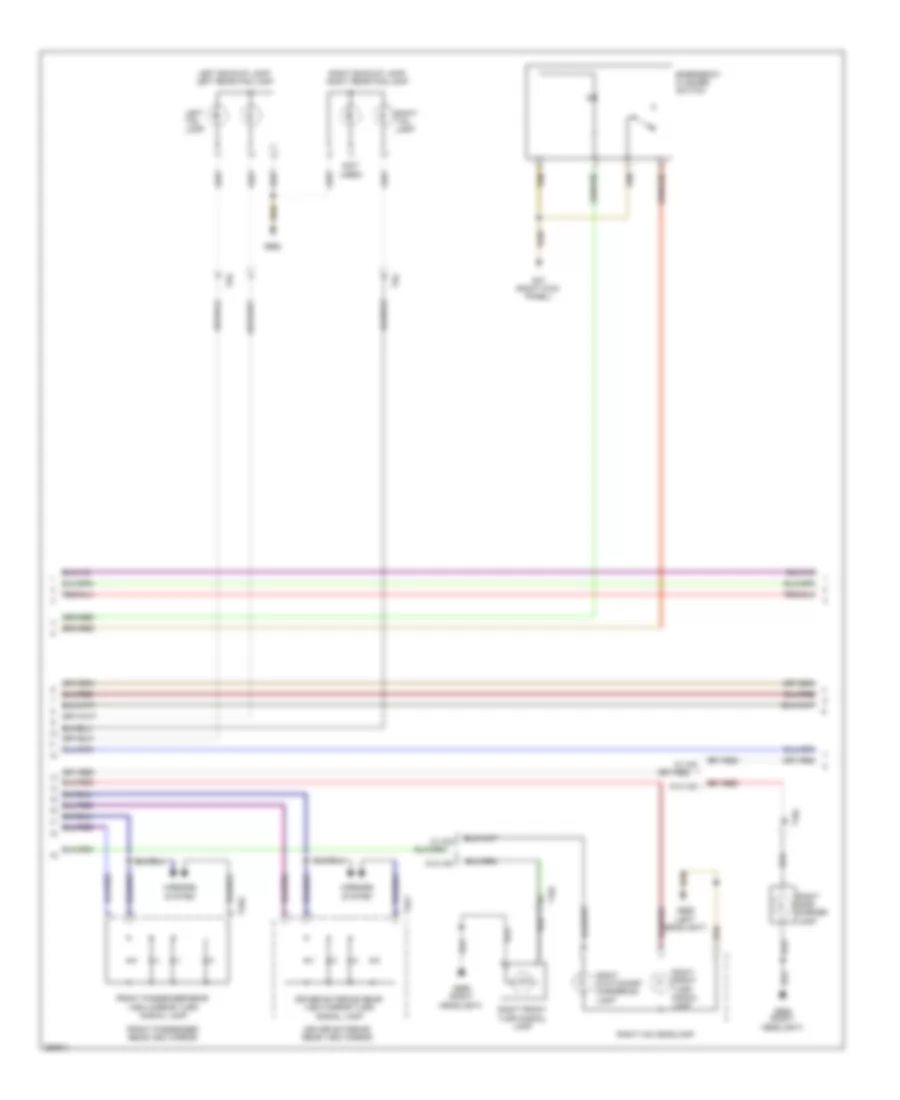
2.0L Turbo Diesel, Engine Performance Wiring Diagram (1 of 6) for Volkswagen Golf TDI 2010
List of elements for 2.0L Turbo Diesel, Engine Performance Wiring Diagram (1 of 6) for Volkswagen Golf TDI 2010:
- (accelerator pedal assembly) accelerator pedal position sensor 1 & 2
- (left front kick panel) g602
- (left plenum chamber) g607
- Auxiliary heater heating element (left side of hvac housing)
- Cooling fans system
- Cruise control system
- Engine control module (right rear engine compt)
- Engine coolant temperature sensor (on radiator) (coolant pipe, left side of engine)
- Exhaust gas temperature (egt) sensor 1
- Exhaust gas temperature (egt) sensor 2 (egr housing)
- Exhaust gas temperature (egt) sensor 3 (egr housing)
- Exhaust gas temperature (egt) sensor 4 (egr housing outlet)
- Fuse 10a
- Fuse 20a
- Fuse 30a
- Fuse 50a
- Fuse 5a
- Fuse panel b
- Heater/ heat output switch
- Hot at all times
- Late produc- tion early produc- tion
- Mass air flow (maf) sensor
- Red
- T10i
- T14a
- T20c
- T40
- T94
- Transmi- ssions system
2.0L Turbo Diesel, Engine Performance Wiring Diagram (2 of 6) for Volkswagen Golf TDI 2010
List of elements for 2.0L Turbo Diesel, Engine Performance Wiring Diagram (2 of 6) for Volkswagen Golf TDI 2010:
- (catalytic converter outlet pipe) oxygen sensor after three way catalytic converter & oxygen sensor 1 after catalytic converter heater
- (egr housing)
- (left side of dash) vehicle electrical system control module
- Differential pressure sensor
- Early production
- Egr cooler switch over valve
- Egr potenti- ometer & egr vacuum regulator solenoid valve
- Engine speed (rpm) sensor (left rear side of engine)
- Exhaust door control unit
- Exhaust pressure sensor 1 (auxiliary fuel pump bracket)
- Fuse 40a
- Fuse 80a
- Fuse panel a
- Heated oxygen sensor & oxygen sensor heater
- Hot at all times
- Late production
- Nca
- Red
- T10i
- T14a
- T52b
- T52c
- T5ab
2.0L Turbo Diesel, Engine Performance Wiring Diagram (3 of 6) for Volkswagen Golf TDI 2010
List of elements for 2.0L Turbo Diesel, Engine Performance Wiring Diagram (3 of 6) for Volkswagen Golf TDI 2010:
- (brake master cylinder) brake light switch
- (left lower "a" pillar) g44
- (relay carrier) high heat output relay
- (relay carrier) low heat output relay
- Abs control module (right rear engine compt)
- Engine preheating heating element
- Exterior socket (230v/110v)
- Fuel pressure sensor (fuel rail)
- G642 (electronic fan control)
- G655 (left headlight)
- Red
- T14a
- T2ap
- Throttle valve control module & throttle position sensor (on intake manifold & accelerator pedal assembly)
- Transmission
- W/ dsg
- W/o dsg transmission
2.0L Turbo Diesel, Engine Performance Wiring Diagram (4 of 6) for Volkswagen Golf TDI 2010
List of elements for 2.0L Turbo Diesel, Engine Performance Wiring Diagram (4 of 6) for Volkswagen Golf TDI 2010:
- (on relay carrier under engine compt e-box) automatic glow time control module
- (relay carrier) fuel primer relay
- (relay carrier) fuel pump relay
- (relay carrier) fuel pump relay 2
- Early
- Egr temperature sensor (intercooler housing)
- Engine control module (right rear engine compartment)
- Engine coolant temperature (ect) sensor (coolant pipe, left side of engine)
- Fuel level sensor & transfer fuel pump (fp)
- Fuel pump 2
- Fuel temperature sensor
- G655 (in left plenum chamber)
- G656 (right headlight)
- G682 (right rear side panel)
- Late
- Production
- T10i
- T14a
- T60
2.0L Turbo Diesel, Engine Performance Wiring Diagram (5 of 6) for Volkswagen Golf TDI 2010
List of elements for 2.0L Turbo Diesel, Engine Performance Wiring Diagram (5 of 6) for Volkswagen Golf TDI 2010:
- (auxiliary relay carrier)
- (left front of engine) oil pressure switch
- Camshaft position (cmp) sensor (left cylinder head cover)
- Computer data lines system
- Cruise control ind lamp
- Diesel particle filter indicator lamp
- Engine coolant level sensor
- Engine coolant level/temp (ecl/ect) ind lamp
- Engine coolant temperature (ect) gauge
- Engine electronics ind
- Fuel gauge
- Fuel metering valve
- Fuel pressure regulator valve (left rear of engine)
- Instrument cluster control module
- Internal pressure sensor cylinder 1 & glow plug 1
- Internal pressure sensor cylinder 2 & glow plug 2
- Internal pressure sensor cylinder 3 & glow plug 3
- Internal pressure sensor cylinder 4 & glow plug 4
- Low fuel level ind lamp
- Mil ind
- Nca
- Oil level ind lamp
- Oil pressure ind lamp
- Red
- T14a
2.0L Turbo Diesel, Engine Performance Wiring Diagram (6 of 6) for Volkswagen Golf TDI 2010
List of elements for 2.0L Turbo Diesel, Engine Performance Wiring Diagram (6 of 6) for Volkswagen Golf TDI 2010:
- (front of engine compartment) intake air temperature (iat) & charge air pressure sensor
- (if equipped) positive crankcase ventilation (pcv) heating element
- 27a
- Charge pressure actuator position sensor
- Computer data lines system
- Cooling fans system
- Cylinder fuel injectors (fuel rail)
- Engine control module (right rear engine compt)
- Exhaust gas recirculation (egr) position sensor 2 & motor 2
- Fuse 10a
- Fuse 15a
- Fuse panel c (left side of dash)
- Intake manifold runner position sensor & intake flap motor (front of intake manifold)
- Red
- Starting/charging system
- T14a
- T4bf
- T60
- T94
- Wastegate bypass regulator valve (turbocharger)
2.5L
2.5L, Engine Performance Wiring Diagram, Early Production (1 of 5) for Volkswagen Golf TDI 2010
List of elements for 2.5L, Engine Performance Wiring Diagram, Early Production (1 of 5) for Volkswagen Golf TDI 2010:
- Brake light switch/ w brake pedal switch (brake master cylinder)
- Clutch position sensor (m/t)
- Cooling fans system
- Engine coolant temperature sensor (radiator) (right rear of engine)
- Fuse 10a
- Fuse 15a
- Fuse 20a
- Fuse 40a
- Fuse 5a
- Fuse panel b
- G605 (upper steering column)
- G607 (left plenum chamber)
- Hot at all times
- Leak detection pump (ldp) (right rear wheelwell)
- Motronic engine control module (rear center of engine compt)
- Secondary air injection (air) pump relay
- T40
- T94
2.5L, Engine Performance Wiring Diagram, Early Production (2 of 5) for Volkswagen Golf TDI 2010
List of elements for 2.5L, Engine Performance Wiring Diagram, Early Production (2 of 5) for Volkswagen Golf TDI 2010:
- (left side of dash) vehicle electrical system control module
- (right rear engine compt) abs control module
- Accelerator pedal position sensor 2 (accelerator pedal assembly)
- Computer data lines system
- Engine preheating heating element
- Exterior socket 230v & 110v (w/ retrofitting)
- Fuse 10a
- Fuse panel c (left side of dash)
- G605 (upper steering column)
- G640
- G655 (left headlight)
- Heated oxygen sensor (exhaust manifold)
- Nca
- Oxygen sensor behind three way catalytic converter (if equipped) (rear of catalytic converter)
- Oxygen sensor in center three way catalytic converter (center of catalytic converter)
- Red
- Secondary air injection pump motor (lower left side of engine)
- T26a
- T2ap
- T47c
- T52b
- T52c
- W/ esp
- W/o esp
2.5L, Engine Performance Wiring Diagram, Early Production (3 of 5) for Volkswagen Golf TDI 2010
List of elements for 2.5L, Engine Performance Wiring Diagram, Early Production (3 of 5) for Volkswagen Golf TDI 2010:
- (coolant reservoir) engine coolant level (ecl) sensor
- (relay carrier) fuel primer relay
- (relay carrier) fuel pump relay
- (top of engine)
- 27a
- Fuse 15a
- Fuse panel c (left side of dash)
- G15
- G605 (upper steering column)
- G642 (electronic fan control)
- G682 (right rear side panel)
- Hot at all times
- Ignition coil 1 w/ power output stage
- Ignition coil 2 w/ power output stage
- Ignition coil 3 w/ power output stage
- Ignition coil 4 w/ power output stage
- Ignition coil 5 w/ power output stage
- Nca
- Red
- Secondary air injection solenoid valve (right rear of engine)
- Starter
- T14a
- To spark plug
- Transfer fuel pump/ fuel level sensor
2.5L, Engine Performance Wiring Diagram, Early Production (4 of 5) for Volkswagen Golf TDI 2010
List of elements for 2.5L, Engine Performance Wiring Diagram, Early Production (4 of 5) for Volkswagen Golf TDI 2010:
- (left front of engine) evaporative emission (evap) canister purge regulator valve 1
- (left front of engine) oil pressure switch
- (left rear of engine) camshaft adjustment valve 1
- Computer data lines system
- Electronic power control malfunction ind lamp
- Engine coolant temperature (ect) sensor (right rear of engine)
- Engine coolant temperature gauge
- Fuel gauge
- Instrument cluster
- Instrument cluster control module
- Low fuel level ind lamp
- Malfunction ind lamp
- Motronic engine control module (rear center of engine compt)
- Oil level ind lamp
- Oil pressure ind lamp
- T14a
- T60
- Throttle valve control module (on intake manifold)
2.5L, Engine Performance Wiring Diagram, Early Production (5 of 5) for Volkswagen Golf TDI 2010
List of elements for 2.5L, Engine Performance Wiring Diagram, Early Production (5 of 5) for Volkswagen Golf TDI 2010:
- (top of engine) cylinder 1 fuel injector
- (top of engine) cylinder 2 fuel injector
- (top of engine) cylinder 3 fuel injector
- (top of engine) cylinder 4 fuel injector
- (top of engine) cylinder 5 fuel injector
- Camshaft position sensor (left front of engine)
- Computer data lines system
- Engine speed sensor (left rear of engine)
- Knock sensor (ks) 1 (top left rear side of engine block)
- Knock sensor (ks) 2 (top left front side of engine block)
- Manifold absolute pressure (map) sensor & intake air temperature sensor
- Motronic engine control module (rear center of engine compt)
- Nca
- Red
- Secondary air injection sensor 1
- Starting/charging system
- Steering column electronic systems control module (steering column)
- T14a
- T16r
- T60
- T94
2.5L, Engine Performance Wiring Diagram, Late Production (1 of 5) for Volkswagen Golf TDI 2010
List of elements for 2.5L, Engine Performance Wiring Diagram, Late Production (1 of 5) for Volkswagen Golf TDI 2010:
- Brake light switch/ w brake pedal switch (brake master cylinder)
- Clutch position sensor (m/t)
- Cooling fans system
- Engine coolant temperature sensor (radiator) (right rear of engine)
- Fuse 10a
- Fuse 15a
- Fuse 20a
- Fuse 40a
- Fuse 5a
- Fuse panel b (left side of engine compt)
- G605 (upper steering column)
- G607 (left plenum chamber)
- Hot at all times
- Leak detection pump (ldp) (right rear wheelwell)
- Motronic engine control module (rear center of engine compt)
- Secondary air injection (air) pump relay
- T40
- T94
2.5L, Engine Performance Wiring Diagram, Late Production (2 of 5) for Volkswagen Golf TDI 2010
List of elements for 2.5L, Engine Performance Wiring Diagram, Late Production (2 of 5) for Volkswagen Golf TDI 2010:
- (left side of dash) vehicle electrical system control module
- (right rear engine compt) abs control module
- Accelerator pedal position sensor 2 (accelerator pedal assembly)
- Computer data lines system
- Engine preheating heating element
- Exterior socket 230v & 110v (w/ retrofitting)
- Fuse 10a
- Fuse panel c (left side of dash)
- G605 (upper steering column)
- G640
- G655 (left headlight)
- Heated oxygen sensor (exhaust manifold)
- Nca
- Oxygen sensor behind three way catalytic converter (if equipped) (rear of catalytic converter)
- Oxygen sensor center three way catalytic converter (center of catalytic converter)
- Red
- Secondary air injection pump motor (lower left side of engine)
- T26a
- T2ap
- T47c
- T52b
- T52c
- W/ esp
- W/o esp
2.5L, Engine Performance Wiring Diagram, Late Production (3 of 5) for Volkswagen Golf TDI 2010
List of elements for 2.5L, Engine Performance Wiring Diagram, Late Production (3 of 5) for Volkswagen Golf TDI 2010:
- (coolant reservoir) engine coolant level sensor
- (relay carrier) fuel pump relay
- (top of engine)
- 27a
- Fuse 15a
- Fuse panel c (left side of dash)
- G15
- G605 (upper steering column)
- G642 (electronic fan control)
- G682 (right rear side panel)
- Hot at all times
- Ignition coil 1 w/ power output stage
- Ignition coil 2 w/ power output stage
- Ignition coil 3 w/ power output stage
- Ignition coil 4 w/ power output stage
- Ignition coil 5 w/ power output stage
- Nca
- Red
- Secondary air injection solenoid valve (right rear of engine)
- Starter
- T14a
- To spark plug
- Transfer fuel pump/ fuel level sensor
2.5L, Engine Performance Wiring Diagram, Late Production (4 of 5) for Volkswagen Golf TDI 2010
List of elements for 2.5L, Engine Performance Wiring Diagram, Late Production (4 of 5) for Volkswagen Golf TDI 2010:
- (left front of engine) evaporative emission (evap) canister purge regulator valve 1
- (left front of engine) oil pressure switch
- (left rear of engine) camshaft adjustment valve 1
- Computer data lines system
- Electronic power control malfunction ind lamp
- Engine coolant temperature (ect) sensor (right rear of engine)
- Engine coolant temperature gauge
- Fuel gauge
- Instrument cluster
- Instrument cluster control module
- Low fuel level ind lamp
- Malfunction ind lamp
- Motronic engine control module (ecm) (rear center of engine compt)
- Oil level ind lamp
- Oil pressure ind lamp
- T14a
- T60
- Throttle valve control module (on intake manifold)
2.5L, Engine Performance Wiring Diagram, Late Production (5 of 5) for Volkswagen Golf TDI 2010
List of elements for 2.5L, Engine Performance Wiring Diagram, Late Production (5 of 5) for Volkswagen Golf TDI 2010:
- (top of engine) cylinder 1 fuel injector
- (top of engine) cylinder 2 fuel injector
- (top of engine) cylinder 3 fuel injector
- (top of engine) cylinder 4 fuel injector
- (top of engine) cylinder 5 fuel injector
- Camshaft position sensor (left front of engine)
- Computer data lines system
- Engine speed sensor (left rear of engine)
- Knock sensor (ks) 1 (top left rear side of engine block)
- Knock sensor (ks) 2 (top left front side of engine block)
- Manifold absolute pressure (map) sensor & intake air tempearture sensor
- Motronic engine control module (ecm) (rear center of engine compt)
- Nca
- Red
- Secondary air injection sensor 1
- Starting/charging system
- Steering column electronic systems control module (steering column)
- T14a
- T16r
- T60
- T94
EXTERIOR LIGHTS
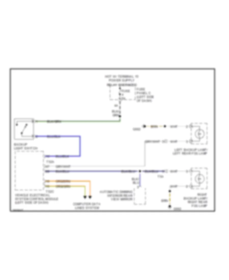
Backup Lamps Wiring Diagram, A/T for Volkswagen Golf TDI 2010
List of elements for Backup Lamps Wiring Diagram, A/T for Volkswagen Golf TDI 2010:
- 30a
- Automatic dimming interior rearview mirror
- Computer data lines system
- Fuse 20a
- Fuse panel c (left side of dash)
- G655 (left headlight)
- G662
- Left backup lamp/ left rear fog lamp
- Multi-function transmission range switch (automatic transmission)
- Nca
- Right backup lamp/ right rear fog lamp
- T52c
- T5a
- Transmission control module (left front wheel housing)
- Vehicle electrical system control module (left side of dash)
Backup Lamps Wiring Diagram, M/T for Volkswagen Golf TDI 2010
List of elements for Backup Lamps Wiring Diagram, M/T for Volkswagen Golf TDI 2010:
- Automatic dimming interior rear view mirror
- Backup light switch
- Computer data lines system
- Fuse 5a
- Fuse panel c (left side of dash)
- G662
- Left backup lamp/ left rear fog lamp
- Relay energized
- Right backup lamp/ right rear fog lamp
- T52a
- T52c
- T5a
- Vehicle electrical system control module (left side of dash)
Exterior Lamps Wiring Diagram, Early Production (1 of 3) for Volkswagen Golf TDI 2010
List of elements for Exterior Lamps Wiring Diagram, Early Production (1 of 3) for Volkswagen Golf TDI 2010:
- 13a
- 2.0l
- 2.5l
- Anti-lock brakes system
- Brake light switch (brake master cylinder)
- Computer data lines system
- Engine control module (right rear of engine compt)
- Fuse 10a
- Fuse 30a
- Fuse panel b
- Fuse panel c (left side of dash)
- G44 (left lower "a" pillar)
- G47 (right kick panel)
- G655 (left headlight)
- Hot at all times
- Interior lights system
- Left daytime running lamp & parking lamp (w/ hid)
- Left front position lamp
- Left front turn signal lamp
- Left hid headlamp
- Left side marker lamp
- Left stationary cornering lamp
- Light switch
- Rear fog lamp switch
- Red
- T10i
- T16a
- T16g
- T40
- T52a
- T52b
- T52c
- T94
- Vehicle electrical system control module (left side of dash)
- W/ hid
- W/o hid
- W/o hid w/ hid
Exterior Lamps Wiring Diagram, Early Production (2 of 3) for Volkswagen Golf TDI 2010
List of elements for Exterior Lamps Wiring Diagram, Early Production (2 of 3) for Volkswagen Golf TDI 2010:
- (not used)
- Driver exterior rear view mirror
- Driver exterior rear view mirror turn signal lamp
- Emergency flasher switch
- Front passenger rear view mirror
- Front passenger rear view mirror turn signal lamp
- G47 (right kick panel)
- G655 (left headlight)
- G656 (right headlight)
- G662
- Left backup lamp/ left rear fog lamp
- Left tail lamp
- Mirrors system
- Right backup lamp/ right rear fog lamp
- Right front turn signal lamp
- Right hid headlamp
- Right side marker lamp
- Right stationary cornering lamp
- Right tail lamp
- T10j
- T3ay
- T3az
- T5a
- T5e
- W/ hid
- W/o hid
Exterior Lamps Wiring Diagram, Early Production (3 of 3) for Volkswagen Golf TDI 2010
List of elements for Exterior Lamps Wiring Diagram, Early Production (3 of 3) for Volkswagen Golf TDI 2010:
- Computer data lines system
- Data bus on board diagnostic interface (left side of dash)
- Distance control
- G656 (right headlight)
- G662
- G682 (right rear side panel)
- High- mount brake light
- Instrument cluster
- Instrument cluster control module
- Lamp failure ind
- Left brake/ tail lamp
- Left license plate light
- Left rear turn signal lamp
- Left taillamp assembly
- Left turn signal indicator
- Nca
- Parking lamp ind
- Rear fog lamp ind
- Right brake/ tail lamp
- Right daytime running lamp & parking lamp (w/ hid)
- Right front position lamp
- Right license plate light
- Right rear turn signal lamp
- Right taillamp assembly
- Right turn signal indicator
- Steering column electronic systems control module (steering column)
- T20
- T20d
- T2aj
- T5a
- T8l
- Turn signal switch
- Turn signal switch & head lamp dimmer/flasher switch
- W/ hid
- W/ park
- W/o hid
- W/o park
Exterior Lamps Wiring Diagram, Late Production (1 of 3) for Volkswagen Golf TDI 2010
List of elements for Exterior Lamps Wiring Diagram, Late Production (1 of 3) for Volkswagen Golf TDI 2010:
- 13a
- 2.0l
- 2.5l
- Anti-lock brakes system
- Brake light switch (brake master cylinder)
- Computer data lines system
- Driver exterior rear view mirror
- Driver exterior rear view mirror turn signal lamp
- Engine control module (right rear of engine compt)
- Front passenger rear view mirror
- Front passenger rear view mirror turn signal lamp
- Fuse 10a
- Fuse 30a
- Fuse panel b (left side of engine compt)
- Fuse panel c (left side of dash)
- G44 (left lower "a" pillar)
- G655 (left headlight)
- G656 (right headlight)
- Hot at all times
- Left front turn signal lamp
- Light switch
- Mirrors system
- Rear fog lamp switch
- Red
- Right front turn signal lamp
- T10i
- T10j
- T16a
- T16g
- T3ay
- T3az
- T40
- T52a
- T52b
- T52c
- T5e
- T94
- Vehicle electrical system control module (left side of dash)
- W/ hid
- W/o hid
Exterior Lamps Wiring Diagram, Late Production (2 of 3) for Volkswagen Golf TDI 2010
List of elements for Exterior Lamps Wiring Diagram, Late Production (2 of 3) for Volkswagen Golf TDI 2010:
- (not used)
- Backup lamps circuit
- G655 (left headlight)
- G656 (right headlight)
- G662
- Lamp led module &
- Left backup lamp/ left rear fog lamp
- Left daytime running lamp & parking lamp led module
- Left daytime running lamp, parking lamp led module &
- Left side marker lamp
- Left tail lamp
- Right backup lamp/ right rear fog lamp
- Right daytime running lamp & parking lamp control module
- Right led daytime running lamp & parking lamp led module
- Right led daytime running lamp, parking
- Right side marker lamp
- Right tail lamp
- T10i
- T10j
- T14e
- T14f
- Temperature sensor
- W/ hid
- W/o hid
Exterior Lamps Wiring Diagram, Late Production (3 of 3) for Volkswagen Golf TDI 2010
List of elements for Exterior Lamps Wiring Diagram, Late Production (3 of 3) for Volkswagen Golf TDI 2010:
- Computer data lines system
- Data bus on board diagnostic interface (center of dash)
- Emergency flasher switch
- G47 (right kick panel)
- G662
- G682 (right rear side panel)
- High- mount brake light
- Instrument cluster
- Instrument cluster control module
- Lamp failure ind
- Left brake/ tail lamp
- Left license plate light
- Left rear turn signal lamp
- Left taillamp assembly
- Left turn signal indicator
- Parking lamp ind
- Rear fog lamp ind
- Right brake/ tail lamp
- Right license plate light
- Right rear turn signal lamp
- Right taillamp assembly
- Right turn signal indicator
- Signal switch
- Steering column electronic systems control module (on steering)
- T16r
- T20
- T2aj
- T5a
- T8ae
- T8l
- Turn
- Turn signal switch & headlamp dimmer/flasher switch
- W/ park distance control
- W/o park distance control
GROUND DISTRIBUTION
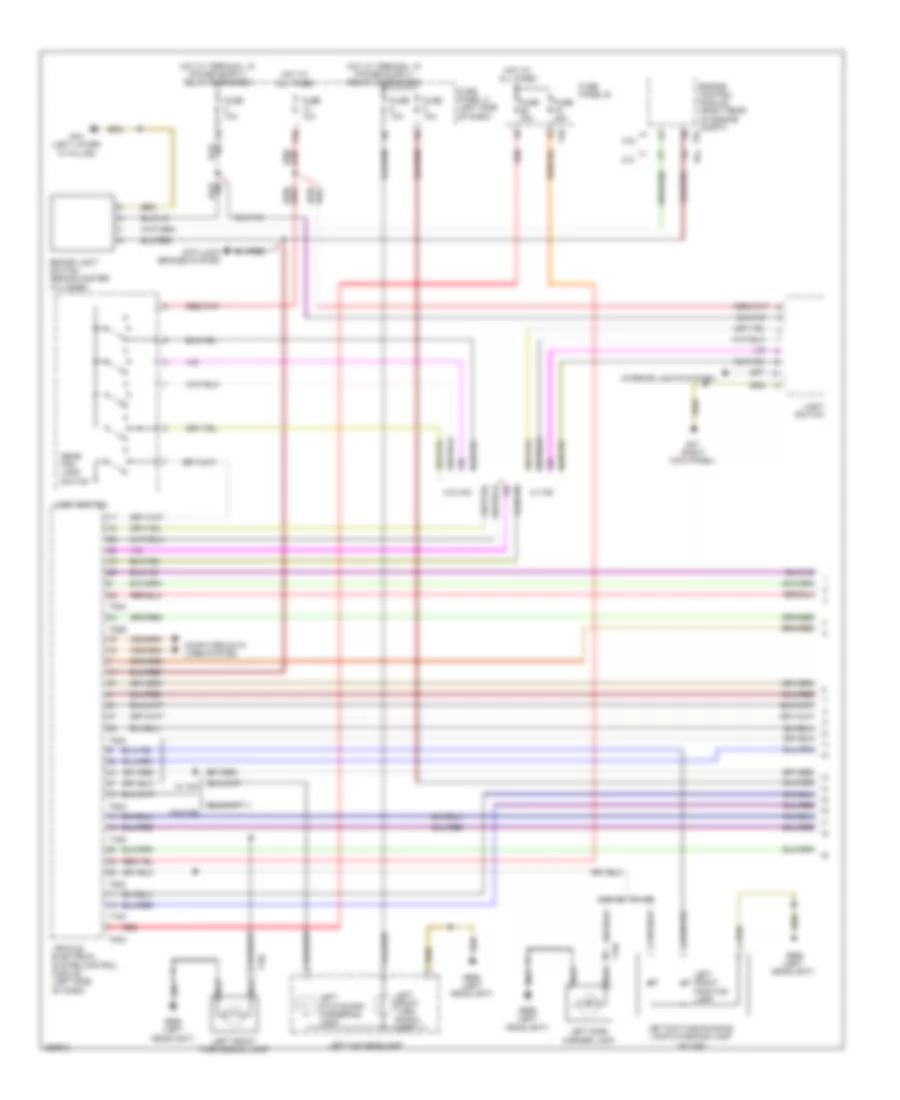
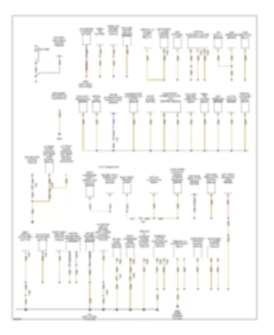
Ground Distribution Wiring Diagram, Early Production (1 of 4) for Volkswagen Golf TDI 2010
List of elements for Ground Distribution Wiring Diagram, Early Production (1 of 4) for Volkswagen Golf TDI 2010:
- "a" pillar)
- (if equipped) automatic dimming interior rearview mirror
- (if equipped) power sunroof control module
- (right lower
- (w/ front power windows) left rear central locking lock-motor
- (w/ rear power windows) left rear door control module
- (w/heated seats) driver's seat lumbar support adjustment switch
- Access/start authorization control module
- Air quality sensor
- Auxiliary heater operation relay
- Battery
- Battery monitoring control module
- Brake lamp switch
- Clutch position sensor
- Distance regulation control module
- Distance regulation sensor heater
- Driver backrest heating element
- Driver door control module
- Driver exterior door handle touch sensor
- Driver vanity mirror lamp contact switch
- Electronic damping control module
- Electronic steering column lock control module
- Flat conductor
- Fresh air blower relay
- Front passenger backrest heating element
- Front passenger heated seat temperature sensor
- Front passenger vanity mirror lamp contact switch
- Front seat heating control module
- G43
- G44 (left lower "a" pillar)
- G605 (upper steering column)
- G640
- Heated driver seat temperature sensor
- High pressure sensor
- Inclination adjustment button
- Instrument cluster control module
- Left footwell lamp
- Left front brake pad wear sensor
- Load reduction relay
- Nca
- Rain/light recognition sensor
- Red
- Right rear reading lamp
- Seat heating adjustment button
- Secondary air injection pump motor
- Start system button
- Steering column electronics control module
- Switch illumination bulb
- T10a
- T10b
- T16r
- T20d
- T28
- T28b
- T32b
- T4w
- T52b
- T52c
- T6c
- T8d
- Vehicle electrical system control module
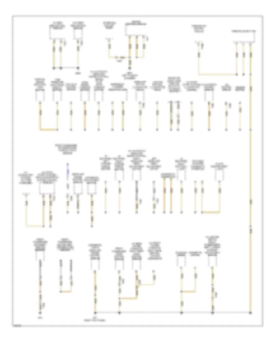
Ground Distribution Wiring Diagram, Early Production (2 of 4) for Volkswagen Golf TDI 2010
List of elements for Ground Distribution Wiring Diagram, Early Production (2 of 4) for Volkswagen Golf TDI 2010:
- (if equipped) left washer nozzle heater
- (if equipped) right footwell lamp
- (if equipped) right washer nozzle heater
- (w/ automatic headlamp range control) right headlamp beam adjustment motor
- (w/ esp) abs control module
- (w/ front power windows) right rear central locking lock motor
- (w/ rear power windows) right rear door control module
- (w/ stop/ start system) illumination control
- (w/ stop/ start system) vehicle electrical system control module
- (w/ stop/start system) voltage stabilizer
- (w/heated seats) front passenger's seat lumbar support adjustment switch
- (w/o esp) abs control module
- A/c control module
- Anti-slip control switch
- Asr/esp button
- Auxiliary heater heating element
- Blocking diode
- Brake fluid level warning switch
- Cigarette lighter illumination bulb
- Climatronic control module
- Converter w/ socket 12v-230v
- Dampening adjustment button
- Data bus on board diagnostic interface
- Diagnostic connection
- Emergency flasher button
- Exterior door handle touch sensor
- Fresh air blower
- Fresh air blower control module
- Front passenger
- Front passenger door control module
- G47 (right kick panel)
- G602 (left front kick panel)
- G638
- Glove compartment lamp
- Hand brake warning switch
- Headlamp range control module
- Headlamp switch illumination bulb
- Left headlamp beam adjustment motor
- Lighting control illumination bulb
- Lighting switch
- Parking aid button
- Parking aid control module
- Parking brake indicator lamp switch
- Push button illumination bulb
- Selector level park position switch & tiptronic switch
- T10b
- T10h
- T10i
- T10j
- T16m
- T20c
- T26a
- T28a
- T28c
- T47c
- T52a
- Tire pressure monitoring display button
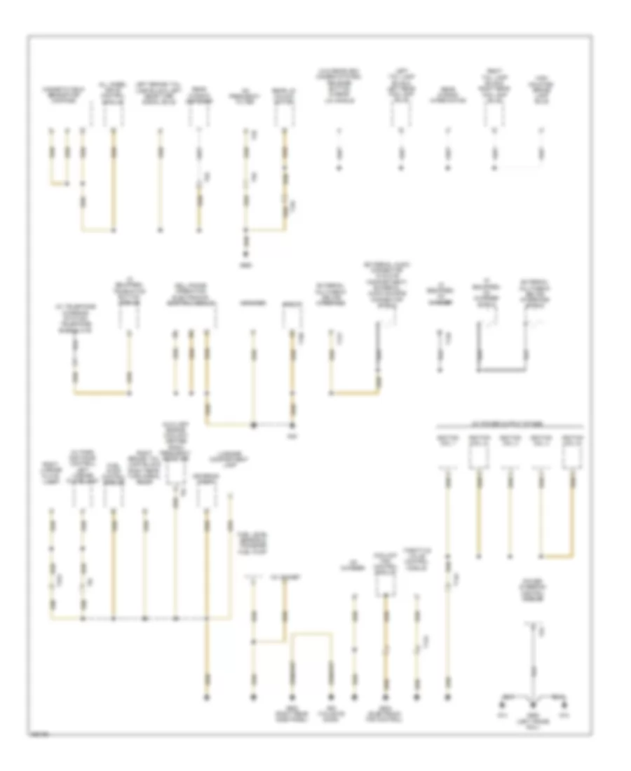
Ground Distribution Wiring Diagram, Early Production (3 of 4) for Volkswagen Golf TDI 2010
List of elements for Ground Distribution Wiring Diagram, Early Production (3 of 4) for Volkswagen Golf TDI 2010:
- (w/ anti-theft alarm system) alarm horn
- (w/ daytime running lights) left front fog lamp
- (w/ retrofitting) exterior socket
- 2.0l turbo
- 2.5l
- A/c compressor regulator valve
- Automatic glow time control module
- Auxiliary heater control module
- Brake fluid level warning switch
- Control module
- Dsg transmission mechatronic
- Engine hood contact switch
- Fuel pump 2
- G655 (left headlight)
- G656 (right headlight)
- Headlamp bulb
- Headlamp range/ cornering lamp control module
- Headlamp washer pump
- Heater coolant shut-off valve
- High tone horn
- Left daytime running lamp & parking lamp bulb
- Left front turn signal lamp
- Left headlamp power output stage
- Left hid
- Left high beam headlamp bulb
- Left low beam headlamp bulb
- Left low beam reflector motor
- Left parking lamp & left daytime running lamp
- Left side marker lamp bulb
- Low tone horn
- Muliti-function transmission range switch
- Nca
- Right daytime running lamp & right front positioning lamp
- Right front fog lamp bulb & right cornering lamp
- Right front turn signal lamp
- Right headlamp power output stage
- Right hid headlamp bulb
- Right high beam headlamp bulb
- Right low beam headlamp bulb
- Right low beam reflector motor
- Right parking lamp & right daytime running lamp
- Right side marker lamp bulb
- T10i
- T14e
- T14f
- T16j
- T16k
- T2bn
- T2g
- T4t
- Transmission
- Wiper motor control module
Ground Distribution Wiring Diagram, Early Production (4 of 4) for Volkswagen Golf TDI 2010
List of elements for Ground Distribution Wiring Diagram, Early Production (4 of 4) for Volkswagen Golf TDI 2010:
- (external audio connector in glove compartment) external audio source connector shield
- (if equipped) cd charger
- (if equipped) cd charger shield
- (w/ button module) telematics button switch
- (w/ park distance control) left license plate lamp
- (w/ power output stage)
- (w/ telephone charging station) telephone base plate
- (w/o rearview camera system) release button in rear lid handle
- 12v socket
- All wheel drive control module
- Am frequency filter
- Amplifier
- Auxiliary engine coolant heater radio frequency receiver
- Cd changer
- Cell phone operating electronics control module
- Coolant fan control module
- Engine control module
- External multimedia device interface
- External multimedia device interface shield
- Fuel level sensor & transfer fuel pump
- G12
- G14
- G45
- G53 (tailgate door)
- G607 (left plenum chamber)
- G642 (electronic fan control)
- G652 (left frame rail)
- G662
- G682 (right rear side panel)
- High mounted brake lamp bulb
- Ignition coil 1
- Ignition coil 2
- Ignition coil 3
- Ignition coil 4
- Ignition coil 5
- Left rear fog lamp bulb
- Left rear turn signal bulb
- Magnetic field sensor for compass
- Metering pump
- Nca
- Power steering control module
- Radio navigation display control module
- Rear lid unlock motor
- Rear window defogger
- Rear window wiper motor
- Right license plate lamp
- Right rear fog lamp bulb
- Right rear turn signal bulb
- T12d
- T12t
- T14a
- T15c
- T16b
- T2a
- T2aj
- T2b
- T4x
- T5e
- T6j
- T8i
- T94
- Throttle valve control module
Ground Distribution Wiring Diagram, Late Production (1 of 4) for Volkswagen Golf TDI 2010
List of elements for Ground Distribution Wiring Diagram, Late Production (1 of 4) for Volkswagen Golf TDI 2010:
- (if equipped) automatic dimming interior rearview mirror
- (vehicle w/ sunroof) power sunroof control module
- (w/ front power windows) left rear central locking- lock-motor
- (w/ rear power windows) left rear door control module
- (w/heated seats) driver's seat lumbar support adjustment switch
- Access/start authorization control module
- Air quality sensor
- Auxiliary heater heating element
- Auxiliary heater operation relay
- Battery
- Battery monitoring control module
- Brake lamp switch
- Clutch position sensor
- Converter w/ socket 12v-230v
- Distance regulation control module
- Distance regulation sensor heater
- Driver backrest heating element
- Driver door control module
- Driver exterior door handle touch sensor
- Driver vanity mirror lamp contact switch
- Electronic damping control module
- Electronic steering column lock control module
- Flat conductor
- Fresh air blower
- Fresh air blower control module
- Fresh air blower relay
- Front passenger door control module
- Front passenger vanity mirror lamp contact switch
- Front seat heating control module
- G44 (left lower 'a' pillar)
- G602 (left front kick panel)
- G605 (upper steering column)
- G640
- Heated driver seat temperature sensor
- High pressure sensor
- Inclination adjustment button
- Instrument cluster control module
- Left footwell lamp
- Left front brake pad wear sensor
- Load reduction relay
- Nca
- Rain/light recognition sensor
- Red
- Right rear reading lamp
- Seat heating adjustment button
- Secondary air injection pump motor
- Start system button
- Steering column electronics control module
- Switch illumination bulb
- T10a
- T16r
- T20a
- T20b
- T20d
- T28
- T28a
- T28b
- T32b
- T4w
- T52b
- T52c
- T8d
- Vehicle electrical system control module
Ground Distribution Wiring Diagram, Late Production (2 of 4) for Volkswagen Golf TDI 2010
List of elements for Ground Distribution Wiring Diagram, Late Production (2 of 4) for Volkswagen Golf TDI 2010:
- (if equipped) left washer nozzle heater
- (if equipped) right footwell lamp
- (if equipped) right washer nozzle heater
- (w/ automatic headlamp range control) brake fluid level warning switch
- (w/ automatic headlamp range control) right headlamp beam adjustment motor
- (w/ esp) abs control module
- (w/ front power windows) right rear central locking lock motor
- (w/ heated seats) front passenger's seat lumbar support adjustment switch
- (w/ rear power windows) right rear door control module
- (w/ stop/ start system) illumination control
- (w/ stop/ start system) vehicle electrical system control module
- (w/ stop/start system) voltage stabilizer
- (w/o esp) abs control module
- A/c control module
- After run coolant pump
- Anti-slip control switch
- Asr/esp button
- Blocking diode
- Cigarette lighter
- Climatronic control module
- Cornering lamp & headlamp range control module
- Dampening adjustment button
- Data bus on board diagnostic interface
- Diagnostic connection
- Emergency flasher indicator lamp
- Engine control module
- Exterior door handle touch sensor
- Front passenger
- Front passenger backrest heating element
- Front passenger door control module
- Front passenger heated seat temperature sensor
- G43
- G47 (right kick panel)
- G607 (left plenum chamber)
- G638
- Glove compartment lamp
- Hand- brake warning switch
- Headlamp range control module
- Headlamp switch illumination bulb
- Left headlamp beam adjustment motor
- Lighting control illumination bulb
- Parking aid button
- Parking aid control module
- Parking brake indicator lamp switch
- Selector level park position switch & tiptronic switch
- T10b
- T10h
- T10i
- T10j
- T16m
- T20c
- T26a
- T28a
- T28c
- T47c
- T4by
- T52a
- T94
- Tire pressure monitoring display button
Ground Distribution Wiring Diagram, Late Production (3 of 4) for Volkswagen Golf TDI 2010
List of elements for Ground Distribution Wiring Diagram, Late Production (3 of 4) for Volkswagen Golf TDI 2010:
- (if equipped) left front fog lamp & left cornering lamp bulb
- (if equipped) right front fog lamp bulb & right cornering lamp bulb
- (w/ anti-theft alarm system) alarm horn
- (w/ retrofitting) exterior socket
- 2.0l turbo
- 2.5l
- A/c compressor regulator valve
- Alarm horn
- Automatic glow time control module
- Auxiliary heater control module
- Brake fluid level warning switch
- Control module
- Dsg transmission mechatronic
- Engine hood contact switch
- Fuel pump 2
- G655 (left headlight)
- G656 (right headlight)
- Headlamp range/ cornering lamp control module
- Headlamp washer pump
- Heater coolant shut-off valve
- High tone horn
- Left adaptive cornering lamp motor
- Left day time running lamps & left high beam headlamp bulb
- Left front turn signal bulb
- Left headlamp power output stage
- Left hid headlamp control module
- Left low beam headlamp bulb
- Left low beam reflector motor
- Left parking lamp & left daytime running lamp
- Left side marker lamp bulb
- Low tone horn
- Muliti-function transmission range switch
- Nca
- Right day- time running lamps & right high beam headlamp bulb
- Right daytime running lamp & parking lamp control module
- Right front turn signal bulb
- Right front turn signal lamp
- Right headlamp power output stage
- Right hid headlamp control module
- Right high beam headlamp bulb
- Right low beam headlamp bulb
- Right low beam reflector motor
- Right side marker lamp bulb
- Sensor for right variable headlamp positioning motor
- T10j
- T14e
- T14f
- T16j
- T16k
- T2bn
- T2g
- T4t
- Transmission
- Wiper motor control module
Ground Distribution Wiring Diagram, Late Production (4 of 4) for Volkswagen Golf TDI 2010
List of elements for Ground Distribution Wiring Diagram, Late Production (4 of 4) for Volkswagen Golf TDI 2010:
- (external audio connector in glove compartment) external audio source connector shield
- (if equipped) cd charger
- (if equipped) cd charger shield
- (if equipped) telematics button module
- (w/ park distance control) left license plate lamp
- (w/ power output stage)
- (w/ telephone charging station) telephone base plate
- (w/o rearview camera system) release button in rear lid handle
- 12v socket
- All wheel drive control module
- Am frequency filter
- Amplifier
- Auxiliary engine coolant heater radio frequency receiver
- Cd changer
- Cell phone operating electronics control module
- Coolant fan control module
- External multimedia device interface
- External multimedia device interface shield
- Fuel level sensor & transfer fuel pump
- Fuel pump control module
- G12
- G14
- G45
- G53 (tailgate door)
- G642 (electronic fan control)
- G652 (left frame rail)
- G662
- G682 (right rear side panel)
- High mounted brake lamp bulb
- Ignition coil 1
- Ignition coil 2
- Ignition coil 3
- Ignition coil 4
- Ignition coil 5
- Left brake/ tail lamp bulb & left rear turn signal bulb
- Left tail lamp bulb & left rear fog lamp bulb
- Luggage compartment lamp
- Magnetic field sensor for compass
- Metering pump
- Power steering control module
- Radio
- Rear lid unlock motor
- Rear window defogger
- Rear window wiper motor
- Right brake/ tail lamp bulb & right rear turn signal bulb
- Right license plate lamp
- Right tail lamp bulb & right rear fog lamp bulb
- T12d
- T12t
- T14a
- T15c
- T16b
- T2a
- T2aj
- T2b
- T5e
- T6j
- T8i
- Throttle valve control module
HEADLIGHTS
Headlights Wiring Diagram, Early Production with HID Headlamps for Volkswagen Golf TDI 2010
List of elements for Headlights Wiring Diagram, Early Production with HID Headlamps for Volkswagen Golf TDI 2010:
- 13a
- Computer data lines system
- Fuse 10a
- Fuse panel c (left side of dash)
- G47 (right kick panel)
- G655 (left headlight)
- G656 (right headlight)
- Headlamp range control module
- High beam indicator
- Hot at all times
- Instrument cluster control module
- Left front positioning lamp
- Left headlamp assembly
- Left headlamp beam adjustment motor
- Left hid headlamp control module
- Left rear level control system sensor
- Light switch
- Rear fog lamp indicator
- Right front positioning lamp
- Right headlamp assembly
- Right headlamp beam adjustment motor
- Right hid headlamp control module
- T52a
- T52c
- Vehicle electrical system control module (left side of dash)
Headlights Wiring Diagram, Early Production without HID Headlamps for Volkswagen Golf TDI 2010
List of elements for Headlights Wiring Diagram, Early Production without HID Headlamps for Volkswagen Golf TDI 2010:
- 13a
- Computer data lines system
- Cruise control switch/ turn signal switch/ headlamp dimmer/ flasher switch
- Fog lamp
- Fuse 10a
- Fuse panel c (left side of dash)
- G655 (left headlight)
- G656 (right headlight)
- Headlamp dimmer/ flasher switch
- High beam indicator
- Hot at all times
- Instrument cluster control module
- Interior lights system
- Left day time running lamp (if equipped)
- Left front fog lamp/left cornering lamp (if equipped)
- Left high beam headlamp
- Left low beam headlamp
- Light switch
- Nca
- Rear fog lamp indicator
- Right day time running lamp (if equipped)
- Right front fog lamp/right cornering lamp (if equipped)
- Right high beam headlamp
- Right low beam headlamp
- Steering column electronic systems control module (steering column)
- T10i
- T10j
- T20d
- T52a
- T52c
- Vehicle electrical system control module (left side of dash)
- W/ fog lamps
Headlights Wiring Diagram, Late Production with HID Headlamps (1 of 2) for Volkswagen Golf TDI 2010
List of elements for Headlights Wiring Diagram, Late Production with HID Headlamps (1 of 2) for Volkswagen Golf TDI 2010:
- 13a
- Computer data lines system
- Fog lamp
- Fuse 10a
- Fuse 30a
- Fuse panel b (left side of engine compt)
- Fuse panel c (left side of dash)
- G47 (right kick panel)
- G655 (left headlight)
- G656 (right headlight)
- Headlamp dimmer/ flasher switch
- Headlamp range control module
- Hot at all times
- Interior lights system
- Left front fog lamp bulb
- Left hid headlamp bulb
- Left hid headlamp control module
- Left rear level control system sensor
- Light switch
- Red
- Right front fog lamp bulb
- Right hid headlamp bulb
- Right hid headlamp control module
- Steering column electronics control module (steering column)
- T14e
- T14f
- T16r
- T2ca
- T40
- T4az
- T52a
- T52c
- T8ae
- Vehicle electrical system control module (left side of dash)
- W/ fog lamps
Headlights Wiring Diagram, Late Production with HID Headlamps (2 of 2) for Volkswagen Golf TDI 2010
List of elements for Headlights Wiring Diagram, Late Production with HID Headlamps (2 of 2) for Volkswagen Golf TDI 2010:
- Computer data lines system
- Fuse 10a
- Fuse panel c (left side of dash)
- G655 (left headlight)
- G656 (right headlight)
- High beam indicator
- Instrument cluster control module
- Left adaptive cornering lamp motor
- Left daytime running lamp & parking lamp control module
- Left daytime running lamp & parking lamp led module
- Left daytime running lamp & parking lamp led module & temperature sensor
- Left headlamp beam adjustment motor
- Left headlamp power output stage
- Left low beam headlamp reflector motor
- Left swivel module position sensor
- Left variable headlamp positioning motor sensor
- Rear fog lamp indicator
- Right daytime running lamp & parking lamp control module
- Right daytime running lamp & parking lamp led module
- Right daytime running lamp & parking lamp led module & temperature sensor
- Right headlamp beam adjustment motor
- Right headlamp power output stage
- Right low beam headlamp reflector motor
- Right swivel module position sensor
- Right variable headlamp positioning motor sensor
- T14e
- T14f
- T2cc
- T2cd
- T6bq
- T6br
Headlights Wiring Diagram, Late Production without HID Headlamps for Volkswagen Golf TDI 2010
List of elements for Headlights Wiring Diagram, Late Production without HID Headlamps for Volkswagen Golf TDI 2010:
- 13a
- Computer data lines system
- Cruise control switch/ turn signal switch/ headlamp dimmer/ flasher switch
- Fog lamp
- Fuse 10a
- Fuse panel c (left side of dash)
- G655 (left headlight)
- G656 (right headlight)
- Headlamp dimmer/ flasher switch
- High beam indicator
- Hot at all times
- Instrument cluster control module
- Interior lights system
- Left daytime running lamp (if equipped)
- Left front fog lamp/ cornering lamp (if equipped)
- Left high beam headlamp
- Left low beam headlamp
- Light switch
- Rear fog lamp indicator
- Right daytime running lamp (if equipped)
- Right front fog lamp/ cornering lamp (if equipped)
- Right high beam headlamp
- Right low beam headlamp
- Steering column electronic systems control module (steering column)
- T10i
- T10j
- T16r
- T52a
- T52c
- T8ae
- Vehicle electrical system control module (left side of dash)
- W/ fog lamps
HORN
Horn Wiring Diagram, Early Production for Volkswagen Golf TDI 2010
List of elements for Horn Wiring Diagram, Early Production for Volkswagen Golf TDI 2010:
- (under steering wheel) airbag spiral spring/return spring w/ slip ring
- 17a
- 52a
- Computer data lines system
- Fuse 10a
- Fuse 40a
- Fuse 5a
- Fuse panel b
- Fuse panel c (left side of dash)
- G44 (behind left kick panel)
- G655 (below left headlight assembly)
- G656 (below right headlight assembly)
- High tone horn
- Hot at all times
- Low tone horn
- Multi-function steering wheel control module
- Nca
- Signal horn activation
- Steering column electronic systems control module (on steering column)
- T10x
- T12k
- T20d
- T40
- T5k
- Tone dual horn relay
- Vehicle electrical system control module (left side of dash)
- W/ multi-function steering wheel controls
- W/o multi-function steering wheel controls
Horn Wiring Diagram, Late Production for Volkswagen Golf TDI 2010
List of elements for Horn Wiring Diagram, Late Production for Volkswagen Golf TDI 2010:
- (under steering wheel) air bag spiral spring/return spring w/slip ring
- (upper steering column) g44
- 17a
- Computer data lines system
- Dual tone horn relay
- Fuse 10a
- Fuse 15a
- Fuse 5a
- Fuse panel b
- Fuse panel c (left side of dash)
- G655 (below left headlight assembly)
- G656 (below right headlight assembly)
- High tone horn
- Hot at all times
- Low tone horn
- Multi-function steering wheel control module (w/ multi-function steering wheel controls)
- Nca
- Signal horn activation
- Steering column electronic systems control module (on steering column)
- System
- T12k
- T16r
- T40
- T52b
- T52c
- T5k
- Vehicle electrical system control module (left side of dash)
- W/ multi-function steering wheel controls
- W/o multi-function steering wheel controls
- W/o start/stop
INSTRUMENT CLUSTER
Electronic Compass Wiring Diagram for Volkswagen Golf TDI 2010
List of elements for Electronic Compass Wiring Diagram for Volkswagen Golf TDI 2010:
- 13a
- 48a
- Compass magnetic field sensor
- Computer data lines system
- Fuse 10a 5a
- Fuse panel c (left side of dash)
- G662
- Hot at all times
- Instrument cluster
- Instrument cluster control module
- Multi- function indicator
- W/ start/stop system
- W/o start/stop system
Instrument Cluster Wiring Diagram (1 of 2) for Volkswagen Golf TDI 2010
List of elements for Instrument Cluster Wiring Diagram (1 of 2) for Volkswagen Golf TDI 2010:
- Abs warning lamp
- Air bag indicator lamp
- Air bag malfunction (mil) indicator
- Anti-theft immobilizer control module
- Anti-theft immobilizer indicator lamp
- Asr/esp indicator lamp
- Brake pad wear indicator lamp
- Brake system indicator lamp
- Computer data lines system
- Cruise control indicator lamp
- Diesel particulate filter indicator lamp
- Door ajar indicator lamp
- Electro- mechanical power steering indicator lamp
- Electronic power control malfunction indicator lamp
- Engine coolant level sensor (coolant reservoir)
- Engine coolant level/temperature (ecl/ect) indicator lamp
- Engine coolant temperature gauge
- Engine electronics indicator lamp
- Fuel gauge
- Fuel pump control module (below right rear seat)
- G44 (left lower "a" pillar)
- Generator (gen) indicator lamp
- Glow plug indicator lamp
- High beam indicator lamp
- Hood open indicator lamp
- Instrument cluster
- Instrument cluster control module
- Lamp failure indicator
- Left turn signal indicator lamp
- Low fuel level indicator lamp
- Malfunction indicator (mil) lamp
- Multi- function indicator
- Odometer display
- Oil level indicator lamp
- Oil pressure indicator lamp
- Outside air temperature sensor (left side of front grille)
- Parking lamp indicator
- Rear fog lamp indicator
- Right turn signal indicator lamp
- Safety belt warning lamp
- Seat belt indicator lamp
- Speedometer
- Tachometer
- Tire pressure monitoring display indicator lamp
- Traction control indicator lamp
- Warning buzzer & tone
- Windshield washer fluid level indicator lamp
- Windshield washer fluid level sensor
Instrument Cluster Wiring Diagram (2 of 2) for Volkswagen Golf TDI 2010
List of elements for Instrument Cluster Wiring Diagram (2 of 2) for Volkswagen Golf TDI 2010:
- (left rear door) (w/ rear power windows) left rear door control module
- (right rear door) (w/ rear power windows) right rear door control module
- Anti-theft immobilizer reader coil
- Brake fluid level warning switch (brake fluid reservoir)
- Computer data lines system
- Door contact switch
- Driver door central locking lock unit
- Driver door contact switch
- Driver's door control module (driver's door)
- Front passenger door central locking lock unit
- Front passenger's door contact switch
- Front passenger's door control module (front passenger's door)
- Fuel level sensor (fuel tank)
- Fuse 10a
- Fuse 5a
- Fuse panel b (left side of engine compt)
- Fuse panel c (left side of dash)
- G44 (left lower "a" pillar)
- G47 (right kick panel)
- G655 (left headlight)
- Hot at all times
- Left front brake pad wear sensor (if equipped)
- Left rear central locking lock unit
- Oil pressure switch (left front of engine)
- Parking brake indicator lamp switch
- Power sunroof control module
- Red
- Right rear central locking lock unit
- T14a
- T20a
- T20b
- T28
- T28a
- T28b
- T28c
- T40
- W/ rear power windows
INTERIOR LIGHTS
Courtesy Lamps Wiring Diagram (1 of 2) for Volkswagen Golf TDI 2010
List of elements for Courtesy Lamps Wiring Diagram (1 of 2) for Volkswagen Golf TDI 2010:
- (4 door w/ front power windows) right rear central locking lock unit
- Automatic day/night interior mirror
- Computer data lines system
- Door contact switch
- Driver's door central locking lock unit
- Driver's door control module (driver's door)
- Driver's entry lamp
- Driver's exterior rearview mirror
- Front interior lamp
- Front interior light/ driver reading lamp
- Front passenger's door central locking lock unit
- Front passenger's door control module (front passenger's door)
- Front passenger's entry lamp
- Front passenger's exterior rearview mirror
- Front passenger's reading light
- Fuse 20a
- Fuse 30a
- Fuse panel c (left side of dash)
- G44 (left lower "a" pillar)
- G44 (left lower "a" piller)
- G47 (right kick panel)
- Glove compartment lamp switch
- Glove compartment light
- Hot at all times
- Left rear central locking lock unit (4 door w/ front power windows)
- Nca
- T16a
- T16g
- T20a
- T20b
- T28
- T28a
- T28b
- T28c
- T3ay
- T3az
- T52a
- T52b
- T52c
- T8d
- Vehicle electrical system control module (left side of dash)
- W/ rear power windows
Courtesy Lamps Wiring Diagram (2 of 2) for Volkswagen Golf TDI 2010
List of elements for Courtesy Lamps Wiring Diagram (2 of 2) for Volkswagen Golf TDI 2010:
- (left rear door) (4 door w/ rear power windows) left rear door control module
- (right rear door) (4 door w/ rear power windows) right rear door control module
- Door contact switch
- Driver's vanity mirror contact switch
- Driver's vanity mirror lamp
- Front passenger's vanity mirror contact switch
- Front passenger's vanity mirror lamp
- G44 (left lower "a" pillar)
- G47 (right kick panel)
- G662
- Left footwell light
- Left rear central locking lock unit
- Left rear reading light
- Luggage compartment light
- Luggage compartment light switch
- Nca
- Rear courtesy/ reading lights
- Rear interior light
- Rear lid lock unit
- Right footwell light
- Right rear central locking lock unit
- Right rear reading light
- T28
- T28a
- T28b
- T28c
- T5c
- T8d
Instrument Illumination Wiring Diagram (1 of 2) for Volkswagen Golf TDI 2010
List of elements for Instrument Illumination Wiring Diagram (1 of 2) for Volkswagen Golf TDI 2010:
- (if equipped) cd changer
- (w/ 6-speed) tiptronic switch
- (w/ direct shift) selector lever sensors control module
- 13a
- 15a
- Asr/ esp button
- Cigarette lighter illumination bulb
- Computer data lines system
- Fuse 10a
- Fuse 20a
- Fuse panel c (left side of dash)
- G47 (right kick panel)
- Heater/heat output switch
- Hot at all times
- Instrument cluster control module
- Instrument panel lamp dimmer switch
- Light switch
- T10s
- T52a
- T52b
- T52c
- Tire pressure monitoring display button (if equipped)
- Vehicle electrical system control module (left side of dash)
Instrument Illumination Wiring Diagram (2 of 2) for Volkswagen Golf TDI 2010
List of elements for Instrument Illumination Wiring Diagram (2 of 2) for Volkswagen Golf TDI 2010:
- Computer data lines system
- Driver's door control module (driver's door)
- Driver's interior locking button
- Exterior rearview mirror switch
- Front interior lamp
- Front passenger's door control module (front passenger's door)
- Fuse 30a
- Fuse panel c (left side of dash)
- G44 (left lower "a" pillar)
- G47 (behind right kick panel)
- G47 (right kick panel)
- Hot at all times
- Left rear door control module (4 door w/ rear power windows) (left rear door)
- Left rear window switch
- Power window regulator switch (2 door & 4 door w/ front power windows)
- Power window regulator switch (4 door w/ rear power windows)
- Right front door window switch
- Right rear door control module (4 door w/ rear power windows) (right rear door)
- Right rear window switch
- T18c
- T18d
- T20a
- T20b
- T28
- T28a
- T28b
- T28c
- T32a
- T32b
NAVIGATION
Navigation Wiring Diagram, with Amplifier (1 of 2) for Volkswagen Golf TDI 2010
List of elements for Navigation Wiring Diagram, with Amplifier (1 of 2) for Volkswagen Golf TDI 2010:
- (in rear lid) am frequency filter
- (right kick panel)
- 2ay
- 2az
- Antenna
- Auxiliary heater antenna & telephone antenna
- Cd changer
- Computer data lines system
- Digital radio antenna
- External audio source connector (if equipped)
- Fm frequency filter (positive wire)
- Fuse 10a
- Fuse 15a
- Fuse 15a 25a
- Fuse panel b
- Fuse panel c (left side of dash)
- G45
- G47
- G662
- Heated rear window
- Hot at all times
- Left antenna module
- Navigation system antenna
- Nca
- Operating electronics & telephone control module (if equipped) (right front seat)
- Radio antenna
- Radio/navigation display control module
- Red
- Right antenna module
- T12
- T12g
- T16b
- T1a
- T1b
- T1c
- T1d
- T1e
- T1f
- T1g
- T1h
- T1i
- T1j
- T1w
- T2b
- T40
- T5e
- Vehicle electrical system control module (left side of dash)
- Voltage stabilizer (w/ stop/ start system)
- W/ digital radio antenna
- W/ stop/start system
- W/o stop/start system
Navigation Wiring Diagram, with Amplifier (2 of 2) for Volkswagen Golf TDI 2010
List of elements for Navigation Wiring Diagram, with Amplifier (2 of 2) for Volkswagen Golf TDI 2010:
- (not used)
- 2-door
- 4-door
- Amplifier
- Auxiliary engine coolant heating rf receiver (right rear side panel)
- Computer data lines system
- Fuse 30a
- Fuse penal b
- G45
- Hot at all times
- Left front bass speaker
- Left front treble speaker
- Left rear bass speaker
- Left rear treble speaker
- Lines system computer data
- Nca
- Rear window defogger
- Rear window defogger relay
- Right front bass speaker
- Right front treble speaker
- Right rear bass speaker
- Right rear treble speaker
- T28
- T28a
- T28b
- T28c
- T40
- T5a
Navigation Wiring Diagram, without Amplifier (1 of 2) for Volkswagen Golf TDI 2010
List of elements for Navigation Wiring Diagram, without Amplifier (1 of 2) for Volkswagen Golf TDI 2010:
- (if equipped) auxiliary engine coolant heater radio frequency receiver
- 25a
- Antenna
- Auxiliary heater & telephone antenna
- Cd changer (if equipped)
- Computer data lines system
- External audio source connector (if equipped)
- Fuse 15a
- Fuse panel b
- G45
- Hot at all times
- Left antenna module
- Navigation system antenna
- Nca
- Operating electronics & telephone control module (telephone/ telephone preparation) (under front passenger's seat)
- Radio/navigation display control module
- Right antenna module
- Start system
- T12
- T12g
- T16b
- T1e
- T1f
- T1w
- T2ay
- T2az
- T2m
- T40
- Telephone baseplate (if equipped)
- Vehicle electrical system control module (left side of dash)
- Voltage stabilizer
- W/ digital radio antenna
- W/ stop/
- W/ universal cellular telephone preperation (uhv) low
- W/o stop/ start system
Navigation Wiring Diagram, without Amplifier (2 of 2) for Volkswagen Golf TDI 2010
List of elements for Navigation Wiring Diagram, without Amplifier (2 of 2) for Volkswagen Golf TDI 2010:
- (in rear lid) am frequency filter
- 2 door w/ rear speaker 4 door w/ rear speaker
- 28a
- 4 door w/ rear speaker
- Antenna
- Digital radio antenna (if equipped)
- Fm frequency filter (positive wire)
- Fuse 15a
- Fuse panel c (left side of dash)
- G662
- Heated rear window
- Hot at all times
- Left front bass speaker
- Left front treble speaker
- Left rear bass speaker
- Left rear treble speaker
- Radio antenna
- Rear window defogger
- Rear window defogger relay
- Red
- Right front bass speaker
- Right front treble speaker
- Right rear bass speaker
- Right rear treble speaker
- T1a
- T1b
- T1c
- T1d
- T1i
- T1j
- T28
- T28a
- T28c
- T2b
- T5a
- T5e
Parking Assistant Wiring Diagram for Volkswagen Golf TDI 2010
List of elements for Parking Assistant Wiring Diagram for Volkswagen Golf TDI 2010:
- (left side of dash) vehicle electrical system control module
- Computer data lines system
- Front parking aid warning buzzer
- Fuse 10a
- Fuse panel c (left side of dash)
- G47 (right kick panel)
- Left front center parking aid sensor
- Left front parking aid sensor
- Left rear center parking aid sensor
- Left rear parking aid sensor
- Parking aid control module (left side of dash)
- Push button illumination bulb
- Rear parking aid warning buzzer
- Right front center parking aid sensor
- Right front parking aid sensor
- Right rear center parking aid sensor
- Right rear parking aid sensor
- T12n
- T12v
- T16m
- T52b
- T8l
- T8w
POWER DISTRIBUTION
Power Distribution Wiring Diagram, Early Production (1 of 6) for Volkswagen Golf TDI 2010
List of elements for Power Distribution Wiring Diagram, Early Production (1 of 6) for Volkswagen Golf TDI 2010:
- (not used)
- Abs control module
- Amplifier
- Battery
- Battery monitoring control module (w/ start/ stop system)
- Brake light switch (w/ dsg transmission)
- Coolant fan control module
- Data bus on board diagnostic interface
- Dual tone horn relay
- From fuse 3 (diagram 1 of 6)
- From fuse 5 (diagram 1 of 6)
- Fuse
- Fuse 150a 200a
- Fuse 30a
- Fuse 40a
- Fuse 50a
- Fuse 5a
- Fuse 80a
- Fuse panel a
- Fuse panel b
- G1 (battery to body)
- Generator
- Nca
- Power steering control module
- Red
- Starter
- T2a
- T2c
- T38
- T40
- T4x
- T52a
- T52c
- To battery monitoring control module (diagram 1 of 6)
- To fuse 12 (diagram 4 of 6)
- To fuse 19 (diagram 2 of 6)
- To fuse 25 (diagram 1 of 6)
- To fuse 3 (diagram 2 of 6)
- To fuse panel c (diagram 4 of 6)
- Vehicle electrical system control module
- W/ 140a generator
- W/ 90a/120a generator
- Wiper motor control module
Power Distribution Wiring Diagram, Early Production (2 of 6) for Volkswagen Golf TDI 2010
List of elements for Power Distribution Wiring Diagram, Early Production (2 of 6) for Volkswagen Golf TDI 2010:
- (left side of engine compt) fuse panel b
- (not used)
- 2.0l
- Abs control module
- Automatic glow time control module
- Bridge connector
- Cell phone operating electronics control module (w/o start/ stop system)
- Direct shift gearbox (dsg) mechatronic
- Dsg transmission mechatronic
- From fuse 25 (diagram 1 of 6)
- Frome fuse 25 (diagram 1 of 6)
- Fuse
- Fuse 15a
- Fuse 25a (or 15a)
- Fuse 30a
- Fuse 40a
- Fuse 50a
- Fuse 5a
- Instrument cluster control module
- Red
- T20e
- T40
- T52a
- To fuse panel b (diagram 3 of 6)
- To fuse panel c (diagram 3 of 6)
- To fuse panel c (diagram 5 of 6)
- To load reduction relay (diagram 6 of 6)
- To steering column electronic systems control module (diagram 5 of 6)
- To voltage stabilizer (diagram 3 of 6)
- Vehicle electrical system control module
- W/ start/ stop system
Power Distribution Wiring Diagram, Early Production (3 of 6) for Volkswagen Golf TDI 2010
List of elements for Power Distribution Wiring Diagram, Early Production (3 of 6) for Volkswagen Golf TDI 2010:
- (left side of dash) fuse panel c
- 10a
- 12a
- 13a
- 14a
- 15a
- 17a
- 28a
- 47a
- 48a
- A/c control module (manual a/c)
- Auxiliary engine coolant heater radio frequency receiver
- Cell phone operating electronics control module
- Climatronic control module (automatic a/c)
- Compass magnetic field sensor
- Data link connector
- Driver's door control module
- Dual tone horn relay
- From fuse 2 (diagram 6 of 6)
- From fuse 8 (diagram 2 of 6)
- From fuse 8 h (diagram 2 of 6)
- From fuse panel b (diagram 2 of 6)
- From fuse panel c (diagram 3 of 6)
- Front passenger's door control module
- Fuse 10a
- Fuse 15a
- Fuse 20a
- Fuse 5a
- G47 (right kick panel)
- Heater/ heat output switch
- Left rear control module (w/ rear power windows)
- Light switch
- Radio
- Rain/light recognition sensor (if equipped)
- Rear window defogger relay
- Red
- Right rear control module (w/ rear power windows)
- Selector lever
- Starter relay 2
- T10s
- T16b
- T20a
- T20b
- T20c
- T28
- T28a
- T28b
- T28c
- T52
- T52b
- T52c
- Transmission control module
- Vehicle electrical system control module
- Vehicle electrical system control module (w/ anti theft alarm system)
- Voltage stabilizer (w/ stop/ start system)
- W/ stop/start system
- W/o stop/start system
Power Distribution Wiring Diagram, Early Production (4 of 6) for Volkswagen Golf TDI 2010
List of elements for Power Distribution Wiring Diagram, Early Production (4 of 6) for Volkswagen Golf TDI 2010:
- (2.0l)
- (2.5l)
- (left side of engine compt) fuse panel b
- (terminal 30)
- 12v socket
- 20a
- 21a
- 22a
- 23a
- 24a
- 25a
- 26a
- 27a
- 40a
- 41a
- 42a
- A/c control module
- Access start authorization control module
- Auxiliary heater control module
- Auxiliary heater operation relay
- Blocking diode
- Cigarette lighter
- Data bus on board diagnostic interface
- Driver's door control module
- Electronic steering column lock control module
- Engine control module
- Fresh air blower control module
- Fresh air blower relay (manual a/c)
- From fuse 6 (diagram 1 of 6)
- From fuse panel a (diagram 1 of 6)
- From load induction relay (diagram 6 of 6)
- Front passenger's door control module
- Fuel primer relay
- Fuel pump relay
- Fuel pump relay 2 (2.0l)
- Fuse 10a
- Fuse 15a
- Fuse 20a
- Fuse 25a
- Fuse 30a
- Fuse 40a
- Fuse 5a
- Fuse panel c (left side of dash)
- G47 (right kick panel)
- G682 (right rear side panel)
- Interior lights system
- Left rear door control module (if equipped)
- Rear window defogger relay
- Rear window wiper motor
- Red
- Right rear door control module (if equipped)
- Secondary air injection pump relay
- T10k
- T16s
- T18c
- T18d
- T20a
- T20b
- T28
- T28a
- T28b
- T28c
- T2g
- T2o
- T32b
- T40
- T52b
- T5d
- T5e
- T94
- To fuse panel c (diagram 3 of 6)
- Vehicle electrical system control module
- W/ auxiliary water heater
- W/o auxiliary water heater
Power Distribution Wiring Diagram, Early Production (5 of 6) for Volkswagen Golf TDI 2010
List of elements for Power Distribution Wiring Diagram, Early Production (5 of 6) for Volkswagen Golf TDI 2010:
- 20a
- 32a
- 33a
- 34a
- 35a
- 36a
- 37a
- Converter w/ socket 12v-230v
- Dc/ac converter switch & electric socket control lamp
- Driver's power seat adjustment circuit breaker 1
- Driver's seat adjustment switch
- Driver's seat lumbar support adjustment switch
- Electronic damping control module
- From fuse 6 (diagram 2 of 6)
- From fuse panel b (diagram 2 of 6)
- Front passenger's seat lumbar support adjustment switch
- Front seat heating control module
- Fuse 15a
- Fuse 20a
- Fuse 30a
- Fuse panel c (left side of dash)
- G602 (left front kick panel)
- Generator
- Headlamp washer relay
- Ignition switch key lock solenoid (w/ dsg transmission)
- Ignition/starter switch
- Nca
- Power sunroof control module (if equipped)
- Red
- Steering column electronic systems control module
- T10a
- T10b
- T12j
- T20d
- T2c
- T3x
- T4t
- T4w
- T6c
- Vehicle electrical system control module
Power Distribution Wiring Diagram, Early Production (6 of 6) for Volkswagen Golf TDI 2010
List of elements for Power Distribution Wiring Diagram, Early Production (6 of 6) for Volkswagen Golf TDI 2010:
- 30a
- A/c control module (manual a/c)
- Abs control module
- Air bag control module
- Air quality sensor
- Asr/esp button
- Auxiliary heater operation relay (manual a/c)
- Backup light switch (w/ dual clutch transmission)
- Brake light switch (2.5l & 2.0l w/ dual clutch transmission)
- Climatronic control module (automatic a/c)
- Data bus on board diagnostic interface
- Diagnostic connector
- Distance regulation control module
- Electronic damping control module
- Engine control module
- From fuse 30 (diagram 6 of 6)
- From fuse 7 g (diagram 2 of 6)
- From fuse panel b (diagram 2 of 6)
- From voltage stabilizer (diagram 3 of 6)
- Front passenger's air bag disabled indicator lamp
- Fuel pump relay (2.5l)
- Fuse (2.0l) 20a
- Fuse 10a
- Fuse 5a
- Fuse panel c (left side of dash)
- G605 (upper steering column)
- Headlamp range control module (w/ hid)
- Heater/ heat output switch
- High pressure sensor
- Instrument cluster control module
- Left headlamp power output stage
- Light switch
- Load reduction relay
- Multifunction transmission range switch
- Nca
- Parking aid control module
- Power steering control module
- Red
- Right headlamp power output stage
- Seat recognition control module (w/ rear side airbag)
- Selector lever
- Starter
- Starter relay 1
- T10s
- T14e
- T20c
- T32a
- T52
- T52b
- T6z
- T94
- Tire pressure monitoring display button
- To fuse 2 (diagram 6 of 6)
- To fuse panel b (diagram 1 of 6)
- To fuse panel c (diagram 4 of 6)
- To voltage stabilizer (diagram 3 of 6)
- Transmission control module
- Vehicle electrical system control module
Power Distribution Wiring Diagram, Late Production (1 of 6) for Volkswagen Golf TDI 2010
List of elements for Power Distribution Wiring Diagram, Late Production (1 of 6) for Volkswagen Golf TDI 2010:
- (left side of engine compt) fuse panel b
- (not used)
- Abs control module
- Amplifier
- Battery
- Battery monitoring control module (w/ start/ stop system)
- Brake light switch (w/ dsg transmission)
- Coolant fan control module
- Data bus on board diagnostic interface
- Dual tone horn relay
- From battery monitoring control module (diagram 1 of 6)
- From fuse 5 (diagram 1 of 6)
- Fuse
- Fuse 150a 200a
- Fuse 15a
- Fuse 30a
- Fuse 40a
- Fuse 50a
- Fuse 5a
- Fuse 80a
- Fuse panel a (left side of engine compt)
- G1 (battery to body)
- Generator
- Nca
- Power steering control module
- Red
- Starter
- T2a
- T2c
- T38
- T40
- T4x
- T52a
- T52c
- To fuse 25 (diagram 1 of 6)
- To fuse 3 (diagram 1 of 6)
- To fuse 5 (diagram 2 of 6)
- To fuse 7 (diagram 2 of 6)
- To fuse panel c (diagram 4 of 6)
- Vehicle electrical system control module
- W/ 140a generator
- W/ 90a/120a generator
- Wiper motor control module
Power Distribution Wiring Diagram, Late Production (2 of 6) for Volkswagen Golf TDI 2010
List of elements for Power Distribution Wiring Diagram, Late Production (2 of 6) for Volkswagen Golf TDI 2010:
- (left side of engine compt) fuse panel b
- (not used)
- 2.0l
- Abs control module
- Automatic glow time control module
- Bridge connector
- Cell phone operating electronics control module (w/o start/ stop system)
- Direct shift gearbox (dsg) mechatronic
- Dsg transmission mechatronic
- From fuse 19 (diagram 1 of 6)
- From fuse 3 (diagram 1 of 6)
- Fuse
- Fuse 15a
- Fuse 20a
- Fuse 25a (or 15a)
- Fuse 30a
- Fuse 40a
- Fuse 50a
- Fuse 5a
- Instrument cluster control module
- Red
- T20e
- T32
- T40
- T47c
- T52a
- T52c
- To fuse panel b (diagram 3 of 6)
- To fuse panel c (diagram 3 of 6)
- To fuse panel c (diagram 5 of 6)
- To load reduction relay (diagram 6 of 6)
- To steering column electronic systems control module (diagram 5 of 6)
- To voltage stabilizer (diagram 3 of 6)
- Vehicle electrical system control module
- W/ start/ stop system
Power Distribution Wiring Diagram, Late Production (3 of 6) for Volkswagen Golf TDI 2010
List of elements for Power Distribution Wiring Diagram, Late Production (3 of 6) for Volkswagen Golf TDI 2010:
- (left side of dash) fuse panel c
- 10a
- 12a
- 13a
- 14a
- 15a
- 17a
- 28a
- 47a
- 48a
- A/c control module (manual a/c)
- Auxiliary engine coolant heater radio frequency receiver
- Cell phone operating electronics control module
- Climatronic control module (automatic a/c)
- Compass magnetic field sensor (w/o start/ stop system)
- Data link connector
- Driver's door control module
- Dual tone horn relay
- From fuse 2 (diagram 6 of 6)
- From fuse 8 (diagram 2 of 6)
- From fuse 8 j (diagram 2 of 6)
- From fuse panel b (diagram 2 of 6)
- From fuse panel c (diagram 4 of 6)
- Front passenger's door control module
- Fuse 10a
- Fuse 15a
- Fuse 20a
- Fuse 5a
- G47 (right kick panel)
- Heater/ heat output switch
- Left rear control module (w/ rear power windows)
- Light switch
- Radio
- Rain/light recognition sensor (if equipped)
- Rear window defogger relay
- Red
- Right rear control module (w/ rear power windows)
- Selector lever
- Starter relay 2
- T10s
- T16b
- T20a
- T20b
- T20c
- T28
- T28a
- T28b
- T28c
- T52
- T52b
- T52c
- Transmission control module
- Vehicle electrical system control module
- Vehicle electrical system control module (if equipped)
- Vehicle electrical system control module (w/ antitheft alarm system)
- Voltage stabilizer (w/ stop/ start system)
- W/ stop/start system
- W/o stop/start system
Power Distribution Wiring Diagram, Late Production (4 of 6) for Volkswagen Golf TDI 2010
List of elements for Power Distribution Wiring Diagram, Late Production (4 of 6) for Volkswagen Golf TDI 2010:
- (2.0l)
- (2.5l)
- (left side of engine compt)
- (terminal 30)
- 12v socket
- 20a
- 21a
- 22a
- 23a
- 24a
- 25a
- 26a
- 27a
- 3a (2.0l)
- 40a
- 41a
- 42a
- A/c control module
- Access start authorization control module
- Auxiliary heater control module
- Auxiliary heater operation relay
- Blocking diode
- Cigarette lighter
- Data bus on board diagnostic interface
- Driver's door control module
- Electronic steering column lock control module
- Engine control module
- Fresh air blower control module
- Fresh air blower relay (manual a/c)
- From fuse panel a (diagram 1 of 6)
- From load induction relay (diagram 6 of 6)
- Front passenger's door control module
- Fuel primer relay (2.0l)
- Fuel pump relay
- Fuel pump relay 2 (2.0l)
- Fuse 10a
- Fuse 15a
- Fuse 20a
- Fuse 25a
- Fuse 30a
- Fuse 40a
- Fuse 5a
- Fuse panel b
- Fuse panel c (left side of dash)
- G47 (right kick panel)
- G682 (right rear side panel)
- Interior lights system
- Left rear door control module (if equipped)
- Rear window defogger relay
- Rear window wiper motor
- Red
- Right rear door control module (if equipped)
- Secondary air injection pump relay
- T10k
- T16s
- T18c
- T18d
- T20a
- T20b
- T28
- T28a
- T28b
- T28c
- T2g
- T2o
- T32b
- T40
- T52b
- T5d
- T5e
- T94
- To fuse panel c (diagram 3 of 6)
- Vehicle electrical system control module
- W/ auxiliary water heater
- W/o auxiliary water heater
Power Distribution Wiring Diagram, Late Production (5 of 6) for Volkswagen Golf TDI 2010
List of elements for Power Distribution Wiring Diagram, Late Production (5 of 6) for Volkswagen Golf TDI 2010:
- 12v-230v
- 20a
- 32a
- 33a
- 34a
- 35a
- 36a
- 37a
- Converter w/ socket
- Dc/ac converter switch & electric socket control lamp
- Driver's power seat adjustment circuit breaker 1
- Driver's seat adjustment switch
- Driver's seat lumbar support adjustment switch
- Electronic damping control module
- From fuse 6 (diagram 2 of 6)
- From fuse panel b (diagram 2 of 6)
- Front passenger's seat lumbar support adjustment switch
- Front seat heating control module
- Fuse 15a
- Fuse 20a
- Fuse 30a
- Fuse panel c (left side of dash)
- G602 (left front kick panel)
- Generator
- Headlamp washer relay
- Ignition switch key lock solenoid (w/ dsg transmission)
- Ignition/starter switch
- Nca
- Power sunroof control module (if equipped)
- Red
- Steering column electronic systems control module
- T10a
- T10b
- T12j
- T16r
- T2c
- T3x
- T4t
- T4w
- T6c
- Vehicle electrical system control module
Power Distribution Wiring Diagram, Late Production (6 of 6) for Volkswagen Golf TDI 2010
List of elements for Power Distribution Wiring Diagram, Late Production (6 of 6) for Volkswagen Golf TDI 2010:
- (left side of dash) fuse panel c
- 30a
- A/c control module (manual a/c)
- Abs control module
- Air bag control module
- Air quality sensor (automatic a/c)
- Asr/esp button
- Automatic dimming interior rearview mirror (if equipped)
- Auxiliary heater operation relay (manual a/c)
- Backup light switch (w/ dual clutch transmission)
- Brake light switch (2.5l & 2.0l dual clutch transmission)
- Climatronic control module (automatic a/c)
- Corning lamps & head range control module
- Data bus on board diagnostic interface
- Diagnostic connector
- Electronic damping control module
- Engine control module
- From fuse 30 (diagram 6 of 6)
- From fuse 7 h (diagram 2 of 6)
- From fuse panel b (diagram 2 of 6)
- Front passenger's air bag disabled indicator lamp
- Fuse (2.0l) 20a
- Fuse 10a
- Fuse 5a
- Fuse panel c (left side of dash)
- G605 (upper steering column)
- Headlamp range control module (w/ hid)
- Heater/ heat output switch
- High pressure sensor
- Instrument cluster control module
- Left headlamp power output stage
- Light switch
- Load reduction relay
- Mass air flow sensor (2.0l)
- Multifunction transmission range switch
- Nca
- Parking aid control module
- Positive crankcase ventilation heating element (2.0l)
- Power steering control module
- Red
- Right headlamp power output stage
- Seat occupied recognition control module (w/ rear side air bag)
- Selector lever
- Starter
- Starter relay 1
- T10s
- T14e
- T14f
- T20c
- T26a
- T32a
- T52
- T52b
- T6z
- T94
- Tire pressure monitoring display button
- To fuse 2 (diagram 6 of 6)
- To fuse panel b (diagram 1 of 6)
- To fuse panel c (diagram 4 of 6)
- To voltage stabilizer (diagram 3 of 6)
- Transmission control module
- Vehicle electrical system control module
POWER DOOR LOCKS
Power Door Locks Wiring Diagram, 2 Door for Volkswagen Golf TDI 2010
List of elements for Power Door Locks Wiring Diagram, 2 Door for Volkswagen Golf TDI 2010:
- 12a
- 17a
- 23a
- Alarm horn
- Anti theft immobilizer control module
- Anti theft immobilizer indicator lamp
- Anti theft immobilizer reading coil
- Central locking & anti theft alarm system antenna
- Central locking safe indicator lamp
- Computer data lines system
- Driver's door central locking lock unit
- Driver's door control module (in driver's door)
- Driver's interior locking button
- Engine hood contact switch
- Front passenger's door central locking lock unit
- Front passenger's door control module (in front passenger's door)
- Fuel filter door unlock motor
- Fuse 10a
- Fuse 30a
- Fuse 5a
- Fuse panel c (left side of dash)
- G44 (behind left kick panel)
- G44 (left lower "a" pillar)
- G44 (left lower "a" piller)
- G655 (left headlight)
- G656 (right headlight)
- G662
- Head lights system
- Hot at all times
- Instrument cluster
- Instrument cluster control module
- Interior lights system
- Nca
- Rear lid lock unit
- Rear lid unlock motor
- T20a
- T20b
- T28
- T28a
- T2bn
- T32a
- T52a
- T52b
- T52c
- T5c
- Vehicle electrical system control module (left side of dash)
Power Door Locks Wiring Diagram, 4 Door (1 of 3) for Volkswagen Golf TDI 2010
List of elements for Power Door Locks Wiring Diagram, 4 Door (1 of 3) for Volkswagen Golf TDI 2010:
- 17a
- 23a
- Child safity lock button
- Computer data lines system
- Driver's central locking safe indicator lamp
- Driver's door central locking lock unit
- Driver's door control module (driver's door)
- Driver's interior locking button
- Front passenger's door central locking lock unit
- Front passenger's door control module (front passenger's door)
- Fuse 10a
- Fuse 30a
- Fuse panel c (left side of dash)
- G44 (left lower "a" piller)
- G47 (right kick panel)
- Hot at all times
- Interior lights system
- Nca
- T20a
- T20b
- T28
- T28a
- T32a
Power Door Locks Wiring Diagram, 4 Door (2 of 3) for Volkswagen Golf TDI 2010
List of elements for Power Door Locks Wiring Diagram, 4 Door (2 of 3) for Volkswagen Golf TDI 2010:
- (electronic fan control)
- (left rear door)
- Alarm horn
- Anti theft immobilizer control module
- Anti theft immobilizer indicator lamp
- Anti theft immobilizer reading coil
- Central locking & anti-theft alarm system antenna
- Computer data lines system
- Engine hood contact switch
- Fuel filler door unlock motor
- G44 (left lower "a" piller)
- G47 (right kick panel)
- G642
- G655 (left headlight)
- G656 (right headlight)
- Instrument cluster
- Instrument cluster control module
- Left rear central locking lock unit
- Left rear door control module (if equipped)
- Nca
- Release button rear lid handle
- T18c
- T28b
- T28c
- T4br
- T52a
- T52b
- T52c
- T5a
- Vehicle electrical system control module (left side of dash)
- W/ front power windows
- W/ rear power windows
- W/ rearview camera
- W/o rearview camera
Power Door Locks Wiring Diagram, 4 Door (3 of 3) for Volkswagen Golf TDI 2010
List of elements for Power Door Locks Wiring Diagram, 4 Door (3 of 3) for Volkswagen Golf TDI 2010:
- 26a
- Fuse 30a
- Fuse panel c (left side of dash)
- G47 (right kick panel)
- G642 (electronic fan control)
- Hot at all times
- Rear lid unlock motor
- Right rear central locking lock unit
- Right rear door control module (if equipped)
- T28
- T28b
- T28c
- T5c
- W/ front power windows
- W/ rear power windows
POWER MIRRORS
Automatic Day/Night Mirror Wiring Diagram, Early Production for Volkswagen Golf TDI 2010
List of elements for Automatic Day/Night Mirror Wiring Diagram, Early Production for Volkswagen Golf TDI 2010:
- Automatic dimming interior rearview mirror
- Automatic dimming mirror
- Driver's door control module (driver's door)
- Driver's exterior rearview mirror
- Exterior lights system
- Fuse 5a
- Fuse panel c (left side of dash)
- G44 (left lower "a" pillar)
- Interior lights system
- T16a
- T20a
- T28
- T2ad
- T52c
- Vehicle electrical system control module (left side of dash)
Automatic Day/Night Mirror Wiring Diagram, Late Production for Volkswagen Golf TDI 2010
List of elements for Automatic Day/Night Mirror Wiring Diagram, Late Production for Volkswagen Golf TDI 2010:
- Automatic dimming interior rearview mirror
- Automatic dimming mirror
- Computer data lines system
- Driver's door control module (driver's door)
- Driver's exterior rearview mirror
- Exterior lights system
- Fuse 5a
- Fuse panel c (left side of dash)
- G605 (left lower "a" pillar)
- Interior lights system
- T16a
- T20a
- T28
- T2ad
- T52c
- Vehicle electrical system control module (left side of dash)
- W/ high beam assist
- W/o high beam assist
Power Mirrors Wiring Diagram for Volkswagen Golf TDI 2010
List of elements for Power Mirrors Wiring Diagram for Volkswagen Golf TDI 2010:
- (driver's door) driver's door control module
- (front passenger's door) passenger's door control module
- 12a
- 23a
- 4-door
- Adjustment motors
- Automatic day/night mirror circuit
- Computer data lines system
- Day/night
- Defogger system
- Driver's exterior rearview mirror
- Entry light
- Exterior lights system
- Exterior rearview mirror heater switch
- Exterior rearview mirror switch
- Fold-in motor
- Front passenger's exterior rearview mirror
- Fuse 10a
- Fuse 30a
- Fuse panel c (left side of dash)
- G44 (left lower "a' pillar)
- G47 (right kick panel)
- Heater
- Hot at all times
- Interior lights system
- Mirror adjustment switch
- Mirror folding switch
- Mirror selector switch
- Red
- T16a
- T16g
- T20a
- T20b
- T28
- T28a
- T2ab
- T2ae
- T32a
- T3a2
- T3ay
- T3g
- Turn signal bulbs
- W/ automatic mirror adjustment
- W/o automatic mirror adjustment
POWER SEATS
Heated Seats Wiring Diagram for Volkswagen Golf TDI 2010
List of elements for Heated Seats Wiring Diagram for Volkswagen Golf TDI 2010:
- 14a
- 37a
- A/c control module
- Automatic a/c
- Climatronic control module
- Driver heated seat adjuster
- Driver's backrest heating element
- Driver's heated seat temperature sensor/heating element
- Front passenger heated seat adjuster
- Front passenger's backrest heating element
- Front passenger's heated seat temperature sensor/heating element
- Front seat heating control module
- Fuse 10a
- Fuse 30a
- Fuse panel c (left side of dash)
- G43 (right lower "a" pillar)
- G44 (left lower "a" pillar)
- Hot at all times
- Manual a/c
- T10a
- T10b
- T20c
- T52b
- Vehicle electrical system control module (left side of dash)
Lumbar Wiring Diagram for Volkswagen Golf TDI 2010
List of elements for Lumbar Wiring Diagram for Volkswagen Golf TDI 2010:
- (left lower "a" pillar) g44
- (right kick panel) g47
- 34a
- Driver's seat lumbar support adjustment switch
- Driver's seat lumbar support curvature adjustment motor
- Driver's seat lumbar support height adjustment motor
- Front passenger seat lumbar support curvature adjustment motor
- Front passenger seat lumbar support height adjustment motor
- Front passenger's seat lumbar support adjustment switch
- Fuse 15a
- Fuse panel c (left side of dash)
- G44 (left lower "a" pillar)
- G47 (right kick panel)
- Hot at all times
- Nca
- T10a
- T10b
- T4r
- T4s
- T8k
- W/ heated seats
- W/ power seats
- W/o heated seats
- W/o power seats
Power Seats Wiring Diagram for Volkswagen Golf TDI 2010
List of elements for Power Seats Wiring Diagram for Volkswagen Golf TDI 2010:
- 20a
- Backrest adjustment button
- Driver's backrest adjustment motor
- Driver's power seat adjustment circuit breaker 1 (left side of dash)
- Driver's seat adjustment switch
- Driver's seat fore/aft adjustment motor
- Driver's seat height adjustment motor
- G44 (left lower "a" pillar)
- Hot at all times
- Inclination adjustment button
- Seat fore/aft adjustment button
- Seat height adjustment button
- Seat tilt adjustment motor
- T10a
- T10ac
- T4w
- T8k
POWER TOP/SUNROOF
Power Top/Sunroof Wiring Diagram for Volkswagen Golf TDI 2010
List of elements for Power Top/Sunroof Wiring Diagram for Volkswagen Golf TDI 2010:
- 33a
- Fuse 20a
- Fuse panel c (left side of dash)
- G44 (left lower "a" pillar
- Hot at all times
- Instrument cluster system
- Interior lights system
- Power sunroof control module
- Red
- Sunroof adjustment regulator
- Sunroof button
- Sunroof ill
- Sunroof motor
- T52b
- T6c
- T6i
- Vehicle electrical system control module (left side of dash)
POWER WINDOWS
Power Windows Wiring Diagram, 2 Door for Volkswagen Golf TDI 2010
List of elements for Power Windows Wiring Diagram, 2 Door for Volkswagen Golf TDI 2010:
- (front passenger's door)
- (right kick panel)
- 12a
- 23a
- Computer data lines system
- Door locks & interior lights systems
- Driver's door door control module (driver's door)
- Driver's side power window switch
- Front passenger's door control module
- Fuse 10a
- Fuse 30a
- Fuse panel c (left side of dash)
- G44 (left lower "a" pillar)
- G47
- Hot at all times
- Interior lights system
- Left front window switch
- Push button illumination bulb
- Right front door window switch
- Right front window switch
- T20a
- T20b
- T28
- T28a
- T32a
- T32b
- Window motor
Power Windows Wiring Diagram, 4 Door for Volkswagen Golf TDI 2010
List of elements for Power Windows Wiring Diagram, 4 Door for Volkswagen Golf TDI 2010:
- (driver's door) driver's door control module
- (front passenger's door)
- (right kick panel)
- 12a
- 23a
- 26a
- Child safety lock-ind lamp
- Child safety switch
- Computer data lines system
- Door locks & interior lights systems
- Driver's side power window switch
- Front passenger's door control module
- Fuse 10a
- Fuse 30a
- Fuse panel c (left side of dash)
- G44 (left lower "a" pillar)
- G47
- Hot at all times
- Interior lights system
- Left front window switch
- Left rear door control module (left rear door)
- Left rear door window switch
- Left rear window switch
- Push button illumination bulb
- Right front door window switch
- Right front window switch
- Right rear door control module (right rear door)
- Right rear door window switch
- Right rear window switch
- T18c
- T18d
- T20a
- T20b
- T28
- T28a
- T28b
- T28c
- T32a
- T32b
- Window motor
RADIO
Multimedia Interface Wiring Diagram for Volkswagen Golf TDI 2010
List of elements for Multimedia Interface Wiring Diagram for Volkswagen Golf TDI 2010:
- 28a
- Computer data lines system
- External audio source connector
- External multimedia device interface
- Fuse 15a
- Fuse 25a (or 15a)
- Fuse panel b
- Fuse panel c (left side of dash)
- G45
- Hot at all times
- Nca
- Radio/navigation display control module
- Red
- T12
- T12t
- T16b
- T30
- T40
- T4bj
- W/ stop/start system
- W/o stop/start system
Radio Wiring Diagram, with Navigation, with Amplifier (1 of 2) for Volkswagen Golf TDI 2010
List of elements for Radio Wiring Diagram, with Navigation, with Amplifier (1 of 2) for Volkswagen Golf TDI 2010:
- (in rear lid) am frequency filter
- (right kick panel)
- 2ay
- 2az
- Antenna
- Auxiliary heater antenna & telephone antenna
- Cd changer
- Computer data lines system
- Digital radio antenna
- External audio source connector (if equipped)
- Fm frequency filter (positive wire)
- Fuse 10a
- Fuse 15a
- Fuse 15a 25a
- Fuse panel b
- Fuse panel c (left side of dash)
- G45
- G47
- G662
- Heated rear window
- Hot at all times
- Left antenna module
- Navigation system antenna
- Nca
- Operating electronics & telephone control module (if equipped) (right front seat)
- Radio antenna
- Radio/navigation display control module
- Red
- Right antenna module
- T12
- T12g
- T16b
- T1a
- T1b
- T1c
- T1d
- T1e
- T1f
- T1g
- T1h
- T1i
- T1j
- T1w
- T2b
- T40
- T5e
- Vehicle electrical system control module (left side of dash)
- Voltage stabilizer (w/ stop/ start system)
- W/ digital radio antenna
- W/ stop/start system
- W/o stop/start system
Radio Wiring Diagram, with Navigation, with Amplifier (2 of 2) for Volkswagen Golf TDI 2010
List of elements for Radio Wiring Diagram, with Navigation, with Amplifier (2 of 2) for Volkswagen Golf TDI 2010:
- (not used)
- 2-door
- 4-door
- Amplifier
- Auxiliary engine coolant heating rf receiver (right rear side panel)
- Computer data lines system
- Fuse 30a
- Fuse penal b
- G45
- Hot at all times
- Left front bass speaker
- Left front treble speaker
- Left rear bass speaker
- Left rear treble speaker
- Lines system computer data
- Nca
- Rear window defogger
- Rear window defogger relay
- Right front bass speaker
- Right front treble speaker
- Right rear bass speaker
- Right rear treble speaker
- T28
- T28a
- T28b
- T28c
- T40
- T5a
Radio Wiring Diagram, with Navigation, without Amplifier (1 of 2) for Volkswagen Golf TDI 2010
List of elements for Radio Wiring Diagram, with Navigation, without Amplifier (1 of 2) for Volkswagen Golf TDI 2010:
- (if equipped) auxiliary engine coolant heater radio frequency receiver
- 25a
- Antenna
- Auxiliary heater & telephone antenna
- Cd changer (if equipped)
- Computer data lines system
- External audio source connector (if equipped)
- Fuse 15a
- Fuse panel b
- G45
- Hot at all times
- Left antenna module
- Navigation system antenna
- Nca
- Operating electronics & telephone control module (telephone/ telephone preparation) (under front passenger's seat)
- Radio/navigation display control module
- Right antenna module
- Start system
- T12
- T12g
- T16b
- T1e
- T1f
- T1w
- T2ay
- T2az
- T2m
- T40
- Telephone baseplate (if equipped)
- Vehicle electrical system control module (left side of dash)
- Voltage stabilizer
- W/ digital radio antenna
- W/ stop/
- W/ universal cellular telephone preperation (uhv) low
- W/o stop/ start system
Radio Wiring Diagram, with Navigation, without Amplifier (2 of 2) for Volkswagen Golf TDI 2010
List of elements for Radio Wiring Diagram, with Navigation, without Amplifier (2 of 2) for Volkswagen Golf TDI 2010:
- (in rear lid) am frequency filter
- 2 door w/ rear speaker 4 door w/ rear speaker
- 28a
- 4 door w/ rear speaker
- Antenna
- Digital radio antenna (if equipped)
- Fm frequency filter (positive wire)
- Fuse 15a
- Fuse panel c (left side of dash)
- G662
- Heated rear window
- Hot at all times
- Left front bass speaker
- Left front treble speaker
- Left rear bass speaker
- Left rear treble speaker
- Radio antenna
- Rear window defogger
- Rear window defogger relay
- Red
- Right front bass speaker
- Right front treble speaker
- Right rear bass speaker
- Right rear treble speaker
- T1a
- T1b
- T1c
- T1d
- T1i
- T1j
- T28
- T28a
- T28c
- T2b
- T5a
- T5e
Radio Wiring Diagram, without Navigation, with Amplifier (1 of 2) for Volkswagen Golf TDI 2010
List of elements for Radio Wiring Diagram, without Navigation, with Amplifier (1 of 2) for Volkswagen Golf TDI 2010:
- (in rear lid) am frequency filter
- (right kick panel)
- Antenna
- Cd changer
- Computer data lines system
- Digital radio antenna
- External audio source connector (if equipped)
- Fm frequency filter (positive wire)
- Fuse 10a
- Fuse 15a
- Fuse 15a 25a
- Fuse panel b
- Fuse panel c (left side of dash)
- G45
- G47
- G662
- Heated rear window
- Hot at all times
- Left antenna module
- Nca
- Operating electronics & telephone control module (if equipped) (right front seat)
- Radio
- Radio antenna
- Rear window defogger
- Rear window defogger relay
- Red
- Right antenna module
- T12
- T12g
- T16b
- T1a
- T1b
- T1c
- T1d
- T1e
- T1f
- T1g
- T1h
- T1i
- T1j
- T1w
- T2b
- T40
- T5a
- T5e
- Vehicle electrical system control module (left side of dash)
- Voltage stabilizer (w/ stop/ start system)
- W/ digital radio antenna
- W/ stop/start system
- W/o stop/start system
Radio Wiring Diagram, without Navigation, with Amplifier (2 of 2) for Volkswagen Golf TDI 2010
List of elements for Radio Wiring Diagram, without Navigation, with Amplifier (2 of 2) for Volkswagen Golf TDI 2010:
- (not used)
- 2-door
- 4-door
- Amplifier
- Computer data lines system
- Fuse 30a
- Fuse penal b
- G45
- Hot at all times
- Left front bass speaker
- Left front treble speaker
- Left rear bass speaker
- Left rear treble speaker
- Lines system computer data
- Right front bass speaker
- Right front treble speaker
- Right rear bass speaker
- Right rear treble speaker
- T28
- T28a
- T28b
- T28c
- T40
Radio Wiring Diagram, without Navigation, without Amplifier for Volkswagen Golf TDI 2010
List of elements for Radio Wiring Diagram, without Navigation, without Amplifier for Volkswagen Golf TDI 2010:
- (in rear lid) am frequency filter
- (right kick panel)
- 28a
- 4 door w/ rear speaker
- Antenna
- Cd changer
- Computer data lines system
- Digital radio antenna
- Fm frequency filter (positive wire)
- Fuse 10a
- Fuse 15a
- Fuse 15a 25a
- Fuse panel b
- Fuse panel c (left side of dash)
- G45
- G47
- G662
- Heated rear window
- Hot at all times
- Left antenna module (w/ digital radio antenna)
- Left front bass speaker
- Left front treble speaker
- Left rear bass speaker
- Left rear treble speaker
- Nca
- Operating electronics & telephone control module (if equipped) (right front seat)
- Radio
- Radio antenna
- Rear window defogger
- Rear window defogger relay
- Red
- Right antenna module
- Right front bass speaker
- Right front treble speaker
- Right rear bass speaker
- Right rear treble speaker
- T12
- T12g
- T16b
- T1a
- T1b
- T1c
- T1d
- T1e
- T1f
- T1g
- T1h
- T1i
- T1j
- T1w
- T28
- T28a
- T28c
- T2b
- T40
- T5a
- T5e
- Vehicle electrical system control module (left side of dash)
- Voltage stabilizer (w/ stop/ start system)
- W/ stop/start system
- W/o stop/start system
SHIFT INTERLOCK
Shift Interlock Wiring Diagram, Early Production with Direct Shift for Volkswagen Golf TDI 2010
List of elements for Shift Interlock Wiring Diagram, Early Production with Direct Shift for Volkswagen Golf TDI 2010:
- (left side of dash) vehicle electrical system control module
- (not used)
- (right rear engine compt) engine control module
- 14a
- 2.0l turbo diesel
- 2.0l w/ dsg transmission
- 2.5l
- 2.5l & 2.0l w/ dual transmission
- Brake light switch (brake master cylinder)
- Computer data lines system
- Direct shift gearbox (dsg) mechatronic
- Electronics steering column control module
- Fuse 10a
- Fuse 15a
- Fuse 5a
- Fuse panel b (left side of engine compt)
- Fuse panel c (left side of dash)
- G44 (left lower "a" pillar)
- G47 (right kick panel)
- G655 (left headlight)
- Hot at all times
- Ignition switch key lock solenoid
- Ignition/starter switch (w/ dsg transmission)
- Instrument cluster
- Instrument cluster control module
- Interior lights system
- Multifunction indicator
- Nca
- Red
- Selector lever
- Selector lever park position lock switch
- Shift lock solenoid
- T10s
- T12j
- T20d
- T20e
- T2p
- T40
- T52b
- T52c
- T94
- Transmission range display
Shift Interlock Wiring Diagram, Early Production without Direct Shift for Volkswagen Golf TDI 2010
List of elements for Shift Interlock Wiring Diagram, Early Production without Direct Shift for Volkswagen Golf TDI 2010:
- (automatic transmission) multi-function transmission range switch
- (left side of dash) vehicle electrical system control module
- (not used)
- (right rear engine compt) engine control module
- 14a
- 2.0l turbo diesel
- 2.0l w/ dsg transmission
- 2.5l
- 2.5l & 2.0l w/ dual clutch
- 30a
- Brake light switch (brake master cylinder)
- Computer data lines system
- Fuse 10a
- Fuse 20a
- Fuse 5a
- Fuse panel b
- Fuse panel c (left side of dash)
- G44 (left lower "a" pillar)
- G47 (right kick panel)
- G655 (left headlight)
- Hot at all times
- Instrument cluster
- Instrument cluster control module
- Multifunction indicator
- Nca
- Red
- Selector lever park position lock switch
- Shift lock solenoid
- Steering column electronics control module (steering column)
- T10s
- T20d
- T2p
- T40
- T52
- T52b
- T52c
- T94
- Tiptronic switch
- Transmission
- Transmission control module (left front wheel housing)
- Transmission range display
Shift Interlock Wiring Diagram, Late Production with Direct Shift for Volkswagen Golf TDI 2010
List of elements for Shift Interlock Wiring Diagram, Late Production with Direct Shift for Volkswagen Golf TDI 2010:
- (left side of dash) vehicle electrical system control module
- (not used)
- (right rear engine compt) engine control module
- (steering column) electronics steering column control module
- 14a
- 2.0l turbo diesel
- 2.0l w/ dsg transmission
- 2.5l
- 2.5l & 2.0l dual clutch transmission
- Brake light switch (brake master cylinder)
- Computer data lines system
- Direct shift gearbox (dsg) mechatronic
- Electronic steering column lock control module
- Fuse 10a
- Fuse 15a
- Fuse 5a
- Fuse panel b (left side of engine compt)
- Fuse panel c (left side of dash)
- G44 (left lower "a" pillar)
- G47 (behind right kick panel)
- G655 (left headlight)
- Hot at all times
- Ignition switch key lock solenoid
- Ignition/starter switch (w/ dsg transmission)
- Instrument cluster
- Instrument cluster control module
- Interior lights system
- Multifunction indicator
- Nca
- Red
- Selector lever
- Selector lever park position lock switch
- Shift lock solenoid
- T10s
- T12j
- T16r
- T16s
- T20e
- T2p
- T40
- T52b
- T52c
- T94
- Transmission range display
- W/ access/ start authorization system
- W/o access/ start authorization system
Shift Interlock Wiring Diagram, Late Production without Direct Shift for Volkswagen Golf TDI 2010
List of elements for Shift Interlock Wiring Diagram, Late Production without Direct Shift for Volkswagen Golf TDI 2010:
- (automatic transmission) multi-function transmission range switch
- (left side of dash) vehicle electrical system control module
- (not used)
- (right rear engine compt) engine control module
- 14a
- 2.0l w/ dsg transmission
- 2.5l
- 2.5l & 2.0l w/ dual
- 2.5l turbo diesel
- 30a
- Authorization system
- Brake light switch (brake master cylinder)
- Computer data lines system
- Electronic steering column lock control module
- Fuse 10a
- Fuse 20a
- Fuse 5a
- Fuse panel b
- Fuse panel c (left side of dash)
- G44 (left lower "a" pillar)
- G47 (right kick panel)
- G655 (left headlight)
- Hot at all times
- Instrument cluster
- Instrument cluster control module
- Multifunction indicator
- Nca
- Red
- Selector lever park position lock switch
- Shift lock solenoid
- Steering column electronics control module (steering column)
- T10s
- T16r
- T16s
- T2p
- T40
- T52
- T52b
- T52c
- T94
- Tiptronic switch
- Transmission
- Transmission control module (left front wheel housing)
- Transmission range display
- W/ access/start
- W/o access/start
STARTING/CHARGING
Charging Wiring Diagram for Volkswagen Golf TDI 2010
List of elements for Charging Wiring Diagram for Volkswagen Golf TDI 2010:
- (left side of dash) vehicle electrical system control module
- 2.5l
- 2.ol turbo diesel
- Battery
- Computer data lines system
- Engine control module (ecm) (right rear engine compt)
- Fuse 200a
- Fuse panel a (left side of engine compt)
- Generator
- Generator indicator lamp ind
- Instrument cluster control module
- Red
- Starter
- T4t
- T52c
- T94
Starting Wiring Diagram for Volkswagen Golf TDI 2010
List of elements for Starting Wiring Diagram for Volkswagen Golf TDI 2010:
- Battery
- Charging circuit
- Computer data lines system
- Fuse 10a
- Fuse panel c (left side of dash)
- G44 (left lower "a" pillar)
- G605 (upper steering column)
- Ignition/starter switch
- Red
- Starter
- Steering column electronics control module
- T12j
- T16r
- T52b
- T52c
- Vehicle electrical system control module (left side of dash)
SUPPLEMENTAL RESTRAINTS
Supplemental Restraints Wiring Diagram, Early Production with Rear Side Air Bag (1 of 3) for Volkswagen Golf TDI 2010
List of elements for Supplemental Restraints Wiring Diagram, Early Production with Rear Side Air Bag (1 of 3) for Volkswagen Golf TDI 2010:
- 2-door
- 4-door
- Air bag control module (front of center console)
- Air bag spiral spring/ return spring w/slip ring (under steering wheel)
- Driver seat position sensor
- Driver's air bag igniter
- Driver's side rear air bag igniter (if equipped)
- Front passenger's air bag disabled indicator lamp
- Front passenger's air bag igniter
- Front passenger's head curtain air bag igniter
- Front passenger's rear safety belt tensioner igniter (if equipped)
- Fuse 5a
- Fuse panel c (left side of dash)
- Hot at all times
- Igniter
- Nca
- Red
- Steering column electronic system control module (steering column) t4k
- T10x
- T12k
Supplemental Restraints Wiring Diagram, Early Production with Rear Side Air Bag (2 of 3) for Volkswagen Golf TDI 2010
List of elements for Supplemental Restraints Wiring Diagram, Early Production with Rear Side Air Bag (2 of 3) for Volkswagen Golf TDI 2010:
- 2-door
- 4-door
- Driver's belt force limiter/ driver's seat position sensor (w/ front safety belt tensioner)
- Driver's head curtain air bag igniter
- Driver's safety belt switch
- Driver's side air bag igniter
- Front passenger's safety belt switch & seat occupied recognition safety belt force sensor
- Front passenger's side air bag igniter
- Nca
- Red
- Seat occupied recognition control module (under front passenger's seat)
- Seat occupied recognition pressure sensor
- T10e
- T2q
- T2y
- T3i
- T3k
Supplemental Restraints Wiring Diagram, Early Production with Rear Side Air Bag (3 of 3) for Volkswagen Golf TDI 2010
List of elements for Supplemental Restraints Wiring Diagram, Early Production with Rear Side Air Bag (3 of 3) for Volkswagen Golf TDI 2010:
- Air bag control module (front of center console)
- Air bag malfunction indicator lamp
- Computer data lines system
- Driver side rear air bag crash sensor (left trim panel)
- Driver's front air bag crash sensor (left side of radiator support)
- Driver's side air bag crash sensor (driver door)
- Driver's side rear safety belt tensioner igniter (if equipped)
- Front passenger's front air bag crash sensor (right side of radiator support)
- Front passenger's safety belt tensioner igniter 1 (if equipped)
- Front passenger's side air bag crash sensor (front passenger's door)
- Front passenger's side rear safety belt tensioner igniter (if equipped)
- Instrument cluster control module w/ display unit
- Passenger's rear side air bag crash sensor (right trim panel)
- Red
- Safety belt warning lamp
- Solid state
- T28
- T28a
- T32
- Warning buzzer
Supplemental Restraints Wiring Diagram, Early Production without Rear Side Air Bag (1 of 2) for Volkswagen Golf TDI 2010
List of elements for Supplemental Restraints Wiring Diagram, Early Production without Rear Side Air Bag (1 of 2) for Volkswagen Golf TDI 2010:
- Air bag control module (front of center console)
- Air bag spiral spring/return spring w/ slip ring (under steering wheel)
- Center rear seat belt switch
- Computer data lines system
- Driver seat belt switch
- Driver seat belt tensioner igniter 1
- Driver side rear seat belt switch
- Driver's air bag igniter
- Front passenger seat belt switch (if equipped)
- Front passenger seat belt tensioner igniter 1
- Front passenger seat occupant sensor (if equipped)
- Front passenger side rear seat belt switch
- Front passenger's air bag disabled indicator lamp
- Fuse 5a
- Fuse panel c (left side of dash)
- Hot w/ terminal 15 relay energized
- Nca
- Red
- Steering column electronic systems control module (steering column)
- T10x
- T12k
- T2y
- T4bq
- T4k
Supplemental Restraints Wiring Diagram, Early Production without Rear Side Air Bag (2 of 2) for Volkswagen Golf TDI 2010
List of elements for Supplemental Restraints Wiring Diagram, Early Production without Rear Side Air Bag (2 of 2) for Volkswagen Golf TDI 2010:
- (right side of radiator support) front passenger air bag crash sensor
- 2 door
- 4 door
- Air bag indicator lamp
- Computer data lines system
- Driver head curtain air bag igniter
- Driver knee air bag igniter
- Driver thorax air bag crash sensor
- Driver thorax air bag igniter
- Front passenger air bag deactivation switch
- Front passenger air bag igniter 1
- Front passenger head curtain air bag igniter
- Front passenger head curtain airbag igniter
- Front passenger thorax air bag igniter
- Instrument cluster control module
- Left rear thorax air bag crash sensor
- Red
- Right rear thorax air bag crash sensor
- Safety belt indicator lamp
- Solid state
- T28a
- T2be
- T36
- T3k
- T3l
Supplemental Restraints Wiring Diagram, Late Production with Rear Side Air Bag (1 of 3) for Volkswagen Golf TDI 2010
List of elements for Supplemental Restraints Wiring Diagram, Late Production with Rear Side Air Bag (1 of 3) for Volkswagen Golf TDI 2010:
- 2-door
- 4-door
- Air bag control module (front of center console)
- Air bag spiral spring/ return spring w/slip ring (under steering wheel)
- Driver seat position sensor
- Driver's air bag igniter
- Driver's side rear air bag igniter (if equipped)
- Front passenger's air bag disabled indicator lamp
- Front passenger's air bag igniter
- Front passenger's head curtain air bag igniter
- Front passenger's rear safety belt tensioner igniter (if equipped)
- Fuse 5a
- Fuse panel c (left side of dash)
- Hot at all times
- Igniter
- Nca
- Red
- Steering column electronic system control module (steering column) t4k
- T12k
Supplemental Restraints Wiring Diagram, Late Production with Rear Side Air Bag (2 of 3) for Volkswagen Golf TDI 2010
List of elements for Supplemental Restraints Wiring Diagram, Late Production with Rear Side Air Bag (2 of 3) for Volkswagen Golf TDI 2010:
- 2-door
- 4-door
- Driver's belt force limiter/ driver's seat position sensor (w/ front safety belt tensioner)
- Driver's head curtain air bag igniter
- Driver's safety belt switch
- Driver's side air bag igniter
- Front passenger's safety belt switch & seat occupied recognition safety belt force sensor
- Front passenger's side air bag igniter
- Nca
- Red
- Seat occupied recognition control module (under front passenger's seat)
- Seat occupied recognition pressure sensor
- T10e
- T2q
- T2y
- T3i
- T3k
Supplemental Restraints Wiring Diagram, Late Production with Rear Side Air Bag (3 of 3) for Volkswagen Golf TDI 2010
List of elements for Supplemental Restraints Wiring Diagram, Late Production with Rear Side Air Bag (3 of 3) for Volkswagen Golf TDI 2010:
- Air bag control module (front of center console)
- Air bag malfunction indicator lamp
- Computer data lines system
- Driver side rear air bag crash sensor (left trim panel)
- Driver's front air- bag crash sensor (left side of radiator support)
- Driver's side air- bag crash sensor (driver door)
- Driver's side rear safety belt tensioner igniter (if equipped)
- Front passenger's front air bag crash sensor (right side of radiator support)
- Front passenger's safety belt tensioner igniter 1 (if equipped)
- Front passenger's side air bag crash sensor (front passenger's door)
- Front passenger's side rear safety belt tensioner igniter (if equipped)
- Instrument cluster control module w/ display unit
- Passenger's rear side air bag crash sensor (right trim panel)
- Red
- Safety belt warning lamp
- Solid state
- T28
- T28a
- T32
- Warning buzzer
Supplemental Restraints Wiring Diagram, Late Production without Rear Side Air Bag (1 of 2) for Volkswagen Golf TDI 2010
List of elements for Supplemental Restraints Wiring Diagram, Late Production without Rear Side Air Bag (1 of 2) for Volkswagen Golf TDI 2010:
- Air bag control module (front of center console)
- Air bag spiral spring/return spring w/ slip ring (under steering wheel)
- Center rear seat belt switch
- Computer data lines system
- Driver seat belt switch
- Driver seat belt tensioner igniter 1
- Driver side rear seat belt switch
- Driver's air bag igniter
- Front passenger seat belt switch (if equipped)
- Front passenger seat belt tensioner igniter 1
- Front passenger seat occupant sensor (if equipped)
- Front passenger side rear seat belt switch
- Front passenger's air bag disabled indicator lamp
- Fuse 5a
- Fuse panel c (left side of dash)
- Hot w/ terminal 15 relay energized
- Nca
- Red
- Steering column electronic systems control module (steering column)
- T12k
- T2y
- T4bq
- T4k
Supplemental Restraints Wiring Diagram, Late Production without Rear Side Air Bag (2 of 2) for Volkswagen Golf TDI 2010
List of elements for Supplemental Restraints Wiring Diagram, Late Production without Rear Side Air Bag (2 of 2) for Volkswagen Golf TDI 2010:
- (right side of radiator support) front passenger air bag crash sensor
- 2 door
- 4 door
- Air bag indicator lamp
- Computer data lines system
- Driver head curtain air bag igniter
- Driver knee air bag igniter
- Driver thorax air bag crash sensor
- Driver throax air bag igniter
- Front passenger air bag deactivation switch
- Front passenger air bag igniter 1
- Front passenger head curtain air bag igniter
- Front passenger head curtain airbag igniter
- Front passenger throax air bag igniter
- Instrument cluster control module
- Left rear thorax air bag crash sensor
- Red
- Right rear thorax air bag crash sensor
- Safety belt indicator lamp
- Solid state
- T28a
- T2be
- T36
- T3k
- T3l
TRANSMISSION
A/T Wiring Diagram, Early Production (1 of 2) for Volkswagen Golf TDI 2010
List of elements for A/T Wiring Diagram, Early Production (1 of 2) for Volkswagen Golf TDI 2010:
- (brake master cylinder) brake light switch
- 14a
- 2.0l turbo diesel
- 2.5l
- Computer data lines system
- Engine control module (right rear engine compt) t94
- Fuse 10a
- Fuse panel c (left side of dash)
- G605 (upper steering column)
- G655 (left headlight)
- Hot at all times
- Nca
- Solenoid valves
- T8h
- T94
- Transmission
- Transmission control module (tcm) (left front wheel housing)
- Transmission fluid temperature sensor & transmission input/output speed sensors
A/T Wiring Diagram, Early Production (2 of 2) for Volkswagen Golf TDI 2010
List of elements for A/T Wiring Diagram, Early Production (2 of 2) for Volkswagen Golf TDI 2010:
- (not used)
- (steering column) steering column electronics control module
- 30a
- Air bag spiral spring
- Computer data lines system
- Fuse 20a
- Fuse panel c (left side of dash)
- G47 (right kick panel)
- G655 (left headlight)
- Instrument cluster
- Instrument cluster control module
- Interior lights system
- Left multi-function buttons
- Multi-function indicator
- Multi-function steering wheel control module
- Multi-function transmission range (tr) switch (automatic transmission)
- Nca
- Red
- Right multi-function buttons
- Selector lever park position lock switch
- Shift lock solenoid
- T10s
- T12k
- T16r
- T20d
- T2p
- T52b
- T52c
- T5k
- Tiptronic downshift switch
- Tiptronic switch
- Tiptronic upshift switch
- Transmission range (tr) display
- Vehicle electrical system control module (left side of dash)
A/T Wiring Diagram, Late Production (1 of 2) for Volkswagen Golf TDI 2010
List of elements for A/T Wiring Diagram, Late Production (1 of 2) for Volkswagen Golf TDI 2010:
- (brake master cylinder) brake light switch
- 14a
- 2.0l turbo diesel
- 2.5l
- Computer data lines system
- Engine control module (right rear engine compt) t94
- Fuse 10a
- Fuse panel c (left side of dash)
- G605 (upper steering column)
- G655 (left headlight)
- Hot at all times
- Nca
- Solenoid valves
- T8h
- T94
- Transmission
- Transmission control module (tcm) (left front wheel housing)
- Transmission fluid temperature sensor & transmission input/output speed sensors
A/T Wiring Diagram, Late Production (2 of 2) for Volkswagen Golf TDI 2010
List of elements for A/T Wiring Diagram, Late Production (2 of 2) for Volkswagen Golf TDI 2010:
- (automatic transmission) multi-function transmission range (tr) switch
- (left side of dash) vehicle electrical system control module
- (not used)
- (steering column) steering column electronics control module
- 30a
- Computer data lines system
- Electronic steering column lock control module (w/ access/start authorization system)
- Fuse 20a
- Fuse panel c (left side of dash)
- G47 (right kick panel)
- G655 (left headlight)
- Instrument cluster
- Instrument cluster control module
- Interior lights system
- Multi-function indicator
- Multi-function steering wheel control module
- Nca
- Red
- Selector lever park position lock switch
- Shift lock solenoid
- Spiral spring
- T10s
- T12k
- T16r
- T16s
- T2p
- T3bt
- T3bu
- T52b
- T52c
- T5k
- Tiptronic downshift switch
- Tiptronic switch
- Tiptronic upshift switch
- Transmission range (tr) display
AWD Wiring Diagram for Volkswagen Golf TDI 2010
List of elements for AWD Wiring Diagram for Volkswagen Golf TDI 2010:
- All-wheel drive control module
- Brake light switch (brake master cylinder)
- Computer data lines system
- Fuse 10a
- Fuse panel c (left side of dash)
- G662
- Haldex clutch control valve
- Haldex clutch pump
- Oil pressure/ temperature sensor
- T2ai
- T52c
- T8s
- Vehicle electrical system control module (left side of dash)
Direct Shift A/T Wiring Diagram, Early Production (1 of 2) for Volkswagen Golf TDI 2010
List of elements for Direct Shift A/T Wiring Diagram, Early Production (1 of 2) for Volkswagen Golf TDI 2010:
- Automatic transmission hydraulic pressure sensors
- Automatic transmission pressure regulating valves
- Clutch temperature sensor/ transmission input speed (rpm) sensor
- Computer data lines system
- Drive shaft 1 speed sensor
- Drive shaft 2 speed sensor
- Dsg transmission mechatronic
- Fuse 15a
- Fuse panel b (left side of engine compt)
- G655 (right headlight)
- Gear position distance sensors
- Hot at all times
- Left multi-function buttons
- Multi-function steering wheel control module t5k
- Nca
- Right multi-function buttons
- Solenoid valves
- Spiral spring
- Steering column electronics control module (steering column)
- Switch
- T12k
- T16r
- T20e
- T40
- T4z
- Temperature sensor (control module)
- Tiptronic downshift
- Tiptronic upshift switch
- Transmission fluid temperature sensor
- Transmission output speed (rpm) sensor
- Transmission output speed (rpm) sensor 2
Direct Shift A/T Wiring Diagram, Early Production (2 of 2) for Volkswagen Golf TDI 2010
List of elements for Direct Shift A/T Wiring Diagram, Early Production (2 of 2) for Volkswagen Golf TDI 2010:
- (left side of dash) vehicle electrical system control module
- (not used)
- (right rear engine compt) engine control module
- 14a
- Brake lamp switch (brake master cylinder)
- Computer data lines system
- Electronics steering column control module
- Fuse 10a
- Fuse 5a
- Fuse panel b
- Fuse panel c (left side of dash)
- G44 (left lower "a" pillar)
- G47 (right kick panel)
- G605 (upper steering column)
- Hot at all times
- Ignition switch key lock solenoid
- Ignition/starter switch
- Instrument cluster
- Instrument cluster control module
- Interior lights system
- Multi-function indicator
- Nca
- Red
- Selector lever
- Selector lever park position lock switch
- Shift lock solenoid
- T10s
- T12j
- T20d
- T2p
- T40
- T52b
- T52c
- T94
- Transmission range display
- W/ start/stop system
- W/o start/stop system
Direct Shift A/T Wiring Diagram, Late Production (1 of 2) for Volkswagen Golf TDI 2010
List of elements for Direct Shift A/T Wiring Diagram, Late Production (1 of 2) for Volkswagen Golf TDI 2010:
- Automatic transmission hydraulic pressure sensors
- Automatic transmission pressure regulating valves
- Clutch temperature sensor/ transmission input speed (rpm) sensor
- Computer data lines system
- Computer data lines system
- Driveshaft 1 speed sensor
- Driveshaft 2 speed sensor
- Dsg transmission mechatronic
- Fuse 15a
- Fuse panel b (left side of engine compt)
- G655 (right headlight)
- Gear position distance sensors
- Hot at all times
- Multi-function steering wheel control module
- Nca
- Solenoid valves
- Spiral spring
- Steering column electronics control module (steering column)
- Switch
- T12k
- T16r
- T20e
- T3bt
- T3bu
- T40
- T4z
- T5k
- Temperature sensor (control module)
- Tiptronic downshift
- Tiptronic upshift switch
- Transmission fluid temperature sensor
- Transmission output speed (rpm) sensor
- Transmission output speed (rpm) sensor 2
Direct Shift A/T Wiring Diagram, Late Production (2 of 2) for Volkswagen Golf TDI 2010
List of elements for Direct Shift A/T Wiring Diagram, Late Production (2 of 2) for Volkswagen Golf TDI 2010:
- (left side of dash) vehicle electrical system control module
- (not used)
- (right rear engine compt) engine control module
- (w/o access/start authorization system) electronics steering column control module
- 14a
- Brake light switch (brake master cylinder)
- Computer data lines system
- Electronics steering column lock control module (w/ access/start authorization system)
- Fuse 10a
- Fuse 5a
- Fuse panel b
- Fuse panel c (left side of dash)
- G44 (left lower "a" pillar)
- G47 (right kick panel)
- G605 (upper steering column)
- Hot at all times
- Ignition switch key lock solenoid
- Ignition/starter switch
- Instrument cluster
- Instrument cluster control module
- Interior lights system
- Multifunction indicator
- Nca
- Red
- Selector lever
- Selector lever park position lock switch
- Shift lock solenoid
- T10s
- T12j
- T16r
- T16s
- T2p
- T40
- T52b
- T52c
- T94
- Transmission range display
- W/ a/c system
- W/ start/stop system
- W/o start/stop system
WARNING SYSTEMS
Warning Systems Wiring Diagram for Volkswagen Golf TDI 2010
List of elements for Warning Systems Wiring Diagram for Volkswagen Golf TDI 2010:
- Air bag control module (front of center console)
- Brake system warning lamp
- Computer data lines system
- Door ajar ind lamp
- Driver's central locking lock unit
- Driver's door contact switch
- Driver's door control module (driver's door assembly)
- Driver's safety belt switch
- Front passenger's central locking lock unit
- Front passenger's door contact switch
- Front passenger's door control module (in front passenger's door)
- Front passenger's safety belt switch
- Fuse 5a
- Fuse panel b (left side of engine compt)
- Fuse panel c (left side of dash)
- Hot at all times
- Instrument cluster
- Instrument cluster control module w/ display unit
- Left front tire pressure monitoring sensor
- Left rear tire pressure monitoring sensor
- Multi function ind
- Right front tire pressure monitoring sensor
- Right rear tire pressure monitoring sensor
- Safety belt warning lamp
- T20a
- T20b
- T2q
- T2y
- T52c
- Vehicle electrical system control module (left side of dash)
- W/ rear side air bags
- W/o rear side air bags
- Warning buzzer
WIPER/WASHER
Wiper/Washer Wiring Diagram, Early Production for Volkswagen Golf TDI 2010
List of elements for Wiper/Washer Wiring Diagram, Early Production for Volkswagen Golf TDI 2010:
- (if equipped)
- 13a
- 36a
- 41a
- Computer data lines
- Computer data lines system
- Fuse 10a
- Fuse 20a
- Fuse 30a
- Fuse panel b
- Fuse panel c (left side of dash)
- G44 (left lower "a" pillar)
- G47 (right kick panel)
- G655 (left headlight)
- G656 (right headlight)
- G662
- Headlamp washer pump
- Headlight washer relay (relay carrier)
- Hot at all times
- Hot w/ load reduction relay energized
- Instrument cluster
- Instrument cluster system
- Left washer nozzle heater (if equipped)
- Multi-function indicator call-up button
- Multi-function indicator memory switch
- Multi-function switch
- Rain/light recognition sensor (if equipped)
- Rear window wiper motor
- Rear window wiper switch/windshield & headlamp washer pump switch
- Right washer nozzle heater
- Steering column electronic systems control module (steering column)
- System
- T20d
- T40
- T52a
- T52b
- T52c
- T5e
- Vehicle electrical system control module (left side of dash)
- Windshield & rear window washer pump
- Windshield washer fluid level ind
- Windshield washer fluid level sensor
- Windshield wiper intermittent regulator
- Windshield wiper intermittent switch
- Windshield wiper motor
Wiper/Washer Wiring Diagram, Late Production for Volkswagen Golf TDI 2010
List of elements for Wiper/Washer Wiring Diagram, Late Production for Volkswagen Golf TDI 2010:
- (if equipped)
- (left side of dash)
- 13a
- 36a
- 41a
- Computer data lines
- Computer data lines system
- Electrical
- Fuse 10a
- Fuse 20a
- Fuse 30a
- Fuse panel b
- Fuse panel c (left side of dash)
- G44 (left lower "a" pillar)
- G47 (right kick panel)
- G655 (left headlight)
- G656 (right headlight)
- G662
- Headlamp washer pump
- Headlight washer relay (relay carrier)
- Hot at all times
- Hot w/ load reduction relay energized
- Instrument cluster
- Instrument cluster system
- Left washer nozzle heater (if equipped)
- Multi-function indicator call-up button
- Multi-function indicator memory switch
- Multi-function switch
- Rain/light recognition sensor (if equipped)
- Rear window wiper motor
- Rear window wiper switch/windshield & headlamp washer pump switch
- Right washer nozzle heater
- Steering column electronic systems control module (steering column)
- System
- System control module
- T16r
- T40
- T52a
- T52b
- T52c
- T5e
- Vehicle
- Windshield & rear window washer pump
- Windshield washer fluid level ind
- Windshield washer fluid level sensor
- Windshield wiper intermittent regulator
- Windshield wiper intermittent switch
- Windshield wiper motor

 Čeština
 Dansk
Dansk Deutsch
 Ελληνικά
 English
 Español
 Suomi
Suomi Français
 Français
 עברית
עברית Hrvatski
 Magyar
 Italiano
 日本語
日本語 한국어
한국어 Nederlands
 Polski
 Português
 Português
 Română
 Русский
 Slovenčina
 Slovenščina
 Svenska
 Türkçe
 中文 (中国)